1
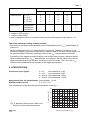
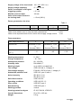
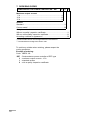
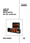
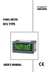
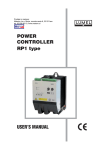
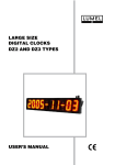
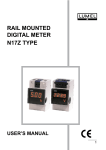
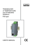
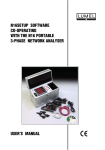
Prodaja in zastopa: Materm d.o.o. Morje, morska cesta 6, 2313 Fram tel: 02 608 90 10, www.materm.si POWER CONTROLLER RP7 TYPE USERS MANUAL POWER CONTROLLER RP7 TYPE USERS MANUAL CONTENTS 1. APPLICATION ....................................................................................................................... 5 2. BASIC REQUIREMEMNTS, OPERATIONAL SAFETY ....................................................... 5 3. POWER CONTROLLER SET ............................................................................................... 7 4. DESCRIPTION OF THE DESIGN and OPERATION .......................................................... 7 5. INSTALLATION and SETTING TO WORK ........................................................................... 9 6. SPECIFICATIONS ............................................................................................................... 10 7. ORDERING CODES ........................................................................................................... 12 8. MAINTENANCE AND GUARANTEE .................................................................................. 13 ! " 1. APPLICATION The RP7 power controller is destined to control the load power in function of the input control signal for following types of loads: l resistance loads, l resistance-inductance loads, and the control of induction motors and commutator motors at not high loads. The application area of RP7 power controllers includes: l electrical furnaces and drying constructions, particularly industrial tunnel and belt-type furnaces, furnaces for annealing and hard soldering, crucible furnaces and furnaces for hardening in salt bath, l devices of mechanical engineering, aggregates and extruding presses for plastics, devices for winding and tempering of springs, spot welding and seam welders, l production of glass and glazing, installations and devices for drying in infrared and ultraviolet radiation, ladles for glass melt and heating of feeding devices, l chemical and petroleum industries, facing heaters of tube installations, preheating installations 2. BASIC REQUIREMENTS, OPERATIONAL SAFETY Power controllers are applied in high-current installations in which devices under voltage can be a source of danger. Considering the personnel safety, one should observe following principles: l Devices can be installed, serviced and maintained exclusively by a suitably qualified personnel, having essential knowledge about equipment. RP7 power controllers should be connected to the power network according to the present operative regulations and standards concerning electrical installations, and concerning specially the protection against electric shocks. l During the start and operation of the starting system. One must comply with recommendations included in this users manual. Qualified personnel defines persons which are acquainted with the users manual, assembly starting and service of the product, and have appropriate qualifications to carry out these activities. Symbols located in this users manual mean: ? ! WARNING! Warning of potential, hazardous situations. Especially important. One must be familiar with this before connecting the power controller. The non-observance of notices marked by these symbols can occasion severe injuries of the personnel and the damage of the device. CAUTION! Designates a general useful note. If you observe it, handling of the power controller is made easier. One must take note of this, when the power controller is working inconsistently to the expectations. Possible consequences if disregarded! In the security scope the power controller meets the requirements of the EEC Low-Voltage Directive (EN 61010 -1 issued by CENELEC). # Remarks concerning the operator safety: 1. General l The RP7 power controller is destined to co-operate with other devices. l Non-authorized removal of the required housing, inappropriate use, incorrect installation or operation creates the risk of injury to personnel or damage to equipment. For more detailed information please study the users manual. l All operations concerning transport, installation, and commissioning as well as maintenance must be carried out by qualified, skilled personnel and national regulations for the prevention of accidents must be observed. l According to this basic safety information, qualified, skilled personnel are persons who are familiar with the installation, assembly, commissioning, and operation of the product and who have qualifications necessary for their occupation. 2. Transport, storage Please observe the notes on transport, storage and appropriate handling. Observe the climatic conditions given in Technical Data. 3. Installation l The power controller must be installed according to the regulation and instructions given in this users manual. l Ensure proper handling and avoid mechanical stress. l Do not bend any components and do not change any insulation distances. l Do not touch any electronic components and contacts. l Electronic Instruments may contain electrostatically sensitive components, which can easily be damaged by inappropriate handling. l Do not damage or destroy any electrical components since this might endanger your health! 4. Electrical connection l Before switching the power controller on, one must check the correctness of connection to the network. l In case of the protection terminal connection with a separate lead one must remember to connect it before the connection of the power controller to the mains. l When working on live instruments or devices, the applicable national regulations for the prevention of accidents must be observed. l The electrical installation must be carried out according to the appropriate regulations (cable cross-sections, fuses,). Additional information can be obtained from the users guide. l The documentation contains information about installation in compliance with EMC (shielding, grounding, filters and cables). These notes must be observed for all CE-marked products. l The manufacturer of the installation or installed devices is responsible for the compliance with the required limit values demanded by the EMC legislation. 5. Operation l Installations including RP7 power controllers must be equipped with protection devices according to the corresponding standard and regulations for prevention of accidents. $ l l After the power controller has been disconnected from the supply voltage, live components and power connections must not be touched immediately because capacitors can be charged. The housing must be closed during operation. 6. Maintenance and servicing l Please observe the manufacturers documentation. l Read all product-specific safety and application notes in this users manual. l Before taking the power controller housing out, one must turn the supply off. l The removal of the power controller housing during the guarantee contract period may cause its cancellation. 3. POWER CONTROLLER SET The set consists of: - RP7 power controller 1 pc. - users manual 1 pc. - guarantee card 1 pc. - fuse 1 pc When unpacking the power controller, please check the delivery completeness and whether the type and version code on the data plate correspond to the order. 4. DESCRIPTION OF THE DESIGN AND OPERATION The RP7 power controller is destined to be mounted on a wall or on a rail (E-06292, DIN EN 50 022-35) by means of a special catch. Power controller overall dimensions, spacing of assembly holes and the fixing way are presented on the fig. 1. 40,5 7 8 6 RP7 5 1 0...5 V 0...10 V 0...20 mA 4...20 mA 123 4 5 93 2 4 2 105 I lim a max 1 15 A U2 0V U/I Pot 3 13 105 50 Fig. 1. Overall and assembly dimensions 1 - protection cover, 2 - terminal strip, 3 - terminal of the protection wire 4 - fuse, 5 - DIP switch, 6 - radiator, 7 - catch, 8 - rail. % Servicing elements are disposed on the power controller frontal plate. - terminal strip, enabling the connection of load circuit wires, control wires or the potentiometer, - potentiometer Ilim, serving to the load current limitation, - potentiometer amax, serving to the triggering angle limitation, - lighting green diode (1), signalling the exceeding over 70% of the set power, - lighting red diode (2), signalling the fuse damage. The RP7 power controller has a bidirectional thyristor switch, which is a link controlled by the gate triggering system. It also includes a fuse destined to protect semiconductor elements, an RC two-terminal network and a varistor, protecting against commutation or connection overvoltages. The connection of the load is realised by the change of the load current connection angle in the function of the control analog signal or by means of the potentiometer. Runs of signals for this control are shown on the fig. 2. Input signal X X max t Voltage supplying the load circuit U Current in the load circuit Io t t Power delivered to the load Po P o max a t Fig. 2. Phase control, runs of occurring signals The RP7 power controller has functions ensuring a reliable and safe operation: ! l Limitation of the current load If the current value in the load circuit exceeds the threshold value set by the Ilim potentiometer, then the current limitation will operate independently on the control signal. The maximal value of the current flowing in the load circuit can be set in the range from 20% to 100% Io (for rated power load higher than 1/2 maximal power of the power controller). l Limitation of the triggering angle In case of power controller work with motors on can set the current Ir value necessary for the motor start by means of the amax potentiometer. The control range in this case is depended on the set current Ir value to the rated current In value. If the control signal value is lower than the value corresponding to the Ir value, then the triggering stoppage follows. & l Triggering delay of Soft-start type The soft-start type enables the change of the connection angle from p to 0 rad in the time ca 1.5 s, after the supply connection (switch W, fig. 3). l Detection and signalling of the load circuit current The 70% exceeding of the set current limitation value is signalled by the lighting of the green diode - 1 l Signalling of fuse damage In case of the fuse damage, the voltage on fuse terminals supplies the signalling system of the fuse damage (lighting of the red diode - 2). 5. INSTALLATION AND SETTING TO WORK After fixing the power controller according to the fig. 1, one must carry out connections of external circuits as shown on the fig. 3. U U1 U2 0V U/I Pot 1 2 3 4 5 6 0...20 mA 4...20 mA M ~ Load L1 N 0...5 V 0...10 V min max W Fig. 3. Marking and description of external terminals Cross-sections of supply wires: - to the load circuit (U1 and U2 terminals) - to the system of gate triggering (U terminal) ³ 1.5 mm2 ³ 0.35 mm2 - protective lead (terminal ³ 1.5 mm2 ) Maximal cross-section of supply wires: 2.5 mm2 Connect the L1, N supply to terminals 1 (U), 3 (U2). Connect the load between the terminal 2 (U1) and the phase L1 of the supply voltage. One must connect the input signal to terminals 4 (0 V), 5 (U/I). The manufacturer input signal is set on 0...10 V. The range of the input signal and the adaptation of the power controller to the load type can be chosen by the appropriate position of the DIP switch section, accessible after removing the power controller cover, fig. 1. The way of the switch setting is given in the table 1. ' Table 1 Switch sections 1 2 3 4 Control signal 0...5 V 0...10 V 0...20 mA 4...20 mA 0 0 1 1 1 0 1 1 0 0 0 1 0 0 0 1 Kind of load Resistance Resistanceinductance - - - - 5 0 1 0 - switch in OFF position 1 - switch in ON position In case of assignment from the potentiometer, set the control signal on the range 0...10. The power controller setting to work includes: - The setting of the load current limitation (set the handwheel of the amax potentiometer on maximum). Set the handwheel of the Ilim potentiometer on minimum. Observing indications of the instrument measuring the load current (at the maximal value of the input control signal), set the required value of the load current by means of the Ilim potentiometer handwheel. - The setting of the triggering angle limitation (use at the control of motor rotational speed). Set the handwheel of the amax potentiometer on maximum. Set the value of the control signal corresponding to the current Ir necessary to start the motor. Then, turn the amax potentiometer handwheel till the moment of the triggering stoppage. 6. SPECIFICATIONS Continuous input signal: 0...5 V input resistance: 3 kW 0...10 V input resistance: 6 kW 0...20 mA input resistance: 250 W 4...20 mA input resistance : 250 W Assignment from the potentiometer potentiometer : 10 kW Maximal output current 5 A, 10 A, 15 A The characteristic of the load capacity is presented on the fig. 4. Fig. 4. Maximal output current value in the function of the ambient temperature Output current [A] 20 15 10 5 RP73 RP72 RP71 0 20 30 40 50 60 o Ambient temperature [ C] 70 Supply voltage of the load circuit 195...230...253 V a.c Supply voltage frequency 47...50...53 Hz Power consumption of the gate triggering system £ 3.3 VA Minimal current output 100 mA Value of the output current in the locking state £ 15 mA (230 V) Power generated on the triac: Table 2 Maximal output current [A] 5 10 15 Power generated on the triac [W] 8 17 24 Value of the relative error to map the static characteristic Value of the expected short-circuit current of the supply voltage source ± 10% 2 kA Fuse parameters: Max. output current [A] Kind of fuse òi2 dt [A2 s] Table 3 5 Wickmann FF 6,3 A or Bussmann GBB-6 10 Wickmann FF 12,5 A or Bussmann GBB-12 < 15 15 Wickmann FF 16 A or Bussmann GBB-20 < 40 Working temperature 0...50°C Storage temperature - 25...70°C Atmosphere pressure 86...106 kPa Humidity class DIN 40040 F Working height up to 1000 m at rated load Test voltage VDE 0160 tab. 4, Category II Overvoltage category E-08109, VDE 0110 part.1, category II Admissible pollution level VDE 0110, part 2, level 2 Noise immunity IEC 801-2, 2 kV IEC 801-4, 8 kV Safe disconnection VDE 0160 5.6 Operating conditions VDE 0160 5.5.1.3 Place of use VDE 0875, part 3 Manufacturing VDE 0558, part 1 Working position vertical Housing protection degree IP 20, E-08106, VDE0470 Overall dimensions 50 x 105 x 105 mm Weight 0.5 kg < 120 7. ORDERING CODES SEMICONDUCTOR POWER CONTROLLER - RP7 X X X Maximum output current: 5 A ...................................................................................... 1 10 A ...................................................................................... 2 15 A ...................................................................................... 3 Version: Standard ..................................................................................... 1 Custom-made* ............................................................................ X Acceptance test: Without a quality inspection certificate .............................................. 1 With an extra quality inspection certificate ....................................... 2 According customers agreement** .................................................. X * Custom-made version must be agreed with the manufacturer. ** The manufacturer assigns the version code. To avoid any mistake when ordering, please respect the coding procedure: Example of ordering: Code: RP7 3 1 2 RP7 - Semiconductor power controller of RP7 type 3 - maximum output current = 15 A 1 - standard version 2 - with a quality inspection certificate. 8. MAINTENANCE AND GUARANTEE The RP7 power controller does not require any special periodical maintenance. In case of a fuse damage, the red diode (2) lights. To replace the fuse, one must: - disconnect the load circuit supply, - disconnect electrical connections from the terminal strip, - remove the power controller protection cover, - replace the fuse. NOTE: The radiator can be hot. Be careful. ! In case of some other incorrect operations: After the dispatch date and within the period stated in the guarantee card One should return the power controller to the Manufacturers Quality Inspection Dept. If the device has been used in compliance with the instructions, the Manufacturer guarantees to repair it free of charge. The disassembling of the housing causes the cancellation of the granted guarantee. After the guarantee period: One should send the device to repair it in an authorized service workshop. Spare parts are available for the period of five years from the date of purchase. Our policy is one of continuous improvement and we reserve the right to make changes in design and specifications of any products as engineering advances or necessity requires and revise the above specifications without notice. ! " # MEASUREMENT CONTROL RECORDING SALES PROGRAM n DIGITAL and BARGRAPH PANEL METERS n MEASURING TRANSDUCERS n ANALOG PANEL METERS (DIN INSTRUMENTS) n ANALOG and DIGITAL CLAMP-ON METERS n INDUSTRIAL and HOUSEHOLD CONTROLLERS n CHART AND PAPERLESS RECORDERS n POWER CONTROL UNITS and INVERTERS n AUTOMOTIVE DASHBOARD INDICATORS n ACCESSORIES FOR MEASURING INSTRUMENTS n MEASURING SYSTEMS (ENERGY, HEAT, CONTROL) n CUSTOM-MADE PRODUCTS WE ALSO OFFER OUR SERVICES IN THE PRODUCTION OF: n ALUMINIUM ALLOY PRESSURE CASTINGS n PRECISION ENGINEERING AND THERMOPLASTICS PARTS QUALITY PROCEDURES: According to ISO 9001 and ISO 14001 international requirements. All our instruments have CE mark. For more information, please write to or phone our Export Department April 2005 Lubuskie Zak³ady Aparatów Elektrycznych LUMEL S.A. ul. Sulechowska 1 65-022 Zielona Góra - Poland Tel. (48-68) 329 51 00 (exchange) Fax: (48-68) 329 51 01 e-mail: [email protected] http://www.lumel.com.pl Export Department: Tel: (48-68) 329 53 02 or 53 04 Fax.: (48-68) 325 40 91 e-mail: [email protected]