1
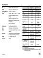
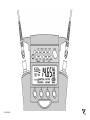
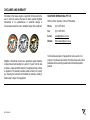
KI 7010B Series Automated Variable Optical Attenuator OPERATION & MAINTENANCE GUIDE DECLARATION OF CONFORMITY IN ACCORDANCE WITH ISO/IEC 17050:2004 Manufacturer’s Name: Manufacturer’s Address: Kingfisher International Pty. Ltd. 30 Rocco Drive, Scoresby, Victoria 3179, Australia hereby declares, that the products listed below Product Name: Model Number: Product Options: Automated Variable Optical Attenuator KI 7000 Series This declaration covers all options of the above product(s) comply with the essential requirements of the applicable European Directives: Low Voltage Directive 73/23/EEC and the EMC Directive 89/336/EEC, amended by 93/68/EEC, and carries the CE marking accordingly Directive 2002/95/EC on restriction of the use of certain hazardous substances in electrical and electronic equipment (RoHS) Directive 2002/96/EC on waste electrical and electronic equipment (WEEE) and conform to the following standards and specifications: MIL-PRF-28800F: 1996 Performance specification-Test equipment for use with electrical and electronic equipment, general specification IEC 60529: 2001/ EN 60529:1993+A1:2003 Degrees of protection provided by enclosures EMC Limit IEC 61326:2002 / EN 61326-1:1997+A1:1998+A2:2001+A3:2003 IEC CISPR 11: 2004/ EN 55011:1998+A1:1999 IEC CISPR 16-1:1999 IEC CISPR 16-2:1999 IEC 61000-3-2: 2005/EN 61000-3-2:2006 IEN 61000-3-3:2002/EN 61000-3-3:1995 IEC 61000-4-2:2001 / EN 61000-4-2:1995+A1:1998+A2:2001 IEC 61000-4-3:2002/ EN 61000-4-3:2002 IEC 61000-4-4:2004/EN 61000-4-4:2004 IEC 61000-4-5:2005/EN 61000-4-5:2006 IEC 61000-4-6:2004/EN 61000-4-6:1996+A1:2001 IEC 61000-4-11:2004/EN 61000-4-11:2004 Limits applicable to Group 1 Class B equipment Limits applicable to Class B equipment Limits applicable to Class B equipment 4kV CD, 8kV AD 3V/m, 80-1000MHz 1kV signal lines, 2kV power lines 1kV line-line, 2kV line-ground 3V, 0.15-80 MHz 0.5 cycle/100%/each polarity ICES-001: 2006 (Canada) CFR 47 FCC Part 15, Subpart B (Class B) (USA) FCC registration number: 90891 Supplemental Information: The product was tested in a typical configuration with Kingfisher International test systems. 2007-September -17 Date Bruce Robertson Name Technical Director Title For further information, please contact your local Kingfisher International sales office, agent or distributor. Revision: E Issue Date: 2007- September-17 OPERATION MANUAL KI7010B SERIES AUTOMATED VARIABLE OPTICAL ATTENUATOR Congratulations on your purchase of this instrument, which has been engineered to provide the best possible reliability, convenience and performance. To get the best use from your equipment and ensure its safe operation, please spend a few minutes to read this manual. Made in Australia. International Patents Granted © Copyright Kingfisher International Pty Ltd 5th Edition, September 2007 KI 7010B UM-5 1 CONTENTS Service and Support 4 Care of your Instrument 15 Introduction and Applications 5 Accuracy Considerations 16 General Safety Summary 6 Definition of Terms 17 Battery and External Power Operation 8 Specifications 18 Optical Connector 9 Ordering Information 19 Getting Started and Turning On 10 Maintenance 20 Simple Operation-Manual and Step Modes 11 Performance Verification Test 21 Absolute/Relative Display Mode 12 Quick Reference Guide 28 Program Mode 13 Disclaimer & Warranty 30 PC Interface and External Software 14 User Notes 31 Appendix - Remote Control Commands 34 PLEASE REFER TO THE CONTROL PANEL PICTURE IN THE QUICK REFERENCE GUIDE SECTION OF THIS MANUAL KI 7010B UM-5 2 KI7010B SERIES AUTOMATED VARIABLE OPTICAL ATTENUATOR KI 7010B UM-5 3 SERVICE AND SUPPORT Applications Support Please visit www.kingfisher.com.au to see our comprehensive Application Notes written to support instrument users. Look at www.kingfisher.com.au to find distributor details from the Contact Us section. Our local agents are able to offer excellent applications advice in your language and time zone. Please visit our website on www.kingfisher.com.au for a current list of regional service centres. If returning equipment to Kingfisher International for service or calibration, please download and complete the Return Material Authorization Form located on the Support page on our web site. To avoid delays and minimise disruption for our customers, Kingfisher International offers a fixed price repair service. For the staff at our fully equipped service and calibration centre, it is their pleasure to keep your equipment performing at its very best. Otherwise if you are having difficulties, please feel free to contact [email protected] for applications support. Instrument Service Qualified personnel must perform adjustment, maintenance or repair of this product. To obtain service, please contact your local Kingfisher International distributor or our office in Australia: Tel: (61) 3-9757-4100 Fax: (61) 3-9757-4193 Email: [email protected] KI 7010B-UM-5 4 INTRODUCTION AND APPLICATIONS The KI7010B Series Automated Variable Optical Attenuator provides optimum performance for testing fiber optic transmission systems, sub systems and components by creating accurate variable optical losses. Compact and simple to operate, this is the ideal equipment for field or laboratory use by installers, technicians and engineers. Typical applications: • Measurements, where traceability and full documentation is required • Transmission equipment commissioning • Precision linearity testing of sub systems and components • Automated production and laboratory testing • Quality assurance and acceptance testing The single mode version is calibrated at 1310 / 1490 / 1550 nm or 1310 / 1550 / 1625 nm over the range of 2 ~ 60.00 dB, and the multimode version at 850 & 1300 nm over the range of 3.00 ~ 60.00 dB. The instrument features exceptional wavelength flatness, excellent PDL, ORL and PMD performance, making it ideal for use in CWDM /DWDM systems. Accuracy and linearity are obtained during manufacturing by calibrating every incremental 0.05 dB setting of the attenuator at KI 7010B-UM-5 each wavelength. Attenuation achieved by movement of a neutral density filter positioned in the optical path; it remains unchanged when the instrument is turned off. Optimal design of the optical path enables low back reflection. A convenient menu-driven interface guides the user through operational sequences with hidden keypad access of advanced functions. Instrument features various display modes, including actual, relative and arbitrary attenuation. Available operational modes include simple manual, step, multiple user settable program modes and remote control via PC. Software for external control can be downloaded from our website. The design of the instrument includes shock absorbing corners for drop protection and tough polycarbonate housing. The latest materials and methods have been used to produce an elegant, yet rugged instrument. The interchangeable optical connectors are protected by a snap on cover and are easily disassembled for cleaning. A wide variety of connector styles are available as an option. The battery life varies from 200 to 600 hours, depending on motor activity. Alternatively, instrument can be used with optional external power supply OPT103B. 5 GENERAL SAFETY SUMMARY The following safety signs and symbols specify general safety precautions which must be observed during all phases of operation, service and repair of this instrument. Failure to comply with these precautions or with specific warnings elsewhere in this manual violates safety standards of design, manufacture and intended use of the instrument. Kingfisher International assumes no liability for the customer’s failure to comply with these requirements. Before operation, review the instrument and user manual for safety instructions. You must follow these to ensure safe operation and to maintain the instrument in safe condition. WARNING! The WARNING! sign denotes a hazard. It calls attention to a procedure, practice or the like, which, if not correctly performed or adhered to, could result in injury. Do not proceed beyond a WARNING! sign until the indicated safety conditions are fully understood and met. CAUTION! The CAUTION! sign denotes a hazard. It calls attention to an operating procedure, or the like, which, if not correctly performed or adhered to, could result in damage to or destruction of part, or all, of the product. Do not proceed beyond a CAUTION! sign until the indicated conditions are fully understood and met. KI 7010B-UM-5 Safety Symbols ! The apparatus will be marked with this symbol when it is necessary for the user to refer to the instruction manual in order to protect the apparatus against damage. Initial Inspection Inspect the shipping container for damage. If there is damage to the container or cushioning, keep them until you have checked the contents of the shipment for completeness and verified the instrument both mechanically and electrically. If the contents are incomplete, mechanical damage or defect is apparent, or if an instrument does not pass the operator’s checks, notify the nearest Sales/Service Office. Do not perform electrical tests when there are signs of shipping damage to any portion of the outer enclosure (covers, panels, and so on). To check instrument performance, please refer to Performance Verification Tests section of this manual. WARNING! You must return instruments with malfunctions to a Service Centre for repair and calibration. 6 GENERAL SAFETY SUMMARY Operating Environment Safety The KI7010B Automated Variable Optical Attenuator can be operated at temperatures between -15 °C and +55 °C and at relative humidity of less than 95 %. This instrument contains no hazardous optical or electrical items. When using this equipment, optical safety precautions should be observed. Storage & Shipment Line Power Requirements The KI7010B Automated Variable Optical Attenuator can be stored and shipped at temperatures between - 25 °C and + 70 °C and at relative humidity of less than 95 %. Protect the unit from temperature extremes that may cause condensation within it. The KI7010B Automated Variable Optical Attenuator operates at line power, when applied to the optional external power supply OPT103B. KI 7010B-UM-5 7 BATTERY AND EXTERNAL POWER OPERATION Battery Operation: The instrument is powered by two 1.5V alkaline ‘C’ size batteries equivalent to 300 hours continuous operation. About 30 % capacity is obtained when using two 1.5V alkaline ‘AA’ batteries and supplied adaptors, or 50 % capacity when using two 1.2V rechargeable NiMH ‘C’ size batteries. When the batteries are low, this will be indicated on the display with a battery symbol. At this stage, there is approximately enough energy for another 30 minutes of use. CAUTION! Do not use lithium batteries or other batteries with a nominal voltage greater than 1.8 V. The instrument will be damaged. Protect our environment! Some batteries contain toxic heavy metals, so please return them to a recycling centre for appropriate disposal. External Power Operation: The instrument can be powered by an external 9V DC input, using a universal power pack OPT103B. To save energy, the instrument automatically turns off after 10 minutes without operation. To change the batteries, open the cover of the battery compartment at the base of the instrument, remove the batteries and insert new ones. KI 7010B-UM-5 8 OPTICAL CONNECTOR To access the optical connectors, grasp the top corners of the instrument, and pull off the covers. CAUTION! Use of bare fiber adaptors is not recommended, or permanent connector damage will occur. The optical port is mounted on a swivel, which allows the connector to be angled outwards for accessibility, and then pushed back and covered with the snap cover to provide dirt and drop protection. How to clean the optical connectors: The attenuator is either PC or APC connector specific. This is determined when ordering the instrument. Different styles of standard and optional connector adaptors can be easily fitted by the user. Please see the following page for instructions on connector adaptor installation and removal. The supplied standard connector adaptors have ceramic sleeves and do not cause metal dust contamination. CAUTION! Do not use damaged or incompatible connectors. When not in use, keep the test ports and connectors covered. To minimize connectors wear, instrument can be stored without removing the test leads. Never touch connector tips with your fingers, since body oils and dirt can impair connector performance. KI 7010B-UM-5 WARNING! Disable source when cleaning optical interface. Remove batteries before using a microscope to inspect instrument connectors. Always clean the mating connector tip and ferrule before mating, using approved materials. CAUTION! Never use abrasive cleaners, or permanent connectors damage may occur. To clean the interface without removing the adaptor, use ‘ stick ‘ style connector cleaner . This cleans both the adaptor and end face in one operation. Alternatively, first remove the interchangeable adaptor to access the glass interface. Then blow away any dust or dirt with compressed air. If this is not sufficient, then clean the interface by rubbing a microfiber lint-free lens cleaning cloth over the surface using small circular movements. 9 GETTING STARTED AND TURNING ON Pull off instrument connector covers. To install a connector adaptor, align the locating slot on the side of the through adaptor with that on the instrument connector, and press it on. To remove an adaptor, press the release button on the back of the instrument and then pull off the adaptor. It is easier to pull off the adaptor with a test lead in place, since this gives better grip. On older models without the release buttons, move the connector port to its mid-way point, then pull off the adaptor. Install the batteries, or plug in external power into the socket at the top of the instrument. To switch on the instrument for permanent operation, press and hold down [Power] for 3 seconds until ‘PERM’ is displayed. Display will briefly show all segments and then firmware version. Pressing [Power] again will turn the instrument off. KI 7010B-UM-5 Should the instrument fail to turn on, it is possible that the microprocessor needs re-booting. To do this, remove the batteries or external power for at least 20 seconds, then re-insert to re-boot the software. The current attenuation and various user settings remain unchanged when the attenuator is switched off. To backlight the display temporarily, press light button ☼ (first button on the left, top row). To illuminate continuously, press and hold down light button for 3 seconds. Note that the hidden keypad is accessed by pulling up the hinged display cover. To add the carry strap, slip the end of the strap through the slit on the curved section at the back of the instrument, and secure the buckle. 10 SIMPLE OPERATION-MANUAL AND STEP MODES To achieve the simple level of operation, connect Light source and Power meter with a patch lead and turn both instruments on. After the stabilisation period, set a reference (so that the meter reads 0.00 dB) and then connect the Attenuator between the source and meter. Turn on the Attenuator. For correct display of attenuation, the calibration wavelength on Attenuator should be set to the appropriate window (eg 850,1300nm for multimode or 1310, 1490, 1550, 1625 nm for single mode) corresponding to Light source operating wavelength. The calibration wavelength is displayed on the top left of the LCD. To select calibration wavelength, press [], then [-/+] button. Press [SET] to set the required wavelength. If the wavelength is selected incorrectly, the displayed attenuation will be inaccurate. Once the wavelength has been fixed, the attenuation level can be also set as required with the [-/+] button. To return to wavelength selection, press [MENU]. connector uncertainty. Note that any source drift will also cause extra reading variations. The attenuator reading displays the complete instrument loss, including the average optical connector loss. The user can define attenuation step size in increments of 0.05 dB from 0.05 dB to 10 dB. This is very useful feature, when performing linearity tests or simply to speed up operation, if the default step size of 0.1 dB is not convenient. For example, when testing optical power meter linearity, the step size might be set to 10 dB. To operate in the step mode, simply press [POWER] [] [-/+] [SET] and then [STEP] button. Pressing the [-/+] button will now increment attenuation according to the previously used step size. To view the current step size, press [SET STEP] button. The instrument sets the requested attenuation level with an internal motor drive. While the motor is in operation, a ‘BUSY’ indicator will show on the LCD. To change the step size, press the [SET STEP] button, then use [-/+] button to display the required step size, and press [SET] to store. The unit will now operate in step mode, using the new step value. The attenuation can be set outside the calibrated range, in which case ‘HI’ or ‘LO’ will be displayed. Note that some instrument functions are locked out when ‘HI’ or ‘LO’ are displayed. To exit this mode, press [MENU]. If the operating wavelengths of the source, meter and calibration wavelength of attenuator are correctly set, the meter and attenuator should display similar readings, with discrepancies caused mainly by KI 7010B-UM-5 11 ABSOLUTE / RELATIVE DISPLAY MODE Absolute/Relative display mode is a useful feature to allow user switching between these two modes depending on which value is required. Absolute attenuation value is displayed in dB. In relative mode, ‘REL dB’ shows on the top right side of the display. Sometimes it is convenient to display attenuation relative to a reference value, eg: • The display is zeroed at a particular point, and subsequent readings are relative to this. • The display is set to an arbitrary value. For example, it can be set to display the absolute optical power coming out of the attenuator when a particular light source is attached or to read total link loss including the attenuator loss. Note that negative attenuation values can also be displayed in this mode. KI 7010B-UM-5 To enter Absolute/Relative display mode, set the attenuation level as required and press [ABS/REL]. To zero the display, press the [REL] button. Press [SET STEP] to adjust attenuation step, then [-/+] button to increase or decrease attenuation. To set the display to an arbitrary value, adjust the attenuation with the [-/+] button, then press [SET]. Press [SET STEP] to adjust attenuation step, then [-/+] button to increase or decrease attenuation. To exit this mode, press the [ABS/REL] button again or [MENU]. 12 PROGRAM MODE Program mode is a powerful productivity enhancing facility, as it enables operator to use pre-set routines. The program mode is particularly useful when performing optical margin testing, since a slow uniform increase of attenuation can be automatically achieved over a desired range. 15 different user programs (1 to 9 and A to F) can be set up and stored in non volatile memory. To use a previously set up program: To set a parameter, press a parameter button on hidden control panel, then the [-/+] button to select the desired value. The selected value will be displayed. To abort the changes, press [CANCEL MEMORY]. You can use the hidden control panel to set up the following parameters: Parameter button Parameter - Turn the instrument on and press [PROGRAM]. [] calibration wavelength - Select the desired program with the [-/+] button, press [SET] and then [GO]. [START] start position [FINISH] stop position - Press [STOP] to halt the program, then press [GO] if you wish to continue. [STEP] attenuation step - Press [RESTART] to restart the program. [PERIOD] attenuation step period To exit program mode press [STOP], then [MENU]. Setting up Programs: Select the desired program location:[PROGRAM] [-/+] [SET]. To set up programs, access the hidden control panel by lifting up the hinged LCD cover. KI 7010B-UM-5 When the required parameters have been adjusted, press [SET MEMORY] to save changes. NOTE: Programs 1, 5, 6, 7 were pre-loaded in the factory. These can be changed by the user. 13 RS232 INTERFACE AND EXTERNAL SOFTWARE The KI7010B can be remotely accessed and controlled from an external PC via RS232 interface. When instrument is controlled from PC, RS232 symbol will be displayed and auto power-off will be defeated. The connection details of the instrument and connecting cables are as follows: Some (out of spec) serial ports need a 10K resistor in the D connector across wires 1 & 2. Kingfisher Attenuator Remote Control software Remote control software available from our website at www.kingfisher.com.au/products/ki7010/7010Software is used to provide external control of the Kingfisher KI7010B Automated Variable Optical Attenuator. As installed, it provides many useful functions. Since it is written in C using Labwindows, it is also easy for a programmer to modify. Wire 1(Screen) Wire 2 Wire 3 Remote sequencing and control from a PC Instrument Jack Plug Body (Gnd) Ring (Tx) Tip (Rx) Ideal for automation of measurement sequences 9 Pin D connector for RS232 Pin 5 (Gnd) Supports three sequences with varying times/increments Pin 2 (Rx) Pin 3 (Tx) Baud Rate The baud rate can be set to: 0.3, 0.6, 1.2, 2.4, 4.8, 9.6, 19.2, 38.4 and 56.0 Kb/sec. The default baud rate is 9.6 Kb/sec. To set the baud rate, on the hidden keypad, press [BAUD RATE], then [-/+] to set the rate, followed by [SET MEMORY]. At turn on, the default is restored. Local/Remote modes The hidden keypad enables the user to lock out the front panel controls by pressing [LOCAL] or [REMOTE]. KI 7010B-UM-5 Auto-discovery of attached instrument Progress indicator System Requirements: Windows 9X or higher (tested on WinXP) with RS232 port. An RS232 - USB adaptor is available. 14 CARE OF YOUR INSTRUMENT • Follow the instructions in this manual on optical connector care. • • During prolonged storage, remove batteries to eliminate the possibility of acid leakage. Use only high quality sealed alkaline or NiMH batteries. During storage and transport, keep the instrument in its carry case to protect against crushing, vibration, dust and moisture. KI 7010B-UM-5 • The instrument is resistant to normal dust and moisture, however it is not waterproof. If moisture does get into the instrument, dry it out carefully before using it again. Where possible, keep instrument away from direct sunlight. • Clean the instrument case using soft damp cloth. Do not use alcohol or any solvents, otherwise paint will be damaged. • The instrument housing is made of tough polycarbonate material with impact absorbing rubberised corner features, and is therefore drop resistant. 15 ACCURACY CONSIDERATIONS All Measurements • Optical connectors should be kept clean and in good condition. • There are limits on the repeatability of the attenuator setting. This is typically ± 0.03 dB. • There may be inaccuracies due to the operational wavelength being slightly different to the calibration wavelength. This error is normally small, since the instrument has a flat spectral response. The expected inaccuracy can be approximated as: Actual attenuation = display reading - 0.0002 x n x display reading, where n = wavelength discrepancy in nm For example, with the attenuator set at 1310 and 60 dB, and with 1550 nm light, the actual attenuation will be approximately 57.12 dB. • Polarisation changes create disturbances in both the optical system and measurement equipment. To reduce this, keep your system physically stable. Keep patch leads neat, coiled and stable. • Temperature effects are too small to characterise reliably, and are unlikely to be an issue. • All Ge power meters are inherently non-linear by about 0.04 dB. Ge meters also have temperature dependent calibration drift at 1300 nm of typically 0.03dB per 10 ºC. This will KI 7010B-UM-5 noticeably degrade the accuracy of work done with such a meter. • Light source power may drift: when you have finished a test, go back to the start position to check if your meter reading is still within acceptable limits. • Cladding mode light transmission can affect some fibre types (most fibres strip off cladding modes). • Measurements on multimode fibre may be unrepeatable and inaccurate unless a mode filter is used to obtain an equilibrium modal distribution. You may find that your power meter linearity disagrees with the attenuator at low power levels. Many power meters have poor linearity at low power levels. If in any doubt, introduce a step attenuator into the system (for example 20 dB, a bad connection will suffice!), and repeat similar power meter readings using a different region of the attenuator. For example, if during testing the power meter disagrees with the attenuator where the meter reads below -40 dBm and the attenuator was between -35 and -50 dB to achieve these readings, try introducing an additional 20 dB loss somewhere else. Now repeat the measurement with the power meter still reading below -40 dBm, but to achieve this, the attenuator is reading between -15 and -30 dB. If the same non-linearity is evident, then it is the power meter that is non linear. 16 DEFINITIONS OF TERMS Power capability: the input power not to be exceeded to avoid destroying the instrument. Wavelength dependence: variations in set attenuation due to instrument spectral response. Linearity/Repeatability: limits on the repeatability of the attenuator setting. Attenuation - Low wavelength dependence ATTENUATION, dB 20 15 10 5 0 1310 1330 1350 1370 1390 1410 1430 1450 1470 1490 1510 1530 1550 1570 1590 1610 WAVELENGTH, nm KI 7010B-UM-5 17 SPECIFICATIONS Size: Weight: Operating / Storage: Power: Display: 190 x 130 x 70 mm, 7.9” x 5.4 x 2.9 700 gm, 1.5 lb. Shipping 2 Kg, 4.4 lb -10 to 55 °C / -25 to 70 °C 2 alkaline / NiMH ‘C’ cells or 2x ‘AA’ cells with AA-to-C size battery converter (7.6 A/hr) External 9V DC with 2.5 mm +ve pin. Selectable auto-off, low battery indicator, back lit display. Battery life 200-600 hrs For setting advanced functions. Polycarbonate, 1 meter drop tested. 3.5 mm jack connector, default baud rate 9.6Kb/sec Performed without opening the instrument. Recommended calibration cycle: 3 years 4 ½ digit high contrast LCD Resolution: 0.05 dB Hidden keypad: Case: RS232: Calibration: Singlemode Multimode Fiber Type 9.5 / 125 m 50 or 62.5 m Range 2 ~ 60.00 dB 3.00 ~ 60.00 dB Resolution 0.05 dB 0.05 dB Linearity / Repeatability 0.03 dB 0.10 dB Absolute Uncertainty¹,² 0.30 dB 0.30 dB + 30 dBm + 30 dBm 60 dB 60 dB < 0.1 dB < 0.1 dB < 1 ps n/a 1200 to 1650 nm 700 to 1400 nm Power Capability Optical Return Loss (ORL)³ Polarisation Dependent Loss (PDL) Polarisation Mode Dispersion (PMD) Operating range Calibration dependence dependence DWDM S/C/L band over Thermal stability temperature. over 1310 / 1490 / 1550 1310/1550/ 1625 1300-1625 nm: < ±0.25 dB up to 15 dB < ±0.5 dB up to 20 dB 1490-1610 nm: < ±0.2 dB up to 15 dB < ±0.3 dB up to 20 dB ± 0.02 dB 850 /1300 nm 850-1300 nm: < ±0.5 dB up to 20 dB ± 0.02 dB Note 1: At calibration wavelength Note 2: Accuracy achieved in use will depend on connector performance Note 3: Using APC connectors, or limited by connector performance, which is typically 45 dB for singlemode PC or 28 dB for multimode PC connectors KI 7010B-UM-5 18 ORDERING INFORMATION Ordering Information: Optional Interchangeable Connector Adaptors: Automated Variable Optical Attenuator 1310 / 1490 / 1550 / 1625 nm singlemode, PC 1310 / 1490 / 1550 / 1625 nm singlemode, APC 1310 / 1550 / 1625 nm singlemode, PC 1310 / 1550 / 1625 nm singlemode, APC 850 / 1300 nm multimode, 50 m 850 / 1300 nm Multimode, 62.5 m KI 7013B KI 7013B-APC KI 7012B KI 7012B-APC KI 7020B KI 7021B Standard Accessories: ST, SC, FC connector adaptors, PC software and RS232 cable, User Manual, Quick Reference Guide, C cell batteries, AA-to-C size battery converter, NATA (ILAC) traceable calibration certificate, carry strap, soft carry pouch & protective holster. Optical Connectors: KI7010B Automated Variable Optical Attenuator has interchangeable optical connectors. The ferrule type is fixed and customer specified as either PC or APC. Green is associated with APC connectors. This instrument is supplied with metal free interchangeable connector adaptors to avoid critical contamination of connectors used in high power applications Please order any number of additional connector adaptors. KI 7010B-UM-5 Description P/N Description P/N D4 OPT055 LC / F3000 OPT072 E2000/LSH OPT060 MU OPT080 E2000/LSH, green OPT060G SMA905/906 OPT082 LSA/DIN 47256 OPT071 Optional Accessories: Description P/N Power Pack, 90~240V IEC OPT103B Carry case for two instruments OPT153 Large carry case OPT154 USB-RS232 converter OPT188 Please enquire for warranty extension options and non-standard specifications or visit our web site for other fibre optic test instruments. 19 MAINTENANCE This instrument contains static sensitive devices. Anti-static handling procedures should be observed at all times when handling internal circuits. Please note there are no user adjustable internal components, fuses, or calibration features. If using a soldering iron, be certain never to touch it onto the optical fibers, since damage to the plastic coating will cause subsequent fiber breakage. Maintenance CAUTION! Do not open unless the warranty has expired, and you are authorised to do so. Opening the unit will invalidate any warranty claim. The optical attenuator module is sealed and not accessible. A problem with the optical module will require return to Kingfisher International for repair. The linear servo motor is geared through a sealed high reduction gearbox. Position feedback is taken from the attenuator vane. The entire servo system has been designed to be very robust and with plenty of spare torque to overcome sticky oil and other start up problems. Remaining problem that the user might be able to service is mechanical parts coming loose. Opening the Instrument: • • • • Use static protected procedures. Remove the batteries, and leave the battery cover open. Pull open the optical connector covers. Place the instrument face down on a soft mat, and undo the 6 screws in the rear housing. • The instrument can now be gently pulled apart. • The instrument will come into two halves joined by a ribbon cable. The optical section is located in the bottom half, with the microprocessor, supply, calibration constants and controls in the top half. • Hinged display cover removal can be done at this point. • The ribbon cable can be disengaged to completely separate the instrument halves. • Further disassembly from this stage should be easily apparent to a technician. General electrical parameters are as follows: Vss to Vcc = 3.3 V, Battery power down current about 0.3 mA, active current about 11 mA, motor current is very difficult to measure, but is typically about 150 mA. • • KI 7010B-UM-5 Do not attempt to dismantle the optical module, as it contains extremely precisely aligned optical components. Re-assembly is the reverse of the above procedure. 20 PERFORMANCE VERIFICATION TEST All tests can be performed without opening the instrument. The test procedures described in this section are for performance verification of a KI7011B Automated Variable Optical Attenuator. Due to large number of possible instrument configurations, it is not possible to give detailed test procedures for all options in this manual, so some parameters may need adjusting to the appropriate specifications. Required Equipment: this is the required equipment for the performance test listed. Any equipment that satisfies the critical specifications of the instruments given in the table may be substituted for the recommended models. Test Record: results of the performance test may be tabulated on a photocopy of the Test Record provided at the end of the test procedure. It is recommended that you fill out the Test Record and refer to it while doing the test. Any changes in the specifications due to manufacturing changes, design or traceability to NATA will be covered in a user manual change supplement or revised manual. Such specifications supersede any that were previously published. General Instructions Perform each step in the order given, using the corresponding test equipment. Use Tables 1 ~ 3 to record test details. The SMF/MMF test lead fiber type and PC/APC connector polish must be matched to the instrument type. Ensure that all optical connections are dry and clean. DO NOT USE INDEX MATCHING OIL. For cleaning, please refer to the cleaning instructions given in the section ‘Optical Connector’. Check that all patch leads are fixed to the table to avoid movements during measurements. Test Failure: if the instrument fails any performance test, return it to the nearest Sales/Service office for repair. Make sure that the ambient conditions are in the following ranges: Temperature: 21 ± 3 ºC Instrument Specification: specifications are the performance characteristics of the instrument that are certified, and are the limits against which the equipment under test can be tested. Relative humidity: 45 to 75 % KI 7010B UM-5 21 PERFORMANCE VERIFICATION TEST Attenuator Linearity / Accuracy Test 1. Connect the equipment as shown in Figure 1: Power Meter Light Source Figure 1. Test set up for KI 7010B Series Attenuator Linearity/Accuracy Test 5. Connect the Light source and Power meter to the Attenuator as shown in Figure 2. Set the Attenuator to 1310 nm. Power Meter Attenuator Light Source Figure 2. Test set up for KI7010B Series Attenuator Linearity/Accuracy Test 2. Switch on the instruments. 6. Set the Attenuator to 2, 5, 10, 20, 30, 40, 50, 60dB (settings1~ 8). Note the displayed power levels in the test record, Table 4. 3. On Light source, enable the source. Set Light source and Power meter to 1310 nm. 7. Repeat the Attenuator Linearity /Accuracy Test at 1490nm and 1550 nm. 4. Zero the meter by pressing [Abs/Rel] and then holding [Set Ref] for 3 seconds. KI 7010B UM-5 22 PERFORMANCE VERIFICATION TEST Alternative Method for Linearity / Accuracy Test, using Loss Test Set 5. Set the Attenuator to 2, 5, 10, 20, 30, 40, 50, 60dB (settings1~8). Note the displayed power levels in the test record, Table 4. 1. Switch on Loss Test Set. 6. Repeat the Attenuator Linearity /Accuracy Test at 1490nm and 1550 nm. 2. Connect Light source to Power meter, then enable the source. Set the source to 1310 nm 3. Zero the meter by pressing [Abs/Rel] and then holding [Set Ref] for 3 seconds. 4. Connect the Attenuator and Loss Test Set as shown in Figure 3. Set the Attenuator to 1310 nm. Attenuator . Loss Test Set Figure 3. Test set up for KI7010B Series Attenuator Linearity/Accuracy Test (alternative method) KI 7010B UM-5 23 PERFORMANCE VERIFICATION TEST Instrument / Accessories Recommended Model Required Characteristics Alternative Model Optical Light Source KI7402 KI734X, KI7800, KI7300 Optical Power Meter KI7600 KI734X, KI6000, KI7700, KI7600 Optical Attenuator KI7011B KI7010A SMF patch leads Connector adaptors Table 1. Required Equipment for KI7010B Series Performance Verification Test. KI 7010B UM-5 24 PERFORMANCE VERIFICATION TEST Model: Date: Serial No.: Ambient Temperature: C Options: Relative Humidity: % Firmware Revision: Line Frequency: Hz Test Facility: Customer: Performed by: Report No.: Special Notes: Table 2.General Test Record for KI7010B Series KI 7010B UM-5 25 PERFORMANCE VERIFICATION TEST Description 1. Optical Light Source 2. Optical Power Meter 3. Optical Attenuator Model No. Trace No. Calibration due date 4. 5. 6. 7. 8. 9. 10. Accessories SMF patch leads Connector adaptors Table 3. Equipment Record for KI7010B Series Performance Verification Test. KI 7010B UM-5 26 PERFORMANCE VERIFICATION TEST Model: Report No.:______________ Date:________________ Linearity / Accuracy Test Wavelength = Setting Attenuator Setting, dB Minimum Specification, dBm (-0.3dB of Reference.) Power Meter Measurement results, dBm Maximum Specification, dBm (+0.3dB of Reference.) 1. 2.00 -2.30 -1.70 2. 5.00 -5.30 -4.70 3. 10.00 -10.30 -9.70 4. 20.00 -20.30 -19.70 5. 30.00 -30.30 -29.70 6. 40.00 -40.30 -39.70 7. 50.00 -50.30 -49.70 8. 60.00 -60.30 -59.70 Measurement Uncertainty: ___________dB Table 4. Linearity/Accuracy Test Record for KI7010B Series KI 7010B UM-5 27 QUICK REFERENCE GUIDE - KI7010B SERIES AUTOMATED VARIABLE OPTICAL ATTENUATOR To install a connector adaptor, align the locating slot on the side of the adaptor with that on the instrument connector, and press it on. To remove an adaptor, press the release button on the back of the instrument and then pull off the adaptor. It may be easier with a test lead in place. To turn on the instrument for permanent operation, press [POWER] for 3 seconds until ‘Perm’ is displayed at the top of the LCD. To select calibration wavelength, press [] [-/+] [SET]. To set attenuation level, press [-/+]. Low battery is indicated with a battery symbol. ABSOLUTE / RELATIVE DISPLAY MODE To enter Absolute/Relative display mode, set the attenuation level as required and press [ABS/REL]. To zero the display, press [REL]. To set the display to an arbitrary value, adjust the attenuation with the [-/+] button, then press [SET]. To exit this mode, press [ABS/REL] or [MENU]. PROGRAM MODE To use a previously set up program, press [PROGRAM] [-/+] [SET] and [GO]. To halt the program, press [STOP]. Press [GO] to continue. Press [RESTART] to restart the program To exit this mode, press [STOP] then [MENU]. STEP MODE To operate in the step mode, simply press the [STEP] button. Pressing the [-/+] button will now increment attenuation according to the previously set step size. To view the current step size, press [SET STEP]. To adjust the step size, press [SET STEP] [-/+] [SET]. The unit will now operate in step mode using the new step value. KI 7010B UM-5 28 KI 7010B UM-5 29 DISCLAIMER AND WARRANTY Information in this manual is given in good faith for the benefit of the user. It cannot be used as the basis for claims against Kingfisher International or its representatives, if accidental damage or inconvenience results from use or attempted repair of the equipment. Kingfisher International products are guaranteed against defective components and workmanship for a period of 3 years from the date of delivery, unless specifically stated in the original purchase contract or agreement. This warranty excludes optical connectors or incorrect use. Opening the instrument will invalidate the warranty. Liability is limited solely to repair of the equipment. KI 7010B UM-5 KINGFISHER INTERNATIONAL PTY LTD 30 Rocco Drive, Scoresby, Victoria 3179 Australia Phone: (61) 3-9757-4100 Fax: (61) 3-9757-4193 E-mail: [email protected] Website: http://www.kingfisher.com.au Technical data is subject to change without notice as part of our program of continuous improvement. Therefore please verify critical parameters before ordering. Australian and international patents granted. 30 NOTES KI 7010B UM-5 31 NOTES KI 7010B UM-5 32 NOTES KI 7010B UM-5 33 APPENDIX – REMOTE CONTROL COMMANDS There are around 50 commands for communicating between a controller ( computer ) and the attenuator. The commands sent to the attenuator are transferred as a block of bytes in binary form with an inverted checksum byte, and on completion of the command, the attenuator responds with the checksum byte with the following structure: Command byte | Data byte 1 | Data byte 2 | Checksum byte Checksum byte = the complement of (Command byte + Data byte 1 + data byte 2) The return commands sent by the attenuator to controller are transferred as a block of bytes in binary form with an inverted checksum byte as follows: Data Byte 0 | Data Byte 1 | Data Byte 2 | Checksum Byte Checksum byte = the complement of (Data byte 0 + Data byte 1 + data byte 2) The approximate equivalent key press or user activity is shown in (brackets). KI 7010B UM-5 34 APPENDIX – REMOTE CONTROL COMMANDS The command data format is: Wavelength, Program Wavelength 1 ( bytes ) 0 = wavelength 1, 1 = wavelength 2, 2 = wavelength 3, 3 = wavelength 4 Attenuation, REL attenuation, REL value, Program start Value, Program Finish Value: 2 value = 37.75 dB. 37.75/0.05=755 decimal, so high byte = 02 hex, low byte = F3 hex Step Size, Program step size 1 step = 3 dB, 3.00/0/05 = 60 decimal, step = 3C hex ABSREL_flag 1 0 = absolute, 1 = relative RELisMinus 1 REL attenuation is: -ve if 1, +ve if 0 Program No 1 Prog 3 = 3 decimal Program Step Period 1 Step period = 2 sec, program period = 1 Commands sent by the controller to the attenuator: Local / remote instrument commands to enable / disable instrument controls: Description Bytes Note Start remote mode ( remote ) 70h / 43h / 5bh / checksum Disables keypad Description Bytes Note End remote mode ( local ) 9bh / 43h / 5bh / checksum Enables keypad KI 7010B UM-5 35 APPENDIX – REMOTE CONTROL COMMANDS Manual mode operation commands: Description Bytes Note Read wavelength in manual mode ( read wavelength display ) 87h / 43h / 5bh / checksum Sends’ Return wavelength ‘ block. Description Bytes Note Select wavelength in manual mode ( + - ) 88h / wavelength / 5bh / checksum Use before command: Set wavelength in manual mode Description Bytes Note Set wavelength in manual mode ( set ) 89h / 43h / 5bh / checksum Use after command: Select wavelength in manual mode Set attenuation commands: Description Bytes Note Read current attenuation ( read attenuation display ) 8ah / 43h / 5bh / checksum sends ‘ Return current attenuation ‘ block. Description Bytes Set attenuation ( + - ) 8bh / attenuation high byte / attenuation low byte / checksum Set attenuation in Step mode commands: Description Bytes KI 7010B UM-5 Set attenuation in step mode ( + - ) 93h / attenuation high byte / attenuation low byte / checksum 36 APPENDIX – REMOTE CONTROL COMMANDS Set Absolute / Relative commands: Description Bytes Set ABS_REL in ‘ set attenuation ‘ mode ( abs/rel ) 8ch / ABS_REL flag byte / 5bh / checksum Description Bytes Set ABS_REL in step mode ( abs/rel ) 94h / ABS_REL flag byte / 5bh / checksum Select Relative Value commands: Description Bytes Note Read REL set value ( read relative value display) 8dh / 43h / 5bh / checksum sends ‘ Return REL value ‘ block Description Bytes Note Set positive REL value ( + - ) 8eh / REL attenuation high byte / REL attenuation low byte / checksum Current REL attenuation must be remembered as relative reference by the software REL attenuation = relative reference + ( last - current attenuation ) Description Bytes Note Set negative REL value ( + - ) 9ch / REL attenuation high byte / REL attenuation low byte / checksum Current REL attenuation must be remembered as relative reference by the software. Description Bytes Note Set REL attenuation ( rel ) 8fh / 43h / 5bh / checksum Current relative reference is set to zero KI 7010B UM-5 37 APPENDIX – REMOTE CONTROL COMMANDS Description Bytes Note Set REL value in step mode ( rel ) 95h / 43h / 5bh / checksum Current relative reference is set to zero Select Relative Attenuation commands: Description Bytes Note Read REL attenuation ( read relative attenuation display ) 91h / 43h / 5bn / checksum Sends ‘ Return REL attenuation ‘ block Description Bytes Set positive REL attenuation ( + - ) 90h / REL attenuation high byte / REL attenuation low byte / checksum Description Bytes Set negative REL attenuation ( + - ) 9eh / REL attenuation high byte / REL attenuation low byte / checksum Description Bytes Set positive REL attenuation in step mode ( + - ) 96h / REL attenuation high byte / REL attenuation low byte / checksum Description Bytes Set negative REL attenuation in step mode ( + - ) 9dh / REL attenuation high byte / REL attenuation low byte / checksum KI 7010B UM-5 38 APPENDIX – REMOTE CONTROL COMMANDS Select Step size commands: Description Bytes Note Read current attenuation step ( read step size display ) 92h / 43h / 5bh / checksum Sends ‘ Return attenuation step ‘ block. Description Bytes Note Select step size ( + - ) 97h / step byte / 5bh / checksum Use before command: Set step size Description Bytes Note Set step size ( set ) 98h / 43h / 5bh / checksum Use after command: Select step size Running user program commands: Description Bytes Note Read current program number & wavelength ( read displayed program no ) 71h / 43h / 5bh / checksum Sends the ‘ Return program no and wavelength ‘ block. Description Bytes Note Select program no ( + - ) 72h / program no / 5bh / checksum Use before command: Set program no. Description Bytes Note Set program no ( set ) 73h / 43h / 5bh / checksum Use after command: Select program no. KI 7010B UM-5 39 APPENDIX – REMOTE CONTROL COMMANDS Description Bytes Run program ( go ) 75h / attenuation high byte / attenuation low byte / checksum Description Bytes Stop program ( stop ) 76h / 43h / 5bh / checksum Description Bytes Continue program ( go ) 77h / 43h / 5bh / checksum Description Bytes Re-start program ( restart ) 78h / 43h / 5bh / checksum Set up user program commands: Description Bytes Note Read program parameters of specified program ( no direct equivalent action ) 74h / program no / 5bh / checksum Sends ‘ Return program parameters of specified program ‘ block Description Bytes Note Read wavelength of specified program ( read wavelength display ) 79h / program no / 5bh / checksum Sends ‘ Return program wavelength’ block. Description Bytes Set wavelength of specified program ( + - ) 7ah / program wavelength / 5bh / checksum KI 7010B UM-5 40 APPENDIX – REMOTE CONTROL COMMANDS Description Bytes Note Read step size of specified program ( read step size display ) 7bh / program no / 5bh / checksum Sends ‘ Return step size of specified program ‘ block. Description Bytes Set step size of specified program ( + - ) 7ch / program step size / 5bh / checksum Description Bytes Note Read step period of specified program ( read period display ) 7dh / program no / 5bh / checksum Sends ‘ Return program step period’ block. Description Bytes Set step period of specified program ( + - ) 7eh / program step period / 5bh / checksum Description Bytes Note Sends Read start value of specified program ( read start display ) 7fh / program no / 5bh / checksum ‘ Return start value of specified program ‘ block Description Bytes Set start value of specified program ( + - ) 80h / start value high byte / start value low byte / checksum Description Bytes Note Read finish value of specified program ( read finish display ) 81h / program no / 5bh / checksum Sends ‘ Return finish value of specified program ‘ block KI 7010B UM-5 41 APPENDIX – REMOTE CONTROL COMMANDS Description Bytes Set finish value of specified program ( + - ) 82h / finish value high byte / finish value low byte / checksum Description Bytes Exit without saving ( cancel memory ) 85h / 43h / 5bh / checksum Description Bytes Exit with saving ( set memory ) 86h / 43h / 5bh / checksum Return commands sent by the attenuator to the controller: Description Bytes Return program no & wavelength ( read program number ) 71h / program no / program wavelength / checksum Description Bytes Bytes Bytes Return program parameters of specified program 74h / wavelength / step size / checksum Step period / start value high byte / start value low byte / checksum finish value high byte / finish value low byte / baud rate / checksum bye Description Bytes Return wavelength of specified program ( read wavelength ) 79h / wavelength / 5bh / checksum Description Bytes Return step size of specified program ( read step size ) 7bh / step size / 5bh / checksum KI 7010B UM-5 42 APPENDIX – REMOTE CONTROL COMMANDS Description Bytes Return step period of specified program ( read program step period ) 7dh / step period / 5bh / checksum Description Bytes Return start value of specified program ( read start value display ) 7fh / start value high byte / start value low byte / checksum Description Bytes Return finish value of specified program ( read finish value display ) 81h / finish value high byte / finish value low byte / checksum Description Bytes Return wavelength ( read wavelength display ) 87h / wavelength / 5bh / checksum Description Bytes Return current attenuation ( read attenuation display ) 8ah / attenuation high byte / attenuation low byte / checksum Description Bytes Note Return REL value ( read relative value display ) 8dh / REL value high byte / rel VALUE low byte / checksum REL value is the reference value when relative attenuation is set Description Bytes Return REL attenuation ( read relative attenuation display ) RELisMinus / REL attenuation high byte / REL attenuation low byte / checksum Description Bytes Return step size ( read step size display ) 92h / attenuation step / 5bh / checksum KI 7010B UM-5 43