1
..
SERVlCE MANUAL
Description, Installation, and Maintenance
GRADE CROSSING
WARNING SYSTEMS
THIS MANUAL SUPERCEDES SM5958 DATED SEPTEMBER 1982
... .
_
March 1985
WP00870
A-3/85-300-1751-1
~INTED IN USA
5958
m
UNION SWITCH & SIGNAL
REVISION INDEX
This service manual supercedes all previously issued SM5958
manuals. Destroy all previously issued manuals. Future
revisions to this manual will be handled by and addendum where
as revised pages will be provided only.
UNION SWITCH & SIGNAL
CONTENTS
SECTION
PAGE
I.
GENERAL INFORMATION
1-1
1•1
1.2
1. 2. 1
1.2.1.1
1.2.1.2
1.2.1.3
1. 2.2
1.2.2.1
1.2.2.2
1.2.2.31.2.3
1.2.4
1.2.5
1.2.6
1.2.7
1.3
1.4
1.5
INTRODUCTION
EQUIPMENT DESCRIPTION
Flashing Light Assembly
HC-120A Flashing Light Unit
HC-1 00 Light Unit
XA-120 Junction Box Crossarm
Model 75 Crossing Gate Assembly
Model 75 Gate Mechanism
Gate Arms
Counterweights
Bell Unit
Masts
J\lllction Box Base
Signs
Equipment Cases
CONTROL CIRCUITS
SUPPORTING PUBLICATIONS
MATERIAL, TOOLS AND EQUIPMENT
1-1
1-2
1-2
1-2
1-2
1-4
1-4
1-4
1-4
1-6
1-6
1-6
1-7
1-7
1-7
1-7
1-8
1-8
II.
APPLICATIONS
2-1
2.1
GENERAL
2-1
III.
INSTALLATION
3-1
3.1
3.2
3.2 .1
3.2.2
3.3
3. 3.1
3.3.2
3.3.3
3.3.4
3.3.5
3.3.6
3.4
3. 4.1
3.4.2
3.4.3
3.4.4
3.4.5
3.4.6
3.4.7
3.4.8
3.4.9
3.5
3.5.1
GENERAL
PRE-PLANNING
Cable and Wire Requirements
Standards/Equipment Location Data
SITE PREPARATION
Excavation
Signal Mast Foundations
Cantilever Foundations
Control Case Foundations
Trenching for Cables
Backfilling and Grading
INSTALLATION PROCEDURES
Installation of Plain Clamp Base and Mast
Installation of J\lllction Box Base and Mast
Installation of J\lllction Box Crossarm
Installation of Light Units
Installation of Bell or Pinnacle
Installation of Signs
Installation of Equipment Cases
Installation of Relays
Installation of Crossing Gate Mechanism
CONNECTING EQUIPMENT
Ring Out Circuits and Cables
3-1
3-1
3-1
3-3
3-3
3-3
3-3
3-5
3-5
3-5
3-9
3-9
3-9
3-1 O
3-10
3-10
3-15
3-15
3-15
3-15
3-16
3-16
3-16
i
m
m
UNION SWITCH & SIGNAL
Contents (Cont'd.)
PAGE
SECTION
3.6
3.7
3.8
3.8.1
3.8.2
ALIGNMENT AND ADJUSTMENT PROCEDURES
FIELD INSTALLATION RECORD
TESTING AND FINAL CHECKS
Operational Test
Final Checkout
3-16
3-16
3-16
3-16
3-18
IV•
CONTROL CIRCUITS AND FUNCTIONAL OPERATION ·
4-1
4.1
4.2
4.2.1
4.2.2
4.2.3
4.2.4
4.2.5
4.3
4.4
14. 5
4.5.1
4.5.2
4.5.2.1
4.5.2.2
4.5.2.3
4.5.3
4.5.4
4.5. 4.1
4.5.4.2
GENERAL
TRAIN DETECTION TRACK CIRCUITS
Type "C" Track Circuit
Motion Monitoring Track Circuit
Audio Frequency Overlay (AFO) Track Circuit
Direct Current (DC) Track Circuit
High Frequency Track Circuit
ACTIVATION CONTROL CIRCUITS
POWER REQUIREMENTS
FUNCTICEAL OPERATION
Audio Frequency Overlay (AFO} Train Detection
Warning Activation
Flash:lng Warning Lights
Gate Activation
Warning Bell
Warning Activation by Manual Operation Control
Optional Control and Timing Applications
Signaling Systen Tie-In
Reverse Traffic Direction Warning Activation
4-1
4-1
4-1
4-2
4-3
4-4
4-5
4-6
4-6
4-7
4-7
4-8
4-8
4-10
4-10
4-10
4-10
4-10
4-10
v
MAINTENANCE
5-1
5.1
5.2
5.2.1
5.2.1.1
5.2.1.2
5.2.2
5.2.2.1
5.2.2.2
5.2.3
5.3
5.4
5.5
GENERAL
PREVENTIVE MAINTENANCE
Cleaning
Equipment/Materials Required
General Cleaning Procedures
Inspection
Grade Crossing Equipment
Control Equipment
Lubrication
SYSTEM OPERATIONAL TEST
TROUBLESHOarING
CORRECTIVE MAINTENANCE
5-1
5-1
5-1
5-1
5-1
5-2
5-3
5-3
5-4
5-4
5-4
5-7
VI
REPLACEMENT PARTS
6-1
6.1
6.2
GENERAL
REPLACEMENT LAMPS
6-1
6-1
ii
UNION SWITCH & SIGNAL
ILLUSTRATIONS
Figure
Figure
Figure
Figure
Figure
Figure
Figure
1-1
1-2
1-3
1-4
1-5
1-6
3-1
Figure 3-2
Figure 3-3
Figure 3-4
Figure
Figure
Figure
Figure
Figure
Figure
Figure
Figure
Figure
Figure
Figure
3-5
3-6
3-7
3-8
3-9
4-1
4-2
4-3
4-4
4-5
4-6
Figure 4-7
Grade Crossing Warning Systems
Grade Crossing Warning Assembly With Gate
Flashing Light Assembly
Model 75 Gate Mechanism
Crossing Bell
Typical Grade Crossing Equipment Cases
Typical Location Plan for Highway Crossing.Signals With
or Without Gates for Two-way Highway Traffic
(Right Angle)
Typical Location Plan for Highway Crossing Signals
With or Without Gates for Two-way Highway Traffic
(Acute Angle)
Foundation Height
Poured Concrete Foundations For Flasher Signals
With Automatic Gates
Poured Concrete Foundations For Flasher Signals
Precast Foundations
Record or Field Installation Operational Check
Light Unit Alignment
Record or Field Installation Operational Check
Type "C" Track Circuit
Motion Monitoring Track Circuit
Audio Frequency Overlay (AFO) Track Circuit
Direct Current (DC) Track Circuit
High Frequency Track Circuit
Typical Grade Crossing Warning Control Scheme Using
Non-Overlapping AFO Track Circuit
Typical Circuit Diagram, AFO-II Track Circuit, Single
Track, AC Lighting
iv
1-1
1-3
1-5
1-7
1-9
3-4
3-4
3-5
3-6
3-7
3-8
3-12
3-13
3-17
4-2
4-3
4-4
4-5
4-6
4-9
4-11
>·
iii
m
EB
UNION SNITCH & SIGNAL
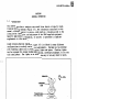
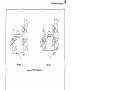
Figure 1-1.
,.
Typical Grade crossing warning System
iv
UNION SWITCH & SIGNAL
SECTION I
GENERAL INFORMATION
1.1
INTRODUCTICN
This manual provides a complete overview of Uni<Xl Switch & Signal's Grade
Crossing Warning Systems (Figure 1-1). The information contained in this
manual, although general in nature, can be used as a valuable guide in the
installaticn, operation, and maintenance of the US&S supplied- equipment.
Specific application infomation, if required, is presented in separate
supplements to this manual.
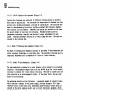
Grade Crossing warning equipment (Figure 1-2) is offered in many different
configurations to satisfy various site requirements. Systems can be provided
with flashing lights only or with flashing lights and gates. Flashing lights
can be arranged for nocnal highway applications, converging highways, or for use
with cantilevers. The lights can be either cne-way or two-way (back to back).
~BELL
FLASHING
SIGNAL LIGHT
ASSEMBLY
GATE
MECHANISM
GATE ARM
FLEXIBLE CONDUIT
WITH SEALTITE
FITTING
---...-i
JUNCTION BOX
BASE
Figure l-2.
----7~ \
Grade Crossing Warning Assembly with Gate
5958, p. l-l.
m
m
UNION SWITCH & SIGNAL
Different control schemes are also available. These range from the very basic
for use at industrial sidings, such as our AW-10 Area Directional Warning
System, to our very so~isticated MM-25 Motion Mcnitor equipment.
1.2
1.2 .l
EQUIPMENT DESCXIPTICtil
Flashing Light Assembly (Figure l-3)
Flashing light assemblies consists of a XA-120 Junction Box Crossarm on which
are mounted the flashing light units. The flashing light units are either the
standard BC-100 (8-3/8" lens) or for increased light output the HC-120A (12"
lens). Assemblies are available for 1-way am 2-way (back-to-back) applications
and for use -with crossing assemblies equipped with fiberglass, aluminum or wood
gate arms, am for cantilever installations. The light units are equipped with
a hood and either the standard 20" background or the 24" background (HC-120A
Unit Only).
1.2.1.1
HC-120A Flashing Light Unit (Figure l-3)
· The HC-120A Light Unit is constructed of aluminum with stainless steel hardware,
and utilizes a 12 • deep dish paabolic ref elector with a 12" red Lex.an R
roundel. The reflector is center mounted for easy replacement. The roumels
o:>me in different beam spread aid deflection combinations. Therefore, when
replacing a roundel in the field, it is important that it is replaced with one
of the same kind. The cover, which is secured by a bolt that accepts the AAR
terminal wrench, swings open to provide easy access to the interior for changing
the lamp, interior cleaning, or other maintemnce. ·
The lamp socket is brass plated and its mounting allows for X, Y, Z axis lamp
location adjustment. The socket accepts 10 or 25-watt, 10-volt S-11 lamps1
25-watt 110-volt G-16-1/2 lamps, or 10-volt 16 or 36-watt Quartz-Iodide lamps.
Voltage reading can be taken at-the bulb for battery adjustments.
The light unit has a standard l-l/4" straight pipe threa:l suitable for mounting
the unit to all type crossaxms.
1.2 .1.2
BC-100 Light Unit (Figure l-3)
The HC-100 Light Unit is constructed of aluminum for lcng service life am easy
maintenance. It is equipped with a standard reflector and 8-3/8" roundel. The
roundels are available in red Lexan R or red plexigl.ass, am yellow glass for
special applications. Rourdels cane in diffe~ent beam arw::'l spread canbinations.
Therefore, when replacing a roundel in the field, it is important that it is
replaced with one of the same kind. The cover swings open for easy access to
the interior for lamp replacement and other maintenance. The lamp h:>lder is
also 3-axis (X, Y, and Z) adj us table and uses the same lamps as the BC-120A
Light Unit described in paragraph 1.2.1.l.
5958, p. 1-2
UNION SWITCH & SIGNAL
XA-120
JUNCTION BOX
CROSSARM
BACKGROUND
HOOD
HC-120A
LIGHT UNIT
ONE-WAY FLASHING LIGHT ASSEMBLY
HC-120 LIGHT UNIT
Figure 1-3.
HC-100 LIGHT UNIT
Flashing Light Assembly
5958, p. 1-3
m
m
UNION SWITCH & SIGNAL
XA-120 Junction Box Crossarm (Figure 1-3)
1.2.1.3
Junction Box Crossarms are available in different configurations to provide a
wide range of applications. The crossarms are constructed of aluminum for 1oog
service life, minimum maintenance, and ease of installation. 'lhe junction box,
used for intercx>nnecting the wiring, cx>ntains standard AAR. terminals <X>lllplete
with terminal nuts and washers. Removable end plates are provided on the arms
for easier access to the wires for stringing. Threaded elbows allow for
irdependent horizonta1 (azmiuth) and vertical (range) adjustments of each
signal. Attaching hardware consists of a U-bolt clamp and nuts. The nuts are
located in the junction box.
1.2.2
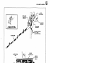
Model 75 Crossing Gate Assembly (Figure 1-4)
The Model 75 Crossing Gate Assembly consists of the Model 75 Gate Mechanism and
either aluminum, fiberglass, or wood gate arms. The autanatic crossing gate is
canpletely adjustable and is adaptable to 2 wire or 3 wire circuitry.
1.2.2.1
Model 75 Gate Mechanisn
(Figure 1-4)
The gate mechanism is mounted en a steel chassis, and is housed in an aluminum
enclosure. The mechanisn ex>mes either with the DN-22A relay for 2 wire control
circuitry or without for 3 wire control circuitry. '!be Gate is locked into the
clear position by an electromagnetic brake. If the power fails, the gate arm
drops to the horizontal.
The mechanism ex>nsists of the following: a permanent magnet de electric motor,
which requires a naninal 12-vo1t power supply, driving through a 115:1 gear
reduction train7 a hold clear unit (sanetimes called electric brake) which is
located <X'l the ootor amature shaft1 and a circuit controller assembly, which
has four contacts operated by a cam. Two circuit controller contacts are wired
for mechanism control and two contacts are available for controlling external
circuits, such as the bell and. the clear position repeater relay. Caitacts
lB..;.lC and 2B-2.C are adjustable £ran 70 to 93 degrees.
Rubber bumpers are provided at 0- and 90-degree positioo.s of the mechanism. A
stop bolt is used in the top bumper to adjust the gate am posi ticn when the arm
is horizontal.
The splined en:is of the main shaft exten:i out both sides of the mechanism for
mounting the cast aluminum ann supporting members. 'l'he counterweights are
attached to these supporting members and the support bracket for fiberglass,
aluminum, or wooden arms. The tota1 weight of the operating mechanism a1one is
approximately 225 pounds.
To facilitate mainterance, torqie readings can be taken directly off the main
shaft, an::i the gate ar:m can be manually cranked up or down. Also provided is a
power cut-out link which cuts internal power to the mechanism without affecting
power to the bell, arm lights, or signal flashers.
5958, p. 1-4
UNION SWITCH & SIGNAL
GATE
MECHANISM
'COUNTER
WEIGHTS
GATE ARM ADAPTER
FOR WOOD GATE ARMS
GATE ARM
SUPPORT
FLEXIBLE CONDUIT
,.....,_ _ , WITH
SEALTITE FITTING
CIRCUIT
CONTROLLER
MOTOR
CONTROL
RELAY
'
t
f.i
~
MOTOR
Figure 1-4.
HOLO
CLEAR
UNIT
Model 75 Crossing Gate Assembly
5958, p. 1-5
m
UNION SWITCH & SIGNAL
1.2.2.2
Gate Arms (Figure 1-4)
Gate arms are either wood or telescoping aluminum or fiberglass. US&S does not
provide wood gate arms. The telescoping aluminum gate arm consists of three
sections of extruded aluminum. The telescoping fiberglass gate arm consists of
the first section of extruded aluminum, and the second and third sections of
pultruded glass rein:fored polyester thermoset (fiberglass). Both cane in
adjustable lengths from 17 to 40 feet.
To warn on-coming veh:icular traffic, three 10-vol t weatherproof bi-directional
4" or 7" lights are mdtlnted on the arm. Each is plug connected to the main
harness. A plug connector is provided in the wiring harness between the first
and second arm sections to facilitate arm replacement. Another plug connector
is located between the gate arm and the mechanism. Additional warning is
provided by the alternate Scotchlite reflective red and reflective white
sheeting on the arms.
The gate arm is linked to the support assembly by a shear pin which helps to
prevent mechanism damage if the arm is struck.
1.2.2.3
Counterweights (Figure 1-4)
Counterweights are supplied to suit each corresponding length of the gate arm.
The weights are approximately the same for both fiberglass and aluminum arms.
The weights are secured to the gate support arm supports with bolts and nuts.
This allows for moving the counterweights forward or backward for proper gate
arm balance and operation.
1.2.3
Bell Unit (Figure 1-5)
The bell unit is a Model BA-10 with a 12-inch steel gong mounted on a cast
aluminum housing with a rain hooti. A hinged aluminum cover is provided for easy
access to the operating mechanism. The operating mechanism is a rotary solenoid
driving a clapper. The solenoid is sealed against dirt and foreign material and
requires no lubrication. Operating voltage is 10 Vdc, producing a sound level
of 105 - 113 dbA at 180 - 190 strokes per minute.
1.2.4 Masts (Figure 1-2)
Masts for grade crossing warning assemblies come in two lengths; 13 1 6" and
15 '3". The 13 '6" mast is used in standard installations, while the 15 '3" mast
is used for converging highway applications •. On the 15'3" mast, an additional
hole is drilled at the appropriate degree from center to accommodate the
additional crossarm.
Masts are constructed of aluminum for easy handling, long life, and minimum
maintenance. Both 4" and 5" diameter masts are available. In general, the 5"
diameter mast is used when the grade crossing warning assembly is equipped with
automatic gates. Refer to Section VI for additional data, including ordering
information.
5958, P• 1-6
UNION SWITCH & SIGNAL
1.2. 5
Junction Box Base (Figure 1-2)
Aluminum Junction Box Bases are available for both the 4° an:i 5° diameter mast.
They are used to support the mast and for terminating underground cable and for
making circuit connnectioos. Bases oome with either U or 24 MR terminals,
depending en application. A plain clamp base is also available for the 4°
diameter mast. Refer to Section VI for addi tiooal data, including ordering
infonnation.
1.2.6
Signs (Figure 1-2)
Grade crossing warning signs are made of aluminum arrl include all hardware
necessary for mounting. Signs are provided either in engineering grade
Scotch-Lite R or Hi-intensity reflex-reflection, and oonfom to AAR
requirements. The signs are: Railroad Crossing, Tracks, and Stop on Red
Signal. Refer to Sect.ion VI for additiO!lal data, including ordering information.
1.2. 7
Equipment Cases (Figure 1-6)
F,quipment cases, located at wayside are provided in different sizes to
accanmodate the control equipment and ancillary items. They include the train
detection equipment, plug-in relays, batteries, power supply components, am
miscellaneous. These cases, constructed fran Cor-Ten Steel, are provided with
front arrl rear full size locking doors. Provisions are made for shelves and
backboard.
1. 3
CONTR:>L CIRCUITS
Stamard rx::, AC/DC, AFO (Audio Frequency Overl.ay), Righ Frequency am Motion
Monitor track circuits are used to provide train detection for grade crossing
warning control systems. To properly maintain the system, it is important to
know what type of track circuit is used. For information on the different
control circuits, refer to Section IV.
Figure 1-5.
Crossing Bell
5958, P• 1-7
w
UNION SWITCH & SIGNAL
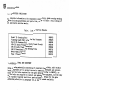
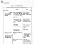
1.4
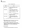
SUPPORTING PUBLICATIONS
For complete information on the components comprising a grade crossing warning
system including maintenance and parts list, refer to Table I for a listing of
all appli.cable service manuals.
Table I.
List of Service Manuals
Model 75 Crossing Gate
Flashing Light Unit w/Jtmcti.on Box Crossarm
BA-10 DC Aluminum Bell
AFO-IIC Audio Frequency Overlay Track Circuit
ATT-20 Audio Track Tranceiver
AW-10 Directional Area Warning Device
1't1-25 Motion Monitor
Type C Track Circuit
1.5
SM6043
SM6326
SM6094
SM6134
SM6299
SM6133
SM6252
SM6120
MATERIAL, TOOLS AND EQUIPMENT
Normal cleaning materials consisting of clean lint free cloths, soft bristle
brush, compressed air in aerosol can and a commercial detergent and solvent.
Other than the tools required for the gate mechanism (refer to SM6043) , no
special tools are required to install and maintain the equipnent, and the only
test equipment required would be a good multimeter. Grease for the gate
mechanism, called for in paragraph 5.2. 3, should be made available.
5958, P• 1-8
UNION SWITCH & SIGNAL
VITAL
RELAYS
LIGHTNING
ARRESTERS
TRAIN
DETECTION
UNIT
TRANSFORMER
TERMINALS
BATTERIES
Figure L-6.
Typical Grade Crossing Control Equipment Case
5958, p. 1-9/1-10
m
UNION SWITCH
a SIGNAL
SECTION II
APPLICATIONS
2 .l
GENERAL
Grade Crossing Warning Systems can be applied anywhere a highway crosses a
railroad. The type of equipment installed, aoo the type of control used is
depen::lent upon many factors. For example; because of the terrain a cantilever
may be required, or warning lights for converging highways may have to be
installed. In certain areas, warning gates may also be required. When planning
a grade crossir¥3 warning system all factors must be considered.
The train detectioo track circuit aoo control circuits must also be determined.
For example: in coded track circuit territory, AFO equipment should be used.
Where train traffic involves frequent stop, restart aoo reverse movements,
motioo monitor control is recamnended. Section IV provides a brief description
of the different controls available. For detail information, refer to the
applicable service manual listed in Table I.
Because of the many variables, it is not practical to cover all the applicatioos
possible in this manual. For the equipment and controls that apply to a
specific locatiai, refer to the applicable layout drawings and circuit diagrams.
5958, p. 2-1/2-2
m
UNION SWITCH & SIGNAL
SECTION III
INSTALLATION
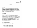
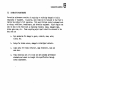
3.1
GENERAL
The plans and circuit diagrams developed for the specific location must be
followed when installing a Grade Crossing Warning System. The following data
are provided to guide in the proper planning and installation of the equipment.
All equipment must be installed in accordance with rules and regulations imposed
by municipal, state, and federal government agencies.
3.2
PRE-PLANNING
Because of the many variables involved, a site survey is recommended to
determine the specific system to be installed. Table II is a typical site
survey check list that can be adopted to suit particular needs. Upon completion
of the survey, a plan should be made to show the location of all components and
the sources of power. Based on this plan, a cabling diagram can be developed
showing the length of cable runs between components and track, and the number of
wires required for each cable. Information to be considered in a survey is
covered in paragraphs 3.2.1 and 3.2.2.
3.2.1
Cable and Wire Requirements
Recommended cable and wire requirements are as follows:
a.
No. 8 AWG in lengths of less than 50 feet.
b.
No. 6 AWG in lengths of 50 feet to 120 feet.
c.
Wire size would be proportional for longer lengths.
d.
For track circuit connectors use 1-conductor No. 8 AWG underground
cable, non-metallic sheath.
e.
For connections to signals use 5-conductor No. 9 AWG underground cable,
non-metallic sheath or single conductor No. 10 AWG underground.
f.
For wiring signal units use 1-conductor No. 14 AWG flexible wire,
3/64-inch wall insulation, neoprene compound sheath, or equivalent.
g.
For bonding track circuits use the Cadweld rail head type (or
equivalent).
h.
Track circuit bootleg connections and track rectifier connections are
Tigerweld 1S-1 bond wires with 3/8-inch terminal on one end, other end
tinned, 36-or 42-inch in length (or equivalent).
1.
Ground wire is No. 6 AWG.
· 5958, p. 3-1
m
UNION SWITCH & SIGNAL
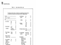
Table II.
Site Survey Check List
The following .is not meant to portray a complete site survey questionnaire but is typical of some
of the information that will be found on a site survey that will aid in installation planning.
Customer
11. Standby power
required:
Location of Installation
Date
1. No. of Tracks
2. Type of Operation:
If Automatic:
3. Type of Highway:
Traffic
A. Battery:
Single
D
Double
Other
0
0
Automatic
Manual
Area Warning
Directional Control
0
0
0
0
One Way
Two Way
0
0
4. Maximum speed of
fastest train in mph
5. Train switching or
stopping in
approach zones:
6. No. of train
movements per day
over crossing
Yes
No
7. Within the control
limits:
Switches T or F
Train Signals
Track bonded
Metal guage rods
D
D
1 2 .Track Ballast
Condition:
13. Highway at crossing:
Wood
Steel
Concrete
Other
DC
AC
Voltage
Frequency
5958, p. 3-2
0
D
2ohm
5 ohm
Sand
Other
Width
0
0
0
0
14. Crossing Signals
located at:
Sides of street
Center of street
Other
15. Signals/Gates:
Signal with 2 units
Signal with 4 units
Cantilevers
16. Bells required:
D
D
D
D
D
D
D
D
required
0
D
D
18. Track circuits :
DC
AFO
Type 'C'
0
0
0
Motion Monitor
D
Yes
No
L...:
0
D
D
0
Yes
No
No.
0
0
0
Crossbuck
SORS
Tracks
0
L.....,
D
0
17. Signs required:
0
0
n
D
0
ft.
Lights on main masts
Gates (Length)
"No Turn" Light
4 hole joints
6 hole joints
10. Power available at
crossing:
Yes
No
Angle
8. Rail Section
9. Ties
No
0
0
Yes
19. Cases factory wired:
w
..
UNION SWITCH Ii SIGNAL
3.2.2
Standards/Equi.pnent Location Data
Following is a general list of standards and location data that should be
observed in developing a layout plan for the site. Figure 3-1 and 3-2
illustrate typical location plans.
a.
Width and surface of roadway at grade crossing should correspond to that
of the adjoining highway and have the same number and width of traffic
lanes as the adjoining highway without extra l~es at the crossing.
b.
The center of the foundations should be six feet from the edge of the
curb or roadway, and no closer than 12 feet from the center of the
closest track. (See Figures 3-1 and 3-·2.)
c.
Foundations shall be placed so that the signal assembly is square with
the highway, regardless of the angle of the crossing. (See Figure 3-2.)
d.
The top of all highway crossing signal foundations shall be 6 inches
above the crown of the highway (see Figure 3-3).
e.
Location of control cases and far end approach cases should be
determined by accessibility of AC power and circui.t design of the
installation.
f.
The location of bootlegs and other track connections are usually
determined by the particular standards of each individual railroad.
3. 3
3. 3.1
SITE PREPARATION
Excavation
Excavation is required for foundations and underground cable trenches.
Foundation requirements are covered in the following paragraphs. Cable trenches
and holes for pedestal mounted junction boxes and bootlegs are dictated by local
conditions and individual railroad standards. Follow normal installation
procedures •
3.3.2
Signal Mast Foundations
Figures 3-4 and 3-5 provi.de details of poured aoncrete foundation for grade
crossing masts. Figure 3-4 is for aluminum signal. masts proposed for grade
crossing warning systems with gate installations which have 11-11/16" x
11-11/16" bolt spacing at the base. Figure 3-5 is for aluminum signal masts
which have 9-1/2" x 9-1/2" bolt spacing at the base. Precast foundations may be
used in place of the poured foundation provided the correct bolt spacing is
avai.lable. Information for precast foundations is shown in Figures 3-6.
5958, p. 3-3
m
UNION SWITCH & SIGNAL
TRACK
<t.
EDGE OF PAVEMENT
PLAN
<i_ PAVEf\4ENT
·---
t' --12·~
MIN.
.
~'o-1
I
i o s·
I
I
--
'
-
-
I
I
I
'r -I-~ ~
e·
~12·
MIN.
EDGE OF PAVEMENT
H
<r.
TRACK
Figure 3-l.
Typical Location Plan for Highway Crossing
Signals With or Without Gates for Two-way
Highway Traffic (Right Angle)
EDGE OF PAVEMENT
ct_
PAVEMENT
PLAN-·
· •
EDGE OF PAVEMENT
Figure 3-2.
sg.ss,
p. 3-4
Typical Location Plan for Highway Crossing
Signals With or Without Gates for Tw:>-way
Highway Traffic (Acute Angle)
UNION SWITCH & SIGNAL
20"/24"
7'MIN.
TOP OF FOUNDATION
6" ABOVE CROWN OF
HIGHWAY
Figure 3-3.
3.3.3
Foundation Height
Cantilever Foundations
Details of concrete foundations for cantilevers depends on the type cantilever
used. This information will be detailed on the applicable plans.
3.3.4
Control Case Foundations
Cast iron piers are generally used with cases, but precast foundations can also
be used. Some amount of excavation is required for both types.
3.3.5
Trenching for Cables
a. Use of a trencher or backhoe is recommended f'or a more uniform depth and
direction.
b. Cables should be laid at a depth of 30 inches unless conditions or local
regulations mandate otherwise.
c. Cables, in most instances, can be fed under roadways by using a "driving
pipe".
d. If this is impractical, the roadway must either be torn up, or cables
strung overhead.
5958, p. 3-S
m
UNION SWITCH & SIGNAL
A suggested poured concrete foundation for junction box bases with 11-11 /16" x 11-11 /16"
bolt spacing is shown below.
TRACK SIDE
i - . - - - - - 2 · 1 0..
------I
1 2 · 1 1 2 " - - - - 4-1/2"
4·1/2'" -1.-..i--12-112''
1---1----1---+--I- 5-27/32"
1"'
4-112..
5-27/32"'
12·1/2"
I>
i
11-11/16"
2'10"'
%
4·1/2"
FRONT
DOOR OF CROSSING GATE MECHANISM CASE ON THIS SIDE
LOCATION OF 2·1/2" DIAMETER
HOLE IN TERMINAL
COMPARTMENT BASE
3-114"
I
8"
IJ
II
It
11
II
....
..
11
II
18" BELOW GROUND
LEVEL OR TO SUIT
LOCAL CONDITIONS
'ff
TOP OF RAIL OR
11
It
3'6" MINIMUM
TO BE DETERMINED BY
GROUP,10 CONOITIOP,!S
II
II
!.!
CHASE
CHASE 4"•8"
0
FOR MULTIPLE OR SIMILAR
CABLE
MATERIAL
18
9
4.5
4
· Cu. Ft. Stone
• Cu. Ft. Sand
Bags Cement
Concrete Mixture
1-2-4
Foundation Bolts
with Hex Nuts and
Washers.
Figure 3-4.
5958, p. 3-6
NOTES
A · Dimensions of chase may be varied to suit number
of electrical conductors.
Fibre or steel conduit of suitable diameter may be
substituted for chase.
B · Refer to ordering reference for foundation bolt
size and part number.
Poured Concrete Foundations For Flasher
Signals With Autanatic Gates
UNION SWITCH & SIGNAL
Suggested concrete foundations for clamp bases or junction box bases with 9-1/2" x 9-1/2" bolt spacing are shown below.
JUNCTION BOX BASE
PLAIN CLAMP BASE
HIGHWAY SIDE
,._.....__.,... 4-3/4"
- - -............. 4-3/4..
4-1/2..
4-3/4"
,o..
2'5"
w
10" ~
0
t;
! ~::c
10"
2'5"
+~
• it
I :c
£!
10" Cl
::c
i
LOCATION OF 2·1/2"
HOLE IN TERMINAL
COMPARTMENT BASE
4-1/2..
4·1/2"
'
4-1/2.. _..,...._ _
10"______ 4-1/2"
4-1/2" - - - - - 1 0 "
- - - - - - 4-1/2"
,._..._ _ _ _ 2'5.. _ _ _ _....
-----2'5"------<""1
I
2-1/4"
6" ABOVE TOP OF RAIL
OR TO SUIT LOCALITY
2-1/4"
t
. }l
1"
3'0" MIN. TO BE
DETERMINED ev
GROUND CONDITIONS
•\\ ~
I '\"""
4"µ1,\
I
I
l:
II
J.I\\
n
II\'\
\
11
11
'L
II
/ -t -...... c-''
_.,
c
I
I
I
"'
II\
\
.
}.
18" BELOW GROUND LEVEL OR
TO SUIT LOCAL CONDITIONS
2' BELOW GROUND LEVEL OR
TO SUIT LOCAL CONDITIONS
FOR MULTIPLE OR SIMILAR CABLE
ARRANGEMENT WITH TERMINAL BOX LOCATED
OPPOSITE SIDE FROM TRACK
NOTES
MATERIAL
12.5 · Cu. Ft. Stone
6.25 • Cu. Ft. Sand
3.12 • Bags Cement
Concrete Mixture 1-2-4
• Foundation Bolts 1" x 24" with
4
Hex Nut and Washer.
Conduit as required. See Note A.
Figure 3-5.
FOR MULTIPLE OR SIMILAR
CABLE
A • Dimensions of chase ma':' be varied to suit
number of electrical conductors.
Fibre or steel conduit of suitable diameter may
be substituted for chase.
B · Foundation to be placed square with the highway regardless of the angle of the crossing.
C • Refer to ordering reference for foundation
bolt size and part number.
Poured Concrete Foundations For Flasher Signals
5958, p. 3-7
m
m
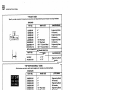
UNION SWITCH & SIGNAL
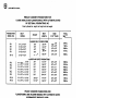
PRECAST CONCRETE FOUNDATIONS FOR
FLASHER SIGNALS AND FLASHER SIGNALS WITH AUTOMATIC GATES
BY SECTIONAL FOUNDATIONS, INC.
Order by Model No., height, bolt length and total weight.
FOUNDATION
MODEL NO.
BOLT
CENTERS
SF-1
SF-1
SF-1
SF-1
9-1/2" x 9-1/2"
9-1 /2" x 9-1/2"
9-1/2" x 9-1/2"
9-1 /2" x 9-1 /2"
2'6"
3'6"
4'6"
5'6"
SF-1X
9-1/2" x 9-1/2"
4'7-1/2"
HEIGHT
BOLT
LENGTH
BASE
3-1/2"THICK
TOTAL
WEIGHT
32-1/4"
44-1/4"
56-1/4"
68-1/4"
30.. x 30"
30" x30"
30" x 30"
30" x 30"
544 lb.
7021b.
8061b.
910 lb.
58-1/4"
30" x 30"
8601b.
44-1/4"
56-1/4"
68-1/4"
80-1/4"
92-1/4"
104-1/4"
30"x 30"
30" x 30"
30.. x 30'"
30" x 30"
30" x 30"
30" x 30"
1096 lb.
1293 lb.
1490 lb.
1686 lb.
1882 lb.
2078 lb.
44-1/4"
69·1/4"
30" x 30"
30" x 30"
9961b.
1368 lb.
FLASHER ONLY FOUNDATIONS
FLASHER AND GATE FOUNDATIONS
SF-2
SF-2
SF-2
SF-2
SF-2
SF-2
11-11/16" x 11-11/16"
11-11/16" x 11-11/16"
11-11/16.. x 11-11/16"
11-11/16"x 11-11/16"
11-11/16" x 11-11/16"
11-11/16.. x 11-11/16"
3'6"
4'6"
5'6"
6'6"
7'6"
8'6"
SF-2X
SF-2X
11-11/16" x 11-11/16"
11-11/16" x 11-11/16"
3'6-1/2"
5'7-1 /2"
PRECAST CONCRETE FOUNDATIONS FOR
FLASHER SIGNALS AND FLASHER SIGNALS WITH AUTOMATIC GATES
BY PERMACRETE PRODUCTS CORP.
Order by Model No., height, bolt length and total weight.
FOUNDATION
MODEL NO.
BOLT
CENTERS
HEIGHT
BASE
3-1/2" THICK
BOLT
LENGTH
TOTAL
WEIGHT
FLASHER ONLY FOUNDATIONS
S-1
S-1
S-1
S-1
9-1/2" x 9-1/2"
9·1 /2" x 9· 1/2"
9-1 /2" x 9-1/2"
9-1 /2" x 9-1/2"
2'6"
3'6"
4'6"
5'6"
32-1/4"
44-1/4"
56-1/4"
68-1/4"
.
30" x 30"
30" x 30"
30"'x 30"
30" x 30"
544 lb.
7021b.
8061b.
910 lb.
30" x 30"
30" x 30"
30" x 30"
30" x 30"
30" x .30"
30" x 30"
10961b.
1293 lb.
14901b.
16861b.
1882 lb.
20781b.
FLASHER AND GATE FOUNDATIONS
S-2
S-2
S-2
S-2
S-2
S-2
11-11/16" x 11-11 /16"
11-11 /16" x 77-11 /16"
11-11/16" x 11-11 /16"
11-11 /16" x 11-11 /16"
11-11 /16" x 11-11 /16"
11-11/16" x 11-11/16"
3'6"
4'6"
5'6"
6'6"
7'6"
8'6..
Figure 3-6.
59 511~ p. 3-8
44-1/4''
56-1/4"
68-1/4"
80-1/4"
92-1/4"
104-1/4"
Precast Foundations
UNION SWITCH & SIGNAL
3.3.6
Backfilling and Grading
a.
Backfill of trenches should not be done until a "megger" has been used
on the cables to ascertain there is proper continuity and no crossed or
exposed wires.
b.
"Pull" concrete forms.
c.
Fill and grade level.
d.
Tamp fill thoroughly, especially around signals equipped with gates and
cantilevers.
3.4
INSTALLATION PROCEDURES
This section describes the general procedures for installing the components of a
Highway Grade Crossing Warning System. If more detailed information is
required, consult the individual service manuals which are provided with each
major component (refer to Table I).
NOTE
If preferred, with the exception of the gate mechanism and
gate arm, the equipment may be assembled and mounted on the
mast while on the ground and raised into its final position
on the foundation. Make sure that all components are
properly aligned to the road, etc. before raising in place.
3. 4. 1
Installation of Plain Clamp Base and Mast
NOTE
Mast and base ar·e usually received as an assembly.
a.
Feed the cables from the chase through the center of the base, up the
mast and out the pre-drilled crossarm hole. Position the base on the
foundation bolts. Check that the pre-drilled hole for the crossarm is
correctly oriented.
b.
Install nuts on foundation bolts and hand tighten.
c.
Use a level and check all sides of the mast to ascertain that the mast
is plum. (If not, shimming is required.)
d.
Securely tighten all foundation bolt nuts.
5958, p. 3-9
m
m
UNION SWITCH & SIGNAL
3.4.2
Installation of Junction Box Base and Mast
a.
Open the access cover at the junction box base and feed the cable fran
the chase through the junction box opening. Position the junction box
base and mast on the foundation bolts. Check that the pre-drilled hole
for the crossarm is correctly oriented.
b.
Install nuts on foundation bolts and hand tighten.
c.
On the mast, feed a cable through the pre-drilled hole for the crossarm
to the junction box base.
d.
Use a level and check all sides of the mast to ascertain that the mast
is plum.
e.
3.4.3
(If mt, shimming is required.)
Securely tighten all foundation bolt nuts.
Installation of Junction Box Crossarm
NCY!'E
The light units may be fastened to the junction box
crossarms am pre-wired when received. If not, they may
be mounted to the junction box crossarm before installing
the junction box crossarm, or installed after the
junction box crossarm is mounted (refer to paragraph
3.4.4.).
a.
Open the junction box cover en the crossarm by loosening the two bolts
am swinging the cover open.
b.
Remove the U-bolts ard temporarily place them aside.
c.
Lift the crossarm into position and feed the cable protruding fran the
mast into the junction box outlet. Position the crossarm on the mast
with the back of the junction box aligning with the pre-drilled hole in
the mast.
d.
Install U-bolt, nuts, am tighten securely.
lbs.
e.
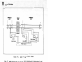
Ccnnect the cable to the terminals as shown in Figure 3-7.
f.
Close and secure the junction box cover.
3.4.4
Torque U-bolts to 70-90 ft.
Installation of Light Units
Both the HC-100 ard HC-l20A Light Units are installed in the same manner.
3.4.4.l
a.
Installation Procedure
Open the jtmction box cover on the crossarm by loosening the two bolts
ard swinging the cover open.
5958, p. 3-10
UNION SWITCH & SIGNAL
b.
Ranove the elbow from the crossarm bracket and fasten to the light unit.
c.
Carefully feed the pigtail from the light unit through the bracket and
through the arm to the junction box. End plates on the arms may be
removed to facilitate stringing the wires. A fish tape may al.so be
helpful.
NOTE
If extension arms need to be attached, signal light
brackets must be removed from junction box assembly.
Remove the four screw nuts and washers that secure the
signal light brackets to jtlllction box assembly.
Brackets can now be removed. Align the four holes in
the extension arm cover plate with the holes in the
jtlllction box assembly, making sure that the gasket is
between these two pieces. Install the four screws.
Slide gasket and signal light bracket or an extension
arm (whichever is required) onto the screws. Install
the t'our washers and nuts.
Remaining brackets must now be installed. Align the
t'our holes in the cover plate of signal light bracket
with the holes in extension arm cover plate. Make sure
gasket is between these two pieces and install screws,
washers, and nuts.
At this point, it is best to have arranged a fish wire
or fish string through the crossarm and any extensions
there might be so that the signal unit with elbow
attached can be assembled to the remaining part of the
crossarm unit as the fish wire is tied to the lamp
pigtail and pulled through to the junction box.
d.
Secure the light unit to the bracket. Loosen the set screws on the
elbow and position light unit to its approximate final position. Repeat
for all other light units.
e.
Canplete wiring by attaching leads to terminals in accordance with
Figure 3-7.
f.
Secure junction box cover.
g.
If crossarm end plates were removed, replace and secure with attaching
hardware.
h.
Align the signal light units in accordance with paragraph 3.4.4.2
following.
5 958, p • 3-11
m
UNION &WITCH & SIGNAL
RIGHT _..._
COMM
COMM.
__;,,.;;._
_ _ _ ___,
LEFT
LIGHT
L+
LIGHT '-."'----A_+_ _ ___,
I
CROSSARM - - ,
JCT BOX
I
LEFT
LIGHT
COMM.
COMM.
L+
R+
a:
i . .,
8
RIGHT
LIGHT
R
'L
L
A
>
i!:2
J:
4 UNIT SIGNAL
COMM.
COMM.
LEFT
___..._ _ _
L+____;...., SIGNAL
I
CROSSARM - - JCT BOX
2'-..!:!!...-2..
L _
--f-11-+
TRAFFIC DIRECTION
>
R
L
~~
S
JCT BOX
:i:
MAST
2 UNIT SIGNAL
Figure 3-7.
3.4.4.2
Signal. Lamp Wiring Diagrams
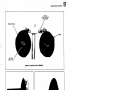
Light Units Alignment (see Figure 3-8)
Vertical adjustment should be made first with the horizontal adjustment tightly
clamped so that unit wiggling does not cause a bad vertical adjusbnent. A
sighting tube (Nl70622) can be used to aid in the initial adjustment. The final
adjustment should be checked by an observer on the road, safely •
AAR Signal Manual Part 268, 1972 Revision is repeated he-rein as a Guide to
Signal Unit Alignment.
simplicity sake •
Sane sentences of manual Part 268 are omitted for
ALIGNING HIGHWAY CROSSING SIGNAL REFLECl'OR 'l'lPE LIGHT UN:ITS
(REVISED SIGNAL MANUAL PAR!' 268)
a.
The aligning
instructions
afforded for
be exercised
5958, p. 3-12
of electric light units in accordance with these
must not be started until proper protection has been
highway and pedestrian traffic. When aligning, care must
that no unsafe conditions are set up.
UNION SWITCH & SIGNAL
•
-
Jso
HC-120
HC-100
Azimuth (Horizontal) Alignment
--1~
!
AS REQUIRED
,....,,_____.__;,,_,
HC-120
HC-100
Range (Vertical) Alignment
Figure 3-8.
Light Unit Alignment
5958, p. 3-13
UNION SWITCH & SIGNAL
(1) The lamp receptacles are positioned and sealed by the manufacturer,
using 1/64 inch precision based lamps. To obtain the range and
efficiency intended, signal precision lamps must always be used in
the light units.
(2) When aligning of light units has been canpleted, tests must be made
immediately to determine that the equipnent functions as intended.
b.
Procedure is as follows:
(1) Front Light Units
(a)
(b)
(c)
(d)
Ce)
(f)
Continuously light one lamp.
Open door wide so clear beam is displayed.
Adjust light unit vertically to align axis of beam five feet
six inches above pavement at selected alignment distance. Both
lamps should be aligned to same point.
Adjust light unit horizontally to align axis of beam to center
of approach lane in approach to signal at selected alignment
distance, maintaining vertical alignment.
Tighten clamps and close door.
Repeat instructions for other front light units.
( 2) Back Light Units Where Used
(a)
(b)
(c)
(d)
(e)
(f)
Continuously light one lamp.
Open door wide so clear beam is displayed.
Adjust light unit vertically to align axis of beam five feet
six inches above pavement at a point 50 ft. in approach to the
signal on opposite side of track.
Adjust light unit horizontaJ.ly to align axis of beam to a point
50 feet with symmetric patterned roundels, 150 feet with
non-symmetrical roundels in approach to the signal on opposite
side of track and in center of approach lane, maintaining
vertical alignment as in Instruction (2)(c).
Tighten clamps and cJ.ose door.
Repeat Instructions for other back light units.
(3) After units have been aligned, clamps tightened and doors closed,
they must be checked with lights flashing and lamps burning at
recommended voltage to make certain a flashing light aspect is
visible within a range of 1,000 feet.
NOTE
Torque on 3/8" U-bol t nuts of the crossarm elbows
shouJ.d be 15-20 ft .-lbs. Torque on 3/8" bolt which
holds J1m.ction box door should be 8-13 ft .-lbs.
c.
Assemble background and hood on each signal unit. Torque 110-32 screws
which hold background and hood in place to 1-2 ft.-lbs.
5958, P• 3-14
UNION SWITCH & SIGNAL
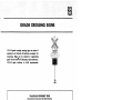
3.4.5
Installation of Bell or Pinnacle
NOTE
The bell or pinnacle slides over the top of the ma.st and
is secured by tightening one setscrew.
a.
String wires from crossar'lll junction box through the mast and out the
top.
b.
Position bell with face of gong parallel to the highway. Open back
of bell and feed wire to terminals. Attach wires to bell terminals
and position on top of ma.st.
c.
Tighten setscrew.
3.4.6
a.
3. 4. 7
Installation of Signs
Position the signs on the ma.st as shown in Figure 1-2 (or Section
VI), and secure with the hardware provided.
Installation of Equipment Cases
a.
Remove control case from shipping skid.
b.
Cut banding wire that secures ground pipe to bottan of case.
c.
Set control case in position on foundation, aligning parkway cable
with knockout in bottom of case. Secure to foundation with
appropriate hardware.
d.
Attach the "flower pot" or ground pipe coupler.
setscrews.
e.
Feed all cables (or rlres) through ground pipe into the case.
f.
Pack oakum into the pipe to seal it, and top with Johns-Manville "Dux
Seal" , or equivalent.
3.4.8
Tighten the
Installation of Relays
Shelf-mounted relays are shipped already installed in the case. For
installations using plug-in relays, the relays are shipped separately. These
relays should be carefully unpacked and plugged into their respective
locations. Keyed index plates prevent plugging the wrong relay in the wrong
location.
5958, p. 3-15
m
UNION SWITCH Ii SIGNAL
3.4.9
Installation of Crossing Gate Mechanism
Complete instructions for installing the Model 75 Gate Mechanism, crossing
gate arms, and counterweights are covered in Service Manual 6043. Refer to
this manual for detail instructions.
3.5
CONNECTING EQUIPMENT
Prior to installing the equipment, it should have been ascertained that all
cabling and wiring was completed. 'ro connect the various components of the
system, refer to the applicable installation diagrams.
3.5.1
Ringout Circuits and Cables
Ringing out a circuit simply means applying a "buzzer" or ohmmeter to the
open ends of the wire to check continuity. Each line should be checked prior
to hookup; then re-checked as units when they have been terminated.
3.6
ALIGNMENT AND ADJUSTMENT PROCEDURES
Generally, the alignment and adjustment to be accanplished upon canpletion of
installation include signal light units, grade crossing gate mechanism, track
circuits, and the lamp intensity. Alignment procedures for the light units
are covered in paragraph 3. 4.4.2. Complete alignment and adjustment
procedures for the other itans are contained in their respective service
manuals. Refer to these manuals (Table I) for these procedures.
3. 7
FIELD INSTALLATION RECORD
A permanent record of the installation adjustments, values, etc. for each
site should be made. An example of a form that can be used for this purpose
is· shown in Figure 3-9. When properly filled out, this form will be a
valuable aid in future servicing the equipment.
3.8
INSPECTION AND TESTING
3.8.1
Operational Test
To perform this test, track sections must be shunted at the battery or feed
end and at the relay end. A satisfactory shunt arrangement should be of O. 06
ohms resistance. A fifteen ( 1 5) foot length of 16 gauge insulated wire, with
ends soldered to files, provides an adequate shunt. While shunting, the
files can be scraped on the rail to assure good contact.
a.
Check all track circuits to see that the proper relay is being
controlled from its respective section. Shunting of the track
assures this, and in addition, it verifies that proper direction is .
being selected.
5958, p. 3-16
UNION SWITCH a SIGNAL
u•oON sw•TC:M .. SIGNAi. OIVISION
s-•••U• "'••' Off,ce.. 111tt.~.....,._ _.., 1s21a
UNION SWITCH & SIGNAi.
RECORD OF FIELD INSTALLATION OPERATING TESTS
CUSTOMER---------~---~
PROJECT _ _ _ _ _ _ _ _ __
GO _ _ _ _ _ _ _ _ _ _ _ _ LOCATION _ _ _ _ _ _ _ _ _ _ _ _ _ __
RTE. SHEET DWG. # _ _ __ CICT. DWG. # _ _ __
TRK. PlAN DWG. #
TEST:
HIGHWAY CROSSING WARNING SYSTEM:
or
systems being placed in service.
TRACK NO.
CONDITION
BALLAST _____
-- - ---
JOINTS _ - - - -
TYPE CONTROL
TRAINS/DAY
- --- --
BATTERY FULLY CHARGED
~
t
'l'
TI}tE: 3ETWEEN TRAINS
Min. _ _ _ _ ___ Hr.
:-tedian - - ___ Hr.
I Isl. ___ V.
I W(s ) ___ V.
SECOND. TABS
iOLTS AT SIGNALS
''A" ______ V.
CROSSING rnACTIVE
---- -
- - --
----
v.o.c.
E_(N)_ ___ MA.
A.
!sl·. ____ MA.
W(S) ____ AA.
CROSSI!!G- _ACTIVATED
- -- -
v.
A.
--- A.D·.C. - - A.A.C.
SENSITIVITY ADJ'US?=·!=
(AFO. !-1M-l0)
E(N}
.. ·f:J
"A"---see •• "B"- __ see.·
"A"- __ see.,, "B"-·-- see.
----- sec.
ra,
(a
TOTAL SIGNALS
Operate Time/Tra!
RECEDING CONTROL
(Crossing Clears after ;
From E(N)..:. - - See.
'l'ra:1n el~ars Road)
Train
MPH
From W(S) _ - - See. ____Speed
see., _____ Ft.
Train Speed ___ MPH
TIMING RELAY SET.
W(S)
( Mark Slot Positior
_APPROACH CONTROL
GATES TIME
~OWN:
V.A.C.
I
----- Second V.
O'P:
--- -
TRACK RELAYS
BATTERY CHARGER
------ v.o.c. ___ v.o.c. _ .:_ v.A.c.
'B" -
A.C. LINE
~
____ v.,l E(N) ___ V.
-RANSF.
To verity proper operation
- - - - - - sec.
GATE OPERATION
Down ___ sec. a!'ter signals
start
-
ATTESTED:
US&S REPRESENTATIVE
CUSTOMER REPRESENTATIVE
Figure 3-9.
DATE------DATE _ _ _ _ _ __
Reoo rd of Field Installation Operational Check
5958, p. 3-17
w
UNION SWITCH & SIGNAL
b.
Simulate the movement of a train by :first applying a shunt in the
approach section. This will start the bell ringing, the lights
flashing, and after 3-5 seconds flashing; cause the gate arm to
descend.
c.
With the first section still shunted, shunt the island circuit.
There should be no change.
d.
Shunt leaving section.
e.
Remove the first shunt. No change should take place. Remove the
island shunt. When the island shunt is removed, the gate arm should
assume its vertical position, the lights should stop flashing, and
the bell cease ringing.
f.
Leaving section is still shunted but no warning stick relay is
bridging track circuit down.
g.
When leaving section is clear, system should return to normal and is
ready for next move.
h.
Repeat this procedure, beginning at the opposite end of the circuit
and observe the fmctions as before.
3.8.2
Final Checkout
The final checkout of the system should include these points.
a.
Re-check the focus and alignment of the signal units.
b.
Measure the voltage of the lamp.
the lamp rated voltage.
c.
Check of the gate mechanism for proper operation.
d.
Check the discharge of the batteries with an ammeter and set the
rectifier for proper charging rate. This information is included
with the installation plans. Keep storage battery between 1215 and
1220 specific gravity (or as specified for the batteries used).
e.
External resistance in the battery circuits should be adjusted to
provide at the track terminals of the track relay the recanm.ended
working voltage of the relay.
f.
Make one last check of the site for items such as wire, which could
result in shorts.
g.
After all checks and adjustments have been made, turn on the entire
system and observe that all track relays are energized, the gate arm
is in the vertical position, and the lights and bell are not
functioning.
5968, P• 3-18
Voltage should be at lea:5t 85% of
UNION SWITCH II SIGNAL
SECTION IV
CONTROL CIRCUITS AND FUNCTIONAL OPgRATION
4.1
GENERAL
For most systen applications, all control equipment required to initiate highway
grade crossing warning is located at the crossing. Control packages designed
for Audio Frequency Overlay (AFO) track circuit applica~ion require additional
equipment at the approach end. AFO track circuits and motion monitoring track
circuits can be superimposed on existing direct current (de) track circuits or
applied separately in various combinations. The motion monitoring track circuit
is highly recommended in switching areas where frequent stop, restart and
reverse movements are made to minimize crossing down time. All controls for the
Motion Monitor are located at the crossing. The Type "C" track circuit scheme,
because of its high shunting sensitivity, is recommended for application at
difficult shunting areas. It is intended for use in non-signalled territory.
The type "C" track circuit is not suitable for overlay track circuit
application; therefore, it should not be used in a similar manner as AFO and
motion detection track circuits. Conventional direct current (de) track circuit
schemes are also incorporated with various control packages as well as high
frequency track circuits.
4.2 TRAIN DETECTION TRACIC CIRCUITS
Train detection track circuits are used to determine track occupancy when a
train approaches the grade crossing. Wh.en a track circuit is occupied, a
control circuit is' activated and the warning signals start to flash and the
gates, if provided, will drop. Anyone of the following basic track circuits are
most practical for non-electrified railroad applications. Most track layouts
can be adapted to one of these basic schett1es. Equipment arrangement and
circuitry can be modified to suit special applications when required. The track
circuits which will be described are the basic Type "C" track circuit, motion
monitoring track circuit, audio frequency overlay (AFO), direct current ·cdc) and
high frequency track circuits. For detailed information on the specific track
circuits used, refer to the applicable service manual listed in Table I of this
manual.
4. 2. 1 Type "C" Track Circuit ( Figure 4-1 )
The Type "C" track circuit is an
presence of a train. A de relay
(inverter) which is connected to
across the rails at the opposite
shunt across the relay coil.
ac-dc track circuit designed to detect the
is connected across an ac power source
the rails. A track rectifier is also connected
end of the track circuit providing a halfwave
This rectified ac signal energizes the relay. A train on the track circuit
shunts the rectifier and reduces the rail potential resulting in a low power ac
wave being presented to the de relay. This combination of events causes the
track relay to become deenergized, thus initiating grade crossing warning.
5958, p. 4-1
·t:J:3
m
UNION SWITCH & SIGNAL
APPROACH
ZONE
I
~
APPROACH
ZONE
ISLAND
ZONE
~
....
+
~
~
+
HIGHWAY
TRACK RELAY
,- - - - - - - - _- _-----,
L ___
__
TRACK RELAY
P~~s~~v
Figure 4-1.
_J
Type "C" Track Circuit Scheme
Type 11c• track circuits must be isolated with insulated rail joints and all rail
en.is within the track circuit must be bonded to ensure proper electrical
continuity. This type of track circuit is economical and provides good shunting
characteristics where rails terd to be rusty. All power supply equipnent is
located at the crossing.
4.2.2
Motion Mooitoring Track Circuit (Figure 4-2)
The Motion Monitor train detection device is designed for application without
insulated rail joints, except for special applications. This device detects
train motion by continuously measuring track circuit characteristics. A
cnnstant current signal is fed into the rails adjacent to the highway grade
crossing. This signal. develops a rail to rail voltage proportional to the track
circuit impedance. As a train proceeds toward the crossing, the moving shunt
effect of the train causes the impedance of the track circuit and the rail
voltage to decrease at the feed point. The rate at which the impedance
decreases is related to train speed, pcsition of train within the warning zone
length, rail impedance and ballast resistance. The detection device includes
the island zone (grade crossing area). A self-contained receiver, which is
cnnnected to the rails on the oppasite side of the highway from the track feed,
continuously monitors the rail to rail voltage at that paint. If a train shunt
5958, p. 4-2
UNION SWITCH a
APPROACH
APPROACH
ISLAND
ZONE
ZONE
ZONE
~
I TUNED
I SHUNT
I
L.----'
TUNED
SHUNT
HIGHWAY
r- ----- ----,
I
MOTION MONITOR
L __________
SIGNAL
I
I
I
I
I
---.J--,
L __ ...J
~-I
:..J
nTRACKRELAY
Figure 4-2.
Motion Mmitoring Detecticn Track Circuit
For Signalled Territory
(Use hard wire shunt in place of tuned shunt in ncn-signalled territory)
occurs within the island zone (between rail connections), the receiver input
voltage will fall below the islard receiver's threshold, thus detecting ·the
presence of a train.
A IIW)tion monitoring detectiai circuit may be applied as a sole means of train
detecticn where maximum train speeds are less than 20 mph. It is recamnended,
where train speeds exceed 20 m:Eh, that AFO wrap-around be installed to detect
high resistance rail breaks or faulty connections. A moticn monitoring
detectioo circuit can be superimposed on existing a:: or AFO track circuits,
which then serve as the wrap-around; however a moticn monitoring track circuit
cannot be superimposed on a Type "C" track circuit. Track coupling units must
be used to pass the current signal around insulated joints. A tuned shunt (or
hard-wired shunt in nm-signaled territory and where wrap-around is not used) is
connected across the rails at the approach ends of the track to terminate the
detecticn circuit.
All rail ends within the warning zone area must be bonded to ensure proper
electrical continuity. Double bonding is recamnended for additional protection.
4.2.3
Audio Frequency Overlay (AFO) Track Circuit (Figure 4-3)
The AFO track circuit is designed for use without insulated rail joints. This
is particularly useful when insulated rail joints would be a problem or where
continuous welded rail is employed. AFO circuits can also be superimposed on
existing a:: track circuits. Depen:Hng up,n distance required, a !CM-power
transmitter is used for track circuits up to approximately 3500 feet or a
high-power transmitter may be used for lengths over 3500 feet. Frequencies vary
fran 885 Hz to 6180 Hz for single track operation, and 930 Hz to 6330 Hz for the
second track in double track applicatiais.
5958, p. 4-3
ffi
UNION SWITCH & SIGNAL
APPROACH
ISLAND
APPROACH
ZONE
ZONE
ZONE
~
AFO
,TRANSMITTER
1
AFO,
AFO
RECEIVER
TRANSMITTER
RECEIVER
2
2
TRACK
RELAY 2
Figure 4-3.
HIGHWAY
AFO
TRACK
RELAY 1
Audio Frequency Overlay (AFO) Track Circuit
with Overlapping Track Circuits
The AFO system provides 16 different frequencies divided into two groups of
eight each: class 1 is recamnended for single track and class 2 is recamnended
for the second track.
The AFO circuit introduces an audio frequency signal from a solid state oscillator into the track at the transmitter approach end. This signal is detected by
a receiver located at a second position adjacent to the crossing. In the
receiver, the signal is amplified and rectified into a de control voltage which
then energizes a relay. The relay remains energized while the signal is being
received and is deenergized by the train shunt. This type of track circuit can
be used for either signalled or ncn-signalled applications. Two AFO track
circuits are required for crossing warning. The overlap at the crossing
provides an equivalent islaoo circuit.
4.2.4
Direct Current CO:) Track Circuit (Figure 4-4)
The a: type track circuit employs a constant energy flow to detect the approach
of a train. At the battery end of the track circuits, current is fed into both
rails to energize a relay located at the opposite erd of the circuit. A train
shunt reduces the rail potential below the drop-away value of the relay and deenergizes the relay which activates the control circuit.
0: track circuits must be isolated fran adjacent track circuits with insulated
rail joints. Rail erds within the track circuit must be bonded to ensure proper
electrical continuity.
5958 I P • 4-4
UNION SWJTCH·& SIGNAL
APPROACH
ZONE
ISLAND
ZONE
~....---,
HIGHWAY.....__ _.
BATTERY
2
BATTERY
1
TRACK
TRACK
RELAY 1 RELAY 2
Figure 4-4.
4.2 .5
APPROACH
ZONE
BATTERY
3
TRACK
RELAY 3
Direct Current (OC) Trzck Circuit
High Frequency Track Circuit (Figure 4-5)
The high fr~quency AW-10 device is a short-range train detection system suitable
for applications involving restricted. train speeds and limited approach
distances. A typical application provides a 20-seoond warning time for 10 mr;:h
traffic at highway crossing applications having a minimum approach length of 300
feet; and may be operated in either a directional or na1-directional mode.
The device consists of a transceiver unit and two SE!:parate transponder units.
The transceiver unit contains a transmitter and two receivers; each receiver is
tuned to a dedicated transponder frequency.
The transceiver, housed at the crossing, transmits a 24 kHz signal throt.gh the
rails to each of the transponder. units which can be buried beneath the rails at
each of the approaches. This signal is used as a source of power for each of
the. transponder units which reply with respective 37.5 kHz and 42 kHz signals to
the receiver portion of .the transceiver which consists of indepement channels.
In the respective receiver channel, the appropriate transponder signal frequency
is detected arxl produces a negative de drive voltage which energizes a
corresponding vital output relay that interfaces with the highway warning
apparatus. If train traffic is not within the 300-foot approach boundaries, the
input signal to the respective receiver channel is of sufficient strength to
pick the corresponding track relay. When train traffic approaches within 300
feet of the crossing, signal energy fran the respective transponder is shunted
t:May from the associated receiver channel input. When this occurs, the receiver
output drive signal becanes insufficient to maintain the vital output relay in a
picked (energized) condition, am the relay armature drops, thereby enabling the
highway crossing warning apparatus. The high frequency signals used in the
AW-10 provide for excellent track circuit definitions that permit less than 15
feet spillover or ringby. Furthermore, the unit can provide a shunting
sensitivity of up to 0.6 ohm to permit effective system operation in industrial
areas with a potential of rusted rails.
5958, p. 4-5
m
m
UNION SWITCH & SIGNAL
APPROACH-A
APPROACH-&
TRANSPONDER
TRANSPONDER
N451580-0102
N451580-0101
TRANSCEIVER
N451580-0201
Figure 4-5.
4.3
TRACK RELAY
High Frequency Track Circuit
ACTIVATI~ CCNTROL CIRCUITS
The types of ex>ntrol circuits used to activate the grade crossing warning
devices depend upai the specific application. Control circuits can be designed
for the very basic grade crossing, or for the very complex; for example,
overlapping track circuits. Because the control circuits are designed for
specific applications, it is not practical to cover them in this manual. A
typical grade crossing control circuit is shown in Figures 4-6. For specific
c:x:>ntrol circuits, refer to the circuit diagrms for the particular installatioo.
4. 4
POWER REQUIREMENTS
When two sources of power are provided in a local control case and approach end
case, storage battery capacity is maintained at all times with a 4.5 ampere
automatic battery charger operated by commercial power. If C<llµllercial power
fails, the battery charge is suspended and the entire system is operated from
standby battery until power is restored. AFO approach end cases are also
designed for operation with primary batteries where commercial ac power is not
available.
Type "C" track circuits are operated with low voltage ac output from an
inverter. The inverter will also invert ck to ac in conjunction with a p::>wer
off transfer relay and standby battery during power outage.
Control equipnent normally operates fran a 10 Vdc or 12 Vdc power supply.
"area warning" and "islaD:i" track circuits use separate power supplies.
5958, p. 4-6
de
UNION SWITCH & SIGNAL
4.5
FUNCTIONAL OPERATION
Although there are many different control schemes possible, the principles of
operation are basically the same. The description that follows cover a typical
control scheme using Audio Frequency Overlay equipment. This functional
description can be applied to systems using other types of train detection
equipment; the differences primarily being in the train detection equipment
itself.
·
Simply put, operation of a grade crossing warning system is basically controlled
by the train detection and the warning activation circuits. The train detection
circuit indicates the presence of a train in the controlled area. The warning
activation circuits initiate the operation of the warning devices (flashing
lights, gates, bells). When the train leaves the controlled area, the warning
circuits are deactivated.
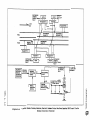
A typical audio frequency overlay ( AFO-IIC) track circuit is shown in Figure
4-6. In this example, audio frequency overlay (AFO-IIC) track circuits are used
for approaches in either a southbound or northbound direction for each track in
the normal direction of traffic. They are designated Sar and NOT (southbound
and northbound overlay track), and each have an assigned frequency with a
separate transmitter and receiver. Island circuits at grade crossing
intersections designated SXOT and NXOT (southbound and northbound crossing
overlay track) utilize an ATT-20 transceiver with an assigned frequency.
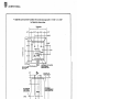
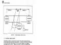
The block diagram shown in Figure 4-6 illustrates circuit interaction for a
typical grade crossing location containing a gate mechanism with gate lights,
flashing mast-100unted signal lights and warning bell. Each block represents a
f1.mctional circuit. The arrow-tipped lines between blocks are transfers of
information from one circuit to another. These transfers are accomplished via
relay contact openings and closures.· The designated relay coils are contained
in the circuit originating the transfer. For example, the Warning Activation
Circuit conditions the status of the Crossing Relay (XR). Contacts of the
normally energized XR relay are then used in the various warning circuits.
Therefore, the warning activation/deactivation sequence is controlled by the
status of the (XR) relay. For example, as long as there is no occupancy of
track circuits in the southbound or northbound approach (SOT and NOT track
relays energized), and no occupancy of island track circuits (SXOT and NXOT
track relays energized), the XR relay is kept in its energized state preventing
warnings from activating.
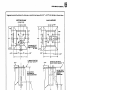
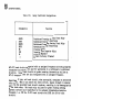
Typical designations and functions of the relays used are given in Table III.
The designations are those found in AAR specifications on signaling. A typical
track circuit diagram with a list of components is shown in Figure 4-7.
4.5.·1
Audio Frequency Overlay (AFO) Train Detection
Each Grade Crossing Warning System location provides the capability to
automatically initiate warning (gate driven to horizontal position, bell and
flashing lights activated) with the presence of a train in one or more of the
location's approach track circuits.
5958, p. 4-7
m
m
UNION SWITCH & SIGNAL
Table III.
Relay Functional Designations
Designation
SXOTR
SOTR
NXOTR
NOTR
XR
SGP
XP
EO
Function
Southbound Crossing Overlay Track Relay
Southbound Overlay Track Relay
Northbound Crossing Overlay Track Relay
Northbound Overlay Track Relay
Crossing Relay
Crossing Gate Repeater Relay
Crossing Repeater
Element On Relay (Flasher)
AFO-IIC track circuits designated with an assigned frequency and having separate
transmitter and receiver are used for approaches in a northbound or southbound
direction. Island track circuits at grade crossing intersections utilize an
ATT-20 transceiver, and are also designated with an assigned frequency.
Regardless of type, each track circuit, when unoccupied, energizes an associated
track relay. When a train enters the track circu:i.t, signal strength is shunted
away from the associated track circuit receiver, resulting in the deenergization
of the track relay. Each track relay utilized for grade crossing warning
approach circuits can be identified by its assigned transmission/reception
frequency, i.e. OTR for AFO-IIC track circuits and XOTR for ATT-20 track
circuits.
4.5.2 Warning Activation
The Warning Activation Circuit provides for automatic or manual activation and
deactivation of grade crossing warnings. When under automatic control,
occupancy of approach and island track circuits determines the status of the
Warning Activation (XR) Relay. When warnings are deactivated (gate in vertical
position, lights and bell off), the XR relay is energized via contacts of
energized approach (OTR) and island track relays (XOTR). Upon occupancy of an
approach track circuit, the XR deenergizes, initiating warnings, and remains
deenergized until the originating approach track circuit and the island track
circuit are unoccupied.
4. 5.~.1
Flashing Warning Li.ghts
Flashing warning lights commence upon deenerg.l.zation of the XR relay, and in
turn, the Crossing Gate Repeater (XGP) Relay. When this occurs, ac power is
applied via contacts of an energized Element On CEO) Relay, (flasher relay) to
alternately flash gate lights, and mast- or cantilever-m::>unted signal lights.
The signal lights continue to flash until the island track circuit has been
passed by the train, and the gate is driven to its deactivated vertical position.
5958, P• 4-8
SOUTHBOUND
CROSSING
OVERLAY TRACK
RELAY
- - - - - , - SOUTHBOUND
SOTR .._ OVERLAY
_____
TRACK RELAY
SXOTR
...__._,-1...
RECEIVER 2
TRANSCEIVER 2
-:: :, , ,.,.Ill
R
T
TRANSMITTER 2
SOUTHBOUND
APPROACH TC
SOUTHBOUND
ISLAND TC
TRACK 2
NORTHBOUND
liLAND TC
NORTHBOUND
APPROACH TC
TRACK 1
TRANSMITTER 1
R
T
ReCEIVER 1
TRANSCEIVER 1
I
I
I
NOR'rHBOUNO
NXOTR
CROSSING
-------""'-'- OVERLAY TRACK
RELAY
NORTHBOUND
NOTR
OVERLAY TRACK
RELAY
....._ _--,11,,,
AFO TRAIN
DETECTION
CIRCUITS
(AUTOMATIC
OPERATION)
I
SOTR.SXOTR
NOTR,NXOTR
WARNING
ACTIVATION
CIRCUIT
I
XR
XR !CONTROL
OF OPTIONAL
.BELLI
...jGATE CONTROL
CIRCUIT
XGP
MANUAL
OPERATION
CONTROL
I
FLASHING
LIGHT SIGNAL
WARNING CIRCUIT
XP (CONTROL
OF GATE ARM
MOVEMENTI
EO (CONTROL OF MAST·
OR CANTILEVi;R AND/OR
GATE ARM LIGHTS)
c
z
0
z
V1
.~
0)
i
~:z:
'CJ
II
.s;:
"'a2
~
Figure 4-6.
Typical Grade Crossing warning Control Scheme Usinq Non-overlapping APO Track Circuits
(Normal Direction Running)
)lo
,-
EB
UNION SWITCH & SIGNAL
4.5.2.2
Gate Activation
Deenergization of the XR, and in turn, the Crossing Repeater (XP) Relay causes
the internal gate mechanism circuits to drive the gate to a horizontal
position. Deactivation (XR relay reenergizes) initiates gate drive up to the
vertical 90 degree position once the island track circuit has been passed by the
train.
4.5.2.3
Warning Bell
Deenergization of the XR causes the crossing warning bell to activate. Bell
shutoff is controlled by the movement of the gate arm during drive down via an
adjustable cam controlled contact of the gate mechanism's circuit controller.
4.5.3
Warning Activation by Manual Operation Control
Each grade crossing location can contain a provision in the control circuits to
effect activation without occupancy of approach or island track circuits. A
normally closed pushbutton circuit in series with the coil energizing path to
the XR relay can be utilized for this f\mction (as shown in Figure 4-6).
4.5.4
Optional Control and Ti.ming Applications
When required, control circuits can be modified to satisfy design criteria
within a grade crossing subsystem or system. The following paragraphs describe
some of these applications.
4.5.4.1
Signaling System Tie-In
Track circuits ordinarily used f-0r train detection within interlocking and/or
automatic block signaling subsystems can be used in conjmction with grade
crossing warning track circuits, and provide an additional means of initiating
warning activation and/or deactivation. Line control circuits between crossing
locations containing contacts of grade crossing and signaling system track
relays can provide varying warning times ( elapsed time between warning
activation and occupancy of the island track circuit), and protection against
AFO (or simil.ar type) track circ u1 t failure. In the event of warning activation
upon grade crossing warning track relay failure, timing circuits can be
configured to deact::t vate warnings after a predetermined time delay to allow the
gate to rise and flashing signal lights to go dark and avoid unnecessary
vehicular or pedestrian traffic buildup.
4.5.4.2
Reverse Traffic Direction Warning Activation
Circuits can also be configured to accommodate reverse as well as normal traffic
direction approaches to a grade crossing warning location. If this were the
case, warning activation woul.d comence upon occupancy of the approach track
circuit for a normal direction running track, and upon occupancy of the island
track circuit (sl.owed or stopped train) or an additional approach track circuit
for a reverse direction rmning track. Warning deactivation would canmence upon
vacancy of the island track circuit for either direction of traffic.
5958., p. 4-1 O
UNION SWITCH & SIGNAL
SECTION V
MAINTENANCE
5.1
GENERAL
The maintenance procedure provided in this manual are limited to field
maintenance. Maintenance procedures beyond the scope of this manual, and shop
maintenance, are covered in the applicable equipment manuals. Procedures
covered in this section include preventive maintenance, ·traibleshooting, and
corrective maintenance.
5.2
PREVENTIVE MAINTENANCE
Preventive maintenance consists of routine cleaning, inspection, and operational
tests. Proper preventive maintenance will help to assure continued
uninterrupted operation of the Grade Crossing Warning System. The procedures
and intervals are those recoimD.ended by Union Switch & Signal. Actual procedures
and intervals depend on the customers own operation and past experience.
Table IV lists the maintenance actions to be performed and recoimD.ended
frequency. Ideally, perform all procedures that are due at the same time.
example, if cleaning and inspection fall at six month intervals, these
procedures should be performed together.
5.2.1
For
Cleaning
Cleaning consists of the removal of dust and dirt from the control equipment
(located in the instrument case), dirt and grime from the flashing light units,
and internal cleaning of the gate mechanism.
5.2.1.1
a.
b.
c.
d.
e.
Equipnent/Materials Required
Lint-free cloths
Soft bristle brush
Can pressed air in aerosol can
Cleaning sol vent
Canmercial cleaning detergent
5.2.1.2 General Cleaning Procedures
WARNING
HAZARDOUS VOLTAGES AND CURRENT MAY BE PRESENT. EXERCISE
EXTREME CARE WHEN WORKING AROUND EXPOSED TERMINALS.
NEVER USE WET CLOTHES NEAR EXPOSED ELECTRICAL TERMINALS.
a.
Remove dust and dirt from the surface of the canponents m:>unted in the
equipnent case and inside the gate mechanism housing with a soft
bristle brush. Blow out dust and dirt from hard to reach areas with·
compressed air in aerosol can.
5958, p. 5-1
m
w
UNION SWITCH & SIGNAL
Table IV.
Maintenance Action
Frequency
Action
Every 30 days
Perform a systems operation test per
paragraph 5.3.
Every 6 months
Clean and inspect all grade crossing
equipment per paragraphs 5.2.1 and 5.2.2.
Lubricate gate mechanism per pa~agraph
5.2.3.
Every 12 months
Vital flasher relays performance test per
applicable service manual.
.Every 24 months
All vital track and control relays
performance test per applicable service
manuals.
b. Remove accumulation of heavy dirt and grime with a lint-free cloth
dampened in a detergent solution. Dry with clean cloth.
c. With a cloth dampened in an approved solvent, wipe clean the gate
mechanism circuit control, motor control relay contacts, and hold clear
amature of any oil, and dirt that may have accumulated during
operational service.
d. Flashing Light Uni ts
1) Clean glass roundels and glass reflectors with a clean cloth
noistened with a detergent solution. Wipe dry.
solvent for hard to remove dirt or grease.
Ose an approved
2) Clean plastic roundels by flushing with clean water, using a cham::,is
or soft cloth.
Ose a detergent for hard to remove dirt.
CAUTION
Do not use any solvents on plastic roundels.
3) Remove dirt from hoods and background with a damp cloth moistened in
a detergent soluticn.
5.2.2
Inspection
Inspect the equipment for damaged parts, etc. in accordance with the foi~owing
paragraphs. Any parts found to be damaged during inspection should immediatel.y
be repaired or replaced. Refer to Section VII, Corrective Maintenance.
5958, p. 5-2
UNION SWITCH & SIGNAL
5.2.2.1
m
Grade Crossing EquiEJilent
a. Broken or cracked light unit roundel and/or reflector.
b. Broken light unit case, door, or other parts.
Damaged lamp receptacle.
c. Faulty or damaged door gasket which would result in water leaking into
the case.
d. Burned out or broken light unit or gate arm lamps.
e. Broken or cracked lens on gate arm lights.
f. Broken or cracked gate arms.
g. Damaged mast and/or signs, or other equipnent.
h. Exterior damage to gate mechanism signs of vanadalism.
i. Interior of gate mechanism for the following:
1) All wiring connections are tight; wiring is free from cuts, nicks,
and fraying.
2) Damage to gears, motor, cams and contacts.
3) Secure mounting of components.
4) Contacts for proper opening (refer to SM6043).
5) Slide contacts on resistors are clean and are bearing on the resistor
windings with firm pressure.
should be tight.
5~2.2.2
Loclcscrew securing the slide contact
Control Equipment
a. Check control case exterior for any signs of physical dam.age or of
vandalism (such as bullet holes). Check for water leaks inside the case.
b. Check batteries for fluid and specific gravity.
assure proper voltage and battery charging.
Ranove all corrosion to
c. Check for loose or damaged electrical connections.
d. Check for loose or damaged components.
e. Check for wiring for burned, frayed, or damaged insulation.
f. Check track circuit cabling for secure connections to track and damage
such as kinks, cuts, etc.
g. Check for insulated joints (if applicable) for damage or deterioration.
5958, p. 5-3
UNION SWITCH & SIGNAL
h. Check relays for:
1)
Cracked or broken cover; broken seals.
2) Pitted or damaged contacts; contact misalignment.
3) Corrosion or other contamination of relay canponents; loose parts
inside cover.
5.2.3 Lubrication
The only equipnent requiring lubrication is the gate mechanism. Every six
months, or more frequently depending on operating conditions, apply a light
brush coat of lubricant to the gear teeth and circuit controller cam. Te:xa.co
Regal Starfax #2 (MIL-G-3278) VA4830 grease, or equivalent is recommended. The
mechanism gear shaft and main shaft bearings are pre-lubricated and double
sealed at the factory and requires no lubrication in the field.
5. 3
SYSTEM OPERATIONAL TEST
NOTE
More frequent operating tests should be made in areas
where the system is seldom or only periodically used.
Where the system is in use daily, a visual observation of
the system should suffice until normal periodic testing.
Keep test records for handy referral so that proper
checks are made at regular intervals.
Every 30 days perform the operational test covered in paragraph 3.8.2. Observe
the operation for any signs of malfunctioning or faulty operation. Initiate
corrective action if any faults are observed.
5.4
5.4.1
TROUBLESHOOTING
Table V covers the more common problems encountered in system
operation. Faulty operation generally will occur in three major areas:
1)
Train detection circuits,
2)
Activation control circuits, and
3)
Gate mechanism.
5958, P• 5-4
UNION SWITCH & SIGNAL
Table V.
Problem
1. Erratic or malfunc-
tioning gate arm
operation; warning
systan operating
properly.
2. Gate arm. remains
Troubleshooting
Cause
Improper gate mechanism
adjustments.
Refer to gate
mechanism SM6043.
Open motor-up circuit.
Ref er to gate
mechanism SM6043.
Loss of primary ac and de
power (common source)
Check distribution
of primary ac power
to signal lighting
transformer and de
rectifier. Check
transformer and
rectifier.
Open gate fuse
Check fuse for
continuity. If
required, replace
with identical fuse.
Loss of de power
Check distribution
of de power to control relays.
Check power supply i
or rectifier.
;
Malfunctioning flashing
signal lighting circuit.
Check operation of
flashing signal.
lighting circuit
(specifically, the
flasher relay and
distribution of ac
to signal lighting
lamps).
Malfunctioning flashing
signal lighting circuit.
Check operation of
flashing signal.
lighting circuit
(specifically, the
flasher relay).
Check lamps •
down when track
is unoccupied.
3. Gate in horizontal
position with other
warnings not activated.
4. Gate in horizontal
position with steady
lit gate and signal
lights.
5. Control system
activated; gate and
signal lights malfunctioning (not
flashing, one side
not lit, etc.)
Remedy
5958, p. 5-5
m
m
UNION SWITCH & SIGNAL
Table
Prob.Lem
6. Activation of warnings
with no occupancy;
flashing lights on
gate down.
7. System remains activated after train
leaves control areas;
flasning lights en,
gate remains down.
a.
Gate goes up; flashing
lights remain on with
no occupancy.
9. Flashing lights go
dark; gate remains
down with no occupancy.
5958 I P• 5-6
v.
Troubleshooting (Cont'd.}
Cause
Remedy
Train detection equipment
failure (one or more track
relays deenergize resulting
in warning control relay
deenergizing).
Refer to applicab.1.e
train detection
manual • Check relays •
Open in energizing path
to warning control relay
resulting in deener giza tion.
Check continuity of
energizing path to
warning control relay.
Open in manual
activation circuit.
Check operation of
manual activation
circuit.
Malfunction relay in
activation circuit.
Check relays.
Malfunctioning detection
equipment.
Troubleshoot detection
circuit/equipment and
correct. Check
relays. Rep.lace if
faulty.
Malfunctioning activation
equipment.
Troubleshoot activation circuits/equipment and correct.
Check relays. Rep.lace
if faulty.
Malfunctioning .1.1.ghting
control circuits.
Troubleshoot control circuit/equipment and correct.
Check re.Lays. Replace
if fau.lty.
Malfunctioning gate
contro.1. circuit.
Troubleshoot control circuit/equipment and correct.
Check relays.
Replace if faulty.
UNION SWITCH & SiGNAL
5.5
CORRECTIVE MAINTENANCE
Corrective maintenance consists of repairing or replacing damaged or faulty
components or equipment. In general, most items can be replaced in the field to
restore the system to full operation. This would include control equipment such
as relays, rectifiers, transformers, and detection equipment. Minor repairs can
also be done in the field such as replacing roundels, lamps, damaged signs,
broken gate arms, etc. Items requiring major repair should be returned to the
shop such as:
a.
Gate mechanism for damage to gears, contacts, cams, motor,
clutch, etc.
b.
Relays for broken covers, damaged or misaligned contacts.
c.
Light units for broken reflector, lamp receptacle, case and
case door.
d.
Train detection unit if it does not meet minimum performance
standards and cannot be brought into specification through
normal adjustments.
5958, P• 5-7/5-8
m
UNION SWITCH & SIGNAL
SECTION VI
REPLACEMENT PARTS
6.1
GENERAL
For detail parts of the major components, refer to the applicable service ~nual.
listed in Table I. For parts and equipment associated with a specific
installation, refer to the applicable drawings (see Figure 4-7 for an example).
Miscellaneous parts information for signs, bases, etc. are covered in the
following catalog sections included in this section:
RSE-10B1
RSE-10B2
RSE-10B3
Grade Crossing Masts
Jmiction Box Bases
Grade Crossing Signs
6.2 REPLACEMENT LAMPS
For convenience, replacement lamps for the flashing light units and the gate arm.
lights are listed below:
a.
Flashing Light Units and Gate Arm Lights
10 Volt - 18W
10 Volt - 25W
110 Volt - 25W
a.
S.C.B.C. Base
S.C .B.C. Base
s.c.B.C. Base
J071463
J071574
J714054
Flashing Light Uni ts Only
10 Volt
10 Volt
- 16W
- 36W
Quartz Iodide
Quartz Iodide
J714283
J714284
5958, P• 6-1/6-2
m
....------------------------------------------------------------------------------------
GRADE CROSSING MASTS
US & S masts axe constructed of aluminum for easy handling, long life, and minimum maintenance. The
13' 6" mast is used for mounting grade crossing signals, signals with gate assemblies, or gate assemblies,
only. A 6' 9" stub mast is available for mounting US & S's gate rnechansim with gate arm. The 15' 3" mast
is designed for converging highway applications. An additional hole is drilled at appropriate angle from
the center to accommodate additional crossarms.
CONVERGING
ANGLE 150°
4AND 5-INCH
GRADE CROSSING ALUMINUM SIGNAL MASTS
\
(FOR USE WITH 17" HIGH JUNCTION BOX BASES
WITH 1M1/16"BOLTSPACING}
'
90°--Q
/•
PART NO.
MAST
DIA.
ORDERING INFORMATION
J.B.
J.B. BASE
CROSSARM
MAST
HOLE
HOLE
HEIGHT
M451394-4301
M451394-4201
4"
5"
6'9"
6'9"
M451394·4401
M451394-3902
4"
5"
13'6"
13'6"
M451394-4101
M451394·4001
M451394-4102
M451394·4002
M451394·4103
M451394-4003
M451394-4104
M451394-4004
4"
5"
4"
5"
4"
5"
4"
5"
15'3"
15'3"
15'3"
15'3"
15'3"
15'3"
15'3"
15'3"
oo
00
oo
ao
ao
oo
00
oo
oo
00
ao
oo
30°
CONVERGING
CROSSARM
HOLE
·-
-
ao
ao
-
-
00
NOTES
-
-
-
oo
oo
ao
ao
30°
30°
00
goo
oo
oo
~o
goo
150°
150°
4-INCH
GRADE CROSSING ALUMINUM SIGNAL MASTS
{FOR USE WITH 12" HIGH JUNCTION BOX BASE
WITH 9· 1/2" SOLT SPACING}
PART NO.
M451394-5101
M451394·5102
. .~.•
~
..... ,.,.
MAST
DIA.
4"
4"
ORDERING INFORMATION
J.B.
MAST
J.B. BASE
CROSSARM
HEIGHT
HOLE
HOLE
13'6"
15'3"
ao
ao
oo
oo
CONVERGING
CROSSARM
HOLE
.
NOTES
-
900
UNION SWITCH & SIGNAL DIVISION
AMERICAN STANDARD INC. I SWISSVALE, PA 15218
RSE-1081
sng
m
UNION SWITCH & SIGNAL
PINNACLE ANO APPLICATION HARDWARE
REF.
A
A1
B
81
c
RSE-lOBl
p.2
PART NO.
ORDERING INFORMATION
DESCRIPTION
J026104
J026111
M451195-3601
M451195-3602
N199590
PINNACLE for 4" diameter mast
PINNACLE for 5" diameter mast
RODENT COVER PLATE for4" diameter mast
RODENT COVER PLATE for 5" diameter mast
STEP, GALVANIZED, includes mounting hardware
NOTES
JUNCTION BOX BASES
FOR 4-AND 5-INCH MASTS
U S & S junction box bases are constructed of aluminum for easy handling, long life, and minimum maintenance. They provide for terminating leads at the mast base. These junction box bases facilitate installation
and maintenance.
a m1·
.
!. 9-1/2" I
~---l
9-1 /2"
A
fn{l:'JI
!>"!",.,.,..
--~
Il 1IIl
I.
9-1 /2"
,I
1.
9-1/2"
!
I
~
I,
a:
ID
I
i
-·c
I
.1
~
11-11/16"
I
~\
,I
.-
-
••
.
T
17"
J
11-11/16"
C/C1
17"
IL
11
J_
µ
I
I
11-11/16"
~
C2
I
8
REF.
PART NO.
MAST
DIA,
FON. BOLT
SPACING
BASE
HEIGHT
NO.
TERM.
NOTES
A
J705049-0201
4"
9-1/2 "
12"
12
Not For Use With Gates
B
J705049-0203
4"
9-1/2"
12"
None
·Plain Clamp Base
c
J705049-0602
J705049-0801
J705049-0901
4"
5"
5"
17"
17"
17"
24
24
48
C1
C2
11·11/16"
11·11/16"
11-11/16"
For FOUNDATION BOLTS see RSE-10F1.
UNION SWITCH & SIGNAL DIVISION
RSE -1082
AMERICAN STANDARD INC. I SWISSVALE, PA 15218
REV. 8/80
GRADE CROSSING SIGNS
U S & S grade crossing warning signs are made of
aluminum and include all hardware necessary for
mounting. Signs can be ordered in engineering
grade Scotch-Lite®or Hi-Intensity reflex-reflection.
U S & S signs conform to AAR requirements.
"RAILROAD CROSSING" SIGN
All aluminum construction with black lettering
anc:t includes mounting hardware.
STANDARD
PART NO.
X392931-001
X392931·007
X392931-002
X392931 ·008
X392931·005
X392931·009
X451506-0711
X451506-0712
MAST SIZE
BACK ROUND
1O" (Pipe Mast)
10" (Pipe Mast)
10/11" (Tapered Mast)
10/11" (Tapered Mast)
Engineering Grade
Hi-Intensity
Engineering Grade
Hi-Intensity
Engineering Grade
Hi-Intensity
Engineering Grade
Hi-Intensity
4"
4"
5"
5"
WITH STAND-OFF for Wooden Gmte Arms
PART NO.
MAST SIZE
X438002·002
X438002·003
4"/5"
4"/5"
UNION SWITCH & SIGNAL DIVISION
AMERICAN STANDARD INC. I SWISSVALE, PA 15218
BACKGROUND
Engineering Grade
Hi-Intensity
RSE-1083
sng
ffi
UNION SWITCH & SIGNAL
"TRACKS" SIGN
Specify number required. All aluminum construction with black lettering and includes mounting hardware.
STANDARD
rrlfu
PART NO.
MAST SIZE
BACKGROUND
X392929-001
X392929-005
X392929-002
X392929-00.
X392929·004
X392929-007
X451506·0714
X451506-0715
4"
4"
5"
S."
10" (Pipe Mast)
10" (Pipe Mast)
10/11" (Tapered Mast)
10/11" (Tapered Mast)
Engineering Grade
Hi-Intensity
Engineering Grade
M.-!ntensity
Engineering Grade
Hi-Intensity
Engineering Grade
Hi· Intensity
WITH STAND-OFF for Wooden Gate Arms
I
I
I
I
I
I
.
I
.,. .
-
BACKGROUND
MAST SIZE
PART NO.
I
I
Engineering Grade
Hi-Intensity
4 "/5"
4" /5"
X437997
X437997·001
t
I
"STOP ON RED SIGNAL" SIGN
All aluminum construction with black background. Includes mounting hardware.
STANDARD
PART NO.
MAST SI E
L
'5 TO p'
ON RED
I
SIGNAL
I
X392930-001
X392930-005
X392930-002
X392930-006
X392930-004
X392930-007
X451506-0720
X451506-0721
4"
4"
5"
5"
1O" (Pipe Mast)
1O" (Pipe Mast)
10/11" (Tapered Mast)
10/11" (Tapered Mast)
Engineering Grade
Hi- I ntensitv
Engineering Grade
Hi-Intensity
Engineering Grade
Hi-Intensity
Engineering Grade
Hi-Intensity
WITH STAND-OFF for Wooden Gate Arms
PART NO.
I
I
I
X438077
X438007·001
MAST SIZE
LETTERING
4"/5"
Engineering Grade
Hi-Intensity
4" /5"
STAND-OFF BRACKETS { Includes hardware. )
RSE-10B3
p.2
4"/5" MAST
PART NO.
SIGN
N438004-001
N437999
N438078
"Railroad Crossing"
"Tracks"
"Stop On Red Signal"
10"/11" MAST
PART NO.
SIGN
X451506-0710
X451506-0713
X451506·0719
"Railroad Crossing"
''Tracks"
"Stop On Red Signal"