1
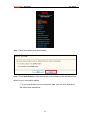
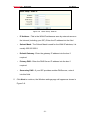
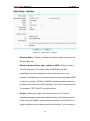
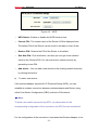
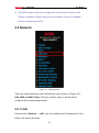
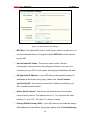
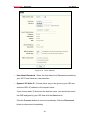
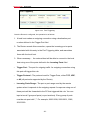
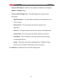
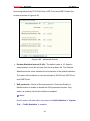
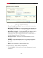
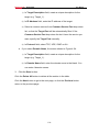
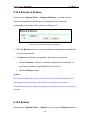
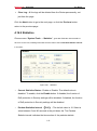
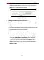
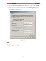
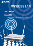
Wireless Router RNX-N360RT User Manual Figure 4-16 Wireless Settings SSID - Enter a value of up to 32 characters. The same name of SSID (Service Set Identification) must be assigned to all wireless devices in your network. Considering your wireless network security, the default SSID is set to be Rosewill_XXXXXX (XXXXXX indicates the last unique six numbers of each Router’s MAC address). This value is case-sensitive. For example, TEST is NOT the same as test. Region - Select your region from the pull-down list. This field specifies the region where the wireless function of the Router can be used. It may be illegal to use the wireless function of the Router in a region other than one of those specified in this field. If your country or region is not listed, please contact your local government agency for assistance. -65-