1
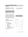
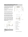
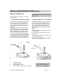
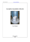
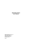
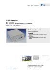
Drying Cabinet Installation and Operating Manual Models:ETS-1900H ETS-1900TR CONTENTS ABOUT THE USER MANUAL Page 2 IDENTIFICATION DATA PLATE Page 2 IMPORTANT SAFETY INSTRUCTIONS Page 3 INSTALLATION INSTRUCTIONS Page 4 OPERATING INSTRUCTIONS Page 8 CARE AND MAINTENANCE INSTRUCTIONS Page 10 TROUBLE SHOOTING Page 10 SERVICE UNIT Page 10 TECHNICAL DATA Page 11 ABOUT THE OPERATING MANUAL This manual describes the cabinets functions and operation and includes instructions for installation and maintenance. PEKO Equipment Limited reserve the right to make improvements and/or changes to the cabinet and to the contents of this manual: Origination: 01/2008 Revised 02/09: UK version Revised 07/09: v2, Dimensions Revised 07/13: v3, Vent spigot Peko Equipment Limited Peko House Northbridge Road Berkhamsted Herts. HP4 1GE tel: 01442 872323 fax: 01442 866900 www.peko.co.uk DATA PLATE DETAILS Your Reference Date of purchase: _______________ Serial number: Located inside the cabinet on the left hand side panel Page 2 _______________ Installation and Operating Manual IMPORTANT SAFETY INSTRUCTIONS IMPORTANT These instructions and warnings have been provided to help avoid misuse and unnecessary risks and should be read before the cabinet is installed and used. NOTE: Keep this manual in a safe place so that it is always available for future use. WARNING To reduce the risk of fire, electric shock, or injury to the person when using the appliance, follow basic precautions including the following: Read all the instructions before using the appliance. Do not dry articles that have been previously cleaned in, washed, soaked or splashed with petrol or other flammable or explosive substances as they give off vapours that could ignite or explode. Check the exhaust ducting terminal grille for any blockages or build-up of lint, and clean regularly. The interior of the appliance and the exhaust duct should be cleaned periodically by a competent person. The manufacturer accepts no liability for repairs carried out:a) by unauthorised personnel. Do not allow children to play on or in the appliance. Close supervision of children is required whilst the cabinet is in operation. b) use of non-standard parts. Do not install or store this appliance where it will be exposed to the weather. WARNING LABELS Do not tamper with the controls. Do not repair or replace any part of the cabinet or attempt any servicing unless specifically referred to in this manual. Do not use fabric softeners or products designed to eliminate static unless recommended by the manufacturer. Do not use heat to dry articles containing foam rubber or similar textured rubberised materials. To dry this type of material use the cabinet with only the fan operating. Affixed to rear inside panel Keep area around the exhaust opening and adjacent areas free from the accumulation of dust, lint and fluff. Underside of heater cartridge Installation and Operating Manual Page 3 INSTALLATION INSTRUCTIONS UNPACKING WARNING: The cabinet should be handled and transported with care. The unit is top heavy with the risk of tipping over when positioned on its wooden pallet. Remove all packaging material. Do not use sharp implements which could damage the cabinet. Check that the goods have not been damaged in transit. Any damage should be recorded on the delivery note and reported to your dealer within 3 days. After unpacking, check that the cabinet is in good condition. Any damage or shortages should be immediately reported to the supplier. Occasionally the door sealing gasket may be compressed by the packaging material and a gap will be visible. This will not impair the overall performance of the cabinet. Once the cabinet is in operational use and heat is applied, the gasket should restore itself to seal Check that all restraining tape and protective polystyrene buffers are removed from inside the cabinet. CONTENTS The drying cabinet is supplied complete together with a user manual and fixing kit. Fixing kit. Ref. Description Qty. 1 Ventilation adaptor 1 2 Flexible hose approx 1m. 1 3 Spigot adaptor to cabinet 1 4 Screw, Torx 5 x 70 2 5 Washer, 5 x 25 2 6 Wallplug 2 7 Nylon spacer 8.2 x 12 x 15 2 8 Cover plug, white 4 9 Levelling toolbar 1 10 Screw to fix spigot, Torx 3 x 10 2 11 Pull handle incl.4 Torx fixing screws Items 10 and 11 are not shown on the assembly kit diagram. Page 4 Installation and Operating Manual INSTALLATION INSTRUCTIONS (cont.) REVERSING THE DOOR HINGE SIDE The door can be changed to open from the left or right hand side. 1. 2. 3. 4. 5. Use the packaging material on the floor to protect the cabinet, then place down with the door uppermost. Remove the pivot pin from the lower hinge (1) and lift off the door. Remove the lower plastic guide plug on the unused hinge bracket and refit to the opposite side. Unscrew the pivot pin from the upper hinge (2) and fix to the opposite side. Turn the door upside down and locate into the upper hinge pin; position door on lower hinge bracket and plastic guide, then screw in the lower hinge pin with the washer between the door and bracket. Installation and Operating Manual Page 5 INSTALLATION INSTRUCTIONS (cont.) LOCATING AND FIXING THE CABINET The appliance should not be located in a position such that any doorways or safety exits are impeded with the cabinet door open and the hanging rails extended. The drying cabinet is only designed for operation indoors in a dry environment at a temperature above 0oC. The unit should not be installed in areas where high pressure water cleaning is carried out. The cabinet should stand level on a flat surface. Adjust using the toolbar through the access holes in the base panel of the unit. Ensure that the top edges of the doors are level. The cabinet must be screwed to the wall to prevent it tipping forward when the doors are opened. There are two holes in the rear panel of the unit for securing the dryer to the wall. Open the door and drill two 8mm holes through the rear panel into the wall avoiding any hidden water pipes or cables etc. Insert the wall plugs and with the spacers and washers supplied, screw the cabinet back to the wall. Fit the 4 plastic plugs to the base of the cabinet. Fix the pull handle to the side of the door with the 3 white headed screws. WARNING The cabinet should not be used without being fixed to the wall. Page 6 1 Pre-drilled hole 2 Fixing screw with washer 3 Plastic wall plug 4 Wall construction 5 Nylon spacer 6 Back panel of cabinet 7 Spirit level 8 Levelling toolbar 9 White plastic plugs Installation and Operating Manual INSTALLATION INSTRUCTIONS (cont.) EXHAUST CONNECTION The cabinet can be connected to an exhaust duct in two ways: The exhaust ducting should not be connected into an existing chimney, boiler flue or tumble dryer system. 1. CONNECTION TO AN EXISTING SYSTEM 2. DIRECT CONNECTION TO OUTSIDE WALL This method is only suitable for buildings that have an existing mechanical ventilation system, or where the room has a dedicated extraction fan with a capacity of 54 m3 / hour. In both cases the ducting must terminate on an outside wall. Fit the spigot to the top of the cabinet using the 2 small Torx screws. Fit the white plastic ventilation adaptor over the existing wall or ceiling mounted grille (fixing screws for this ‘tripod’ type fitting are not supplied), and then connect to the cabinet using the flexible hose. Note: The exhaust ducting fittings supplied are a standard 100mm diameter, and any additional hose or fittings required are available from most builders merchants and hardware stores. Fit the plastic spigot under the three lugs on top of the cabinet. Core cut a 100mm. diameter hole in the outside wall, or alternatively cut a hole in a fixed pane of window glass. Fit an appropriate terminal grille with a fixed open louvre, preferable one with an integral insect mesh screen. Notes: Standard tumble dryer back draught shutters are not suitable. The maximum effective length of ducting to outside is 3m. Rigid metal and plastic pipe can also be used for the exhaust ducting. Ensure that the ducting and terminal grille are cleaned on an annual basis. 1 2 3 4 Ventilation adaptor Flexible plastic hose Spigot adaptor to cabinet Hose coupler to extend ducting; not supplied Installation and Operating Manual The air intake grille must not be covered. Do not use the top of the cabinet as a storage shelf. Page 7 INSTALLATION INSTRUCTIONS (cont.) ELECTRICAL CONNECTIONS The cabinet is supplied ready for connection to the power supply with a UK style three pin plug complete with a 10 A fuse. The power supply rated at 220- 230volt, 50-60 Hz. The power cable is approx. 2.2m in length. The plug (and socket outlet) should be in an accessible position for ease of removal. An alternative arrangement could be a high level fused outlet plate with a separate switch at worktop height. If the plug supplied is not suitable for the socket outlet, or if the appliance is to be connected to fixed wiring, it should be cut from the supply cord and disposed of immediately. If the severed plug is introduced into a live socket outlet WARNING: This appliance must be earthed. there is a risk of electric shock. If in any doubt consult a competent person. OPERATING INSTRUCTIONS GENERAL WARNING To reduce the risk of fire, electric shock, or injury to the person, read the IMPORTANT SAFETY INSTRUCTIONS before operating this appliance. LOADING THE CABINET Model ETS-1900TR The cabinet contains three shelves with hangers. The shelves can be pulled forward to assist loading, then pushed back inside the cabinet before closing the door. The middle and lower sets of rails are hinged and can be lifted to the upright position against the rear panel. This option allows longer garments to hang freely from the top set of rails. Model ETS-1900H Ten double hooks are fitted inside the cabinet for hanging longer garments, boiler suits and heavy outdoor workwear etc. Page 8 Do not lay items flat on the upper hanging rail section. Hang long clothes to the outer walls of the cabinet with shorter items to the centre. Hang gloves, scarves, socks and small items on the hanging bars fixed to the inside door panel. Do not overload the drying cabinet. The washing will become creased and dry unevenly. Leave some space between items, especially through the centre of the cabinet for improved drying efficiency. Separate dark and white loads to avoid transferring colours. Avoid drying thick clothes at the same time as lighter articles as they hold more moisture and will take longer to dry. Delicate and knitted garments should be laid flat on the hanging shelves to avoid creases. Installation and Operating Manual OPERATING INSTRUCTIONS CONTROLS The cabinet is designed with two control switches for ease of use. The left hand switch controls heat settings. The ‘0’ position circulates ambient temperature air only. Rotating the switch position in a clockwise movement increases the heat input up to a maximum 1.5 kW. The right hand switch controls the drying time up to a maximum of 4 hours. SETTING THE CONTROLS Always follow the washing instructions as shown on the care labels. Set the temperature and the time to suit the most delicate articles to be dried. Remove garments from the cabinet as they become dry. This will speed up the drying process for the remaining damp items. AIRFLOW The diagram to the right shows the optimum airflow through the cabinet. Installation and Operating Manual Page 9 CARE CLEANING High pressure water jet cleaning should not used on this cabinet. The use of bleach, caustic solutions and abrasive materials is not recommended. The cabinet should be cleaned (inside and out) using a mild detergent with a damp cloth. Dust will collect on top of the cabinet, especially around the air intake. This may cause problems leading to machine failure and is also a fire risk. To avoid these problems the top of the cabinet should be vacuum cleaned at least once a year or more frequently depending on the location of the unit and it’s application. TROUBLESHOOTING PROBLEM The fan does not run and no heat. Check that the cabinet is connected to the power supply and that the fuse has not blown. The drying cabinet is not heating although the temperature selector is correctly set and the circulation fan is running. The over heat thermostat may have tripped out. Turn the timer selector knob back to zero, wait for 30 minutes then restart with both time and temperature knobs in operational zones. In the event of further problems please contact your dealer. SERVICE MODULE The service module can be removed from the cabinet to enable any repairs or maintenance work to be carried out. WARNING Isolate the electrical supply and remove the plug and power cord before withdrawing the service control unit. Page 10 Installation and Operating Manual SERVICE (CONT.) NOTE: Replacement power cords should only be fitted by a qualified electrician. REPLACING THE POWER CORD If the power cable is damaged in any way, it must be replaced. Replacements are available from your main supplier or dealer. NOTE: Should the plug need to be replaced for any reason, the wires in the mains lead are coloured in accordance with the following code: Green and Yellow: Earth Blue: Neutral Brown: Live The wire coloured green and yellow must be connected to the terminal marked with the letter ‘E’ or by the earth symbol =,or coloured green and yellow. The wire coloured blue must be connected to the terminal ’N’ or coloured black. The wire coloured brown must be connected to the terminal marked ‘L’ or coloured red. If the fuse incorporated in the plug needs to changed then it should be replaced with a fuse approved by ASTA to BS1362, rated at 10 A. TECHNICAL DATA Capacity: Evaporation rate: Electrical supply: Motor: Heating element: Overheat cut-out: Timer: Fan capacity: Sound level: Dimensions: Weight: Colour: 5kg (approx. wet weight) MANUFACTURING general laundry textiles. APPROVALS 17 g/min. Protection class IP 24 220-230v, 50-60Hz, a.c. 35W. (See data plate for details) 1500W. Yes. 0 - 4 Hours. 180 m3/h 60 dB(A) maximum Height. 1900mm. (+ 15mm. level adjustment) Depth. 620mm. (630mm. overall pull handle) Width. 595mm. 57kg. White. PERFORMANCE SPECIFICATION AND ENERGY CONSUMPTION* (Based on general household laundry processed in a washing machine with high spin extraction) SETTING POWER CONSUMPTION DRYING TIME TEMPERATURE Economy 0.5 kW /kg laundry Approx. 180 min. 30 - 50 deg.C Fast 0.6 kW /kg laundry Approx. 120 min. 50 - 70 deg.C *Values quoted above are approximations and will vary with type of load and ambient conditions Installation and Operating Manual Page 11 EQUIPMENT LIMITED Peko House Northbridge Road Berkhamsted Herts. HP4 1GE Tel: 01442 872323 Fax: 01442 866900 www.peko.co.uk