1
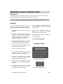
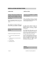
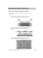
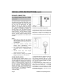
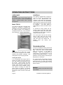
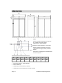
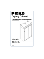
Drying Cabinet Installation and Operating Manual Model:TS-5121 Orig. 10/13 CONTENTS ABOUT THE OPERATING MANUAL Page 2 IMPORTANT SAFETY INSTRUCTIONS Page 3 INSTALLATION INSTRUCTIONS Page 4 OPERATING INSTRUCTIONS Page 8 MAINTENANCE INSTRUCTION Page 9 TECHNICAL DATA Page 9 DIMENSIONS Page 10 ABOUT THE OPERATING MANUAL This manual describes the cabinets functions and operation and includes instructions for installation and maintenance. In addition to this Operating Manual there is a Service Manual and Spare Parts List. The Service Manual is intended for use by personnel trained to service this product. Orig. 03/13 V2 10/13 Peko Equipment Limited Peko House Northbridge Road Berkhamsted Herts. HP4 1GE tel: 01442 872323 fax: 01442 866900 www.peko.co.uk PEKO Equipment Limited reserve the right to make improvements and/or changes to the cabinet and to the contents of this manual: Dimensions DATA PLATE DETAILS Your Reference Date of purchase: _______________ Serial number: Located inside the cabinet on the left hand side panel Page 2 _______________ Installation and Operating Manual IMPORTANT SAFETY INSTRUCTIONS IMPORTANT These instructions and warnings have been provided to help avoid misuse and unnecessary risks and should be read before the cabinet is installed and used. NOTE: Keep this manual in a safe place so that it is always available for future use. WARNING To reduce the risk of fire, electric shock, or injury to the person when using the appliance, follow basic precautions including the following: Read all the instructions before using the appliance. Do not dry articles that have been previously cleaned in, washed, soaked or splashed with petrol or other flammable or explosive substances as they give off vapours that could ignite or explode. Check the exhaust ducting terminal grille for any blockages or build-up of lint, and clean regularly. The interior of the appliance and the exhaust duct should be cleaned periodically by a competent person. The manufacturer accepts no liability for repairs carried out:a) by unauthorised personnel. b) use of non-standard parts. Do not allow children to play on or in the appliance. Close supervision of children is required whilst the cabinet is in operation. WARNING LABELS Do not install or store this appliance where it will be exposed to the weather. Do not tamper with the controls. Do not repair or replace any part of the cabinet or attempt any servicing unless specifically referred to in this manual. Do not use fabric softeners or products designed to eliminate static unless recommended by the manufacturer. Affixed to rear inside panel Do not use heat to dry articles containing foam rubber or similar textured rubberised materials. Keep area around the exhaust opening and adjacent areas free from the accumulation of dust, lint and fluff. Installation and Operating Manual Underside of heater cartridge Page 3 INSTALLATION INSTRUCTIONS UNPACKING INSTALLATION Check for external signs of damage to the packaging. This may indicate that the consignment has suffered damage in transit. Any damage should be immediately recorded on the delivery note and reported to your dealer within 3 days. The dryer is only designed for operation indoors in a dry environment at a temperature above freezing point. Remove all packaging material. Do not use sharp implements which could damage the cabinet. After unpacking, check that the cabinet is in good condition. Any damage or shortages should be immediately reported to the supplier Check that all restraining tape and protective polystyrene buffers are removed from inside the cabinet. Checklist of items supplied with the cabinet 2 x Coach screws, washers and wall plugs. 4 x plastic caps to cover access holes in base of unit.. NOTE: The appliance should not be located in a position such that any doorways or safety exits are impeded with the cabinet door open and the hanging rails extended. The lifting straps adjustable feet can lifting the cabinet damaging the feet, across the floor. positioned around the be used to assist with into place. To avoid do not drag the cabinet The cabinet should stand level on a flat surface. Adjust using the toolbar through the access holes in the base panel of the unit if space around the cabinet is restricted. Ensure that the top edges of the doors are level. The cabinet must be fixed to the wall to prevent it tipping forward when the doors are opened. Two adjustable brackets are supplied and these are bolted to the top panel. They allow for off-setting the cabinet to avoid obstructions behind e.g. skirting boards, service pipes, trunking and cables. Levelling toolbar. Operating manual. WARNING The cabinet should not be used without being fixed to the wall. Page 4 Installation and Operating Manual INSTALLATION INSTRUCTIONS (cont.) INSTALLATION WHERE ACCESS SPACE IS LIMITED The upper section of the cabinet can be removed to reduce the overall height by 207mm. 1. Remove two T20 screws from the under edge of the fascia panel located through the square holes, then slide the panel upwards. 2. Loosen the four T20 screws securing the door switch bracket and slide it backwards. Tighten one of the screws to secure in this position . 3. Remove the four T30 screws from the underside of the control module. With assistance, lift the cartridge clear from the cabinet. Installation and Operating Manual Page 5 INSTALLATION INSTRUCTIONS (cont.) EXHAUST CONNECTION The exhaust ducting should not be connected into an existing chimney, boiler flue or tumble dryer system. The dryer must be connected directly to an exhaust ducting system that terminates on the outside of the building. This could be through the roof or on an external wall. The outlet spigot on top of the cabinet is 125mm diameter. The effective length of the ducting ‘A’ is 23m of straight pipe. If the diameter of the pipework is increased to 160mm, the effective length is 70m. The effective length of the system will vary depending on the type of ducting material and the number of bends used. The cabinet operates more efficiently with the minimum length of ducting and the unit should be positioned on an external wall if possible. Commissioning the ducting system To optimise the efficiency of the cabinet the damper situated on top of the unit should be adjusted to a setting that corresponds with the pressure drop in the ducting. The maximum permissible pressure drop is 70pa. Notes: Rigid metal or plastic pipe is preferred although flexible ducting can be used for some installations within close proximity to an outside wall. Wall vented systems, including fixed window pane applications, should terminate with an open louvre grille. Roof vented systems should be fitted with a weather cowl or a downward facing bend. Standard tumble dryer back draught shutters should not be used. Ensure that the ducting and terminal fittings are cleaned on an annual basis. ROOM VENTILATION The cabinet has an exhaust airflow of up to 250 cubic metres per hour. This air has to be sourced initially from within the room where the dryer is installed. It is important to ensure that there is a continuous supply of fresh air into the room. The air intake into the cabinet is via the door surrounds - sealing gaskets are not fitted for this reason. The recommended free area of the air intake into the room must not be less than 142cm2. The resistance caused by grilles or shutters must not exceed: 10 Pa (0.1 mbar). Page 6 If the pressure drop is greater than this, an external fan must be installed. The dryer has electrical terminals inside the control console suitable for connecting an external fan. The fan would then operate only when the cabinet is in use. If several cabinets are installed adjacent to each other it is advisable to fit a separate ducting system to each unit. If a single ducting pipe is to be considered for a multi unit installation, it would be advisable to seek professional advise from a specialist heating and ventilation engineer. Installation and Operating Manual INSTALLATION INSTRUCTIONS (cont.) ELECTRICAL CONNECTIONS U.K. All electrical work should be carried out only by a suitably qualified and competent person, in strict accordance with national and local safety regulations. Ensure that power is not connected to the appliance while installation work is being carried out. The cabinet is supplied as standard in two versions suitable for connection to:- 230 volt single phase: fuse rating 32 amp. All supply cables into the cabinet should be clamped using the glands fitted to the top panel. The top fascia panel should be removed to access the terminal connecting block. Remove The fascia panel can now be removed. Ensure that all panels are refitted before the machine is operated. 400 volt three phase and neutral: fuse rating 3 x 10 amp. NOTE: NOTE: The voltage, total load and fuse rating details can be found on the data plate on the inside of the cabinet. Connecting external devices. A terminal block inside the control console is wired and labelled to accept an external ducting fan and coin/token operated mechanism if required. The cabinet is not supplied with a mains cable. The size and type of cable should be determined by a qualified electrician to suit the power supply and the location of the installation. Connection should be made via a suitable isolator which complies with national and local safety regulations, and the on/off switch should be easily accessible for any servicing work. When switched off there must be an all-pole contact gap of 3mm in the isolation switch (including switch, fuses and relays according to VDE 0660). For additional safety it is advisable to include a residual current devise (RCD) within the installation. WARNING: This appliance must be earthed. If in any doubt consult a competent person. Installation and Operating Manual Page 7 OPERATING INSTRUCTIONS USER GUIDE CONTROLS WARNING To reduce the risk of fire, electric shock, or injury to the person, read the IMPORTANT SAFETY INSTRUCTIONS before operating this appliance. The cabinet is supplied with a simple to use touch pad with two heat settings for ease of use, Whites/colours and Synthetics. Both options are controlled by moisture sensors and will automatically switch the power off when then the laundry has reached the correct level of dryness. An automatic cool down period of approximately 8 minutes is built into each cycle. Model TS-5121 The cabinet is fitted with a stainless steel hanging rail mounted on a spindle. The assembly can be moved outwards to assist the loading process. The assembly is comprised of either four or five horizontal rails at alternate levels as shown below To operate the drying cabinet sort the laundry in cottons or synthetic loads, select the appropriate setting, then press start. The buttons are also written in Braille to assist those with poor sight. The control panel also has two warning lamps to alert users that the lint filter requires cleaning requires cleaning. The right hand lamp will indicate that a problem exists with heating when illuminated. TROUBLESHOOTING Option The cabinet can be fitted with a single stainless steel hanging rail (not shown) instead of the standard assembly. This arrangement may suit longer garments. Loading the cabinet It is recommended that longer items of laundry are located to the top section of rails with shorter items towards the lower set of rails. Shoes, trainers and other items can be placed in the base of the unit. Laundry items should be spread evenly over the rails to ensure consistent drying. This method of loading will assist the drying process by allowing the efficient flow of warm air through the cabinet. Do not block the warm air ducts on the inside panels. Page 8 In case of overheating the drying process will stop and three lamps on the control panel will flash. Check and clean the filter located inside the top panel of the cabinet if necessary. When the temperature has cooled down to its operating level, only the overheat warning lamp will flash. It is now possible to re-set by pushing and holding the Stop button for 10 seconds. The cabinet will stop automatically if the filter is blocked and the Clean Filter warning symbol will flash. To remedy, clean the filter and re-set by pressing and holding the stop button as above WARNING: Do not place laundry or any other items on top of the cabinet. Installation and Operating Manual MAINTENANCE INSTRUCTIONS CLEANING High pressure water jet cleaning should not used on this cabinet. The use of bleach, caustic solutions and abrasive materials is not recommended. The cabinet should be cleaned (inside and out) with a damp cloth using a mild detergent solution. Dust will collect on top of the cabinet therefore it should be cleaned at least once a year or more frequently depending on the location of the unit and it’s application. A lint filter, situated inside the cabinet and above the hanging rail assembly, should be periodically removed and cleaned with a soft brush. TECHNICAL DATA Capacity: Evaporation rate: Electrical supply: Motor: Heating element: Overheat cut-out: Timer: Dimensions: (Overall) Net Weight: Colour: 8kg (approx. weight) general laundry textiles. 81 g/min. 230v, 50Hz, a.c. Or 400v , 50Hz, a.c. 2 x 85 W. 6kW Yes. Automatic sensor Height. 1845mm. Depth. 610mm. Width. 1195mm. 134kg. White/Grey. MANUFACTURING APPROVALS Protection class IP X4 PERFORMANCE SPECIFICATION SETTING TEMPERATURE WHITES / COLOURS SYNTHETICS 70 - 80 deg. C 60 - 70 deg. C *Values quoted above are approximations and will vary with type of load and ambient conditions Installation and Operating Manual Page 9 DIMENSIONS Notes: Minimum clearance required for access with the cabinet removed from pallet: Width: 610mm Height: 1850mm Maximum levelling adjustment: Plus 25mm Minimum clearance required in front of the cabinet with the hanging rail fully extended: 820mm Doors open to 180 degees and extend 430mm from the end panels. Key to dimensions A B C D E F G H I 1195 580 1815 215 595 165 50 60 185 1. Exhaust Duct Spigot : 125mm diameter 2. Mains Cable Entry 3. Cable Entry for External Fan (if required) 4. Cable Entry for External payment system (if required) Page 10 Installation and Operating Manual BLANK PAGE Installation and Operating Manual Page 11 EQUIPMENT LIMITED Peko House Northbridge Road Berkhamsted Herts. HP4 1GE Tel: 01442 872323 Fax: 01442 866900 www.peko.co.uk