1
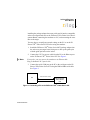
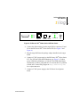
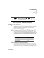
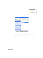
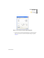
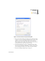
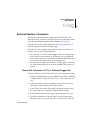
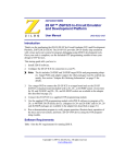
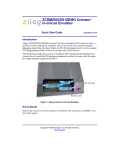
Z8 Encore! XP® F64xx Series Flash Microcontrollers
In-Circuit Emulator
User Manual
UM016804-0208
Copyright ©2008 by Zilog®, Inc. All rights reserved.
www.zilog.com
In-Circuit Emulator
User Manual
ii
Revision History
Each instance in the Revision History table reflects a change to this document from its previous revision. For more details, refer to the corresponding pages and appropriate links in the table below.
Date
February
2008
UM016804-0208
Revision
Level
04
Description
Changed product name and
used latest template.
Page
Number
All
Revision History
In-Circuit Emulator
User Manual
iii
Table of Contents
Introduction . . . . . . . . . . . . . . . . . . . . . . . . . . . . . . . . . . . . . . . . . . . . . . . . . .1
Kit Contents . . . . . . . . . . . . . . . . . . . . . . . . . . . . . . . . . . . . . . . . . . . . . . . . .1
Requirements . . . . . . . . . . . . . . . . . . . . . . . . . . . . . . . . . . . . . . . . . . . . . . . .2
Install the Software . . . . . . . . . . . . . . . . . . . . . . . . . . . . . . . . . . . . . . . . . . . .2
Install the Hardware . . . . . . . . . . . . . . . . . . . . . . . . . . . . . . . . . . . . . . . . . . .2
Configure the Hardware . . . . . . . . . . . . . . . . . . . . . . . . . . . . . . . . . . . . . . . .6
Setting Jumpers on the Z8 Encore! XP® F64xx Series ICE . . . . . . . . . .6
Setting Up Ethernet Communications . . . . . . . . . . . . . . . . . . . . . . . . . .6
Running a Sample Project . . . . . . . . . . . . . . . . . . . . . . . . . . . . . . . . . . . . . .14
Running a Simple Trace . . . . . . . . . . . . . . . . . . . . . . . . . . . . . . . . . . . .16
Using Events to Start and Stop a Trace . . . . . . . . . . . . . . . . . . . . . . . .17
Single-Stepping Through a Program . . . . . . . . . . . . . . . . . . . . . . . . . .18
Peek/Poke Registers . . . . . . . . . . . . . . . . . . . . . . . . . . . . . . . . . . . . . . .18
Peek/Poke Memory . . . . . . . . . . . . . . . . . . . . . . . . . . . . . . . . . . . . . . .18
LED Indicators . . . . . . . . . . . . . . . . . . . . . . . . . . . . . . . . . . . . . . . . . . . . . .19
External Interface Connectors . . . . . . . . . . . . . . . . . . . . . . . . . . . . . . . . . . .20
How to Set Connector J11 Pin 1, External Trigger Out . . . . . . . . . . . .20
How to Set Connector J11 Pin 3, External Trigger In . . . . . . . . . . . . .21
Adapter Ordering Information . . . . . . . . . . . . . . . . . . . . . . . . . . . . . . . . . .21
Customer Support. . . . . . . . . . . . . . . . . . . . . . . . . . . . . . . . . . . . . . . 23
UM016804-0208
Table of Contents
In-Circuit Emulator
User Manual
1
Introduction
The Zilog Z8 Encore! XP® F64xx Series In-Circuit Emulator (ICE) provides Z8 Encore! XP® F64xx Series MCU emulation with a trace and
event system for program debugging using ZDS II development tools.
This user manual tells you how to do the following:
1. Install ZDS II software.
2. Configure the Z8 Encore! XP® F64xx Series ICE for connection to
your PC.
3. Connect the Z8 Encore! XP® F64xx Series ICE to a target board
using a Z8 Encore! XP® F64xx Series MCU package adapter.
4. Run a demonstration program to verify proper operation and illustrate
basic operation of the trace and event system.
Kit Contents
UM016804-0208
•
•
•
•
One (1) Z8 Encore! XP® F64xx Series In-Circuit Emulator.
•
One (1) target POD with ribbon cables to connect the Z8 Encore!
XP® F64xx Series ICE to the package adapter that came with your
kit. (To obtain adapters for other Z8 Encore! XP® F64xx Series MCU
packages, refer to “Adapter Ordering Information” on page 21.)
•
•
Two (2) 5V AC power supply and adapters
One (1) DB9-to-DB9 serial I/O cable.
One (1) CAT-5 crossover cable.
One (1) 40-pin PDIP, 44-pin LQFP, 44-pin PLCC, 64-pin LQFP, 68pin PLCC, or 80-pin QFP package adapter (depending on the emulator model you ordered).
One (1) ZDS II Installation CD-ROM
In-Circuit Emulator
User Manual
2
Requirements
Table 1 lists the PC requirements for running ZDS II.
Table 1. ZDS II System Requirements
Recommended Configuration
Minimum Configuration
•
•
•
•
•
•
•
•
•
• PC running MS Windows 98SE/WinNT 4.0–
SP6/Win2000–SP3/WinXP–SP1
• Pentium II/233 MHz processor
• 96 MB RAM
• 25 MB hard disk space
• Super VGA video adapter
• CD-ROM drive
• Ethernet port
• One or more RS-232 communications ports
• Internet browser (Internet Explorer or
Netscape)
PC running MS Windows XP, SP1
Pentium III/500 MHz processor
128 MB RAM
40 MB hard disk space
Super VGA video adapter
CD-ROM drive
Ethernet port
One or more RS-232 communications ports
Internet browser (Internet Explorer or
Netscape)
Install the Software
Follow these steps to install ZDS II with the ANSI C-Compiler.
1. Insert the ZDS II CD into your computer’s CD-ROM drive.
DemoShield launches automatically. If it does not automatically
launch, go to the root of the CD-ROM and double-click the file
launch.exe.
2. DemoShield provides several installation choices. Select “Install ZDS
II” to install now. You can install other software and accompanying
documentation later.
3. Follow the instructions on the screen to complete the installation.
Install the Hardware
The Z8 Encore! XP® F64xx Series In-Circuit Emulator features an Ethernet interface and an RS-232 serial port. Hardware installation consists of
UM016804-0208
In-Circuit Emulator
User Manual
3
installing the package adapter that came with your kit into the compatible
socket on a target board such as the Z8 Encore! XP® F64xx Series Development Board; connecting the emulator to a PC; and connecting the emulator to the target.
You may have to reconfigure network settings on the PC or on the Z8
Encore! XP® F64xx Series ICE before using the emulator.
1. Install the Z8 Encore! XP® F64xx Series MCU package adapter into
the socket on your target board, being sure to line up the guide pins
with the guide pin holes on the socket.
2. Connect the CAT-5 crossover cable from the PC to the Ethernet port
on the Z8 Encore! XP® F64xx Series ICE. See Figure 1.
Note:
If you prefer, you can connect the emulator to an Ethernet hub
using a standard CAT-5 patch cable.
3. Connect the serial COM port on the PC to the serial port on the Z8
Encore! XP® F64xx Series ICE using the DB9-to-DB9 serial cable.
See Figure 2.
PC
CAT-5 Crossover Cable
DB9-to-DB9 Cable
Z8 Encore! XP
F64xx Series
ICE
Figure 1. Connecting a PC to the Z8 Encore! XP® F64xx Series ICE
UM016804-0208
In-Circuit Emulator
User Manual
4
3.3 VDC OK
Link
DB9 connector
LAN
Ethernet
(RJ-45)
Reset
USB
(unused) Switch
1.8 VDC Ok
Ext
Pwr
In
Figure 2. Z8 Encore! XP® F64xx Series ICE Rear Panel
4. Connect the ribbon cables from the target POD to connectors J2 and
J10 on the Z8 Encore! XP® F64xx Series ICE. (See Figure 3 and
Figure 4.)
5. Plug the target POD into the package adapter installed on the target
board.
6. Connect a 5 VDC power supply to the Z8 Encore! XP® F64xx Series
ICE. The ICE Run LED should illuminate (see Figure 5). If either
power LED fails to illuminate, or if the ICE Fail LED either blinks
continuously or fails to extinguish after 15 seconds, there is a problem
with the unit. Contact Zilog support at http://www.zilog.com/
for a replacement unit.
7. Connect a 5 VDC power supply to the Z8 Encore! development
board.
UM016804-0208
In-Circuit Emulator
User Manual
5
Target POD
and Adapter
Assembly
Figure 3. Connecting the Z8 Encore! XP® F64xx Series ICE to the Target POD and
Adapter Assembly (Typical Connection Shown)
J2
Pin 1
J14
Pin 1
J12
J11
J10
Unit Front
Figure 4. Z8 Encore! XP® F64xx Series ICE Top View
UM016804-0208
D1
In-Circuit Emulator
User Manual
6
ICE Run
J11 and J14
J10 and J2
J12
ICE Fail
Figure 5. Z8 Encore! XP® F64xx Series ICE Front-Panel
Configure the Hardware
Configuring the Z8 Encore! XP® F64xx Series ICE consists of selecting
emulator jumper options and setting up Ethernet communications
between the emulator and your PC.
Setting Jumpers on the Z8 Encore! XP® F64xx Series ICE
There is one jumper on the Z8 Encore! XP® F64xx Series ICE. Jumper
J12 allows you to select whether the emulator Watch-Dog Timer uses the
32-kHz internal oscillator or is programmable using the settings in ZDS
II.
Table 2. Jumper J12 Settings on the Z8 Encore! XP® F64xx Series ICE
Watch-Dog Timer...
Jumper Position
uses the 32-kHz internal oscillator
1 - 2 (default)
not implemented
3-4
Setting Up Ethernet Communications
The default IP address and subnet mask of the Z8 Encore! XP® F64xx
Series ICE are 192.168.1.50 and 255.255.255.0, respectively. To enable
communication between the PC running ZDSII and the Z8 Encore! XP®
UM016804-0208
In-Circuit Emulator
User Manual
7
F64xx Series ICE, you must either change the PC’s Ethernet settings to
match those of the Z8 Encore! XP® F64xx Series ICE or vice versa.
If using the PC in a stand-alone configuration, set the PC’s IP address to
192.168.1.21 and its subnet mask to 255.255.255.0. See “Changing the
PC’s Settings to Match the Z8 Encore! XP® F64xx Series ICE” on
page 7.
If working in a networked environment, set the Z8 Encore! XP® F64xx
Series ICE IP address and subnet mask to match the existing network
setup. See “Changing Z8 Encore! XP® F64xx Series ICE Settings to
Match the PC” on page 12.
Changing the PC’s Settings to Match the Z8 Encore! XP®
F64xx Series ICE
After completing the following steps to change the PC’s Ethernet settings,
proceed to Running a Sample Project on page 14.
Note:
The following instructions are for MS Windows XP. If your Windows operating system is different, refer to your MS Windows OS
online help for details.
1. Open the Windows Control Panel and double-click the Network Connections icon. The Network Connections dialog box appears (see
Figure 6).
UM016804-0208
In-Circuit Emulator
User Manual
8
Figure 6. The Network Dialog Box
2. In the panel labeled LAN or High-Speed Internet, double-click the
Local Area Connection icon. The Local Area Connection Status dialog box appears (Figure 7).
UM016804-0208
In-Circuit Emulator
User Manual
9
Figure 7. The Local Area Connection Status Dialog Box
3. In the Local Area Connection Status dialog box, click the Properties
button. The Local Area Connection Properties dialog box appears
(Figure 8).
UM016804-0208
In-Circuit Emulator
User Manual
10
Figure 8. The Local Area Connection Properties Dialog Box
4. In the panel labeled This connection uses the following items:, select
the Internet Protocol (TCP/IP) item to highlight it, and click the Properties button. The Internet Protocol (TCP/IP) Properties dialog box
appears (Figure 9).
UM016804-0208
In-Circuit Emulator
User Manual
11
Figure 9. The Internet Protocol Properties Dialog Box
5. Enter values for the IP address and subnet mask to match those shown
in Figure 4. Leave any remaining fields blank. In this example, an IP
address of 192.168.1.21 and a subnet mask of 255.255.255.0 are
being assigned to the PC. These values place the PC on the same network as the Z8 Encore! XP® F64xx Series ICE unit.
6. Click OK and restart the PC. Refer to “Changing Z8 Encore! XP®
F64xx Series ICE Settings to Match the PC” on page 12 for information on checking the Z8 Encore! XP® F64xx Series ICE IP address.
7. Proceed to “Running a Sample Project” on page 14.
UM016804-0208
In-Circuit Emulator
User Manual
12
Changing Z8 Encore! XP® F64xx Series ICE Settings to Match
the PC
1. Connect the PC serial port to the Z8 Encore! XP® F64xx Series ICE
serial port using the DB9-to-DB9 serial cable.
2. Launch HyperTerminal on the PC by selecting Start --> Programs -->
Accessories --> Communications --> HyperTerminal.
3. In the Connect To dialog, set the Connect Using: drop-down menu to
match the COM port to which the Z8 Encore! XP® F64xx Series ICE
is connected. Click OK.
4. A COM Properties dialog appears. Enter the following port settings
and click OK.
Bits per second: 57600
Data bits:
8
Parity:
None
Stop bits:
2
Flow control:
None
5. HyperTerminal should automatically attempt a connection. If not,
select Call --> Connect.
6. While holding down the z key (lowercase) on the PC’s keyboard,
press the RESET button on the back panel of the Z8 Encore! XP®
F64xx Series ICE. Releasing the z key displays a Z8 Encore! XP®
F64xx Series ICE console boot-up message in HyperTerminal, followed by the > prompt. A typical boot-up message is shown below.
1540096 bytes physical mem
RAM Block0 from 100000 to 17ffff
Flash/ ROM from
8000 to fffff
172701 bytes Code
15947 bytes Data
321128 bytes user stack/heap space
Starting at 131991
UM016804-0208
In-Circuit Emulator
User Manual
13
Zilog TCP/IP Software Suite v1.1
Copyright (C) 2003 Zilog Inc.
All Rights Reserved
clock enabled
IP Address: 192.168.1.50
IP Subnet: 192.168.1.0/255.255.255.0
IP Gateway: 192.168.1.254
Z8 Encore! ICE Communication Module 1.0
Copyright © 2001-2003 Zilog, Inc.
All Rights Reserved.
Z8 Encore! Emulator Configuration Console
Type 'H' for help
Note:
The emulator console prompt is not case-sensitive.
7. At the prompt, type H and press ENTER. The following message
should appear:
> H
H
I
S
G
P
V
B
F
C
D
A
W
UM016804-0208
display this Help
change Ipaddress
change ipSubnet mask
change ipGateway
change Portnumber
change dtli Variable count
change dtli Buffer size
load deFault settings
display Current settings
toggle Dhcp option
toggle pAssword
change passWord
In-Circuit Emulator
User Manual
14
R
Reset emulator
>
8. Use the I command to change the Z8 Encore! XP® F64xx Series ICE
IP address to one that is compatible with the PC. Use caution to avoid
creating a conflicting IP address.
9. Use the S command to change the Z8 Encore! XP® F64xx Series ICE
subnet mask to one that is compatible with the PC. Typically, the subnet mask is the same as that of the PC.
10. Use the G command to change the Z8 Encore! XP® F64xx Series ICE
Gateway to one that is compatible with the PC. Typically, the gateway
is the same as that of the PC.
11. Use the C command to verify the new settings.
12. Exit HyperTerminal.
13. Cycle the power on the Z8 Encore! XP® F64xx Series ICE for the
new settings to take effect.
The hardware is now configured and ready for application development.
Running a Sample Project
After installing the ZDS II software and setting up the hardware, you can
run a sample software project to verify proper emulator operation and
experiment with the trace and event system. The sample project icedemo.pro is included in the ZDS II sample directory, located in:
c:\Program Files\ZiLOG\ZDSII_<product>_<version>
\samples\<processor type>_<demo name>
Start ZDS II for the Z8 Encore! XP® F64xx Series ICE and follow the
instructions below to run icedemo.pro.
UM016804-0208
In-Circuit Emulator
User Manual
15
Note:
The following procedures require that the emulator be connected
to a target board, such as the Z8 Encore! F64xx Series Development Board.
1. Select File --> Open Project--> c:\Program
Files\ZDSII_Z8Encore!_F642X_Emulator_4.6.x\samples\FZ8F642x_ICEDemo\src
\icedemo.pro.
2. Double-click main.c in the Project Files window.
3. Open Project --> Settings.
4. In the General tab, verify the CPU field is set to Z8F6423.
5. In the Debugger: Select Z8 Encore! Emulator and then click the Configure Driver button.
6. The Encore! Emulator dialog box appears. The IP Address field displays a default IP address, 192.168.1.50. Enter the Z8 Encore! XP®
F64xx Series ICE IP address you configured during hardware install.
Leave the other settings as they are.
7. Select the Target VCC voltage. If the emulator is connected to the Z8
Encore! XP F64xx Series development board, select 3.0V. If running
the emulator in standalone mode, select Standalone. If the emulator is
connected to a custom target, select the voltage appropriate for that
target.
Note:
The emulator’s voltage comparator is designed as a target power
sensor, not as a precision voltage measurement device. If you set
the Target VCC to match your target and the target’s voltage drifts
downward, the power sensor may no longer detect it. The emulator may therefore not connect to the target. In such cases, set the
Target VCC voltage progressively lower until you get a good connection.
UM016804-0208
In-Circuit Emulator
User Manual
16
8. Select the appropriate clock frequency or enter the clock frequency in
the Other field. This should match the 20-MHz Clock Oscillator on
Y4 of the emulator.
Note:
The emulator clock cannot be supplied from the Target application
Board.
9. Click OK to close the Z8 Encore! Emulator dialog box.
10. Click OK to close the Project Settings dialog box.
11. Open the Trace window by selecting View --> Debug Windows -->
Trace.
12. Make sure that the Event System is disabled (The Edit --> Event System command does not have a check mark to the left of the command).
13. In the Trace window, click the Clear Trace button.
14. Build the project now by selecting Build --> Build, or by pressing F7.
Note:
The following steps describe two ways to use the trace and event
system. For details on running the trace and event system, refer to
the ZDS II online help and the ZDS II—Z8 Encore! User Manual,
located in the docs directory of the ZDS II CD-ROM.
Running a Simple Trace
Now we’ll run a simple trace by starting the program, then stopping it and
viewing the trace buffer. Click the Go button in the toolbar. ZDS II communicates with the emulator, then runs the demo program. When the trace
buffer is full, the “CPU breaks on Trace-Buffer Full” message displays in
the Debug window. Click Get Frames to display the trace information.
View the trace window and you’ll see that all program cycles are logged.
Click the Options button in the Trace window to select the way in which
you’d like the trace displayed.
UM016804-0208
In-Circuit Emulator
User Manual
17
Using Events to Start and Stop a Trace
1. Now we’ll define a pair of events to automatically start and stop a
trace. Use this feature, for example, to trace execution of a particular
module in your program and see the context in which the module is
running with respect to other program modules.
2. Select Tools --> Trace and Event System. Click the Enable event system check box, and click the Break when trace buffer is full check
box.
3. Select Event 0. We’ll use this as the event to trigger a trace.
4. In the When: section, click the Program counter check box and set the
Program Counter to 03F2 and the Mask to FFFF.
5. In the Then: section, click the Trace check box and select the On
radio button.
6. Select Event 1. We’ll use this as the event to break the trace.
7. In the When: section, click the Program counter check box and set the
Program Counter to 041D and the Mask to FFFF.
8. In the Then: section, click the Trace check box. Select the Off radio
button, and select the AND BREAK radio button. Click the OK button.
9. In the Trace window, click the Clear Trace button.
10. Reset the Debugger by clicking the Reset button in the toolbar, or by
selecting Build --> Debug --> Reset.
11. Run the Debugger by clicking the Go button or by selecting Build -->
Debug --> Go.
12. Wait for the program execution to break.
UM016804-0208
In-Circuit Emulator
User Manual
18
13. Click Get Frames to display the trace information. Study the contents
of the Trace window to see how the trace and event system reports
program execution for the segment we set using the Event tools.
Single-Stepping Through a Program
1. ZDS II provides a simple mechanism for single-stepping through a
program. First, reset the program to Main() by either the Reset icon or
with Build --> Debug --> Reset. Set the Reset to Main option by
selecting Tools --> Options. In the Options window, select the Debugger tab and select the Reset to symbol ‘main’ check box.
2. To step through the program one instruction at a time, use F11 or click
the
button in the Debug toolbar (also accessible by selecting Build
--> Debug --> Step Into).
Peek/Poke Registers
1. ZDS II makes it easy for you to set and read emulator register contents. With the ICEDEMO project open and ZDS II connected to the
emulator (target), select View --> Debug Windows --> Registers.
2. In the Registers window, double-click the value of any register and
type in a new value.
3. Press Enter. The new value displays in red.
Refer to the ZDS II—Z8 Encore! User Manual on the ZDS II CD-ROM
and the ZDS II online help for further information on setting and reading
register values.
Peek/Poke Memory
1. ZDS II also allow to set and read memory contents. With the ICEDEMO project open and ZDS II connected to the emulator (target),
select View --> Debug Windows --> Memory.
UM016804-0208
In-Circuit Emulator
User Manual
19
2. In the Memory window, double-click the value you want to change
and type in a new value. (Values begin in the second column after the
Address column.)
3. Press Enter. The new value displays in red.
Refer to the ZDS II—Z8 Encore! User Manual on the ZDS II CD-ROM
and the ZDS II online help for further information on setting, filling, and
reading memory.
LED Indicators
There are three sets of dual LED indicators on the Z8 Encore! XP® F64xx
Series ICE (see Figure 2 and Figure 5):
UM016804-0208
•
Dual LED D1 on the front panel indicates emulator status. If the top
LED is lit, the emulator is functioning normally. If the bottom LED is
lit, the emulator is not functioning properly. Contact technical support
at http://www.zilog.com for assistance.
•
Dual LED D2 on the rear panel indicates the status of internal voltages. The top LED indicates that the 3.3 VDC voltage is okay. The
bottom LED indicates that the 1.8 VDC voltage is okay (you may
have to turn the ambient lighting off to see the status of the 1.8 VDC
LED). If either LED is not lit, contact technical support at
http://www.zilog.com for assistance.
•
Dual LED D3 on the rear panel indicates Ethernet status. The top
LED indicates that the Ethernet connection is live (Link). The bottom
LED indicates that data is being transferred across the connected network.
In-Circuit Emulator
User Manual
20
External Interface Connectors
There are four external interface connectors on the Z8 Encore! XP®
F64xx Series ICE. Connectors J2 and J10 are used to connect the emulator to the target POD and adapter board assembly. (See Figure 4.)
Connector J14 on the emulator front panel (see Figure 4 and Figure 5)
provides a ground connection on all three pins.
Connector J11 on the emulator front panel (see Figure 4 and Figure 5)
provides access to the following functions:
•
Pin 1 provides a 3.3 VDC external trigger out for use in triggering a
device such as a logic analyzer or oscilloscope. Pin 1 is under software control, and can be set to activate through the ZDS II trace and
event system. The trigger can be set to toggle or pulse.
•
Pin 3 provides an input for an external 3.3 VDC trigger in, allowing
use of an external trigger as an event for the ZDS II trace and event
system.
How to Set Connector J11 Pin 1, External Trigger Out
To use the Z8 Encore! XP® F64xx Series ICE external trigger out feature:
1. With the ICEDEMO project open in ZDS II as described in “Running
a Sample Project” on page 14, select Tools --> Trace and Event System.
2. In the Trace and Event System window, select an Event entry and
specify the event parameters in the When: section.
3. In the Then: section of the Trace and Event System window, check
the Trigger Out box to enable the Toggle and Pulse settings.
4. Select the radio button for the Trigger Out setting you wish to use.
5. Click the OK button to set the trace and event system parameters.
When the event you set up occurs, pin 1 of connector J11 either togUM016804-0208
In-Circuit Emulator
User Manual
21
gles (changes state) or pulses, depending on what you specified for
Trigger Out.
How to Set Connector J11 Pin 3, External Trigger In
To use the Z8 Encore! XP® F64xx Series ICE external trigger in feature:
1. With the ICEDEMO project open in ZDS II as described in “Running
a Sample Project” on page 14, select Tools --> Trace and Event System.
2. In the Trace and Event System window, select an Event entry. In the
When section, check the Trigger In box.
3. In the Then section, set the parameters you want to use.
4. Click the OK button to set the trace and event system parameters.
When the external device you are using sets pin 3 of connector J11 to
3.3VDC, an event is generated in the ZDS II trace and event system.
Adapter Ordering Information
Use the following part numbers to order additional package adapters.
UM016804-0208
•
Z8F64210100ZDP, Z8 Encore! XP® F64xx Series 40-pin PDIP ICE
Adapter
•
Z8F64210100ZDA, Z8 Encore! XP® F64xx Series 44-pin LQFP ICE
Adapter
uses Adapters.com 110-72662-10
•
Z8F64210100ZDV, Z8 Encore! XP® F64xx Series 44-pin PLCC ICE
Adapter
•
Z8F64220100ZDA, Z8 Encore! XP® F64xx Series 64-pin LQFP ICE
Adapter
uses Adapters.com 110-7334-10
In-Circuit Emulator
User Manual
22
UM016804-0208
•
Z8F64220100ZDV, Z8 Encore! XP® F64xx Series 68-pin PLCC ICE
Adapter
•
Z8F64230100ZDF, Z8 Encore! XP® F64xx Series 80-pin QFP ICE
Adapter
uses Adapters.com 110-7405-10
In-Circuit Emulator
User Manual
23
Customer Support
For answers to technical questions about the product, documentation, or
any other issues with Zilog’s offerings, please visit Zilog’s Knowledge
Base at http://www.zilog.com/kb.
For any comments, detail technical questions, or reporting problems,
please visit Zilog’s Technical Support at http://support.zilog.com.
UM016804-0208
In-Circuit Emulator
User Manual
24
Warning: DO NOT USE IN LIFE SUPPORT
LIFE SUPPORT POLICY
ZILOG'S PRODUCTS ARE NOT AUTHORIZED FOR USE AS CRITICAL
COMPONENTS IN LIFE SUPPORT DEVICES OR SYSTEMS WITHOUT THE
EXPRESS PRIOR WRITTEN APPROVAL OF THE PRESIDENT AND GENERAL
COUNSEL OF ZILOG CORPORATION.
As used herein
Life support devices or systems are devices which (a) are intended for surgical implant
into the body, or (b) support or sustain life and whose failure to perform when properly
used in accordance with instructions for use provided in the labeling can be reasonably
expected to result in a significant injury to the user. A critical component is any
component in a life support device or system whose failure to perform can be reasonably
expected to cause the failure of the life support device or system or to affect its safety or
effectiveness.
Document Disclaimer
©2007 by Zilog, Inc. All rights reserved. Information in this publication concerning the
devices, applications, or technology described is intended to suggest possible uses and
may be superseded. ZILOG, INC. DOES NOT ASSUME LIABILITY FOR OR
PROVIDE A REPRESENTATION OF ACCURACY OF THE INFORMATION,
DEVICES, OR TECHNOLOGY DESCRIBED IN THIS DOCUMENT. ZILOG ALSO
D O E S N O T A S S U M E L I A B I L I T Y F O R I N T E L L E C T U A L P R O P E RT Y
INFRINGEMENT RELATED IN ANY MANNER TO USE OF INFORMATION,
DEVICES, OR TECHNOLOGY DESCRIBED HEREIN OR OTHERWISE. The
information contained within this document has been verified according to the general
principles of electrical and mechanical engineering.
Z8, Z8 Encore!, Z8 Encore! XP, Z8 Encore! MC, Crimzon, eZ80, and ZNEO are
trademarks or registered trademarks of Zilog, Inc. All other product or service names are
the property of their respective owners.
UM016804-0208