1
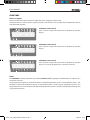
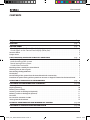
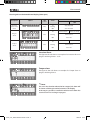
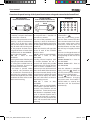
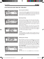
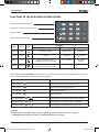
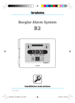
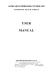
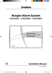
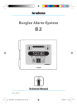
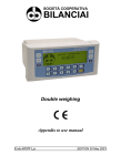
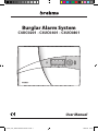
Burglar Alarm System
C4UC0201 - C4UC0401 - C4UC0801
User Manual
08-02-10/24800310
C4UC_Uten_EXPO 24800310 08-02-10.indd 1
08/02/10 10:53
User manual
GLOSSARY
Zones or Inputs
Zones or Inputs mean the sources from which the alarms originate, which can be:
movement sensors, contact sensors applied on doors and windows and any other alarm detector that can be
connected to the System.
C4UC0201 Control Panel
It has 2 Zones or Inputs that are shown in the lower part of the
display.
C4UC0401 Control Panel
It has 4 Zones or Inputs that are shown in the lower part of the
display.
C4UC0801 Control Panel
It has 8 Zones or Inputs that are shown in the lower part of the
display and can be grouped into a maximum of 4 Areas.
Areas
The C4UC0801 control panel makes it possible (Installer's task) to group the available Zones or Inputs into a
maximum of 4 Areas.
It is possible, for example, to associate the Zones to which the perimeter sensors are connected to Area 1, and
the Zones to which the volumetric sensors are connected to Area 2; in this way, by activating only Area 1 it is
be possible to move around freely inside the building while the System is armed to specifically protect against
any possible intrusions.
2
C4UC_Uten_EXPO 24800310 08-02-10.indd 2
08/02/10 10:53
User manual
CONTENTS
Chapter
Page
GLOSSARY
page
CONTROL PANEL
page
Visual signals on the Control Panel display (upper part). . . . . . . . . . . . . . . . . . . . . . . . . . . . . . . . . . . . . . . . .
Visual signals on the Control Panel display (lower part) . . . . . . . . . . . . . . . . . . . . . . . . . . . . . . . . . . . . . . . . .
Intrusion Alarm . . . . . . . . . . . . . . . . . . . . . . . . . . . . . . . . . . . . . . . . . . . . . . . . . . . . . . . . . . . . . . . . . . . . . . . . . . . . . . . . . . . . .
Tamper alarm. . . . . . . . . . . . . . . . . . . . . . . . . . . . . . . . . . . . . . . . . . . . . . . . . . . . . . . . . . . . . . . . . . . . . . . . . . . . . . . . . . . . . . .
USER FUNCTIONS AVAILABLE USING KEYS OR KEYPADS
page
2
4
4
5
5
5
6
total arming of the system. . . . . . . . . . . . . . . . . . . . . . . . . . . . . . . . . . . . . . . . . . . . . . . . . . . . . . . . . . . . . . . . . . . . . . .
total disarming of the system. . . . . . . . . . . . . . . . . . . . . . . . . . . . . . . . . . . . . . . . . . . . . . . . . . . . . . . . . . . . . . . . . . . .
forced arming of the system. . . . . . . . . . . . . . . . . . . . . . . . . . . . . . . . . . . . . . . . . . . . . . . . . . . . . . . . . . . . . . . . . . . . .
Assault Alarm activation. . . . . . . . . . . . . . . . . . . . . . . . . . . . . . . . . . . . . . . . . . . . . . . . . . . . . . . . . . . . . . . . . . . . . . . . .
Resetting alarms saved by the Control Panel. . . . . . . . . . . . . . . . . . . . . . . . . . . . . . . . . . . . . . . . . . . . . . . . . . . . . . . . . .
Silencing acoustic alarm signals. . . . . . . . . . . . . . . . . . . . . . . . . . . . . . . . . . . . . . . . . . . . . . . . . . . . . . . . . . . . . . . . . . . . . .
Deactivating the keypad Buzzer. . . . . . . . . . . . . . . . . . . . . . . . . . . . . . . . . . . . . . . . . . . . . . . . . . . . . . . . . . . . . . . . . . . . . .
Test Display. . . . . . . . . . . . . . . . . . . . . . . . . . . . . . . . . . . . . . . . . . . . . . . . . . . . . . . . . . . . . . . . . . . . . . . . . . . . . . . . . . . . . . . . .
Partial arming of the System from the Control Panel with a contact key . . . . . . . . . . . . . . . . . . . . . . . . . . . . . . . .
Procedure for partial arming of the System from inserters or keypads external to the Control Panel . . . . .
6
6
6
6
7
7
7
7
7
8
OPERATION OF THE DISPLAY IN THE USER MENU
page
9
FUNCTIONS AVAILABLE FROM THE "USER MENU"
page
Accessing the User Menu . . . . . . . . . . . . . . . . . . . . . . . . . . . . . . . . . . . . . . . . . . . . . . . . . . . . . . . . . . . . . . . . . . . . . . . . . .
Key Programming. . . . . . . . . . . . . . . . . . . . . . . . . . . . . . . . . . . . . . . . . . . . . . . . . . . . . . . . . . . . . . . . . . . . . . . . . . . . . . . . .
Deleting one or all keys. . . . . . . . . . . . . . . . . . . . . . . . . . . . . . . . . . . . . . . . . . . . . . . . . . . . . . . . . . . . . . . . . . . . . . . . . . . .
Inserting a code via the keypad (optional). . . . . . . . . . . . . . . . . . . . . . . . . . . . . . . . . . . . . . . . . . . . . . . . . . . . . . . . . .
Deleting a code via the keypad (optional) . . . . . . . . . . . . . . . . . . . . . . . . . . . . . . . . . . . . . . . . . . . . . . . . . . . . . . . . . .
Test Siren. . . . . . . . . . . . . . . . . . . . . . . . . . . . . . . . . . . . . . . . . . . . . . . . . . . . . . . . . . . . . . . . . . . . . . . . . . . . . . . . . . . . . . . . .
Password for activation via SMS. . . . . . . . . . . . . . . . . . . . . . . . . . . . . . . . . . . . . . . . . . . . . . . . . . . . . . . . . . . . . . . . . . . .
Exiting from the User Menu . . . . . . . . . . . . . . . . . . . . . . . . . . . . . . . . . . . . . . . . . . . . . . . . . . . . . . . . . . . . . . . . . . . . . . .
10
10
10
11
11
11
12
12
10
OPTIONAL INSERTER BXINIR AND INFRARED KEY BXKEIR01
page 13
FUNCTIONS OF THE ADDITIONAL KEYPAD BXTAIN
page 14
3
C4UC_Uten_EXPO 24800310 08-02-10.indd 3
08/02/10 10:53
User manual
CONTROL PANEL
CONTROL KEYPAD
INSERTER FOR
CONTACT KEY
RECEIVER FOR
OPTIONAL IR INSERTER
KEY FOR CONTACT INSERTER
Visual signals on the Control Panel display (upper part)
Meaning
LED colour
Status
Network
presence
Green
Lit
Flashing
Off
230 V AC present
--------------No network
Battery status
Yellow
Lit
Flashing
Off
Battery run down (in the case of no network)
--------------Battery Charged (in the case of no network)
ON/OFF
Green
Lit
Flashing
Off
Sabotage
Red
Lit
Flashing
Off
Alarm
Red
Lit
Flashing
Off
Fault
Yellow
Lit
Flashing
Off
Exclusion
Yellow
Lit
Flashing
Off
At least one zone excluded
-----------------------------
-------------------------------------------
Maintenance
Yellow
Lit
Flashing
Off
-------------------------------------------
Maintenance
-----------------------------
Description
Symbol
Control Panel ON
system armed
In / Out time
--------------
Control Panel OFF
--------------------------system disarmed
Sabotage in progress
Tamper alarm saved
No sabotage in progress
Alarm in progress
System Not Ready
Alarm Saved
No alarm
Generic fault (fuse F2 / external bus)
Fault saved
No Fault
Excluded Zones Display
When the LED of the
icon is lit, this indicates the division of
the system, that is, the exclusion of some zones (see the example to the left).
LED lit + "E" on the display = Zone Excluded
LED off = Zone Included
4
C4UC_Uten_EXPO 24800310 08-02-10.indd 4
08/02/10 10:53
User manual
Visual signals on the Control Panel display (lower part)
Description
Symbol
Exclusion
Status of the
zones
Meaning
LED
colour
Status
Red
Lit
Flashing
Off
Lit
Burglar
Alarm
Red
Red
Control Panel
OFF
Zone excluded
---------Zone Included
Zone in alarm
Zone not ready
Flashing
Alarm Saved
Off
Zone idle
Lit
Tamper
Alarm
Control Panel ON
Zone in alarm
Zone not ready
Flashing
Alarm Saved
Off
Zone idle
Intrusion Alarm
The figure to the side shows an example of an Intrusion Alarm in
progress involving Zones 1 and 2.
Tamper alarm
The figure to the side shows an example of a Tamper alarm in
progress involving Zone 2.
.Note:
If a sensor has found an alarm that has stopped, the alarm will
be shown as flashing instead of constant on the display.
In this way it is possible to establish in which zone the alarm has
occurred even if it is no longer in progress.
5
C4UC_Uten_EXPO 24800310 08-02-10.indd 5
08/02/10 10:53
User manual
USER FUNCTIONS AVAILABLE USING KEYS OR KEYPADS
Via Contact Key
from the Control Panel Inserter
or from an External Inserter
Via Infrared Key
from the Control Panel Inserter
(optional) or from an External
Inserter
Via Keypad
1
2
3
4
5
6
7
8
9
0
1
2
3
4
5
6
7
8
9
1
2
3
4
5
6
FORCED ARMING OF THE SYSTEM*
4
54
65
6
With the system disarmed, send
a impulse with a duration of 0.5
to 3 seconds, and then a second
impulse of the same duration.
7
87
98
9
TOTAL ARMING OF THE SYSTEM
With the system disarmed, insert
and remove a valid key.
With the system disarmed, send
an impulse with a duration of 0.5
to 3 seconds.
With the system disarmed, type:
0 +
<valid code>
TOTAL DISARMING OF THE SYSTEM
With the system armed (even partially), insert and remove a valid
key.
With the system disarmed, insert
a valid key, and remove it keeping
the button pressed.
With the system armed (even partially), send an impulse with a
duration of 0.5 to 3 seconds.
ACTIVATION OF THE ASSAULT
Insert a valid key with the button already pressed and then
remove the key.
With the system armed (even par8
9
7
tially), type:
3
3
1
1
2
2
0 +
<valid code>
With the system disarmed, type:
0 +
0 +
<valid code>
1
2
13
2
3
ALARM**4
5
46
5
6
8
79
8
9
7
Type:
0
0 +
+ <valid
code>
* "Forced Arming" of the system refers to the possibility of arming the system even if one or more Zones are
in alarm status; this choice implies that the Zones in alarm status when the “Forced Arming” is performed
will be ignored by the system until the next activation cycle.
** The appropriately programmed "Assault Alarm" is able to activate signals that are useful for requesting
help (for example, a telephone dialler) without alarming a possible attacker.
WARNING
If forced arming is enabled during installation, there will be a few seconds' delay when the Control Panel is
activated in order to give the User time to perform the necessary operations for accessing the Forced Arming
procedure.
6
C4UC_Uten_EXPO 24800310 08-02-10.indd 6
08/02/10 10:53
User manual
Resetting alarms saved by the Control Panel
As an example, the figure to the side shows an "Intrusion Alarm" in Zone1;
the fact that the LED and "A" are flashing indicates that the alarm has
already occurred and has been saved.
To reset saved alarms proceed as follows:
With a contact key
• keep the q button held down, insert a valid contact key, remove the key, release the q button;
In any case the signals are reset automatically the next time that the system is armed.
Silencing acoustic alarm signals
Acoustic alarm signals are silenced by inserting a valid key and pressing the l pushbutton without changing the
activation status of the Control Panel, or whenever the system is disarmed.
Deactivating the keypad Buzzer
This function can be performed only on the Control Panel.
To deactivate control panel buzzer simply keep the q button pressed for at least 3 seconds; to reactivate it do
the same.
Test Display
This function can be performed only on the Control Panel.
To test the display just keep the p button pressed for at least 3 seconds: all the graphical elements of the
display and the lighting LED will come on for 1 second.
Partial arming of the System from the Control Panel with a contact key
With the system disarmed or armed, insert a valid
key into the control panel, press the u pushbutton
for 3 seconds, after which the Zone or Area to be
excluded will start to flash.
Using the tou buttons it is possible to scroll
through the available Zones/Areas; press the qp
buttons to changed the status from included to
excluded, as shown on the display.
LED lit constantly + "E" constant = Zone Excluded
Repeat the above operations for all Zones or Areas
whose arming status you wish to change.
When you have obtained the desired configuration,
press the l button to confirm the choice made and
extract the key.
The LEDs and the "E" that remain lit at the end of
the operations are those that correspond to the
excluded zones.
7
C4UC_Uten_EXPO 24800310 08-02-10.indd 7
08/02/10 10:53
User manual
Procedures for partial arming of the System from inserters or keypads external to the Control Panel
Via Contact Key
from an External inserter
Via Infrared Key
from an External inserter or
one mounted on the Control
Panel
Via Keypad
1
2
3
4
5
6
7
8
9
2
3
4
5
6
7
8
9
1
0
With the system disarmed, insert
a valid key and press the button
for more than 3 seconds.
The start of the procedure is indicated by a series of simultaneous
flashes (3-4) of the four status
LEDs on the inserter, after which
they all switch off. From this point
on, the purpose of these LEDs is
to signal the status of each of the
available Zones or Areas.LED lit =
Zone or Area INCLUDED
LED off = Zone or Area
EXCLUDED
Pressing the button of the key will
display the possible combinations
for arming the available Zones or
Areas in succession, by means of
the 4 LEDs of the inserter.
If no button is pressed within
15 seconds, the procedure will
be abandoned automatically.To
terminate the procedure simply
remove the key.At the end of the
procedure the LEDs will reassume
their normal meaning.
With the system disarmed, send
an impulse with a duration of
more than 3 seconds.
The start of the procedure is indicated by a series of simultaneous
flashes (3-4) of the four status LEDs
on the inserter, after which they all
switch off.
After this the LEDs will signal the
status of each of the available
Zones or Areas.
LED lit = Zone or Area INCLUDED
LED off = Zone or Area
EXCLUDED
Sending infrared impulses with
a duration between 0.5 and 3
seconds will display the possible
combinations for arming the four
Areas or Zones available in succession, by means of the 4 LEDs1 of
the inserter. NOTE: If the IR inserter
4
has been mounted directly on the
7
Control Panel, it will be the actual
control panel display that shows
the status of the Areas or Zones in
the following manner:
LED off = Zone or Area
INCLUDED
LED lit = Zone or Area EXCLUDED
If no button is pressed within 15
seconds, the procedure will be
abandoned automatically.Once
the selection is completed, simply
send an infrared impulse with a
duration of more than 3 seconds.
At the end of the procedure the
LEDs will reassume their normal
meaning.
With the system disarmed, type:
<valid code> +
. 0
Once the partial arming procedure has been started, the LEDs
of the numeric buttons will show
the current arming status of the
zones/areas, while the LEDs of
the other buttons and the status
LEDs will stay in “brightly” back-lit
status.
The user can change the status of
the areas by pressing the button
corresponding to the area to be
excluded.
Numeric button lit = Zone or
Area INCLUDED
3 = Zone or
2
Numeric1 button
off
Area EXCLUDED
5
6
4
7
8
9
3the selection is complete
2
Once
0
simply
button to
5
6 press the
arm the system partially with the
8
9
desired arming configuration.
0
Pressing
will abandon the
procedure without changing
the system status. If no button is
pressed within 15 seconds, the
procedure will be abandoned
automatically.
8
C4UC_Uten_EXPO 24800310 08-02-10.indd 8
08/02/10 10:53
User manual
OPERATION OF THE DISPLAY IN THE USER MENU
1
The qp buttons allow
you to scroll through the
possible parameters to be
changed or actions to be
performed.
Once the desired parameter
is displayed, when you press
the l button the modifiable
value will start to flash or, in
the case of an action to be
performed, the pushbutton
will assume the function described in step 4.
3
The qp buttons are used to
select the options associated
with the highlighted field or
to modify the values that it
contains.
2
4
When you press the l
pushbutton to confirm the
choice made, the message
"DONE" will appear for a few
seconds on the display, after
which the display will once again show the startup window.
• Should it be necessary to abandon the data entry procedure in progress, just press the t pushbutton to
return to the previous window.
9
C4UC_Uten_EXPO 24800310 08-02-10.indd 9
08/02/10 10:53
User manual
FUNCTIONS AVAILABLE FROM THE "USER MENU"
Accessing the User Menu.
To access the User Menu, with the system disarmed, simply insert
a valid key and press the l q buttons at the same time; the first
programmable parameter will appear on the display; at this point
extract the key and proceed with the programming.
fig. 1
Key Programming.
fig. 2
The first parameter to appear in order is key programming (fig. 1).
Pressing the pushbutton l causes the number of the key (fig.
2) that you are going to program (from 1 to 10) to appear automatically. The entire message flashes for the next 10 seconds,
which is the time available to insert a contact key or to send an
impulse with an IR key.
If the operation is completed successfully, the message “DONE”
(fig. 3) is displayed, otherwise the message “ERROR” (fig. 4) is
shown. The message “ERROR” if the storage locations in memory
(max10) for the key codes have been used up. Press the t button to return to the “PROG KY” window.
.Note:
fig. 3
since it is possible, as we shall see later, to "delete" a key, it is
recommended to keep a written note associating the User name
to the key number.
Deleting one or all keys
fig. 4
After the “PROG KY” window, press the q button to access the
"DEL KY" (fig. 5) window; when you press the l button, the zone
of the display (fig. 6) that specifies the number of the key to be
deleted (KY01, KY02, KY03, KY04, KY05, KY06, KY07, KY08, KY10,
TOT) will flash; if you select the desired key and press the l button the message “DONE” will appear to notify you that that the
key has been deleted.
Press the t button to return to the “DELKYXX” window from
which you can select any other key to be deleted; by pressing
the t button you will be returned to the “DEL KY” window.
WARNING
If you select "DELL ALL" and press l all the keys will be deleted.
fig. 5
10
C4UC_Uten_EXPO 24800310 08-02-10.indd 10
08/02/10 10:53
User manual
Inserting a code via the keypad (optional)
fig. 6
After the “DEL KY” window, you can press the q button to access
the "INS COD" window 1(fig. 7).
If you
press the l pushbutton, the
3
2
message "INSCOD" appears automatically (fig. 8), and will flash for
5
6
4
the following 60 seconds which is the time that you have in order
8
9
7
to type a valid code (minimum 4 and maximum 6 digits) on the
0
BXTAIN keypad, followed by the
button.
If the operation is completed successfully, the message “DONE”
(fig. 3) is displayed, otherwise the message “ERROR” (fig. 4)
appears.
Press the t button to return to the “INS COD” window.
.Note:
fig. 7
When you enter a keypad code, the default password of the
Control Panel is invalidated. Therefore, for all the arming (partial
or total) and disarming operations, both locally and remotely
(by GSM or supervisor) the keypad code entered must be used.
Deleting a code via the keypad (optional)
fig. 8
After the “INS COD” window, you can press the q button to
access the "DEL COD" window (fig. 9). 1
3
2
If you press the l button, the message "DELCOD" (fig. 10)
5
6
4
appears automatically, and will flash for the following 60 sec8
9
7
onds, which is the time that you have to type the code to be
0
cancelled on the BXTAIN keypad, followed by the
button.
If the operation is completed successfully, the message “DONE”
(fig. 3) is displayed, otherwise the message “ERROR” (fig. 4)
appears.
Press the t button to return to the “DEL COD” window.
.Note:
fig. 9
When the keypad code is deleted, the default password of the
Control Panel becomes valid again. Therefore, for all the arming (partial or total) and disarming operations, both locally
and remotely (by GSM or supervisor) the default password can
be used.
fig. 10
11
C4UC_Uten_EXPO 24800310 08-02-10.indd 11
08/02/10 10:53
User manual
Test Siren
After the “DEL COD” window, you can press the q button to
access the "TEST SR" window (fig. 11).
Pressing the l button activates the alarm relay for 3 seconds,
during which the message "TESTSR" will flash (fig. 12).
fig. 11
fig. 12
Password for activation via SMS
After the “DEL COD” window, you can press the q button to
access the "PASSWORD" window (fig. 13).
Pressing the l button will display the numbers (fig. 14) that
make up the password to be typed for activation via SMS.
fig. 13
.Note:
The details of this function are illustrated within the instructions
for the telephone dialler (optional) BXGM0001.
.Note:
Warning: this password is valid only if a personalised user code
has not been entered (see “Inserting a code via the keypad”) or
if the personalised user code entered has been cancelled (see
“Deleting a code via the keypad”).
fig. 14
Exiting from the User Menu.
After the "PASSWORD" window, you can press the q button to
access the "ESC" window (fig. 15).
Press l to exit from the "User Menu".
fig. 15
At this point the display will return to show the situation prior to
entering the "User Menu".
12
C4UC_Uten_EXPO 24800310 08-02-10.indd 12
08/02/10 10:53
User manual
OPTIONAL INSERTER BXINIR AND INFRARED KEY BXKEIR01
Green LED “Network Presence”
Button
function check
Green LED “system Armed/Disarmed”
Red LED “Alarm”
LED
transmission in progress
Yellow LED “Partial Arming”
LED
Meaning
Colour
lit
flashing
battery run down
in absence of
network
entry time exit
time
off
network
green
network presence
no network
on/off
green
armed
alarm
red
Alarm (system armed) /
Not Ready (system disarmed)
alarm memory
No alarm /
Ready
partial
yellow
System partially armed
or inputs temporary excluded
-
-
not armed
.Notes:
- The functions that can be performed using an infrared key are described in the detail in the tables on page 6 and
page 8
- The keys, whether contact or infrared, are capable of generating a variable random code with up to 16 million
combinations.
13
C4UC_Uten_EXPO 24800310 08-02-10.indd 13
08/02/10 10:53
User manual
FUNCTIONS OF THE ADDITIONAL KEYPAD BXTAIN
Green LED “Network Presence”
1
2
3
Green LED “system Armed/Disarmed”
4
5
6
Red LED “Alarm”
7
8
9
0
Yellow LED “Partial Arming”
LED
Color
network
Meaning
Icon
lit
flashing
off
green
network presence
battery fault
no network
on/off
green
armed
exit time
not armed
alarm
red
Alarm (system armed) /
Not Ready (system disarmed)
alarm memory
No alarm /
Ready
partial
yellow
System partially armed
or inputs temporary excluded
-
-
3
1
2 keypad
The additional
BXTAIN01 allows you to manage some basic functions of the burglar alarm system by
means4 of key5 combinations
shown
in the table further on.
6
3
1
2
1
8
9
Key 7Combinations
4
3
2
0
5 Code>
6 +
4 < User
7
5
6
Action
8
9
Arming / Disarming of the control panel
0
39 3+
17 <
28 Code>
1 User
2
Start of Partial Arming Procedure*
50 5
6 6+
4 <
4
3
1 User Code>
2
Alarm Memory Reset
8 8
9 9
7 7
5
6+
<14 User Code>
3
2
Alarm Silencing
0 0
8 buttons
9
7
5
6
4
Press
the
0
8
9
7
Press
the
buttons
+
2
3
4
2
5
3
6
7
5
3
8
6
9
0
9
1
4
2
4
7
5
8
6
7
8
0
9
0
Press the
buttons
.Note:
+
1
1
+
Deactivating and reactivating the keypad Buzzer
Deactivating and reactivating button back-lighting
Deactivating and reactivating the status LEDs
*The procedure for Partial
arming using the keypad is described in detail in the table on page 8.
0
• The BXTAIN keypad allows more than 1,110,000 combinations to be typed
14
C4UC_Uten_EXPO 24800310 08-02-10.indd 14
08/02/10 10:53
User manual
15
C4UC_Uten_EXPO 24800310 08-02-10.indd 15
08/02/10 10:53
BPT Spa
Centro direzionale e Sede legale
Via Cornia, 1/b
33079 Sesto al Reghena (PN) - Italia
http://www.bpt.it - mailto: [email protected]
C4UC_Uten_EXPO 24800310 08-02-10.indd 16
08/02/10 10:53