1
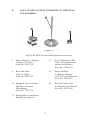
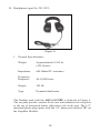
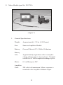
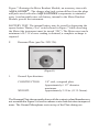
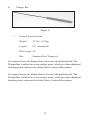
AQUA-SCOPE
User Manual
®
Proprietary Notice
The contents of this manual are proprietary to Heath Consultants
Incorporated. Reproduction of this manual, in whole or in part, is
prohibited without the express written consent of Heath Consultants
Incorporated.
Heath Consultants Incorporated operates under a continual product
improvement program and reserves the right to make improvements
and/or changes without prior notification.
This manual supersedes all previous manuals for the Heath AquaScope.
HPN 2913769
Revision B
©COPYRIGHT 2001, Heath Consultants Incorporated
AQUA-SCOPE®
User Manual
Heath Consultants Incorporated
Houston, TX
713-844-1300
Fax: 713-844-1309
1-800-HEATH-US
www.heathus.com
Heath....Safety, Leadership, Innovation, Performance
Then, Now and Tomorrow
INTRODUCTION
Economy and hygiene demand the most expedient way to locate and
repair water pipeline damage. More extensive water leaks can also
result in considerable danger to traffic by causing street flooding.
The best method to locate and pinpoint leaks in water pipelines is
by means of electro-acoustical detection. The sounds made by water
escaping from a water leak spread as spherical background waves in
the ground. The sounds are also transmitted by the (metallic) pipeline
itself. The use of suitable detecting devices enables us to determine the
exact location of a leak by listening to the escaping water from a small
hole in the water pipeline. The sounds made from such leaks provide
a good condition for electro-acoustical water leak detection.
FUNCTION
The Heath Consultants Incorporated AQUA-SCOPE® System is
an advanced state-of-the-art electro-acoustical water leak locator
designed to provide the operator with the means for efficient locating
and pinpointing of water pipeline leaks.
The instrument amplifier/receiver unit provides a wide range of clarity,
simplicity, and ease of control. The ground and hand microphones
have good wind immunity for outdoor use. A removable handle and
extension rods are handy for compact storage.
1
TABLE OF CONTENTS
INTRODUCTION...........................................................................1
FUNCTION ........................................................................................1
TABLE OF CONTENTS .....................................................................2
CHAPTER I
I.
AQUA-SCOPE SYSTEM, COMPLETE:
AQUA-SCOPE Basic System (Figure 1) ..................................4
II.
AQUA-SCOPE SYSTEM, COMPLETE W/OPTIONAL ACCESSORIES:
AQUA-SCOPE System with Optional
Accessories (Figure 2) .............................................................5
III.
A.
B.
C.
D.
E.
F.
G.
Amplifier Module (Figure 3) ........................................6
Ground Microphone (Figure 4) .....................................7
Direct Contact Microphone (Figure 5)............................9
Headphones (Figure 6) ...............................................10
Meter Module (Figure 7) .............................................11
Resonant Plate (Figure 8) ............................................12
Plunger Bar (Figure 9) ................................................13
CHAPTER TWO
PRINCIPLES OF SOUND:
A.
Engineering References ............................................14
B.
Relating Sound Principles
to Leakage Detection .................................................17
2
CHAPTER THREE
IV.AQUA-SCOPE OPERATION:
A.
Application ................................................................ 19
B.
Leakage Detection with the
Direct Contact Microphone ......................................... 19
C.
Pinpointing with the Ground Microphone .................... 22
D.
Exercises with the Direct
Contact/Ground Microphones .................................... 25
E.
Graphical and Numerical Determination
of the Point of Leakage ........................................... 26
F.
Practical Examples ............................................... 29
G.
Alternate Methods of Leakage Detection ..................... 31
CHAPTER FOUR
V.
SERVICE INFORMATION:
A.
Warranty and Warranty Repair .................................... 33
Customer Assistance, Manufacturing and
Service Locations ....................................................Back Cover
3
CHAPTER ONE
I.
AQUA-SCOPE SYSTEM, COMPLETE:
7
4
3
5
1
5
6
2
(Figure 1)
AQUA-SCOPE Basic System (part No. 2903768)
1. Direct Contact
Microphone w/ext
(Part No. 2916428)
5. Ground Microphone
w/Handle
(Part No. 2916427)
2. Amplifier Module
6. Microphone Cables (2)
(Part No. 2916426) (Part No. 2916411)
3. Headphones 7. Carrying Case
(Part No. 2911352) (Part No. 2913767)
4. Instruction Manual
(Part No. 2913769)
4
II.
AQUA-SCOPE SYSTEM, COMPLETE W/ OPTIONAL
ACCESSORIES:
9
8
10
(Figure 2)
AQUA-SCOPE System with Optional Accessories
8. Meter Module w/ Battery
12.
Charger (110 VAC)
(Part No. 2923754)
Good Vibrations VHS
Video Training Presenttation (Not Shown)
(Part No. 7106653)
9. Resonant Plate 13.
with 18” Spike
(Part No. 2921326)
Meter Module
w/ Battery Charger
(220 VAC) (Not Shown)
(Part No. 2923698)
10.
Magnetic Tip used with 14. Ear Pad Cover used
The Direct Contact w/ Headset (Not Shown)
Microphone(Part No. 2927414)
(Part No. 2923776)
11. Plunger Bar w/ Insulated
Handle (Not Shown)
5
A. Amplifier Module (Part No. 2916426)
(Figure 3)
1. General Specifications:
Weight:1.37 lbs. (620 grams) including batteries.
Size:
5” deep x 3.7” wide x .4” thick (12.7 x 9.40 x 6.096 cm) including all projecting knobs, clips, and jacks.
Batteries:
Requires 2 alkaline 9-volt batteries. Eveready 522, Mallory MN1604 or any NEDA 1604A type is recommended.
Battery Life: Approximately 30 hours.
Amplifier
Gain:
Approximately 3 x 10⁵ volts/volt maximum.
Storage
Temperature: Limited to the specifications on the batteries used.
Figure 3 depicts in two views the Amplifier Module with all hardware,
in put/output jacks, and controls. Battery access is gained by removing
the Battery Access Plate, exposing the two nine volt batteries, which
power the instrument. The battery adjacent to the input jack should
be removed first. The second battery may require lateral movement
toward the input jack end to clear the opening. Replacement and insertion should be performed in the opposite sequence. Be careful not to
cross thread the access plate retaining screw when securing the battery
access plate.
6
The push button “LISTEN” control switch should only be depressed
after the ground microphone has been firmly placed on a solid surface
and one to two seconds Sensor Settle Time elapsed. When using the
direct contact microphone, be certain that the tip is in firm contact with
the pipe, valve box, etc., before depressing the “LISTEN” control
switch.
B.
Ground Microphone (Part No. 2916427)
(Figure 4)
1.
General Specifications:
Construction: Acoustically suspended variable
reluctance sensor
Impedance:
380 Ohm DC resistance
Frequency
Response:
10 - 300 Hertz
Weight:
Approximately 2 Lbs. 5 Oz.
(1049 grams)
7
Figure 4 illustrates the Ground Microphone with the Ground Microphone
Handle. The shock insulator minimizes sound coupling through the handle.
The foam rubber sound seal restricts ambient noises, which may be present in the work area. The internal sensor is suspended and magnetically
shielded to improve the signal to background noise ratio. The 1/4” plug
mates with the 1/4” jack labeled “M” on the Amplifier Module via one of
the two Microphone Cables.
8
C. Direct Contact Microphone (Part No. 2916428)
(Figure 5)
1. General Specifications:
Construction: Cold rolled steel case. Stainless steel sensor shaft, probe tip, and extension rods. Rods are 5/16” diameter. All threaded sections are #10-32 thread. Poured in place, the urethane core suspends the sensor shaft in the body for acoustical isolation. Each Direct Contact extension is 24” long.
Sensor:
Frequency
Response: Piezo-Ceramic, resonant at approximately 3000 Hz.
Approximately 300-6000 Hertz.
The Direct Contact Microphone, microphone tip, optional magnet,
and two extensions are depicted in Figure 5. All threaded joints are
stainless steel on the Direct Contact Microphone; probe tip, and the
extensions. The 1/4” plug mates with the 1/4” jack labeled “M” on
the Amplifier Module via one of the two Microphone Cables.
9
D. Headphones (part No. 2911352)
(Figure 6)
1. General Specifications:
Weight:
Approximately 0.94 Lbs
(425 Grams)
Impedance: 600 Ohms DC resistance
Frequency
Response:
40-18,000 hertz
Output:
105 db
Type: Dynamic/dual/mono
The Headset used with the AQUA-SCOPE is depicted in Figure 6.
The ear pads provide comfort to the user and minimize the reception
at the ear of unwanted noises adjacent to the work area. The 1/4”
monaural phone plug mates with the 1/4” phone jack labeled “H” on
the Amplifier Module.
10
E. Meter Module (part No. 2923754)
(Figure 7)
1. General Specifications:
Weight:
Approximately 1.2 Lbs. (545 Grams)
Size: Same as Amplifier Module
Battery:
General Electric GC-9 Nickel Cadmium
Battery
Life: Approximately eight hours after a complete charge. Charge time is sixteen hours. Nominal overall life is 1000 complete discharge cycles.
0-1 milliamp ere D.C.
Meter:
Amplifier
Gain:
200 volts/volt maximum. Meter response is matched to the Amplifier Module output.
11
Figure 7 illustrates the Meter Readout Module, an accessory item with
AQUA-SCOPE® . The charger plug/jack system differs from the plugs
and jacks used with other AQUA-SCOPE® components to minimize
error. A rechargeable nine-volt battery, internal to the Meter Readout
Module, powers the instrument.
BATTERY TEST: The internal battery may be tested by depressing the
square button “Battery Test” switch shown in Figure 7 while observing
the Meter (the instrument must be turned “ON”). The Meter must read a
minimum of 0.7. If a lower reading is obtained, a complete recharge is
required.
F.
Resonant Plate (part No. 2921326).
(Figure8)
1.
General Specifications:
CONSTRUCTION:
1/8” steel, octagonal plate.
Approximately 6 1/2” diameter maximum.
WEIGHT:
Approximately 2.5 Lbs. (1135 Grams).
The Resonant Plate shown upside down with the contact rod and thumbscrews
not assembled in Figure 8 is used to enhance water leak detection in unpaved
areas. The Ground Microphone rests on top of the Plate during use.
12
G.
Plunger Bar
(Figure 9)
1.
General Specifications:
Weight:
13 Lbs. (5.9 Kg)
Length:
62” (assembled)
Bar Length: 40”
Bar: Standard Steel Tempered
For unpaved areas the Plunger Bar is driven to the depth desired. The
Plunger Bar is utilized as a sub-surface probe, which provides additional
listening points when used with the Direct Contact Microphone.
For unpaved areas the Plunger Bar is driven to the depth desired. The
Plunger Bar is utilized as a sub-surface probe, which provides additional
listening points when used with the Direct Contact Microphone.
13
CHAPTER TWO
III.PRINCIPLES OF SOUND:
A. Engineering References
This section will cover the basic physics of sound. Section B will
attempt to relate a few of these principles to the field of underground
leak detection and pinpointing.
Wave motion, of which sound is but one example, is classically
regarded as either transverse or longitudinal. In transverse wave
propagation the wave travels perpendicular to the motion of the
source (a plucked string is an example). Longitudinal waves
progress along the axis or body of the media (listening for a train
on its tracks is an example).
The audible limits of sound frequency for people are approximately
from 20 to 20,000 hertz. The human ear responds to sound pressures
from 0.0002 to 2000 dynes/cm (seven orders of magnitude). Sound
intensity is generally expressed on a logarithmic scale (Decibels,
or dB) with the reference intensity taken to be 10-16 watt/cm, so
that:
INTENSITY LEVEL IN DECIBELS = 10 log
In addition the sound pressure (with the reference pressure taken as 0.0002 dyne/cm) is given by:
SOUND PRESSURE LEVEL IN DECIBELS = 20 log
An upper limit exists for this sound pressure depending on the media
involved. For air the upper limit is approximately 191 dB. At this level
rarefaction of the wave causes cavitations and the wave breaks down since
the media can no longer support it. The pain threshold for audible sound is
at an intensity level of 120 Decibels.
14
The Transmission Velocity of Sound in an extended solid is given by:
VELOCITY Longitudinal = Where: EB = The Bulk Modulus (Rigidity) of the Solid
ES = The Shear Modulus (Resistance to Deformation) of the Solid
ρ = Density
In the case of a transverse wave in an extended solid, the Velocity is
determined by the Shear Modulus alone and is expressed as:
VELOCITY Transverse =
If we now divide the Longitudinal Velocity by the Transverse Velocity in
an extended solid, we note that:
Or that the Longitudinal Velocity always exceeds the Transverse
Velocity. This fact is used in Seismology to determine the point or origin
of earthquakes.
Since a fluid cannot sustain a shear (ES = O), no Transverse Wave can be
transmitted in a fluid and the Longitudinal Velocity is given by:
Where: EB is the Adiabatic Bulk Modulus.
15
The Velocity of Sound is given by:
Where: V = Velocity
γ =
R =
T =
m =
the ratio of the specific heat at constant pressure to the specific heat at constant volume.
the universal gas constant.
Absolute Temperature (degrees Kelvin).
Gram Molecular Weight of the gas.
Therefore, the Velocity of Sound in Air is:
Velocity = 331
(At 68° F the velocity = 1125 ft./sec.).
The resonant frequency of rods, plates, pipes, strings, etc. is a function of
the shape, density, elastic properties, and boundary conditions defining
the object(s). In the case of a string, the fundamental resonant frequency
is proportional to the Transverse Velocity and inversely proportional to
length.
Sound dissipation along a fixed length of rod or pipe will be effected by
transit time, constraining forces along the wall perimeter, and the media
in the pipe. Discontinuities may drastically reduce sound transmission.
Point source sound propagating in a spherical pattern dissipates (with no
consideration of losses due to absorption reflection or interference) in sound
pressure per unit area as the square of distance. This means a pressure
decrease of 12 decibels each time the distance traveled doubles.
Sound waves, like other forms of energy, experience reflection and refraction at the boundary between two media. Interference can occur when
two waves from the same source travel different path lengths and reunite.
16
Absorption of sound by materials is a science in itself. Terms often
stated by acoustical wall manufacturers are seal and absorption loss.
Seal refers to sweep strips used on doors to attenuate the transmission
of higher frequencies. Absorption loss or door rating in decibels tends to
increase as the number of laminates (metal, wood, fabric, etc.) increases.
The higher frequencies are attenuated more dramatically than low
frequencies. Sheet lead is often used to reduce plenum crossover.
Finally, the effect of paved surfaces on sound pick-up should be
discussed. For lack of a better name, let us call it the Diaphragm Effect.
Because of the large area and low modulus, the resonant frequency will
be low. This surface, therefore, tends to amplify noises of low frequency
occurring in the soil beneath the paved area and helps immeasurably
in water leak location.
B. Relating Sound Principles to Leakage Detection
The detection and location of underground leaks is implemented by a
variety of instruments and numerous methods. For the purpose of this
section, we will discuss the use of the AQUA-SCOPE and some of
the general conclusions we might draw from the previous section in
that regard.
The Direct Contact Microphone is generally placed against the surface of
a pipe in a position nearly perpendicular to the pipe direction. The sensor
responds to vibration along the axis of the Direct Contact Microphone.
Therefore, the instrument is most sensitive to transverse sound waves
on the pipe. Likewise, sound induced by leaks will be oriented more
likely in a transverse mode. Now no sound can be transmitted through
the fluid or gas in the pipe in a transverse mode based on the previous
section. This means that the pipe wall must carry any transverse sound
transmission alone.
17
The frequency and velocity of the sound induced on the pipe by a
leak will be a function of pipe size, thickness, material and boundary
conditions. Quite important is the rigidity of the pipe. Metal pipe has
a high modulus. Therefore, we will hear the characteristically higher
frequency “pipe” noise generated by a leak. Also, the velocity will be
high or the transit time is short and minimum attenuation of the sound
will result. Plastic pipe has a much lower modulus and, for similar
conditions of pipe size and boundary conditions, the frequency will be
lower with much higher transit time (attenuation).
Other sounds may also be generated by restrictions within the system,
such as: a partially closed valve, a reduction coupler, a booster pump,
etc. These devices will cause turbulence along the pipe wall and will
emit a detectable sound similar to that of a leak. Do not be mislead
by this effect. If these sounds are of sufficient magnitude, you may be
incapable of distinguishing the existence of a leak in the immediate
vicinity.
Soil is basically a non-homogeneous material. Generally the soil will
be layered except directly over man-implanted objects such as pipe.
Fluidic type soils such as clay can create special problems. Any soil
which has a rubber like consistency will greatly attenuate sound.
The actual contact area of the Ground Microphone with a surface is
quite small. If a hard surface (even frozen earth will help) is unavailable,
the use of a resonant plate may help. Any solid structure penetrating or
covering the earth can be used to advantage.
Sound may be induced on a pipe by secondary noises such as leaking
water filling a cavity. Once the cavity fills this source of noise
vanishes.
18
CHAPTER THREE
IV. AQUA-SCOPE USER’S GUIDE:
A.Application
The pinpointing of unknown water leakage can be accomplished
by the use of a combination of components, which make up the
kit. By using different microphones and by amplification with
a solid-state receiver, the sounds of water leaking from the line
can be localized and pinpointed. The type or pitch of the sound
varies from the deep roaring of a main up to a very high whining
of leaking valve packing. It is necessary to differentiate these
sounds from the other normal background noises.
Auxiliary Means - Plunger Bar: Useful when searching for leaks
on soil or sod covered pipes. Surfaces of this nature are poor
sound transmitters and require the use of a bar as an auxiliary
sounding.
Resonant Plate: The Resonant Plate is a specially machined
plate, which improves the sounding qualities. The Plate is
designed to accept the Ground Microphone.
B.
Leakage Detection with the Direct Contact Microphone
Preliminary Detection with the Direct Contact Microphone:
The Direct Contact Microphone is used for preliminary detection
in direct contact with an accessible part of the main, hydrant,
curb valves, or directly on the service in the house, etc. The
intensity of this direct contact is always in direct relationship
to the distance of the leak from the point of measurement and
indicates where the leak might be. By acoustic comparison of
the noise heard in the Headset and by visual observation of
the noise strength with the aid of the optional meter readout
module at one or more points of measurement, the leak can be
approximately located.
19
(Figure 10)
As you can see from Figure 10, in preliminary detection the Direct Contact
Microphone is connected with the Amplifier Module and the Headset is
plugged into the jack on the Amplifier Module. The Volume is then turned
clockwise and the amplification is turned up enough so that the sound
of a leak is recognizable. The position of 4 to 6 on the volume control is
recommended for best sound intensity.
Procedure of Preliminary Detection: The point of the Direct Contact
Microphone is placed on the part of the line, which is to be checked. The
point should be abraded and firmly held against the line to insure good
contact. When the Direct Contact Microphone is firmly placed on the line,
the “Listen” control switch on the Amplifier Module is depressed. This will
complete the electrical contact between the microphone and the amplifier.
The switch should not be depressed before or while making contact, as
the noise of making contact is unpleasant to the ear. Tests are made in this
manner and sound levels for the tests compared (see Figure 11). Figure
12 is an example of the above technique in a field situation. The Direct
Contact Microphone should not be immersed in water. If a test must be
taken in deep water, use the extensions or contact the line or desired test
point with a rod or key. The tip of the Direct Contact Microphone is then
used on the rod or key.
20
SOUND LEVEL INTENSITY AT DIFFERENT TEST POINTS
(Figure 11)
Example of a Preliminary Detection (Figure 12): After opening valve boxes
on the main at 1, 2 and 3, the valve stems are checked with the Direct
Contact Microphone. At all three valves a small noise is recognized. The
noise at valve 2 is a little bit louder but it is not enough louder to determine
a difference in the intensity of sound. To decide the further direction of
examination, take comparative measurements at curb valve 4, at hydrant
9 and at curb valve 10. While the noise at point 4 is louder, no noise is
heard at point 9 and 10. The search is continued in the direction of point 4.
Further listening at points 5 and 6 shows a small increase of intensity of
sound and a slight decrease at point 7.
(Figure 12)
21
At point 7 there is no curb valve present nor is there any accessible
contact point on the service to the house. Therefore, a direct contact
inside the house is necessary. At hydrant 8 the noise is also very much
smaller. This acoustical preliminary detection can be accomplished
with far more ease by using the meter on the optional Meter Readout
Module. At this time by listening to the loudest noise that has been
detected, a medium reading of the scale is to be set. In this example,
at measurement point 5, a reading of .60 units is set on the scale by
turning the Meter Readout Control Knob clockwise while a test is being
taken. This setting is recommended to be able to see an increase or a
decrease of the reading on the instrument at the different test points. For
all further comparative measurements, the setting of intensity of sound
and meter are not to be changed, as any change during comparisons will
affect the uniformity of the test. If a change in setting is necessary, all
comparative tests must be repeated at the new setting. Meter reading
at point 4 gives a decrease of reading down to .15 units, which would
substantiate the acoustical result. On the other hand, the meter reading
at point 6 shows an increase to nearly .70 units. This indicates further
search towards point 7 is necessary. The test in house 7 is conducted
with an unchanged setting of the instrument. It gives another decrease
in instrument reading of .30 units. But we are to keep in mind that the
length of the service (the test was taken in the house) might influence
the result of the test. The final measurement at hydrant 8 is less than .10
units. Following this preliminary detection, the leakage should be near
point 6. Pinpointing is now conducted with the Ground Microphone.
C. Pinpointing With The Ground Microphone
The Ground Microphone is exchanged for the Direct Contact
Microphone. The “Listen” Control switch at the upper left of the
instrument is the interface between the Microphone and the Amplifier
and should only be depressed when the Ground Microphone is placed
in a test position. In working with the Ground Microphone, use a setting
of 4 to 6 units of amplification. Using higher sensitivity by opening
the sensitivity (volume) control will also give an amplification of
background noises.
22
SOUND LEVEL INTENSITY AT DIFFERENT TEST POINTS
(Figure 13)
For the pinpointing of the leak, the Ground Microphone will be placed
as exactly as possible over the water main or service with test points a
maximum of 6’ apart. All noises received are to be compared with each
other. The approach to the leak will be recognized by a higher intensity and
increase of the noise. Above the point of leakage the intensity will reach
a maximum. As you pass the leak the intensity will decrease. The meter
reading will show the same result as the Audio test.
Example of a Pinpointing Situation:
(Figure 14)
In the example of the preliminary detection (Figure 14), a leak near the point
of measurement number 6 was anticipated. For final pinpointing with the
Ground Microphone, the section between points 4 and 7 will be checked at
close intervals (3’ to 6’), and near point 6 you will find a very strong noise.
This is the source of the leakage. When doing such examinations with the
Ground Microphone you should extend the test pattern as the leak may
cause false noises. Some examples from practical use are detailed later in
this Guide.
23
Influence of the Leak Noise (Material of the Lines):
You should know the material of the line being tested as the sound
transmission of leak sounds vary greatly from cast iron, to steel, to asbestos
cement, and PVC. A simple example to clarify this: If a steel line, suspended
from a cable is struck with a hammer, it will sound like a gong. A plastic or
asbestos cement line would give a thumping noise on impact but it wouldn’t
resonate the sound at all.
Pressure in the Lines: The pressure in the line is also a very important factor.
High pressure normally gives a loud noise, a high frequency, and good sound
characteristics for localization. It generally can be said that a pressure of
twenty pounds per square inch (PSI) is sufficient enough to locate leaks.
Under twenty PSI it may be necessary to use auxiliary means.
Special Circumstances Encountered: The conditions of the cover over
the main will especially influence the detection of the leak noise. A very
hard ground has a better efficiency for sound transmission and is of higher
resonance than muddy ground or sod. Sand and compact sand and stony
grounds are very efficient sound transmitters.
On the other hand, the transmittance of sound under frozen ground may be
so excellent that it is very difficult to locate the maximum (Loudest Point)
since a large section of the frozen earth will be vibrating.
Surface: The surface in the environment can greatly influence the detection.
It is necessary when pinpointing to consider the surface on which the Ground
Microphone is placed. A change in the kind of surface (from sod to asphalt,
for example) from one medium to the other may cause a very contradictory
test value. This can sometimes cause so many differences of noise that a
real comparison of noises for the leak detection may be difficult.
Time of Work: The choice of day or night testing is very dependent on the
local situation. In rural or residential areas work during the day is possible.
In areas with heavy traffic noise, loud machines, and/or factories, work
during evening or night hours may be necessary.
24
D. Exercises with the Direct Contact/Ground Microphone
Initially it is necessary to become acquainted with the background noise
of the instrument under different positions of intensity.
Beyond positions 6 and 7, the Amplifier noise is easily heard. To have
some idea about the efficiency of amplification, the Direct Contact
Microphone should be tried with different positions of intensity while
in contact with a mechanical type watch. Due to the high amplification,
the sound of the watch, which is normally not heard, is as audible as
the noise of a small leak.
The third exercise is the amplification of a typical noise of water usage.
This is especially true on metallic lines. For this purpose a Direct
Contact Microphone will be (with the position of Volume set from 4
to 6) placed in contact with a curb valve and one of the faucets in the
house and also some faucets of houses in the neighborhood opened.
Open and close each of these outlets in the sequence of several seconds.
Exercises on different types of pipe material will give some idea on
transmission of sound.
Exercises with the Ground Microphone: Listening to background sounds
using various sensitivities is necessary. For example, check to hear the
sound of a walking pedestrian. Become acquainted with the change of
background noise when you are placing the Ground Microphone over
different surfaces, such as pavement, sod, or other types of surfaces.
With the Ground Microphone directly at the curb wall over a service
line valve, water flowing through the service might be heard. Opening
and closing the outlet also is recommended as an exercise.
Type of Leak and Different Types of Leak Noises: The experienced listener
will know from the type of noise which type of leak is present, the distance
of the leakage location, and also the type and amount of leakage. Small holes,
especially in steel lines under high pressure, will give very high frequency
sounds. A total breakdown of the line with a large amount of water leaving
the line will produce a typically deep roaring sound.
25
If you are inspecting an intersection with several valves, these results
may be predicted:
1. Using the Direct Contact Microphone at point 3, a leaking valve
packing will give a very high pitched sound. Using the same amplifier
intensity at points 1, 2, and 4, will result in much lower sound
readings on the meter.
(Figure 15)
2. A total break of the line at point 3 will give nearly similar values on
the meter at all four test points. However, a slight increase at point
3 will indicate the direction for further search.
E.Graphical and Numerical Determination of the Point of Leakage
The reading of the exact measurement of sound intensity with the
instrument allows the graphical or the numerical determination of the
location of the leak. The procedure, therefore, is controlled measurement
with the Direct Contact Microphone at two points on the same line at two
valves, two hydrants, two curb valves, or at two direct contacts if the line
is exposed. For these measurements it is recommended to use the optional
Magnet Attachment, which will provide uniform contact and will give
very constant values. It is necessary to observe the sound over a period
of time to determine an average value it the reading is changing. For this
method we assume that the product of sound intensity and distance is
a constant. Therefore, for two points A and B and distance XA and XB
from a leak: IA XA = IB XB
Where: IA and IB are the values for intensity at points A and B
respectively, and the total distance between test points is:
XA + XB = X
26
This gives two simultaneous equations:
IA XA - IB XB = O
XA + XB = X
O
-IB
X 1
IBX
XA = ———— = ——————
IA -IB IA + IB
1 1
AO
XB =
1X
IAX
———— = ———————
IA -IB
IA + IB
1
1
Example: Making contact measurements using the Magnet Attachment, we
check two hydrants separated by a distance of 70 yards. At hydrant A we
read .30 units and at hydrant B we read .90 units. We plot this graphically
by first laying off the X-axis as the total distance between hydrants, or
70 yards. We now mark off the value of intensity for hydrant A along the
positive Y-axis. LABEL THIS POINT B. At distance X from the origin,
draw a perpendicular. Starting at X and moving in the negative Y direction,
lay off the value of intensity for hydrant B. LABEL THIS POINT A. Draw
a straight line from point B to point A. Where this line intersects the X axis
is the point of leakage. Note the inversion of points A and B.
27
By the numerical technique the distance from test point A to the leak is:
XA = ( .9 ) x 70 Yards = 52.5 Yards
.9 + .3
XB =
(
Similarly:
.3
.9 + .3
)
x 70 Yards = 17.5 Yards
(Figure 16)
The graphical as well as the numerical solution are only preliminary
determinations. The ideal case of two equal contact measurements
is so remote, that a check with the Ground Microphone is always
recommended.
28
F.
Practical Examples
Test probe measurement at valve 1 is .40 units; at valve 2, .90 units;
at valve 3, .10 units, and at hydrant 4, zero units. This indicates the
leak should be between points 1 and 2. Using the Ground Microphone,
point 5 is the strongest test. A sewer is present at point 5. This noise
could be the sound of water flowing in the sewer. If this is the case,
tests at 6, 7, and 8, the other sides of the sewer, the same intensity of
sound should be found. The comparatives show at point 5, .60 units
and the other points (6, 7, and 8), a decrease. This confirms the leak
is at point 5. The combination of the acoustical and numerical tests is
conclusive in this instance.
(Figure 17)
Houses without curb valves in a leakage area should be tested with
the Direct Contact Microphone directly on the service line in the
basement.
Checking with the Ground Microphone at point 2 gives a very strong
test. At point 1 a weak test is noted. The leak is at point 1. This is caused
by surface proximity and increased pipe turbulence sound at a bend
in the pipe. It is necessary to know the location of bends, as they will
cause an error in pinpointing if they are not taken into consideration.
Difference in pipe location will influence the measurement. In case of
doubt, drawings of local situations or a pipe locator should be used.
29
(Figure 18)
The noise of the leak should be checked with the Direct Contact Microphone
at hydrant 4 and at valve 6. Pinpointing with the Ground Microphone will
give a strong noise at point 5. However, at bend points 1, 2, and 3 a high
level of sound may be found.
Please note the effect: Different depths in the cover over the main can give
a varying intensity of the sound. It is always recommended to extend test
areas and not dig at the first strong noise.
(Figure 19)
A restriction or a reducer in the line or a partially closed valve may cause
a false leakage indication. Such cases seldom occur, but you never can
exclude them. Such noises should be checked very carefully and then the
restricted parts of the line should be eliminated if possible.
In checking the main, a leak noise is found at point 1. The next test of the
house connection results in a strong noise at 2. But here a steeply sloped
drain for wastewater is running. To eliminate this condition, the Ground
Microphone is placed at 3 and 4. If the noise at 2, 3, and 4 yield the same
instrument reading, it must be assumed that the drain is causing the sound
and the leakage is at point 1.
30
(Figure 20)
Leakage on Asbestos-Cement and Plastic Pipe
The very poor transmission of sound on this material will make other
methods for detection necessary. The efficiency of using the Direct Contact
Microphone for the preliminary localization will be diminished by the lack
of sound transmission through the line. Also, if testing fittings with direct
contact with the Direct Contact Microphone no sound of flowing water is
heard, the presence of a leak cannot be excluded. It is recommended in all
cases to check over the mains with the Ground Microphone at distances
of 3 to 6 feet.
Other Sonics
Some highly sophisticated sonic instrumentation has been developed using
sound delay techniques, computer analysis, and analysis of sound waves
on the oscilloscope. These methods are quite expensive but should be
considered where conventional sonic methods are impractical.
G.
Alternate Methods of Leakage Detection
Tracer Gases
For situations where sonic testing is completely impractical, the use
of tracer gases should be considered. There are several tracer gas
systems available and the following is a brief synopsis of advantages
and disadvantages of four of these systems:
31
1. Nitrous Oxide with Infrared Detection: One of the advantages of
nitrous oxide is that it is water soluble and the line does not have
to be dewatered prior to the test. The infrared detector is very
specific for nitrous oxide so that there is no need to worry about
interfering gases. One of the real disadvantages of this system is
that nitrous oxide is heavier than air so that holes must be probed
to approximately the depth of the main. Two other disadvantages
are that heavier than air gases are more difficult to pinpoint than
lighter than air gases, and the infrared detection equipment is
very expensive.
2. 10% Helium/90% Air: With this system, the line must be dewatered
before the helium/air mixture is inserted. Helium has the advantage
of being an extremely small molecule and very light. Detection is
by Thermal Conductivity or Comparative Sonics.
3. Methane/Nitrogen: A mixture of 2 1/2% methane balance nitrogen,
utilizing flame-ionization as the detector, is an extremely effective
method. Methane, being lighter than air, requires no test hole
placement. However, the line does have to be dewatered.
4. Flame-ionization detection of methane is in the low parts per
million ranges, so that even small amounts of methane are readily
detectable.
5. Methane/Argon: This mixture takes advantage of both a heavier
and a lighter than air gas with the methane being detected by
flame-ionization and the argon acting as a confirming gas being
detected by comparative sonics. The helium and methane tracers
require a pre-survey of the area before insertion of the tracer.
They can all be interfered with by natural gas leaks or naturally
occurring methane.
Tracer Gas Surveys are extremely expensive compared to Sonic
Surveys and should only be considered when sonics are completely
impractical.
32
CHAPTER FOUR
V. SERVICE INFORMATION:
A. Warranties and Warranty Repair
All instruments and products manufactured by the Heath
Consultants Incorporated are warranted to be free from defects
in material and workmanship for one (1) year from the date of
shipment.
Furthermore, the warranty on authorized repairs in Houston FSC
and regions is ninety (90) days materials and thirty (30) days
labor. This repair warranty does not extend any other applicable
warranties.
Our warranty covers only failures due to defects in materials
or workmanship, which occur during normal use. It does not
cover failure due to damage which occurs in shipment, unless
due to improper packing, or failures which result from accident,
misuse, abuse, neglect, mishandling, misapplication, alteration,
modification or service by anyone other than a Heath warranty
repair location.
Battery and damage from battery leakage and all expendable items
such as filters and Plunger Bar rods are excluded from this warranty.
Also, O-rings, gaskets and seals for the Petro-Tite product line are
excluded from warranty coverage. In addition “wetted” parts in
various Petro-Tite products are warranted for 30 days only.
Heath’s responsibility is expressly limited to repair or replacement
of any defective part, provided the product is returned to an
authorized warranty repair location, shipping charges pre-paid and
adequately insured. Return shipping charges and insurance will be
paid by Heath warranty expense.
We do not assume liability for indirect or consequential damage
or loss of any nature in connection with the use of any Heath
product.
33
There are no other warranties expressed, implied or written except
as listed above.
The following suggestions will expedite the repair of your
instrument:
Package carefully, using the original shipping carton, if available, return all components.
Specify your complete shipping and billing addresses.
Specify the instrument or product name, model number and serial numbers on all correspondence.
Include a brief description of the problem you are experiencing and specify person to be contacted for information.
34
CUSTOMER ASSISTANCE, MANUFACTURING AND SERVICE
LOCATIONS
CORPORATE HEADQUARTERS
Heath Consultants Incorporated
9030 Monroe Road
Houston, Texas 77061
Phone: (713) 844-1300
Fax: (713) 844-1309
MANUFACTURING AND WARRANTY SERVICE CENTERS
Heath Consultants Factory Service Center
9030 Monroe Road
Houston, Texas 77061
Phone: (713) 844-1350
Fax: (713) 844-1398
DIVISION OFFICES
Northeast Region
1051 Garden Street
Greensburg, PA 15601
Phone: (724) 836-7830
Fax: (724) 836-7835
Central Region
9030 Monroe Road
Houston, Texas 77061
Phone: (713) 844-1300
Fax: (713) 844-1309
Southeast Region
1645 Murfreesboro Road, Suite E
Nashville, TN 37217
Phone: (615) 361-8306
Fax: (615) 361-8651
Western Region
4100 S. Fremont Avenue, Suite 150
Tucson, AZ 85714
Phone: (520) 790-4971
Fax: (520) 790-5016
Heath Consultants Incorporated operates under a continual product improvement program
and reserves the right to make improvements and/or changes without prior notification.
Heath Consultants Incorporated
Houston, TX
713-844-1300
Fax: 713-844-1309
1-800-HEATH-US
www.heathus.com
Heath...Safety, Leadership, Innovation, Performance
Then, Now and Tomorrow