1
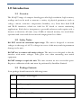
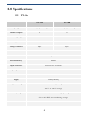
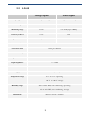
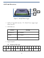
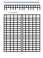
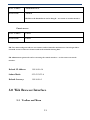
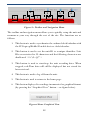
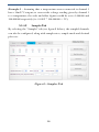
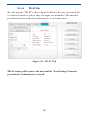
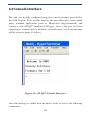
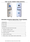
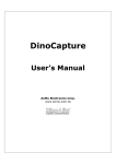
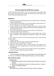
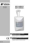
InteliSen Limited
Electronics & Software Services
iDAQ™ Data-Logger
User’s Guide
Copyright ©2012 InteliSen Limited. All rights reserved.
Contents
1.0
Introduction .............................................................................................. 3
1.1
Overview ............................................................................................... 3
1.2
Safety Notice ......................................................................................... 3
1.3
Package Contents .................................................................................. 3
2.0
Specifications ............................................................................................ 4
2.1
UV-0x.................................................................................................... 4
2.2
AD-08 .................................................................................................... 5
2.3
CU-0x .................................................................................................... 6
2.4
PT-0x .................................................................................................... 7
3.0
Unit Overview ........................................................................................... 8
3.1
4.0
Connector Pin-outs................................................................................ 8
Making a Connection ............................................................................... 10
4.1
5.0
Default Settings .................................................................................. 10
Web Browser Interface............................................................................ 11
5.1
6.0
Toolbar and Menu ............................................................................... 11
5.1.1
Graphical Interface ..................................................................... 13
5.1.2
Real-Time Channel Status .......................................................... 14
5.1.3
Download Page ........................................................................... 14
5.1.4
SettingsPage ............................................................................... 15
Console Interface ..................................................................................... 19
2
1.0 Introduction
1.1 Overview
The iDAQ™ range of compact data-loggers offer high resolution, high accuracy
readings and can be used to measure a variety of physical parameters (such as
voltage, current, resistance, temperature, humidity, etc). Units have both USB
and Wi-Fi interfaces, which are ideal for PC based or remote monitoring
applications. Each device incorporates a powerful webserver and requires only a
browser to function; all units carry 256Kb of internal memory for stand-alone
operation and can record data at intevals ranging from 5s to 24hrs.
1.2 Safety Notice
DO NOT exceed the maximum input range. The unit is designed to measure
voltages in the range of ±2.5V; voltages in excess of this may result in permanent
damage to the unit.
DO NOT use in contact with mains voltages. The unit is not designed to directly
interface with mains voltages. Take great care when measuring near mains
equipment.
DO NOT attempt to repair the unit. The unit contains no user serviceable parts.
Repair or calibration of the unit must be performed by InteliSen Limited.
1.3 Package Contents
Your package should contain the following items:
1.
1 x iDAQ™ Data-logger
2.
1 x USB cable
3.
1 x Power supply
4.
8 x 4-Way terminal block
5.
1 x User‟s guide (CD)
3
2.0 Specifications
2.1 UV-0x
UV-04
UV-08
Input type
General purpose voltage
General purpose voltage
Number of inputs
4
8
Measuring range
±2.5V
±2.5V
Accuracy at 25 ºC
0.1%
0.1%
Voltage resolution
10µV
10µV
Converter resolution
22 bits
Conversion time
72ms per channel
Internal Memory
256Kb
Input connectors
3.5mm Screw terminals
Input impedance
>> 1 MΩ
Interface
USB 2.0 and Wi-Fi
Supply
5VDC (100mA)
Temperature range
0 ºC to 70 ºC operating
-20 ºC to +80 ºC storage
Humidity range
20% to 90% RH, non-condensing, operating
5% to 95% RH, non-condensing, storage
Dimensions
92mm x 51mm x 18.3mm
4
2.2 AD-08
Voltage Inputs
Pulse Inputs
Input type
General Purpose Voltage
Voltage-Free Pulse Input
Number of inputs
4
4
Measuring range
±2.5V
0 to 2^24 (upto 1KHz)
Accuracy at 25 ºC
0.1%
N/A
Input Resolution
10µV
N/A
Converter resolution
22 bits
Conversion time
72ms per channel
Internal Memory
256Kb
Input connectors
3.5mm Screw terminals
Input impedance
>> 1 MΩ
Interface
USB 2.0 and Wi-Fi
Supply
5VDC (100mA)
Temperature range
0 ºC to 70 ºC operating
-20 ºC to +80 ºC storage
Humidity range
20% to 90% RH, non-condensing, operating
5% to 95% RH, non-condensing, storage
Dimensions
92mm x 51mm x 18.3mm
5
2.3 CU-0x
CU-04
CU-08
Input type
Number of inputs
4-20mA
4
8
Measuring range
±1A
Accuracy at 25 ºC
1%
Input Resolution
10µA
Converter resolution
22 bits
Conversion time
72ms per channel
Internal Memory
256Kb
Input connectors
3.5mm Screw terminals
Input impedance
>> 1 MΩ
Interface
USB 2.0 and Wi-Fi
Supply
5VDC (100mA)
Temperature range
0 ºC to 70 ºC operating
-20 ºC to +80 ºC storage
Humidity range
20% to 90% RH, non-condensing, operating
5% to 95% RH, non-condensing, storage
Dimensions
92mm x 51mm x 18.3mm
6
2.4 PT-0x
PT-04
Input type
Number of inputs
PT-08
PT100 Temperature Sensor
4
8
Measuring range
-200°C to +800°C
Accuracy at 25 ºC
0.01°C
Temperature resolution
0.001°C
Converter resolution
22 bits
Conversion time
100ms per channel
Internal Memory
256Kb
Input connectors
3.5mm Screw terminals
Input impedance
>> 1 MΩ
Interface
USB 2.0 and Wi-Fi
Supply
5VDC (100mA)
Temperature range
0 ºC to 70 ºC operating
-20 ºC to +80 ºC storage
Humidity range
20% to 90% RH, non-condensing, operating
5% to 95% RH, non-condensing, storage
Dimensions
92mm x 51mm x 18.3mm
7
3.0 Unit Overview
1
2
3
Figure.1 – iDAQ™ Data-Logger
1. USB 2.0 Compatible interface / 5V, 100mA Power supply input
(Mini Type-B)
2. LED Indicator
Pattern
Meaning
Flashing (1s)
Unit running
Steady
Unit stopped
Off
No power or critical failure
3. Input channels
3.1 Connector Pin-outs
01
02
03
Ch1
04
05 06 07 08 09 10 11 12 13 14 15 16
Ch2
Ch3
8
Ch4
17 18 19 20 21 22 23 24 25 26 27 28 29 30 31 32
Ch5
Ch6
Ch7
Ch8
3.2 Pin Definitions
Pin
UV04/08
AD08
CU04/08
PT04/08
Pin
UV08
AD08
CU08
PT08
1
X
X
X
IO1+
17
X
X
X
IO5+
2
AN1+
DIG1+
AN1+
AN1+
18
CH5+
AN1+
CH5+
AN5+
3
AN1-
DIG1-
AN1-
AN1-
19
CH5-
AN1-
CH5-
AN5-
4
X
X
X
IO1-
20
X
X
X
IO5-
5
X
X
X
IO2+
21
X
X
X
IO6+
6
AN2+
DIG2+
AN2+
AN2+
22
CH6+
AN2+
CH6+
AN6+
7
AN2-
DIG2-
AN2-
AN2-
23
CH6-
AN2-
CH6-
AN6-
8
X
X
X
IO2-
24
X
X
X
IO6-
9
X
X
X
IO3+
25
X
X
X
IO7+
10
AN3+
DIG3+
AN3+
AN3+
26
CH7+
AN3+
CH7+
AN7+
11
AN3-
DIG3-
AN3-
AN3-
27
CH7-
AN3-
CH7-
AN7-
12
X
X
X
IO3-
28
X
X
X
IO7-
13
X
X
X
IO4+
29
X
X
X
IO8+
14
AN4+
DIG4+
AN4+
AN4+
30
CH8+
AN4+
CH8+
AN8+
15
AN4-
DIG4-
AN4-
AN4-
31
CH8-
AN4-
CH8-
AN8-
16
X
X
X
IO4-
32
X
X
X
IO8-
9
4.0 Making a Connection
To connect to the unit you must first ensure that it is switched on (plugged
in) and in wireless range of your PC/Laptop/Mobile/Portable device. A WiFi scan must be performed (this varies according to the operating system
used) and a manual connection has to be made. Figure.2 below gives an
example.
Figure.2 –Scan for iDAQ™
Once a connection has been made, it will be possible for the user to access
the built-in web server and start to utilise the unit. This is achieved by
launching a web browser and entering the default IP address of
http://192.168.0.10. You will then be prompted for a user name and
password; the default settings are as follows:
4.1 Default Settings
Administrator access
10
User Name:
Administrator
Password:
Admin
NB: This is the default but it can be changed – see section on console interface.
Guest access
User Name:
Guest
Password:
Guest
NB: User names and passwords are case sensitive and are limited to 32 characters. Guest login allows
restricted access to web-server features and can be useful for sharing data.
NB: Administrator passwords can be reset using the console interface – see the section on console
interface.
Default IP Address:
192.168.0.10
Subnet Mask:
255.255.255.0
Default Gateway:
192.168.0.1
5.0 Web Browser Interface
5.1 Toolbar and Menu
11
1
5
6
2
7
3
8
4
9
Figure.3 – Toolbar and Navigation Menu
The toolbar and navigation menu allows you to quickly setup the unit and
manoeuvre your way through the rest of the site. The functions are as
follows:
1. This button is used to synchronise the onboard clock/calendar with
the PC/Laptop/Mobile/Portable devices clock/calendar.
2. This button is used to set the unit ID to a unique identifier. Unit
IDs are restricted to 32 characters and the following characters are
disallowed: „<>/‟;#~@!”`¬
3. This button is used to start/stop the unit recording data. When
stopped, real-Time data will still be displayed but not stored for
later retrieval.
4. This button is used to log off from the unit.
5. This button is used to return to the home page.
6. This button displays live readings in numerical or graphical format
(by pressing the “Graphical View” button – see figure below).
Figure.4 Enter Graphical View
12
5.1.1 Graphical Interface
The graphical interface allows the data to be displayed in various graphical
formats and can be easily control by the toolbar below the trace (see figure.5
below).
1
2
3
Figure.5 Example Graphical View
The graphical toolbar controls are as follows:
1. Return to previous page.
2.
Sets the chart type:
-
Basic Line
-
Smooth Line
-
Basic Area
-
Smooth Area
-
Scatter Graph
3. Sets the number of points to display.
13
4
5
4. Sets the refresh rate (s).
5. Sends the chart settings to the web server.
5.1.2 Real-Time Channel Status
The channel status is indicated by the symbol next to a corresponding channel.
There is also a status indicator on the homepage to alert you to any problems.
These indicators show:
Status
Description
Green
Channel is healthy.
Yellow
Channel is currently healthy but has at some point been
operating outside of its limit.
Red
Channel is current operating outside of its limit – if this
condition persists permanent damage may occur.
5.1.3 Download Page
7.
This button shows the download data page (see figure.6) and allows you
to retrieve saved data (in .csv format). You can also clear recorded data
(WARNING: Data is irretrievably lost) and download a diagnostic log
file (useful for technical support).
14
Figure.6 – Download Page
5.1.4 SettingsPage
8.
This button shows the system settings page (see figure.7 below). Here you
can fully configure the iDAQ and perform unit conversions.
5.1.4.1
Channel Setup Tab
Figure.7 – Channel Setup
15
Example.1 – Assuming that a temperature sensor connected to channel 1
has a 10mV/°C output; to convert the voltage reading given by channel 1
to a temperature, the scale and offset figures would be set to 1.000000 and
100.000000 respectiely (i.e. 0.010V * 100.000000 = 1°C).
5.1.4.2
Samples Tab
By selecting the “Samples” tab (see figure.8 below), the sampled channels
can also be configured, along with sample rates, sample mode and decimal
place etc.
Figure.8 – Samples Tab
16
5.1.4.3
Alerts Tab
By selecting the “Alerts” tab (see figure.9 below), the automatic email
alerts can be configured. From here, a test message can also be sent to
validate the server settings to confirm that they are correct.
Example.2 – To send an email alert when channel 1 temperature is greater
than 22.5°C, the “>” symbol associated with channel 1 must be selected
and 22.5°C entered in to the setpoint box.
Figure.9 – Alerts Tab
17
5.1.4.4
Wi-Fi Tab
By selecting the “Wi-Fi” tab (see figure.10 below), the user can search for
a wireless network to join or they can input one manually. The unit also
provides basic network related parameters to aid connection.
Figure.10 – Wi-Fi Tab
NB: No setting will be sent to the unit until the “Send Settings” button is
pressed and a confirmation is recieved.
18
6.0 Console Interface
The unit can be fully configured using the console interface provided by
the USB 2.0 port. To access this interface the user will need to start a third
party terminal application (such as MicrosoftTM Hyperterminal) and
connect to the iDAQ™ emulated COM port. Once a the port has been
opened (port settings such as baud-rate are irrelevant), a welcome message
will be seen (see figure.11 below)
Figure.11 – iDAQ™ Console Interface
Once this message is visible then the unit is ready to recieve the following
commands:
19
Command
Comments
set_time
Sets the onboard clock (in 24hr format). Data fomat:- HH:MM:SS
set_date
Sets the onboard calendar (valid until 2099). Data format:- DD/MM/YY
set_unit_id
Sets the unit ID (up to 32 characters long). Data format: ASCII
set_unit_pw
Sets the unit password for web access (up to 32 characters long.
set_run_state
Sets the state of the sample recorder (0 is stop, 1 is run).
set_mem_rst
Reverts back to factory defaults and clears all data from memory (WARNING:
Permanent data and settings loss will occur if this command is used). Command should
be followed by the password “iDAQ” (case sensitive).
set_name_n
Sets the channel name of channel n (n = 1 to 8). Followed by name.
set_scale_n
Sets the scale factor of channel n (n = 1 to 8). Followed by scale.
set_offset_n
Sets the offset factor of channel n (n = 1 to 8). Followed by offset.
set_unit_n
set_chart_type
Sets the units of channel n (up to 3 characters long). Followed by units.
Sets the chart type (1: Basic Line, 2: Smooth Line, 3: Basic Area, 4: Smooth Area, 5:
Scatter Graph).
set_chart_points
Sets the density of the chart (range 5 – 50 in steps of 5).
set_chart_refresh
Sets the refresh rate of the chart (range 1 – 10 seconds).
set_decimal_place
Sets the number of decimal places (range 1 – 5).
5
4
3
2
1
0
Record Ch1
Record DIG3
6
Record Ch2
Record DIG4
7
Record Ch3
Alert
8
Record Ch4
Alert
20
9
Record Ch5
A
Record Ch6
B
Record Ch7
C
Record Ch8
D
Record DIG1
E
Record DIG2
F
Alert
Sets the general configuration word.
Alert
set_config_word
set_sample_rate
set_sample_mode
Sets the rate of the sample recorder. Followed by sample rate.
Sets the sample mode (0: Until Full, 1: Wrap Around).
set_clr_status
Clears the status flag for channel 1 to 8.
set_email_to
Sets the mailto address for the alerts (up to 64 characters long).
set_email_server
Sets the email server address (up to 64 characters long).
set_email_port
Sets the email SMTP port. Followed by port number.
set_email_user
Sets the email username (of the account to be used – up to 64 characters long).
set_email_pw
Sets the email password (of the account to be used – up to 64 characters long).
set_email_ssl
Sets the email SSL state (0: No SSL, 1: Use SSL).
set_email_test
Sends a test email using the settings provided.
set_alert_con_n
Sets the alert condition for channel n (n = 1 – 8).
set_alert_set_n
Sets the alert set-point for channel n (n = 1 – 8).
set_ip_val_n
Sets the ip address octet n to a value between 1 and 255. This command expects a three
digit value e.g. 010 representing 10.
set_subnet_val_n
Sets the subnet mask octet n to a value between 1 and 255. This command expects a
three digit value e.g. 010 representing 10.
set_gateway_val_n
Sets the gateway address octet n to a value between 1 and 255. This command expects a
three digit value e.g. 010 representing 10.
set_dns_val_n
Sets the DNS server address octet n to a value between 1and 255. This command expects
a three digit value e.g. 010 representing 10.
set_use_dhcp
Enables or disables DHCP (0: Disabled, 1: Enabled). NB: May be overriden by network
router.
21