1
Electronic & Software Engineering 3H
T EAM A P ROJECT R EPORT
L EVEL 3, 2002/2003
RACE
Robotic Assault Course Engineering
by
Alexnewton Alexander, Emma McGahon,
Ross McIlroy, Chris Margach, Robert Moir
Contents
1
2
3
4
Introduction
1.1 Preliminaries . . . . .
1.2 Explanation of Project
1.3 Motivation . . . . . . .
1.4 Document Outline . . .
Descriptive Overview
2.1 Background . . . . . .
2.2 Lego Mindstorms . . .
2.3 Robots . . . . . . . . .
2.3.1 Walker Robot .
2.3.2 Grabber Robot
2.4 Communications . . .
2.5 Course . . . . . . . . .
.
.
.
.
.
.
.
.
.
.
.
.
.
.
.
.
.
.
.
.
.
.
.
.
.
.
.
.
.
.
.
.
.
.
.
.
.
.
.
.
.
.
.
.
.
.
.
.
.
.
.
.
.
.
.
.
.
.
.
.
.
.
.
.
.
.
.
.
.
.
.
.
.
.
.
.
.
.
.
.
.
.
.
.
.
.
.
.
.
.
.
.
.
.
.
.
.
.
.
.
.
.
.
.
.
.
.
.
.
.
.
.
.
.
.
.
.
.
.
.
.
.
.
.
.
.
.
.
.
.
.
.
.
.
.
.
.
.
.
.
.
.
.
.
.
.
.
.
.
.
.
.
.
.
.
.
.
.
.
.
.
.
.
.
.
.
.
.
.
.
.
.
.
.
.
.
.
.
.
.
.
.
.
.
.
.
.
.
.
.
.
.
.
.
.
.
.
.
.
.
.
.
.
.
.
.
.
.
.
.
.
.
.
.
.
.
.
.
.
.
.
.
.
.
.
.
.
.
.
.
.
.
.
.
.
.
.
.
.
.
.
.
.
.
.
.
.
.
.
.
.
.
.
.
.
.
.
.
.
.
.
.
.
.
.
.
.
.
.
.
.
.
.
.
.
.
.
.
.
.
.
.
.
.
.
.
.
.
.
.
.
.
.
.
.
.
.
.
.
.
.
.
.
.
.
.
.
.
.
.
.
.
.
.
.
.
.
.
.
.
.
.
.
.
.
.
.
.
.
.
.
.
.
.
.
.
.
.
.
.
.
.
.
.
.
.
.
.
.
.
.
.
.
.
.
.
.
.
.
.
.
.
.
.
.
.
.
.
.
.
.
.
.
.
.
.
.
.
5
5
6
6
7
.
.
.
.
.
.
.
9
9
9
10
10
10
11
11
Robotic Design
3.1 Walker . . . . . . . . . . . .
3.1.1 Leg Mechanics . . .
3.1.2 Balance Circuitry . .
3.1.3 Slider . . . . . . . .
3.1.4 Walker Code . . . .
3.2 Grabber . . . . . . . . . . .
3.2.1 Drive System . . . .
3.2.2 Grabber System . . .
3.2.3 Sensor System . . .
3.2.4 Searching Algorithm
3.2.5 Grabber Code . . . .
.
.
.
.
.
.
.
.
.
.
.
.
.
.
.
.
.
.
.
.
.
.
.
.
.
.
.
.
.
.
.
.
.
.
.
.
.
.
.
.
.
.
.
.
.
.
.
.
.
.
.
.
.
.
.
.
.
.
.
.
.
.
.
.
.
.
.
.
.
.
.
.
.
.
.
.
.
.
.
.
.
.
.
.
.
.
.
.
.
.
.
.
.
.
.
.
.
.
.
.
.
.
.
.
.
.
.
.
.
.
.
.
.
.
.
.
.
.
.
.
.
.
.
.
.
.
.
.
.
.
.
.
.
.
.
.
.
.
.
.
.
.
.
.
.
.
.
.
.
.
.
.
.
.
.
.
.
.
.
.
.
.
.
.
.
.
.
.
.
.
.
.
.
.
.
.
.
.
.
.
.
.
.
.
.
.
.
.
.
.
.
.
.
.
.
.
.
.
.
.
.
.
.
.
.
.
.
.
.
.
.
.
.
.
.
.
.
.
.
.
.
.
.
.
.
.
.
.
.
.
.
.
.
.
.
.
.
.
.
.
.
.
.
.
.
.
.
.
.
.
.
.
.
.
.
.
.
.
.
.
.
.
.
.
.
.
.
.
.
.
.
.
.
.
.
.
.
.
.
.
.
.
.
.
.
.
.
.
.
.
.
.
.
.
.
.
.
.
.
.
.
.
.
.
.
.
.
.
.
.
.
.
.
.
.
.
.
.
.
.
.
.
.
.
.
.
.
.
.
.
.
.
.
.
.
.
.
.
.
.
.
.
.
.
.
.
.
.
.
.
.
.
12
12
12
21
28
31
35
35
39
42
42
43
Communications
4.1 TAL . . . . . . . . .
4.2 TALC . . . . . . . .
4.2.1 Conclusion .
4.3 TALComm . . . . .
4.3.1 Overview . .
4.3.2 Development
4.3.3 Problems . .
4.4 PoWDER . . . . . .
4.4.1 Development
4.4.2 Receiving . .
.
.
.
.
.
.
.
.
.
.
.
.
.
.
.
.
.
.
.
.
.
.
.
.
.
.
.
.
.
.
.
.
.
.
.
.
.
.
.
.
.
.
.
.
.
.
.
.
.
.
.
.
.
.
.
.
.
.
.
.
.
.
.
.
.
.
.
.
.
.
.
.
.
.
.
.
.
.
.
.
.
.
.
.
.
.
.
.
.
.
.
.
.
.
.
.
.
.
.
.
.
.
.
.
.
.
.
.
.
.
.
.
.
.
.
.
.
.
.
.
.
.
.
.
.
.
.
.
.
.
.
.
.
.
.
.
.
.
.
.
.
.
.
.
.
.
.
.
.
.
.
.
.
.
.
.
.
.
.
.
.
.
.
.
.
.
.
.
.
.
.
.
.
.
.
.
.
.
.
.
.
.
.
.
.
.
.
.
.
.
.
.
.
.
.
.
.
.
.
.
.
.
.
.
.
.
.
.
.
.
.
.
.
.
.
.
.
.
.
.
.
.
.
.
.
.
.
.
.
.
.
.
.
.
.
.
.
.
.
.
.
.
.
.
.
.
.
.
.
.
.
.
.
.
.
.
.
.
.
.
.
.
.
.
.
.
.
.
.
.
.
.
.
.
.
.
.
.
.
.
.
.
.
.
.
.
.
.
.
.
.
.
.
.
.
.
.
.
.
.
.
.
.
.
.
.
.
.
.
.
.
.
.
.
.
.
.
.
.
.
47
47
48
51
52
52
53
53
53
53
54
.
.
.
.
.
.
.
.
.
.
.
.
.
.
.
.
.
.
.
.
.
.
.
.
.
.
.
.
.
.
.
.
.
.
.
.
.
.
.
.
1
4.4.3
4.4.4
4.4.5
5
6
7
Sending . . . . . . . . . . . . . . . . . . . . . . . . . . . . . . . . . . . . . . . 54
Error Handling . . . . . . . . . . . . . . . . . . . . . . . . . . . . . . . . . . . 55
Status . . . . . . . . . . . . . . . . . . . . . . . . . . . . . . . . . . . . . . . . 55
Assault Course
5.1 Design . . . . . . . . . . . . . . . . .
5.1.1 Overview . . . . . . . . . . .
5.1.2 Gates . . . . . . . . . . . . .
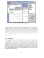
5.2 FLaNEL . . . . . . . . . . . . . . . .
5.2.1 Overview . . . . . . . . . . .
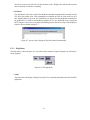
5.2.2 Main Window . . . . . . . . .
5.2.3 Sidebar . . . . . . . . . . . .
5.2.4 Internal “TAL File” windows .
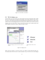
5.2.5 File Handling . . . . . . . . .
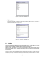
5.2.6 TAL views . . . . . . . . . .
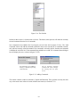
5.2.7 Graphical Map view . . . . .
5.2.8 Class Diagram . . . . . . . .
.
.
.
.
.
.
.
.
.
.
.
.
.
.
.
.
.
.
.
.
.
.
.
.
.
.
.
.
.
.
.
.
.
.
.
.
.
.
.
.
.
.
.
.
.
.
.
.
.
.
.
.
.
.
.
.
.
.
.
.
.
.
.
.
.
.
.
.
.
.
.
.
.
.
.
.
.
.
.
.
.
.
.
.
.
.
.
.
.
.
.
.
.
.
.
.
.
.
.
.
.
.
.
.
.
.
.
.
.
.
.
.
.
.
.
.
.
.
.
.
.
.
.
.
.
.
.
.
.
.
.
.
.
.
.
.
.
.
.
.
.
.
.
.
.
.
.
.
.
.
.
.
.
.
.
.
.
.
.
.
.
.
.
.
.
.
.
.
.
.
.
.
.
.
.
.
.
.
.
.
.
.
.
.
.
.
.
.
.
.
.
.
.
.
.
.
.
.
.
.
.
.
.
.
.
.
.
.
.
.
.
.
.
.
.
.
.
.
.
.
.
.
.
.
.
.
.
.
.
.
.
.
.
.
.
.
.
.
.
.
.
.
.
.
.
.
.
.
.
.
.
.
.
.
.
.
.
.
.
.
.
.
.
.
.
.
.
.
.
.
.
.
.
.
.
.
.
.
.
.
.
.
.
.
.
.
.
.
.
.
.
.
.
.
.
.
.
.
.
.
.
.
.
.
.
.
.
.
.
.
.
.
.
.
.
.
.
.
.
.
.
.
.
.
56
56
56
57
58
58
59
60
60
60
62
62
63
Problems & Solutions
6.1 Mechanical . . . . . . . . . . . . . . . . . . . .
6.1.1 The Walker Structural Problem . . . . . .
6.2 Electronic . . . . . . . . . . . . . . . . . . . . .
6.2.1 The Accelerating Motors Problem . . . .
6.2.2 The Battery Problem . . . . . . . . . . .
6.3 Organisation . . . . . . . . . . . . . . . . . . . .
6.4 External Factors . . . . . . . . . . . . . . . . . .
6.4.1 Project Bench . . . . . . . . . . . . . . .
6.4.2 Lab Access . . . . . . . . . . . . . . . .
6.4.3 Balance Chip Supply . . . . . . . . . . .
6.4.4 Circuit Design and Production Assistance
6.4.5 Motor Shortage . . . . . . . . . . . . . .
6.4.6 Rotation Sensor Shortage . . . . . . . . .
.
.
.
.
.
.
.
.
.
.
.
.
.
.
.
.
.
.
.
.
.
.
.
.
.
.
.
.
.
.
.
.
.
.
.
.
.
.
.
.
.
.
.
.
.
.
.
.
.
.
.
.
.
.
.
.
.
.
.
.
.
.
.
.
.
.
.
.
.
.
.
.
.
.
.
.
.
.
.
.
.
.
.
.
.
.
.
.
.
.
.
.
.
.
.
.
.
.
.
.
.
.
.
.
.
.
.
.
.
.
.
.
.
.
.
.
.
.
.
.
.
.
.
.
.
.
.
.
.
.
.
.
.
.
.
.
.
.
.
.
.
.
.
.
.
.
.
.
.
.
.
.
.
.
.
.
.
.
.
.
.
.
.
.
.
.
.
.
.
.
.
.
.
.
.
.
.
.
.
.
.
.
.
.
.
.
.
.
.
.
.
.
.
.
.
.
.
.
.
.
.
.
.
.
.
.
.
.
.
.
.
.
.
.
.
.
.
.
.
.
.
.
.
.
.
.
.
.
.
.
.
.
.
.
.
.
.
.
.
.
.
.
.
.
.
.
.
.
.
.
.
.
.
.
.
.
.
.
.
.
.
.
.
.
.
.
.
.
.
.
.
.
.
65
65
65
65
65
66
66
67
67
67
68
68
68
68
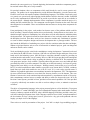
Conclusion
7.1 Aim . . . . . . . . . . . . . . .
7.2 Evaluation . . . . . . . . . . . .
7.3 Current Status . . . . . . . . . .
7.3.1 Complete Components .
7.3.2 Incomplete Components
7.4 Future Work . . . . . . . . . . .
7.4.1 Grabber . . . . . . . . .
7.4.2 PoWDER . . . . . . . .
7.4.3 TALComm . . . . . . .
7.5 TAL / TALC . . . . . . . . . . .
7.5.1 FLaNEL . . . . . . . .
7.5.2 Walker Chassis . . . . .
7.5.3 Balance System . . . . .
7.5.4 Course . . . . . . . . .
7.6 Summary of Achievements . . .
.
.
.
.
.
.
.
.
.
.
.
.
.
.
.
.
.
.
.
.
.
.
.
.
.
.
.
.
.
.
.
.
.
.
.
.
.
.
.
.
.
.
.
.
.
.
.
.
.
.
.
.
.
.
.
.
.
.
.
.
.
.
.
.
.
.
.
.
.
.
.
.
.
.
.
.
.
.
.
.
.
.
.
.
.
.
.
.
.
.
.
.
.
.
.
.
.
.
.
.
.
.
.
.
.
.
.
.
.
.
.
.
.
.
.
.
.
.
.
.
.
.
.
.
.
.
.
.
.
.
.
.
.
.
.
.
.
.
.
.
.
.
.
.
.
.
.
.
.
.
.
.
.
.
.
.
.
.
.
.
.
.
.
.
.
.
.
.
.
.
.
.
.
.
.
.
.
.
.
.
.
.
.
.
.
.
.
.
.
.
.
.
.
.
.
.
.
.
.
.
.
.
.
.
.
.
.
.
.
.
.
.
.
.
.
.
.
.
.
.
.
.
.
.
.
.
.
.
.
.
.
.
.
.
.
.
.
.
.
.
.
.
.
.
.
.
.
.
.
.
.
.
.
.
.
.
.
.
.
.
.
.
.
.
.
.
.
.
.
.
.
.
.
.
.
.
.
.
.
.
.
.
.
.
.
.
.
.
.
.
.
.
.
.
.
.
.
.
.
.
.
.
.
.
.
.
.
.
.
.
.
.
.
.
.
69
69
69
71
71
72
72
72
73
73
73
73
73
73
74
74
.
.
.
.
.
.
.
.
.
.
.
.
.
.
.
.
.
.
.
.
.
.
.
.
.
.
.
.
.
.
.
.
.
.
.
.
.
.
.
.
.
.
.
.
.
.
.
.
.
.
.
.
.
.
.
.
.
.
.
.
.
.
.
.
.
.
.
.
.
.
.
.
.
.
.
2
.
.
.
.
.
.
.
.
.
.
.
.
.
.
.
.
.
.
.
.
.
.
.
.
.
.
.
.
.
.
.
.
.
.
.
.
.
.
.
.
.
.
.
.
.
.
.
.
.
.
.
.
.
.
.
.
.
.
.
.
Bibliography
75
A Summary Project Log
A.1 Alexnewton Alexander
A.2 Emma McGahon . . .
A.3 Ross McIlroy . . . . .
A.4 Chris Margach . . . . .
A.5 Robert Moir . . . . . .
.
.
.
.
.
.
.
.
.
.
.
.
.
.
.
.
.
.
.
.
.
.
.
.
.
.
.
.
.
.
.
.
.
.
.
.
.
.
.
.
.
.
.
.
.
.
.
.
.
.
.
.
.
.
.
.
.
.
.
.
.
.
.
.
.
.
.
.
.
.
.
.
.
.
.
.
.
.
.
.
.
.
.
.
.
.
.
.
.
.
.
.
.
.
.
.
.
.
.
.
.
.
.
.
.
.
.
.
.
.
.
.
.
.
.
.
.
.
.
.
.
.
.
.
.
.
.
.
.
.
.
.
.
.
.
.
.
.
.
.
.
.
.
.
.
.
.
.
.
.
.
.
.
.
.
.
.
.
.
.
.
.
.
.
.
.
.
.
.
.
.
.
.
.
.
76
76
77
78
79
80
B Contributions Summary
B.1 Alexnewton Alexander
B.2 Emma McGahon . . .
B.3 Ross McIlroy . . . . .
B.4 Chris Margach . . . . .
B.5 Robert Moir . . . . . .
.
.
.
.
.
.
.
.
.
.
.
.
.
.
.
.
.
.
.
.
.
.
.
.
.
.
.
.
.
.
.
.
.
.
.
.
.
.
.
.
.
.
.
.
.
.
.
.
.
.
.
.
.
.
.
.
.
.
.
.
.
.
.
.
.
.
.
.
.
.
.
.
.
.
.
.
.
.
.
.
.
.
.
.
.
.
.
.
.
.
.
.
.
.
.
.
.
.
.
.
.
.
.
.
.
.
.
.
.
.
.
.
.
.
.
.
.
.
.
.
.
.
.
.
.
.
.
.
.
.
.
.
.
.
.
.
.
.
.
.
.
.
.
.
.
.
.
.
.
.
.
.
.
.
.
.
.
.
.
.
.
.
.
.
.
.
.
.
.
.
.
.
.
.
.
81
81
81
82
83
83
C Team A Language (TAL) Reference Manual
84
D Team A Language Compiler (TALC) User Manual
87
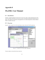
E FLaNEL User Manual
E.1 Introduction . . . . .
E.2 Overview . . . . . .
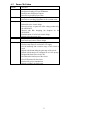
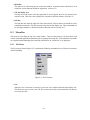
E.3 Menu Bar . . . . . .
E.3.1 File Menu . .
E.3.2 Tools Menu .
E.3.3 Help Menu .
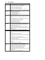
E.4 TAL file display area
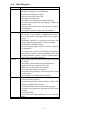
E.5 Side Bar . . . . . . .
88
88
88
89
89
91
92
93
95
.
.
.
.
.
.
.
.
.
.
.
.
.
.
.
.
.
.
.
.
.
.
.
.
.
.
.
.
.
.
.
.
.
.
.
.
.
.
.
.
.
.
.
.
.
.
.
.
.
.
.
.
.
.
.
.
.
.
.
.
.
.
.
.
.
.
.
.
.
.
.
.
.
.
.
.
.
.
.
.
.
.
.
.
.
.
.
.
.
.
.
.
.
.
.
.
.
.
.
.
.
.
.
.
.
.
.
.
.
.
.
.
.
.
.
.
.
.
.
.
.
.
.
.
.
.
.
.
.
.
.
.
.
.
.
.
.
.
.
.
.
.
.
.
.
.
.
.
.
.
.
.
.
.
.
.
.
.
.
.
.
.
.
.
.
.
.
.
.
.
.
.
.
.
.
.
.
.
.
.
.
.
.
.
.
.
.
.
.
.
.
.
.
.
.
.
.
.
.
.
.
.
.
.
.
.
.
.
.
.
.
.
.
.
.
.
.
.
.
.
.
.
.
.
.
.
.
.
.
.
.
.
.
.
.
.
.
.
.
.
.
.
.
.
.
.
.
.
.
.
.
.
.
.
.
.
.
.
.
.
.
.
.
.
.
.
.
.
.
.
.
.
.
.
.
.
.
.
.
.
.
.
.
.
.
.
.
.
F Powder Reference Manual
97
F.1 Using PoWDER . . . . . . . . . . . . . . . . . . . . . . . . . . . . . . . . . . . . . . . 97
G Team A Language for Communications (TALComm) Reference Manual
98
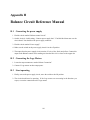
H Balance Circuit Reference Manual
101
H.1 Connecting the power supply . . . . . . . . . . . . . . . . . . . . . . . . . . . . . . . . 101
H.2 Connecting the Lego Motors . . . . . . . . . . . . . . . . . . . . . . . . . . . . . . . . 101
H.3 Start operating . . . . . . . . . . . . . . . . . . . . . . . . . . . . . . . . . . . . . . . . 101
I
Overall User Manual
I.1 Introduction . . . .
I.2 Equipment . . . . .
I.3 Course Layout . . .
I.4 Procedure . . . . .
I.4.1 Step One .
I.4.2 Step Two .
I.4.3 Step Three
I.4.4 Step Four .
I.4.5 Step Five .
I.4.6 Step Six . .
.
.
.
.
.
.
.
.
.
.
.
.
.
.
.
.
.
.
.
.
.
.
.
.
.
.
.
.
.
.
.
.
.
.
.
.
.
.
.
.
.
.
.
.
.
.
.
.
.
.
.
.
.
.
.
.
.
.
.
.
.
.
.
.
.
.
.
.
.
.
.
.
.
.
.
.
.
.
.
.
.
.
.
.
.
.
.
.
.
.
.
.
.
.
.
.
.
.
.
.
.
.
.
.
.
.
.
.
.
.
.
.
.
.
.
.
.
.
.
.
3
.
.
.
.
.
.
.
.
.
.
.
.
.
.
.
.
.
.
.
.
.
.
.
.
.
.
.
.
.
.
.
.
.
.
.
.
.
.
.
.
.
.
.
.
.
.
.
.
.
.
.
.
.
.
.
.
.
.
.
.
.
.
.
.
.
.
.
.
.
.
.
.
.
.
.
.
.
.
.
.
.
.
.
.
.
.
.
.
.
.
.
.
.
.
.
.
.
.
.
.
.
.
.
.
.
.
.
.
.
.
.
.
.
.
.
.
.
.
.
.
.
.
.
.
.
.
.
.
.
.
.
.
.
.
.
.
.
.
.
.
.
.
.
.
.
.
.
.
.
.
.
.
.
.
.
.
.
.
.
.
.
.
.
.
.
.
.
.
.
.
.
.
.
.
.
.
.
.
.
.
.
.
.
.
.
.
.
.
.
.
.
.
.
.
.
.
.
.
.
.
.
.
.
.
.
.
.
.
.
.
.
.
.
.
.
.
.
.
.
.
.
.
.
.
.
.
.
.
.
.
.
.
.
.
.
.
.
.
.
.
.
.
.
.
.
.
.
.
.
.
102
102
102
103
103
103
103
103
103
103
103
I.4.7
I.4.8
I.4.9
J
Step Seven . . . . . . . . . . . . . . . . . . . . . . . . . . . . . . . . . . . . . 104
Step Eight . . . . . . . . . . . . . . . . . . . . . . . . . . . . . . . . . . . . . . 104
Step Nine . . . . . . . . . . . . . . . . . . . . . . . . . . . . . . . . . . . . . . 104
Code Listings
J.1 Robots NQC Code . . . . .
J.2 PoWDER / TALComm Code
J.3 TALC Code . . . . . . . . .
J.4 FLaNEL Code . . . . . . . .
.
.
.
.
.
.
.
.
.
.
.
.
.
.
.
.
.
.
.
.
.
.
.
.
.
.
.
.
.
.
.
.
.
.
.
.
.
.
.
.
.
.
.
.
.
.
.
.
.
.
.
.
.
.
.
.
.
.
.
.
.
.
.
.
.
.
.
.
.
.
.
.
.
.
.
.
.
.
.
.
.
.
.
.
.
.
.
.
.
.
.
.
.
.
.
.
.
.
.
.
.
.
.
.
.
.
.
.
.
.
.
.
.
.
.
.
.
.
.
.
.
.
.
.
.
.
.
.
105
106
107
108
109
K Data Sheets
110
L OrCAD Footprint Tutorial
111
4
Chapter 1
Introduction
With the emergence of wireless networking technologies, one of the most important considerations in
the design of modern electronic systems is their ability to communicate with each other, and in so doing,
perform a task which neither could achieve alone. With this in mind, we decided to produce a team of
robots which could work together to complete an obstacle course.
Our Project Brief involved the creation of two robots, with differing abilities, which could work as a team
to solve a problem that neither could solve alone. The creation of these robots would test our knowledge
of both electronic hardware design, software creation and the interfacing of these two components, thus
allowing us to demonstrate the full breadth of knowledge we have gained while studying a joint degree
in Electronic and Software Engineering.
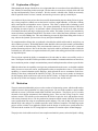
1.1 Preliminaries
We modeled the assault course and the two robots using the “Lego Mindstorms Robotic Invention System”. The flexibility of Lego, and wide range of parts available, allow a large number of mechanical
systems to be created without the need for specialized manufacturing of custom components. Central
to the Lego Mindstorms kit is a micro-controller, contained within an RCX brick. This controller can
accept inputs from a variety of sensors, and can also control the speed and direction of up to three motors
by way of a number of output ports. An Infrared Port is also built into the RCX Brick, which allows for
communication between different RCX’s. The RCX micro-controller can also be reprogrammed using
an IR tower connected to a host.
These various abilities have allowed a wide range of projects to be implemented using the Mindstorms
Invention Kit, and have created a sizeable following of enthusiasts around the world. The simplistic
programming language provided by Lego to control the RCX has prompted many individuals to develop
alternative languages which are capable of controling the RCX. One of the most notable of these is a
language created by Dave Baum called Not-Quite-C (NQC). This language is syntactically very similar
to regular C, allowing many of the features you would expect, such as loops, if-statments, and even
multi-threaded Tasks. Unlike many other languages created for the RCX, NQC does not replace the
RCX firmware provided by Lego, but instead, compiles down to the same bytecode used in Lego’s own
control language. While this reduces a number of complications when programming the RCX brick, it
does impose a number of fundimental limitations on the power of NQC, for example, a program has an
absolute limit of 32 global and 8 local variables. There is also no support for pointers or structures in
NQC. The RCX has a limited amount of RAM, and so there is only a small amount of memory available
for any programs that are used to control the RCX.
5
1.2 Explanation of Project
When planning the design of both robots, it was important that we created two robots with differing abilities, which were interesting in their own right. The first robot we created was a biped, which can walk
up steps and dynamically correct its balance. We also created a wheeled robot, which can accurately
track its position relative to where it started, and search a given area to pick up a small object.
As a number of the previous projects have been used for demonstration purposes during University opendays, where prospective students can see the kind of work they might undertake, we felt that a walking
robot would provide an immediate source of interest. This robot is equiped with a balancing system
which prevents loss of stability in two ways. The system dynamically corrects the balance of the robot
by adjusting its centre of gravity. An electronic control circuit measures any tilt in the robot, and tries
to counteract that tilt by moving a weight on top of the walker. The balance system is also controlled by
means of software programmed into the RCX. Just before a foot is lifted, the centre of balance is moved,
so that it is over the standing foot. This static balancing prevents the biped from falling when it takes a
step, whereas the dynamic system corrects for any unexpected instabilities.
To complement this walking robot, we produced a wheeled robot which could search for, and pick up, an
object within a given area. We decided that this robot should be able to navigate around a predetermined
course by means of dead reckoning. This necessitated the creation of a very accurate drive system and
position measuring software. Due to the fact that a lego brick could be positioned anywhere within the
searchable area, the software was required to find its way back to the starting position of the search from
an unspecified point.
The two robots required the ability to communicate with each other in order to successfully work as a
team. The IR ports on the RCX blocks provided us with a method of communication between the robots,
but we needed to produce a simple communications protocol and implement the software to provide this.
While the robots have the capability to navigate one predetermined assault course, we decided to add the
ability for users to create new courses, and program the robots to complete these courses. To provide this
capability, we created a domain specific language, which allowed the user to concentrate on the functionality of the robots, rather than the intricacies of NQC. The next stage was to produce an interpreter
for this language which could create code used by the RCX bricks. A simple Java application was then
layered on top of this new language to further ease the creation of new assault courses.
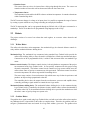
1.3 Motivation
The main motivation behind this project was the creation of an interesting system, which would teach us
valuable lessons in the organisation of a major group project. We were keen to produce a project which
reflected our course’s joint slant towards both electronics and software. This project gave us a sizable
electronic circuit design component in the balancing circuit. There was also a large scope for varied
software creation. The software used to control the RCX brick is quite low level, and interfaces closely
with various electronic devices. We also produced an interpreter which created valid NQC from assault
course specification files using our own domain specific language. The code for this was higher in level
than the NQC code, and gave us valuable experience in the creation of compilers. The final stage in the
project was the creation of an application which eased the design of assault course specification files.
This involved the creation of a GUI using high level constructs in a modern object oriented language.
The project also involved the creation of some complex mechanical systems, such as the biped’s walking
6
system and the grabber’s accurate drive system. As well as providing us with the opportunity to gain experience in a field usually outwith that of our course, we also obtained valuable practice in the interface
between a mechanical system and electronic and software control systems.
A large number of the previous projects involved studying the use of Lego Mindstorm kits for educational purposes, particularly aimed at schools. We felt that the physical designs of the walker and
grabber robots were interesting and unusual enough to capture the attention of school children, either in
an educational setting, or for demonstration purposes.
1.4 Document Outline
The remainder of this report provides detailed descriptions of the design of all of the major hardware and
software components. The reasoning behind major decisions in the design of the system are analysed
and described. The final section of the report details the lessons which were learned during the project,
and its value as a learning experience. The main sections are described below:
• Biped Walker Design
Describes the mechanical design of the biped walker and the process by which a believable walking motion is created through the use of joints, based on animals’ legs.
• Electronic Balance Circuit
Descibes the design of the electronic balance control system, and how this was integrated onto the
biped, by way of a mechanical weight shifting system.
• Biped Software Design
Describes the main sections in the software used to control the movement and static balance of
the biped robot.
• Wheeled Grabber Design
Describes the design of an accurate drive system using lego, a brick sensing system and an efficient
grabber, using the minimum number of motors possible.
• Grabber Software Design
Describes the software used to control the grabber robot. This software measures the precise
distance and direction from a point, so that it can return to that point at any time. The code also
implements a searching algorithm to find a brick within a certain area.
• Communication System
Describes the process by which the various robots communicate with each other.
• Design of Assault Course Specification Language
Describes the creation of an interpreter for our Domain Specific Language, and the process by
which it creates valid bytecode for the RCX micro-controller.
• Design of Assault Course Creation Program
Describes the creation of the software which can be used to graphically produce Assault Course
Specification files.
7
• Problems Overcome
Discusses the major problems that were confronted during the course of the project, and describes
how we overcame these.
8
Chapter 2
Descriptive Overview
2.1 Background
Our project team consisted of five students, Alexnewton Alexander, Chris Margach, Emma McGahon,
Robert Moir and Ross McIlroy. Our supervisor was Dr Dickman who is based in Glasgow University’s Computer Science department. We had weekly meetings with Dr Dickman where we were able
to discuss our progress and plan the week ahead. If we experienced any difficulties over the duration of
the project we were able to seek advice from Dr. Dickman and the Electronic and software engineering(ESE) course director, Dr. MacAuley.
We had the responsibility for organising our team, deciding on a project plan and enforcing any deadlines
for deliverable documents. We had approximately fifteen weeks to complete our project, demonstrate
our final product, submit a project dissertation and provide a short presentation on our project experience.
2.2 Lego Mindstorms
The project involved the creation of various robots using Lego Mindstorms Kits. These kits contained
standard Lego Technic pieces such as cogs, axles and supporting blocks. The kit also contained a number of motors which can be used to turn axles and cogs, giving a dynamic system able to perform a
number of functions.
Unique in the Mindstorms kit is the ability to program these motors using a specially created microcontroller called an RCX. This RCX can accept inputs from various sensor inputs, which gives the designer
the ability to control the Lego motors using external stimuli. Lego provides a number of sensors which
can be interfaced directly onto the RCX, some of which are described below:
• Touch Sensor
This is the most simple sensor created by Lego for the Mindstorms kit. It consists of a small block,
containing a push switch. The RCX can be setup to give a value of ’1’ to a touched switch and ’0’
to a non pressed switch.
• Light Sensor
This sensor is contained within a standard sized lego brick. It contains a small LED and a light
sensor at one end. This light sensor can be used to detect the amount of light, from the LED,
which is reflected by objects, and so can be used to differentiate between light and dark objects.
The range possible range on the RCX is between ’0’ and ’100’.
9
• Rotation Sensor
This sensor allows an axle to be inserted into a hole going through the sensor. The sensor can
count the number of times this axle has been turned since the last sensor clear.
• Temperature Sensor
The temperature sensor enables the RCX to detect variations in temprature. It contains a thermistor
within a standard lego brick.
The RCX measures changes in voltage at its inputs, thus it is possible to augment the range of sensors
by creating a system which can vary voltage according to some physical medium.
The RCX microcontroller can be reprogramed through an IR link with a USB tower connected to a
standard pc. The RCX can therefore be programmed using languages such as NQC.
2.3 Robots
The project consists of a team of two robots that work together, to overcome various obstacles and
challenges.
2.3.1 Walker Robot
The walker robot has three main components: the mechanical legs, the electronic balance control circuitry and the mechanical balance shifting device.
Mechanical Legs The mechanical legs constructed using standard Lego Technic bricks provide the
walker robot with the ability to move forward in a straight line, ascend steps and descend slopes.
Connected to an RCX programmable brick, it achieves this movement from one standard Lego
motor.
Balance control circuitry The balance control circuitry is the only hardware component of the project
not constructed using Lego Technic bricks. It was specially constructed for this project using
electronic components. The balance control circuit controls two Lego motors which move the
walker robots centre of gravity to counteract any tilt experienced. The balance control circuit has
two main components: the sensor stage and the controlling device.
The sensor stage consists of an accelerometer chip which senses any tilt that it experiences and
produces an output voltage proportional to that tilt.
The controlling device takes the outputs from the accelerometer, processes and amplifies them,
eventually producing a signal suitable to control the two Lego motors.
Mechanical balance shifting device The mechanical balance shifting device is also constructed using
Lego Technic bricks. Controlled by the balance circuitry and the walker software downloaded to
the walker robot’s RCX, the mechanical balance shifting device provides the mechanism to shift
the robot’s centre of gravity along two separate axis.
2.3.2 Grabber Robot
The grabber robot, again created using Lego Technic bricks was built to assist the walker robot complete
any challenges that it is impossible for the walker to complete alone. Therefore, the grabber robot can
navigate a predetermined course and search for a Lego brick within a given area. The grabber robot
10
robot has three main components that provide this functionality: the drive system, the grabber system
and the sensor system.
Drive System The drive system allows the grabber robot to move forward and turn in one direction with
excellent precision.
Grabber system The grabber system allows the the grabber robot to pick up and place down an object
in front of it.
Sensor System The sensor system lets the grabber robot detect any object placed in front of it.
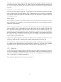
2.4 Communications
Each RCX block is equiped with a half-duplex Infra-Red tranceiver. This allows the RCX to communicate via IR with other RCXs, a PC or any other IR device which uses the same IR protocol. Communication in the project, between the tasks running on the robots and those on the course elements, is carried
out via this tranceiver using a higher level protocol. This protocol, PoWDER, was created by the team
to provide a simple method of delivering instructions between all robots. PoWDER enables all robots to
send and receive commands to and from each other in a language called TALComm, also created by the
team. TALComm contains comon commands which the robots will require each other to execute.
To program the robots themselves, a low level IR link is used between the PC and RCX to upload
programs. This facility is implemented by the project’s front-end, FLaNEL, in order to send course
deatils to the robots. The robots will then proceed along the course, using PoWDER and TALComm
whenever they require to communicate instructions.
2.5 Course
The obstacle course consists of two Lego gates controlled by a third RCX programmable brick. One
motor is required to open each gate. The first gate is opened when a touch sensor is depressed. The
second gate is opened when the controlling RCX receives the correct message. Both gates remain open
once they have been triggered. The obstacle course must be set up according to a set of rules described
in Appendix I.
11
Chapter 3
Robotic Design
Two robots cross the “assault” course by working together as a team. Walker the biped can only move
in a straight line, so must be aided by the wheeled robot, Grabber, which can search flat areas for objects
and follow programmed routes. Grabber, on the other hand, relies on Walker to move to places Grabber
is unable to move to, such as up steps and down slops.
3.1 Walker
The walker robot is bipedal, it can walk in a straight line, climb stairs, and descend slopes. It keeps its
balance by using the balance circuit described in Section 3.1.2. This circuit controls servo motors which
move the robot’s centre of gravity to counteract any forces conspiring to unbalance the walker whilst it
is moving.
The walker robot has four main components. These are:• The mechanical legs
• The electronic balance control circuitry
• The mechanical balance shifting device
• The RCX command code
These components of the robot are discussed in detail in the following sections.
3.1.1 Leg Mechanics
Basic Design
The main principle behind the walker legs design was to translate a mechanical turning motion, provided
by the electric Lego motors, into a simple walking motion, where a leg is lifted up and forwards, then
pushed down and back. This walking motion is essentially linear.
The same rotational drive is applied to both legs from one motor. By connecting the legs such that one
leg’s rotation is 180◦ out of phase with the other’s. This means that one leg will be bearing the robot’s
weight, and propelling it forwards, while the other leg is free to lift up and move into position for the
next step.
12
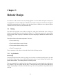
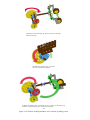
Chicken Prototype
The first prototype developed was based on a “chicken walker” design. Each leg comprised of two struts
in line, with a fixed ankle and foot, and a reversed knee joint (Figure /reffig:chicken1). The rear strut
was attached to a free swinging hip joint, and the forward strut attached to a cam rotating around the
hip. It was decided that the hip joint should be a simple hinge, as this made the drive system easier to
connect to the two legs. Additionally, Lego ball + socket joints were not large enough nor strong enough
to bear the weight of an RCX.
This simplistic design provided a vague walking motion, but was unable to stand unaided. It did demonstrate that the cam would provide the right kind of motion however.
Chicken Prototype II
The walking motion was simplified by reducing the leg to a single strut with a reversed knee and fixed
ankle and foot, and fixing the cam shaft some distance below the knee (Figure 3.2).
By gearing down the rotational drive from the motor to two identical cogs in line, and fixing the cam
to the outer rims of both of these cogs, the cam was provided with more power at the cost of speed.
More importantly, this made the ’cam’ move rotationally, whilst the knee joints made each leg move in
the diagonal, linear motion required. This improvement did not increase the viability of the prototype,
which was still unable to stand without support, but it was logged for use in the final design.
For the sake of continuity, the rotating strut which transfers drive to the legs from the motor will be
referred to as the cam for the course of this document.
Chicken Prototype III
The third design kept the new cam arrangement, but replaced the fixed ankle and foot with a heel joint
halfway down the leg from the knee, and a fixed toe (Figure 3.3. The new toe comprised of a large Lego
wheel laid flat. This gave the robot much better balance.
A shock absorber was attached across the heel joint. Unfortunately, the shocks were not able to support
the weight of the RCX.
Attempts to lower the walker’s centre of gravity by hanging the chassis below the knees proved unworkable, as the balance system employed in the design requires free movement on the horizontal plane. The
high knees obstructed this movement.
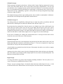
Dog Prototype
It is always advisable to copy nature when designing something mechanical. The knee joints were reversed. The legs now resembled the back legs of a dog.
The new ’zig-zag’ leg design (Figure 3.4) made the robot much more stable along the Y-axis, i.e. it did
not fall forward or back. When the heels were fixed in place, the robot could now stand unaided.
13
(a) (Arrows indicate moving parts)
(b)
(c)
Figure 3.1: The Chicken Prototype Mk. 1
14
(a)
(b)
(c)
Figure 3.2: The Chicken Prototype Mk. 2
15
(a)
(b)
(c)
Figure 3.3: The Chicken Prototype Mk. 3
16
The main problem was now to provide a drive system that stopped the legs collapsing, yet still allowed
them to move when required. An attempt was made to replace the cam drive arrangement with a system
of string tendons strung down the front and back of the robot skeleton. Pulling the string one way would
tighten the string in front of the thigh, straightening the knee, and also the string on the back of the calf,
straightening the heel. This would provide the ’down and back’ motion. Pulling the string the other way
would tighten the back of the thigh and front shin, bending the knee and heel, providing the ’up and
forward’ motion.
This design proved problematic, the main difficulty being the tightening of the string only bending one
joint at a time, rather than both together. It came to the attention of the designer that a horse’s back
leg cannot bend the knee without bending the ankle as well. This gave rise to the idea that a system of
cogs running down the length of the calf would restrict the legs’ movement, as a horse’s back legs are
restricted.
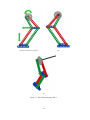
Horse Prototype
When the extra cogs were added to the legs (Figure 3.5), it became apparent that the cam arrangement
from the second prototype would easily drive the legs. The tendon drive system was abandoned. The
new legs had two 40 - tooth cogs at each end of the middle leg section, connected together by three 24
- tooth cogs down the middle of the struts. The large cogs each have a pin (a short cross axle piece)
through them, which fixes their movement to the thigh and foot struts respectively.
The feet were modified by replacing the back strut with string and looping elastic bands, under tension,
around the front of the foot and the base of the shin. This pulled the string taut so it acted like an achilles
tendon. This enabled the ankle to bend forward and spring back to the horizontal, allowing the robot to
walk down slopes without leaning forwards.
It was found that one motor provided insufficient power to drive the legs. It is easy to connect additional
motors to the same drive shaft, however. These motors can be connected to the same source in parallel,
which doubles the available torque at the expense of battery lifespan.
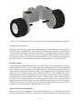
Final Design
The entire robot chassis had to be strengthened to take the combined weight of the RCX and balancing
device along with their batteries. Many of the leg components were doubled up to increase the available
support. The main load bearing plastic cross axles were replaced with steel bolts and threaded rods.
Polystyrene cement was used to fuse together some of the bricks in the chassis, making it more rigid.
Three motors were geared down and connected to the main drive shaft, on the underside of the chassis,
surrounded by a support framework of Lego bricks fused together with polystyrene cement. Finally, a
Lego rotation sensor was attached to the rear of the chassis, and meshed to the right side rear 40 tooth
cog via another 40 tooth cog. This sensor is used by the walker’s RCX to determine the position of the
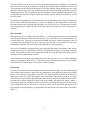
legs in motion for control purposes. A photograph of the final design of the walker robot is provided at
figure 3.6.
17
(a)
(b)
(c)
Figure 3.4: The Dog Prototype
18
(a)
(b)
(c)
Figure 3.5: The Horse Prototype
19
(a)
(b)
(c)
Figure 3.6: The final walker robot legs, with slider unit attached.
20
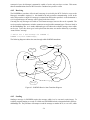
3.1.2 Balance Circuitry
The balance control circuit is an essential addition to our project, it is this combined with the slider
mechanism (chapter 3.1.3) that work together to dynamically balance the walker robot.
Design Description
The first step in the design process of the balance system consisted of establishing the system’s goals.
In our case we had a situation where the goal was to control the tilt angle of the walker robot.
The second step was to identify the variables to control, in our case we only wanted to control the tilt
angle of the walker robot. In order to do this, we required a device that could measure the tilt angle of an
object. After some research we found that it’s possible to sense the tilt-angle of an object electronically,
using an accelerometer device.
Not only did we have to sense the tilt angle of the robot, we also required a device that could adjust the
tilt angle of the robot. The slider mechanism combined with a pair of Lego motors allowed us to perform
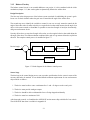
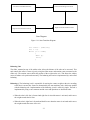
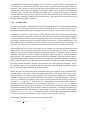
this task. The complete control process is modelled in figure 3.7.
Desired Angle +
Circuit
−
Motors
ControllingDevice Actuator
Slider
Mechanism
Output
Plant
Accelerometer
Sensor
Figure 3.7: Block diagram for the balance control process
Sensor Stage
The third step in the control design process was to produce specifications for the sensor in terms of the
accuracy that had to be attained. It was decided that the minimum requirements for our accelerometer
chip would be as follows...
1. The device must be able to sense a minimum tilt of + and - 45 degrees on the x and y-axis.
2. The device must provide analogue outputs.
3. The device should be able to withstand the force of being dropped accidentally.
4. The device must be a maximum of £20 .
After thorough research, we found that the ADXL202E accelerometer chip satisfied all of our criteria.
The ADXL2O2E data sheet is available in Appendix K.
21
On receipt of the ADXL202E chip we discovered that it had no input/output pins, but instead had metal
contacts flush with the chip itself. We decided to have it surface mounted onto a small printed circuit
board(PCB) to make it possible for us to create cheap practise circuits on socket board.
In order to surface mount a chip, a footprint for the chip must be developed. The footprint allows technicians to see where the chip should be placed, where to place any connection holes and what size the
holes and copper tracks should be on a PCB. We created a footprint for the ADXL202E chip using a
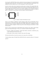
computer aided design tool - OrCAD. The result of surface mounting the chip was the device shown in
figure 3.8. The tutorial we used to help us create the footprint is located in Appendix L.
ST
T2
COM
Yout
1
2
3
4
8
7
6
5
Vdd
Xfilt
Yfilt
Xout
Figure 3.8: Surface mounted ADXL202E pin Layout
There are two methods of obtaining the required analogue outputs from the ADXL202E. The first
method involves reconstructing the duty-cycled outputs(digital outputs) found at Xout and Yout. This
method requires the use of passive components such as resistors and capacitors, in hindsight this method
appears to be simpler to implement. If there is any time for work on this project in the future we would
test this method.
Instead, we chose to implement the second method that takes advantage of the analogue outputs already
present at the Xfilt and Yfilt outputs. There are two constraints associated with these outputs:
• Each has a 32kohm output impedance. Which means that they cannot drive a load directly, they
require buffering before they become useful.
• Each produce an offset voltage of around 2.5Volts with a 5Volts supply.
We had to take both of these factors into account at a later stage of the circuit design.
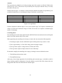
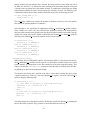
Using the analogue outputs, Xfilt and Yfilt the ADXL202E must be connected as shown in 3.9 for normal
operation:
22
Figure 3.9: Circuit diagram of the sensor stage.
Circuit Explanation
Parts of the balance control circuit require a supply voltage of 12V whereas the ADXL202E can only
handle a maximum input voltage of 5V. The 5V1 zener diode(D1), the 47uF capacitor(C1) and the 1.5k
resistor(R1) ensure that the voltage to the ADXL202E chip never exceeds 5V. The 100ohm resistor(R2)
and 0.1nF capacitor(C2) provide power supply decoupling to the chip. The remaining 2.2nF capacitors,
C3 and C4 filter the Xfilt and Yfilt outputs at pins 7 and 6 respectively. The 1Mega ohm resistor R3 is
required as per the data sheet (Appendix K).
Process Stage
The fourth step of the control design process involves the design and implementation of the controlling
device, the actuators and the plant stages of the control process. As shown in figure 3.7, the controlling device in our system is the remaining circuitry, the Lego motors are the actuators and the Slider
mechanism is the plant. See chapter 3.1.3 for a description of the slider mechanism.
23
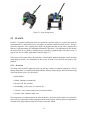
Actuators
The Lego motors we decided to use in the processing stage of the system were Electric-Technic minimotors 9v(Lego 71427). These motors were provided as part of our project materials so they were easily
accessible at no extra cost.
The data shown in figure 3.10, which we extracted from the technical description of Lego Motors[1] was
essential information that we used during the design of the balance control circuit.
Input Voltage(Volts)
4.5
7
9
12
Input Current(Amps)
0.12
0.12
0.12
0.12
Electrical Power(Watts)
0.54
0.85
1.1
1.5
Figure 3.10: Lego Motors
From the information collated in figure 3.10 we can see that the Lego 71427 requires a minimum input
voltage of 4.5Volts and a maximum voltage of 12Volts. We can also see it requires a minimum supply
current of 120mAmps.
Controlling Device
The controlling device takes input signals from the ADXL202E and converts them into the useful signals
that are used in the actuator stage of our system.
When approaching the controlling device design, we had to take into account the following details:
• The analogue outputs from the ADXL202E require buffering before they can drive a load.
• There is approximately a 2.5Volt offset voltage from the analogue outputs.
• The Lego motors require a voltage between 4.5Volts and 12Volts.
• The Lego motors require an input current of at least 120mAmps.
We decided to simplify the controlling device stage by dividing it into two individual sections
1. The Buffering and correction section.
2. The amplification stage.
After trying various design approaches for the buffering and correction stage, we decided to tackle it
using a summing amplifier configuration. Using this method we get rid of the offset voltage at the summing junction and at the same time buffer the resultant signal.
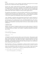
24
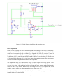
Figure 3.11: Circuit Diagram of buffering and correction stage
Circuit Explanation
Initially a TLO71 op-amp was used for the buffering and correction stage of the circuit. Unfortunately,
the output signal from this op-amp was extremely noisy, instead of designing around this problem we
decided to use a low-noise op-amp the NE24655 (see Appendix K). The 0.1uF capacitors C7 and C8
provide power supply decoupling for the op-amp. The remaining capacitor C10 reduces the noise present
on the output of the op-amp. Resistors R11, R12 and R13 allow us to get rid of the 2.5V offset present
on Xfilt and Yfilt by allowing a -2.5v signal to be input to the summing junction. The potentiometer
allows us to account for any drift the ADXL202E chip experiences.
The Amplification stage was a little easier to design, it is just a simple non-inverting op-amp. After
testing the op-amps available in the University we found that they did not produce adequate current to
drive the Lego motors. After additional research we found that power op-amps produce high enough
currents to run the Lego motors. We decided to use Analog Devices L165 (see Appendix K), which
produces a current greater than 120mAmps and produces voltages up to 12V.
On receipt the L165 power op-amps we found that they had an unusual shape, so again we created a new
footprint for the L165 using OrCAD.
25
One difficulty that arose in the amplification stage was deciding on a reasonable gain. The table shown
in figure 3.12 shows the tilt angle experienced by the walker robot, the voltage output from the buffering
and correction stage of the circuit and the output voltage we estimated was required for the Lego Motors.
Tilt Angle
(degrees)
-45
-30
-15
0
15
30
45
Accelerometer
Output
-0.265
-0.188
-0.097
0
0.097
0.188
0.265
Required
voltage(Volts)
12
9
5
0
5
9
12
Gain
45.28
47.87
51.55
0
51.55
47.87
45.28
Figure 3.12:
Average Gain =
45.28 + 47.87 + 51.55
= 48.23
3.00
W e can approximate this to a gain of 50
This is equivalent to the non-inverting op-amp configuration shown in figure 3.13.
Input
+
Output
−
R1
R2
Figure 3.13: Non-Inverting Amplifier
Where resistors R1 and R2 are calculated using the equation:
R1 + R2
(3.1)
R2
One possible resistor combination we tried, that satisfied the above equation is R1 = 500k, R2 = 10k.
Gain =
26
We decided to make it possible to alter the Gain since our calculations were formed using estimates. We
inserted sockets in place of R1 and R2, allowing us to easily change R1 and R2, thus changing the gain.
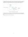
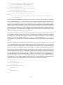
In order for the L165 to operate in the above context we had to set it up as shown in figure 3.14.
Figure 3.14: Circuit diagram of gain stage
The only design decision we had to make at this stage of the circuit was the value of resistors R16 and
R17 that allow us to set the gain of the circuit. The rest of this stage was setup as shown in the data sheet
K.
The complete and final circuit design is shown in 3.15.
27
Figure 3.15: Complete circuit diagram
3.1.3 Slider
Controlled by the balance circuitry and the Walker code, the slider mechanism moves a counterweight
around the top of the robot. The counterweight consists of several heavy items: the slider’s own motors;
the RCX and it’s battery pack; and the balance circuit with it’s battery pack.
The slider is required to action movements of the counterweight, dictated by the balance sensors. A
voltage is generated by the balance circuitry as the walker tilts, this is applied to the motors, which will
in turn move either axis of the slider. The slider is also controlled statically by the walker software when
each step is taken. Before a step is taken, the centre of gravity of the robot must be placed above the
trailing foot. This movement is steady and predictable and so is coded into the main task of the walker’s
software.
Separate X and Y axes are considered in the movement of the slider. Two motors are used in the system,
one for each axis, which allow the counterweight to be moved to any point within a regular rectangular
area on top of the walker. More movement is afforded across the walkers shoulders than from its front to
its back. This is because more tilt appears across the shoulders due to the nature of the walkers stepping
motion.
The first slider design was produced and built early in the project. It was demonstrated on top of an
early walker design to show the concept of it’s operation. However, this first design was too heavy and
slightly unrobust which meant it had to be redesigned. The biggest concern was that, with all the equipment required to be placed on top of the walker, each component would have to be reduced in size and
weight. With this in mind the slider mechanism underwent a total redesign.
28
Redesigning
The slider was designed again from scratch with the emphasis on small size. A smaller size means more
movement along an axis, due to the device taking up less distance on the rack. More importantly, a
smaller design will also weigh less. The only restriction on the area of the slider’s base is the size of the
two motors required to drive each axis. So to start with, the motors were placed side by side by side, as
compactly as possible. Due to the discrete spacing involved in Lego technic and the sizing of the cogs,
the motors had to be oriented in different directions, allowing gears to be more easily connected to the
front of the motors.
The first design transmitted movement down a vertical shaft to a set of cogs underneath the slider floor.
In this way, most of the gearing for that axis was separated from the rest of the entire mechanism. However, the gearing required to use a shaft not only took up a larger than required amount of space, but
was unstable. When the mechanism jammed or was placed under heavy load, some of the cogs on the
vertical shaft could be forced out of position along the shaft. Whenever this happened, the motor would
spin freely and no motion would be transmitted. If this were to happen, the the walker would be unable
to correct its balance on that axis and so almost certainly fall over. A large lagging effect also resulted
from the many small cogs required under the floor.
Several cogs had to be used to enable the mechanism to drive itself from either end. The whole mechanism sits on top of that axis, which means that driving from only one side, but in two directions, can
make the mechanism raise up off the track. It will raise on the non-driving side when accelerating as a
motorcycle does. If the slider were moving upwards with the non-driving side first, then without suitable
fixtures it would fall off the robot.
The second design used a belt-drive by the way of a Lego rubber loop or band. There was a significant reduction in the area required above the floor, as no gears were needed to translate the motion.
However, the belt had insufficient grip to operate under a heavy load, which unfortunately included the
load required for normal operation. When grip was achieved, the lagging effect was compounded by the
elasticity of the band stretching it before gripping.
The second axis, which moves the RCX over the slider, was never able to be constructed compactly. The
reason being that the gearing has to be worked around and over the two motors. This was the reason for
placing the first axis’ gearing under the floor. The first design used a feed straight off the second motor
to drive one side of the rack. However, transmitting movement over the top of the slider with this design
was not possible in a robust way. Fixing the axis on both sides was too problematic, given the space
constraints. Also, driving on only one side reduced the amount of power on the axis significantly.
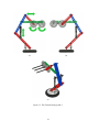
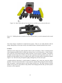
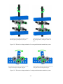
Current Design
The current design uses a similar idea to the band for the shoulder axis, but instead of a band a large cog
is used to drive two thin blade cogs (Figure 3.16). These blade cogs drive the gearing directly. Fewer
small cogs are now used under the floor which results in slightly less lag. However the main gain is that
more load can be taken as there is no axle for the blade cogs to slip along upwards and zero elasticity.
The second walking direction axis was not radically different to the original attempt. The current design
uses one main axle to equally drive the rack. Only one gear is used to translate the motion from the
driving motor, which then passes it to the axle. This methods requires two “walls” on either side on the
mechanism to hold the gearing in place. To stop the track from tilting, unconnected cogs were placed at
the ends of the walls. These hold it in position while moving two or from one of its extents while tilted.
29
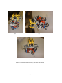
Figure 3.16: Row of gears driven from the motor by two blade gears to move the first axis
Figure 3.17: Walking-direction (second) axis driven on both sides by one axle connected to the second
motor.
The current design is functional as required for the project. There are two main problems with the
design, although they will not pose a major risk within the limits of normal operation on the course.
Problems
Within the current design, the greatest problem is that of a lack of robustness. This is a constant problem
when designing mechanical devices which must tolerate forces in several directions. A lack of robustness on the axis of movement along the walkers direction of travel can pose a problem. The build of
the slider means that large forces on the cogs will cause separation of the Lego bricks on the walls. To
partially solve the problem, braces were placed on the sides of the slider walls to help hold it together
(Figure 3.18). The bricks may still separate slightly, although they will not come apart.
A smaller problem is that there is a small amount of mechanical “lag” on the axis across the walkers
shoulders. This arises from the number of cogs required to transmit motion along the slider internally.
Each cog requires a small movement to come in contact with the next. This delay increases with the
number of cogs, however, the problem is only noticed when changing direction and, given the speed of
the motors, can be neglected.
30
Figure 3.18: Braces must be put in place to hold the walls together
3.1.4 Walker Code
This section will discuss the overall software design approach used to code the walker robot. The software design for this project turned out to be a somewhat formidable task. As with most projects, there
are usually many unexpected challenges. The biggest challenges came from working with the walker
robot. After analysing the robot, an initial program design could be planned. The one major restriction
to consider was the size of the program. The size of the program turned out to be most critical because
of the memory limits of the RCX (approximately 32k). The program had to be large enough to complete
the task, but small enough to download (and run correctly) to the RCX. We carefully created parallel
tasks and global variables to satisfy the above problem.
The walker robot software was divided into three major sections representing walking motion, balancingunit and communication with other robot. The walking motion section coordinates the movement of the
robot based on a rotational sensor and the drive motors. The balancing process controls the centre of
gravity of the walker robot, so the robot able to walk without falling over. The communication process
deals with the communication between this walker robot and the grabber robot or the gate keeper RCX.
These sections combined into a framework that coordinates the operation of the robot. During development each section was developed in isolation, tested to ensure that it worked correctly, then incorporated
into the main program.
The walker robot is powered by three motors, all of which are connected in parallel to a single output
of the RCX. This gives the walker the necessary power to walk, without using more RCX outputs than
necessary.
The walking motion and the balance unit tasks are run concurrently in this system. This gives the Walker
the ability to balance and walk at the same time. The design of both of these tasks is described below.
Walking motion
One of the primary tasks of the walker robot is to walk over a certain distance. The walking motion
task provides the means for moving the walker robot while other operations are occurring. The walking
motion task contains a set of functions which directly drive the motors controlling the robotic legs. This
task also checks the cam position of the walker robot by way of a rotation sensor connected to the walker
31
drive axle.
The walking motion task provides interface between the leg motors and the rest of the code that drives
the robot, allowing low level functions such as start turning legs and emergency stop.
State-machine
The state-machine task is used to check the state of the robot. Since the walker robot can only walk in
a straight line, we decided to have four states. The states describe the position of the walker legs. We
used the following states:
• Both feet down left foot forward.
• Right foot raised left foot forward.
• Left foot raised right foot forward.
• Both feet down right foot forward.
The rotation sensor mounted on the walker robot, is used to check the cam position of the robot. States
are determined by the rotation sensor values. In this, task the rotation sensor values are represented by a
variable called rot drive. The following code checks the robot’s state:
if ( (rot_drive < 6) && (rot_drive >= 0) )
state = LF_FWD_RF_UP;
else if ( (rot_drive >= 15) && (rot_drive <= 18) )
state = LF_FWD_BOTH_DN;
else if ( (rot_drive >= 6) && (rot_drive <= 10) )
state = RF_FWD_BOTH_DN;
else if ( (rot_drive > 10) && (rot_drive < 15) )
state = RF_FWD_LF_UP;
The State Transition diagram in figure 3.19 shows the possible transitions between these states.
Walking
The walking task is one of the major operations of the walker robot. This task allows the robot to move
from one position to another. The walking() task uses some the following functions to accomplish it
task:
Walk () The walk subroutine is used to move the walker forward by two steps. When this subroutine is
called, the motors are activated until the rotation sensor mounted on the robot value becomes eight.
We assumed that the robots initial state is left foot forward and both feet down, so after the above
procedure the robots state will be right foot forward and both feet down. After a small period, the
motors are activated again until the rotation sensor value becomes 16. After this procedure the
robots state will become the initial state.
Move() The move function is used to move the walker robot forward by the distance specified by the
variable “cent”. The move function calls the walk subroutine the number of times necessary to
move the walker forward by the specified amount. The following code explains the move function:
32
Left foot forward Both feet down
Left foot forward right foot raised
Right foot forward both feet down
Right foot forward left foot raised
State Diagram
Figure 3.19: State Transition Diagram.
int count = (cent/10);
int i = 0;
while (i <= count)
{
walk ();
i=i+1;
}
Balancing Unit
The slider, mounted on top of the walker robot, allows the balance of the robot to be corrected. This
task control sthe walker’s centre of gravity using the slider motors and rotation sensor connected to the
slider axle. The rotation sensor checks the position of the weight on the axis. This allows the walkers
centre of balance to be positioned accurately. The balancing unit section is implemented by a task called
balancing.
Balancing () The balancing() task is responsible for moving the counter weight on the axis according
to the robot’s current state. States are determined by the state-machine() task, which runs parallel
with the balancing task. Implementation of the balancing () task is relatively simple. The task is
implemented by using a case statement and the cases and operations are described below.
• When the robot’s left foot is forward and right foot is raised the motor is activated, and it moves
the weight towards the left foot.
• When the robot’s right foot is forward and both feet are down the motor is activated and it moves
the weight towards the centre of the axis.
33
• When the robot’s right foot is forward and left foot is down the motor is activated and it moves
the weight towards the right foot.
• When the robot’s left foot is forward and both feet are down the motor is activated and it moves
the weight towards the centre of the axis.
34
3.2 Grabber
The second robot which we designed for the project is a wheeled grabber robot. This robot is intended
to assisted the walking robot in a number of ways. The robot can be programmed to perform a number
of tasks using a language we developed called TAL (see Section 4.1). The grabber robot can then
transmit some of these messages to the walker using TALComm (see Section 4.3), allowing the grabber
to control the walker’s movement. This wheeled robot also has the ability to search for, and pick up an
object. There were a number of systems which had to be designed and built to allow the grabber robot
to perform these functions. The final grabber design is shown below (figure 3.20).
(a) Side view of Grabber
(b) Turning the vertical shaft
clockwise moves the worm
gear down, turning the bottom
two gears.
Figure 3.20: The final grabber design.
3.2.1 Drive System
The grabber bot was designed from the start to be an autonomous machine, which could move around
a predefined assault course without human intervention. The Robot must therefore have the ability to
follow a predetermined route, either being hard coded into the robot, or through external markers such
as lines.
A line-follower would be relatively simple to implement in a robot, using light sensors to follow a blackpainted line. When there is an increase in light intensity, it can be assumed that the robot has driven off
the line. The robot would then stop and turn, until the light sensor detects the dark line and would then
continue to follow it.
While this would satisfy the route following requirement, there are a number of problems associated
with it. First, this line-following system would only allow for a static, predetermined path to be followed with no branching. While this would have been adequate for finding a way around the course,
it would not allow for a flexible searching algorithm. Since we intended using a light sensor to detect
objects in front of the robot, there would also have been difficulty in distinguishing between an object to
35
Figure 3.21: Each wheel is powered by a separate motor and so can move independently of the other.
be picked up, and the dark line.
We therefore chose to design a robot which could independently evaluate the distance from its start-point
without reference to external markers. This would allow the grabber bot to find its way around the course
by measurement of the distance travelled in each direction. The robot would also be able to search a
large area for an object, using a light sensor. One of the problems with this system is the requirement
for a very accurate drive, as any slight error would accumulate over time, and prevent measurement of
the grabber’s position. The following three designs were prototyped before a decision was made.
Two Motor Design
The first design was a traditional system where each wheel was powered by a separate motor, as demonstrated in figure 3.21. This was a very simple lego system to design and build. It allowed forward and
reverse motion, as well as the ability to turn in both directions. The main problem with this drive was
that it required two outputs from the RCX to operate. This would leave only one output for use with the
grabber arm, and so limit the potential options available for its design. Another complication with this
design was that both motors were required to turn at the same rate when a certain voltage was applied.
Very often the two motors had differences in friction or efficiency and so turned at different speeds.
The problem was exaccerbated by the fact that electric motors are designed to be more efficient when
turning in one direction, than the other. Since the usual design for this system uses two motors turing in
different directions to move the robot forward, the motors turn at different speeds, giving a slight curve
to the robot’s forward motion, thus sending the grabber bot off course.
Worm Gear Directional Transmission
The most effective way of stopping the wheels turning at different rates is to connect them with a common drive to a single motor. If this was carried out in a conventional manner, the robot would only be
36
able to go forwards and backwards, which is inadequate for effective searching. To resolve this it is
possible to create a directional transmission system, which turns a separate drive, depending upon the
direction of the motor. This will allow the robot to move forwards, and turn in one direction, using
only one motor. There is also a substantial increase in the precision of measured direction and distance,
because it is impossible for the wheels to turn at different rates, as they are physically connected to the
same motor.
One way of producing a directional transmission system is to use a worm gear which can turn two separate sets of gears, as shown in figure 3.22. The worm gear is free to move up and down the axle it is
attached to, and in fact, it is easier for the worm gear to slide like this, than it is to turn the cogs. When
the motor turns anticlockwise, the worm gear moves up the gears until it hits the brick at the top. Now
the worm gear cannot move up any further, and so is forced to turn the top two gears as shown in figure 3.22(a). When the motor turns clockwise, the worm gear moves back down the axle (figure 3.22(b))
until it hits the bottom brick, and turns the lower set of gears.
This system did allow for accurate forward and turning measurement and only used one motor. The
problem with this design became apparent when the robot changed from moving forwards to turning, or
vice versa. To allow the worm gear to move up the axle, the two sets of gears had to be aligned correctly,
which meant that one set often had to turn, moving the wheels in the process. As this realignment was
almost always random, there was no way of correcting this. Also, the worm would occasionally stick
between the two sets of gears, and jam the grabber’s motion entirely.
A further problem with this design was the lack of torque which could be transfered by the worm
gear. When the rest of the robot was added, it became too heavy to be powered by one motor at any
reasonable speed. When more motors were added in parallel, the worm gears started to slip, and so
prevented reliable movement.
Swing Arm Directional Transmission
It is also possible to design a directional transmission system, which relies upon a swinging arm to drive
two separate drives (figure 3.23). This design relies on friction to swing the arm in the right direction.
In an ideal, frictionless world, this design would never work. This design was based upon a brief discription given in the O’Reilly Unofficial Lego Mindstorms book [2].
When the motor is turned clockwise, it swings the arm to the right, as shown in figure 3.23(a). This
allows the top gear to mesh with the right-most gear, and turn this drive. When the motor is turned
anticlockwise (figure 3.23(b)), the arm swings to the left, allowing the top gear to turn the left-most gear.
This design has all the advantages of the worm gear system, such as relying on only one motor, and
increasing the precision of forward, and rotational motion. It also prevented the loss of accuracy when
the robot changed from moving forwards, to turning, since the gears meshed easily without a substantial
realignment.
Since this system used standard cogs, rather than a worm gear, the torque from the motor was more
efficiently transfered to the wheels. There was also less likelihood of the gears slipping when placed
under a heavy load.
37
(a) Turning the vertical shaft anticlockwise moves
the worm gear up, turning the top two gears.
(b) Turning the vertical shaft clockwise moves
the worm gear down, turning the bottom two
gears.
Figure 3.22: The basic working mechanics of a worm gear directional transmission system.
(a) Turning the bottom gear clockwise moves the
swing arm to the right, turning the right gears.
(b) Turning the bottom gear anticlockwise moves the
swing arm to the left, turning the left gears.
Figure 3.23: The basic working mechanics of a swing arm directional transmission system.
38
Final Drive Design
For the final design of the grabber bot’s drive system we decided on the above swing arm directional
transmission. This gave the benefit of only requiring one motor and also greatly increased the accuracy
of the grabber’s movement. Although the wheels cannot turn at different rates with this system, the
wheels can slip, or be offset by uneven ground, which can send the grabber bot off course. To reduce the
possibility of slippage, we used large rubbery wheels. We also designed the grabber arm in such a way
that it could pick up an object in front of either wheel, so preventing the robot being sent off course by
driving over an uneven object.
To measure the distance travelled by the robot, a rotation sensor was connected to the drive axle. This
gave a large increase in accuracy over simply measuring the amount of time a motor is running, because
it does not rely on the motor’s speed. Since the speed of a motor can change dramatically with battery
votage, a timed measurement becomes increasingly inaccurate, while the rotation sensor system remains
correct.
3.2.2 Grabber System
One of the main requirements for the Grabber Robot is its ability to search for, and pick up an object.
To do this the robot needs both a grabbing mechanism and a sensor with which it can identify objects to
be picked up.
Due to the grabber robot being an independent robot working within a team, it was preferable that it
used only one RCX brick. This limited us to a maximum of three independent motors, one of which
was already being used to control the robot’s motion. There was also a limit of three sensor ports, with
one again taken up by a rotation sensor measuring the distance travelled by the robot. These constraints
restricted the grabbing system to a maximum of two motors, with two sensor ports available to detect
the object and, if necessary, measure the position of the grabbing mechanism.
As with the Drive system, we researched and prototyped a number of different designs before a final
decision was taken.
Crane Design
The first design we investigated was a traditional crane design. This system uses a number of joints to
move a claw into a position over the object, then uses this claw to pick up the object. Due to the jointed
system, this design has very good mobility, and can pick up objects from a large area.
The main problem with this design, when used on the grabber bot, is the large number of motors it
requires. For an effective crane, each joint should be independently driven. Since the claw also needs
its own motor, the constraint that only two motors can be used means that the crane could only have
one independent joint, which would severely limit the one main advantage of this design, its increased
mobility.
Another disadvantage is that the robot would need to know where the claw is positioned, to be able to
move it correctly when picking up an object. To do so accurately, a number of sensors would have to be
used, thus taking up valuable sensor ports, which could have been used for other functions.
39
Lifter Design
The Lifter System has a scoop mounted on a vertically moving slider, so that it can be raised or lowered.
This system is much like that employed by fork lift trucks. This system can be implemented quite easily,
with only one motor required. There is also no need for any sensors to measure the position of the scoop.
While this is a reasonably simple design to produce, there are a number of difficulties which hinder its
use. Firstly, it is very difficult to scoop up an object from the ground, especially a round object which
just tends to roll away from the scoop. The object can also fall off of the scoop when the robot turns.
There is also a problem when releasing the object as it cannot be placed with great accuracy.
Cam and Cog Lifting System
This design is quite a complex system which allows a grabbing claw to be opened and closed, as well
as being raised and lowered, all from one motor. When the motor is turned in one direction, the arm is
first lowered to the ground. The grabbing claw then starts to close, until it has fully grabbed the object
to be picked up. The arm then rises to lift the object off of the ground. When the motor is turned in
the opposite direction the arm is lowered, the claw then opens, releasing the object, and the arm rises up
again.
The system relies on cams to move the arm upwards when the claw is open, and on one cog riding up
another locked cog to move the arm up when the claw is closed. An overview of the mechanism is
shown in figure 3.24(a) with the direction of drive shown, using arrows, when the claw is closing.
When the grabbing claw is open the cams are used to move the arm up or down as shown in figure 3.24(b). When the grabbing claw is closed, either on an object, or on itself, the cams are moving
downwards and so cannot lift the arm. Instead we take advantage of the fact that the top cog (red in
figure 3.24(c)) becomes locked when the claw is closed. If the motor keeps turning then this locked cog
is forced to ride up the turning yellow cog, in turn lifting the arm.
This design is a very efficient use of one motor, and also has no need for sensors to measure the position
of the arm. It is also reliable, and will always pick up and replace objects from the same spot in front
of the robot. There are some problems with this system. There is not a great deal of motion possible
in the arm, as the cams can only move the arm by a finite amount. This means that the whole grabbing
assembly must be lower to the ground and objects cannot be lifted very high above the ground. The
motor is also put under a large amount of strain when the arm is being moved up by the cog. This means
that the motor has to be geared down, which in turn slows the grabbing motion.
Final Design
For the final design it was decided that we should use the Cam and Cog Lifting System. We modified
this design to have a larger grabbing area, so that an object could be lifted from any point in front of the
robot. This was done by changing the vertical grabbing motion into a horizontal sweep and grab motion.
As the claw is closed, any objects on the outskirts of the grabbing range are swept into the centre, then
picked up. We also added a touch sensor, which is activated when the arm has been raised to the fully
upward position. This allows the motion of the grabbing mechanism to be controlled by simply running
the motor in one direction, until the touch sensor is pressed to grab an object, then running the motor in
the opposite direction to release the object, again stopping when the touch sensor is pressed.
40
(a) The motor drives the large cog, which in turn lowers the cams,
and closes the claw.
(b) When the grabbing claw is open the
cams move the arm up and down.
(c) When the grabbing claw is closed the red cog is locked. As the Yellow cog
continues to turn the whole arm is forced to move upwards.
41
Figure 3.24: The basic working mechanics of a Cam and Cog lifting system.
3.2.3 Sensor System
We decided, early on in the project, to use a light sensor to detect objects in front of the grabber, and
initially this sensor was placed on the grabbing arm, facing down towards the ground. If the robot is
travelling on a light coloured surface, then dark objects could be detected by a change in the light sensor’s output.
The problem this system has is that it can only detect objects in a very small area, and this robot needs to
detect objects anywhere along its width. Our initial solution to this problem was to use an array of these
downward facing light sensors. With the reduced number of sensor ports available on an RCX brick,
this would have required some form of electronic multiplexing, and while possible, we felt this was not
an effective solution.
We decided to use a light gate system, where a beam of light is aimed horizontally into a light sensor,
from one side of the robot to the other. If an object moves into this area, it breaks the beam, which can
be detected by the light sensor. This system allows the gate to detect an object in front of any part of it.
This light gate system presented a new problem. To allow objects to be detected before they reached the
grabbing mechanism, the light source and light sensor had to be placed on arms which extended beyond
the reach of the grabbing claw. When an object is released by the grabber, the robot has to move away
from it, without disurbing the newly placed object. Due to the directional drive system, the robot can
only move forward or turn in an anticlockwise direction but cannot reverse, meaning the only way to
avoid the object is to turn, then move. When the sensor arms were added they swept the object away as
the robot turned. The arms could not simply be raised as they would then not be able to detect the object
initially. To solve this problem we added a mechanism which could raise and lower the arm on the right
side. This enabled the robot to have the arm down when searching, but then raise the arm when turning
to prevent objects just placed on the ground from being swept away.
3.2.4 Searching Algorithm
A number of searching algorithms exist, many of which are specific to a particular environment. The
searching algorithm we chose for our first prototype was very simple: Search a small circular area, then
move to another space and search a small circular area again - keep on searching until it finds an object.
If it could not find any objects in the user specified area it would come back to the stating point.
When we tried to implement this algorithm, we built a roaming robot with a light sensor in front of
it, another light sensor facing downwards and a grabber arm that connected with a touch sensor. The
grabber arm of the robot could grab and drop small objects.
Initially, the robot spun for 360 degrees and scanned for an object. The scanning was done by the light
sensor on the front of the robot. If an object was found, the robot moved towards the object and stopped
in front of it by using a downward facing light sensor. If an object was not found then the robot moved
to another area and started searching again. The circular areas were randomly selected by the robot, so,
unfortunately, it sometimes searched in an already searched area.
We were not successful on this approach because it was very difficult to backtrack the robot’s path to the
initial position. In addition, it could not perform a search an area which contained an obstacle. Due to
these limitations we simplified the searching algorithm to the current design, which looks for objects in
a linear manner by traveling up and down strips of the area to be searched. The Grabber used the sensor
system previously described to detect an object in front of it.
42
A major difficulty with the robot is getting it to move or turn by a precise amount. A timing approach
was tried where a motor was started, the task went to sleep for a specified time, and then the motor was
turned off. This worked to a point, but it had major positioning inaccuracies, arising when the robot’s
weight shifted, or the surface area changed, or the batteries drained. These inaccuracies would become
worse over time, as the robot was incapable of detecting errors. To improve the accuracy of the robot
we used connected a rotation sensor to the drive system. We could then measure the distance traveled
by measuring the number of rotations of the rotation sensor. This technique was also used to measure
the angle which the grabber is turning by.
3.2.5 Grabber Code
Once the basic mechanics of the grabber robot had been designed and built, we could start programming
the robot’s RCX with code to control its movement and grabbing motion. This then allowed us to implement the searching and distance measurement features used for the control of the robot as a whole.
We decided to structure this code so that the various functions of the robot, such as grab or turn, could
easily be called upon, as functions or subroutine calls. This meant that the main task within the grabber
code would basically consist of an initial setup phase, then a list of calls which could easily be chopped
and changed, allowing the grabber to complete different assault courses. This structuring became even
more important when we decided that the robots could be reprogrammed using the TAL language (see
Section 4.1) as it allowed TAL commands to be implemented using only a few lines of NQC code.
When creating code in NQC there are two main ways of splitting code, functions and subroutines. Both
allow sections of code to be called from another section, as you would expect, but there are a number of
differences between NQC and normal programming languages such as C. Functions in NQC can accept
arguments, but cannot return values. Unlike most languages, functions in NQC are always expanded as
inline functions. This means that each call to function results in another copy of the function’s code being included in the program, which can lead to excessive code size. Unlike inline functions, subroutines
allow a single copy of code to be shared between several different callers. This makes subroutines much
more space efficient than inline functions, but subroutines have some significant restrictions. First of
all, subroutines cannot use any arguments. Also one subroutine cannot call another subroutine. There is
also a restriction of eight subroutines in any NQC program.
Initially the code was written so that tasks which didn’t require any arguments, such as grab and release,
used subroutines to save space. Tasks which required parameters, such as move which requires a distance and direction were written as inline functions, since the parameters could be passed as arguments.
Although this made the code readable and look like code written in a standard language, it turned out
to be a very inefficient use of memory space. The two tasks performed by the robot most often turned
out to be move() and turn(). Both of these were implemented using functions to allow distance or
direction to be passed as arguments, but this meant that each call to move() or turn() resulted in
another chunk of code taking up space in the RCX. The solution to this would be to write these functions
as subroutines instead, except, since subroutines cannot use arguments, we needed to find another way
to pass information to them. The solution we decided upon was to use global variables, which would be
set up before a move() or turn() command was made. Although this meant that these commands
were a two stage process, it resulted in a massive increase in memory space efficiency.
The following procedures were created to control the grabber bot:
• calibrate arm()
43
The calibrate arm function is used in the setup phase of the main task. When called, it moves the
grabber arm to the open upright position by turning on the grabber motor until the touch sensor is
activated by the rising arm.
• calibrate light()
The robot detects objects by noticing a drop in the light intensity sensed by the light sensor. To do
this, the robot needs to compare the current light intensity with a default ambient light intensity.
The calibrate light function samples the light intensity ten times at 100ms intervals then takes the
average of these readings and saves it as the ambient light intensity value. This function is called
in the setup phase of the main task. It is also called each time the searching algorithm changes
from searching an upward strip to a downward one (see searchBrick()). The ambient light
intensity value is reconfigured after each strip so that a bright light at one side of the search area
(such as sunlight) doesn’t prevent the sensor from functioning correctly.
• grab()
The grab subroutine, when called, runs the grabber motor forward. This lowers the arm, closes the
grabbing claws, then raises the arm again. The motor is stopped when the touch sensor is activated
by the rising arm. This was created as a subroutine so that it can be called multiple times, with
only one copy of the code.
• release()
The release subroutine is much like grab(), except it runs the motor in the opposite direction to
lower the arm, open the grabbing claws, then raise the arm.
• turn()
The turn subroutine turns the grabber, to the left, by the number of quarter turns specified in
the Quarters global variable. The subroutine multiplies the Quarters variable by the number of
rotations of the rotation sensor necessary to turn the robot by one quarter of a full turn. The
drive motor is then turned in reverse until the rotation sensor’s value is equal to this value. The
subroutine then updates the direction variable using the following code:
direction += Quarters;
direction %= 4;
The direction variable now contains a value between 0 and 3 which corresponds to the current
direction of the robot.
• moveFwd()
The moveFwd subroutine is used to move the grabber robot forward by the number of cm specified
in the CMdistance global variable. In much the same way as the turn subroutine, this subroutine
starts by finding the amount of rotations it should turn the motor for using the following code:
int Turn_Count = ((CMdistance / 10) * tenCM) +
((CMdistance % 10) * (tenCM / 10));
This code uses the tenCM constant, which stores the number of rotations necessary to move the
robot 10 cm forwards.
Since the robot uses the swing arm directional transmission system, there was another factor to
be taken into account by both the turn and moveFwd subroutines. If the robot was previously
44
turning, and has now been asked to move forward, the swing arm has to move from one side to
the other (See Section 3.2.1), which takes more rotations of the motor than when the swing arm
is already at the cog which moves the grabber forward. To combat this, a global flag was added
which indicated whether the robot’s last movement was forwards, or a turn. The following code
is then used to add to the necessary rotation count if the swing arm is in the wrong position:
if (has_moved_Fwd == 0)
Turn_Count += 6;
The Turn Count variable now contains the number of rotations necessary to move the grabber
forwards by the specified number of centimetres.
This subroutine is also responsible for updating the distance x and distance y global variables.
These variables are used to store the position of the grabber in relation to its initial position.
Since the robot can only turn by quarter turns, the direction global variable can be used to specify
whether the current movement is added or subtracted from distance x or distance y using the
following code (SENSOR 3 returns the rotation sensor’s current value):
if (direction == 0)
distance_y += SENSOR_3;
else if (direction == 1)
distance_x -= SENSOR_3;
else if (direction == 2)
distance_y -= SENSOR_3;
else if (direction == 3)
distance_x += SENSOR_3;
• moveToInitialPos()
When called, the moveToInitialPos function will return the grabber to the point where the distance x and distance y variables are both equal to zero. Since these variables can be reset, a point
can be “marked” by setting them to zero, then returned to at any time using this function. This
feature is used by the searchBrick() function to return the robot to a known point, after having picked up an object from an unknown location.
The function first corrects the x position of the robot. It does this by turning the robot so that
it points towards the x=0 line (eg. turn east if distance x is negative, turn west if direction x is
positive) using the following code:
if (distance_x > 0) {
/* turn west in relation to starting direction
Quarters = (5 - direction) % 4;
turn ();
} else {
/* turn east in relation to starting direction */
Quarters = (3 - direction) % 4;
turn ();
}
The function then moves the robot forward by the distance specified in distance x, returning the
robot to the initial x position. The y position is corrected in much the same way.
45
• searchBrick()
The searchBrick function allows the grabber robot to search a predetermined rectangular area for
a lego brick, or any other object which can be detected by it. The function searches a rectangle of
a given length and width in centimetres to the right, and forward from the grabber’s position.
The function searches the rectangle in a number of length-ways strips. It starts by moving forward
the distance given by the length variable, while trying to detect an object. Since this involves
preforming two tasks at the same time, we decided that we would use multiple threads. A separate
thread (or “task” in NQC) is created which moves the grabber forwards by the given length variable. When this task is complete it signals the main task using a global flag. The main task waits,
either for this flag to be set high, or for an object to be sensed in front of the robot. In either case the
fwd strip task is terminated, which stops the robot from moving forward. If an object is detected,
the distance measurement variables are updated to the current position, as fwd strip was stopped
before it could update them. The object is then picked up and the moveToInitialPos()
function is called to return the robot to the position at the start of the search. If the fwd strip task
was stopped because the end of a strip was reached, then the function moves the robot, so that it
is pointing down the next strip and continues searching until the grabber has searched the whole
width of the search area.
46
Chapter 4
Communications
Two of the major project tasks were enabling the robots to cooperate and making the course generic.
This was achieved by creating an IR communication protocol and also forcing the walker and the gate to
communicate as an addition to the course specification. It was decided that in order to make the course
more generic, the grabber would be able to receive instructions based on the course layout. Also that the
grabber would then pass relevant walking instructions to the walker unit. Finally a user-specified key
would be relayed via the walker to the second gate.
To achieve this functionality, several communication components were developed. Namely: a domain
specific language, TAL; a compiler for this, TALC; a protocol for communication between the grabber, walker and gates, PoWDER; and finally a java front-end for uploading instructions to the grabber,
FLANEL. Together, these components provide the communications necessary to run the course.
4.1 TAL
When we decided that the various robots should be re-programmable we had two main options. The
first would be to create a number of header files containing functions and subroutines which control the
robots. The user programming the robot could then include these header files in a NQC file, then call
these subroutines to command the robot to complete an assault course. The second option was to create a
simple programming language and compiler which would be specially created to control the robots. We
decided on the second of these options, to create our own language, for a number of reasons. Firsly, we
could create a language which would be specific to the programming of robots, so making the code more
understandable to the user. This approach also made it possible to optimise code (for example, using
global variables and functions, see Section 3.2.5) without increasing the complexity of the commands
needed to control the robots.
It was important that the language we created was as simple to understand as possible to let users, not
familiar with programming, use “Team A Language” (TAL) to control the robots. With this in mind,
we decided that statements should be as close as possible to the English language sentences used to
describe such a command. To enable the compiler (TALC) to differentiate between statements, the
end of statements are also indicated with a semicolon. This means that a TAL file consists of a list of
commands. For example, the following would be used to move 10 cm to the north, grab an object, then
release that object at the start point:
move north 10;
grab;
move south 10;
47
release;
For a description of the possible commands and the Bakus Naur Form of TAL see the TAL Reference
Manual (Appendix C).
Since this language will only be used to program the robots in order that they can complete an assault
course, such as the one we created, we felt that there was no need for control statements such as “if” or
“while” statements. These contol statements would have added a great deal of power to the language but
they are not necessary to control a robot through any of the assault courses we created, and would have
added to the complexity of what we wished to be a simple to understand language.
4.2 TALC
When we decided to create our own language we required a method of compiling this into byte-code
which could be understood by the RCX micro-controller. There were several ways in which this could
be acheived, some of which are listed below:
• Compile down to the standard byte-code used by the RCX micro-controller. The micro-controller
used in the RCX is based on the Hitachi H8/3292 and so the byte-code is available on the internet.
While it would be possible to compile to this byte-code, it would involve a huge amount of work
to create a compiler that produced code at this low level.
• Replace the standard firmware af the RCX with a Java virtual machine such as LEJOS. This would
allow Java class files to be installed and run on the RCX. It would then be possible to compile a
java class file based on a TAL file, which could then be downloaded to the robots and run. This
approach would involve substantially less work than compilation to byte-code, but would mean
that the Java virtual machine would take up much of the limited memory space available on the
RCX.
• Create an NQC file from the original TAL file. The NQC compiler can then be used to compile
this NQC file into byte-code for the RCX, and then download this code. This approach would
require less work on the part of the TAL compiler as the NQC compiler is utilized as part of this
compilation process.
We decided on the last of these options, to produce an NQC file from a TAL file, mainly because we had
already produced a NQC file which could control the Grabber robot, and so had a template from which
to work. This template contains a number of functions and subroutines which can be called to perform
the various functions of the robots (see section 3.2.5). This template was used to produce a header and
footer containing all of the code necessary to control the robot. Each TAL command is then implemented using a few lines of NQC, setting up global variables and calling the functions implemented in
the header and footer.
We split the compiler into three main sections: the parser which reads the TAL file and splits it into
statements, removing whitespace and comments as it does so; the command constructor which creates
a “Command” object, containing the TAL and NQC representation of the given a TAL statement; and
finally the main compiler which deals with the creation of the NQC file, and if instructed, the downloading of the file to the robot. It was split in this way to increase the modularisation of the code, but also to
enable the FLaNAL graphical application (see section 5.2) to use parts of TALC to perform functions,
such as creating a command from a single statement.
48
Parser
The Parser’s basic function is to remove whitespace and comments from the given TAL file, then split
the file into a list of statements from which a command list can be built.
The Parser class contains a method called TALCtoCommands. This method takes a TAL file and an
output stream as parameters and returns a CommandList. The CommandList returned will contain a list
of “Command” objects, created using the statements given in the TAL file (See the Command section
below). The output stream is used to display errors. Errors are directed to this output stream rather than
standard output so that FLaNEL can display error messages within a graphical text box.
This method uses a StreamTokenizer to extract the statements from the TAL file. This StreamTokenizer
is passed the TAL file and is then set up to separate tokens with a ’;’. This means that when nextToken()
is called the token will contain all characters between the current cursor position and the next semicolon,
i.e. the next TAL statement. The StreamTokenizer is then set up to ignore comments.
A new “Command” is created from each statement taken from the TAL file, using the constructor described below, and then added to the CommandList to be returned. If there is a syntax error in the statement being passed to the Command constructor then a NotValidCommandException will be thrown.
The parser catches this exception and prints an error message, taken from the exception, to the given
PrintStream. The command list is only returned if there are no errors, so that the compiler only creates
valid NQC files.
Command Creation
Within the TALC program a Command is an object used to store various parameters of a single TAL
command or statement. A Command will contain both the TAL and NQC representation of the function
it is expected to perform, for example a “move forward 10” command will contain the TAL representation as a string:
move forward 10;
as well as the NQC representation:
CMdistance = 10;
moveFwd();
A Command is created with a constructor which is passed a TAL statement. This statement is copied
into the TAL representation of the command, and is then used with the static method TALCtoNQC to
produce the NQC representation. This method, TALCtoNQC, is contained within another class called
CommandSet. Putting the stage which deals with the creation of NQC from TAL in a separate class
like this allows new commands to be added easily without making any changes to the Command class,
which is depended upon by many other classes.
When TALCtoNQC is called it uses a StringTokenizer to split the given TAL statement into separate
words, while removing any whitespace between these words. These tokens are passed as an array of
strings to the talcTokensToNqc method. This method uses an “if else” ladder to compare the first token
with that expected for a command, and tries to return the command represented by that word, e.g:
/* return the correct type of command */
if (talcTokens[0].equals ("move"))
return moveCommand (talcTokens);
49
else if (talcTokens[0].equals ("turn"))
return turnCommand (talcTokens);
else if (talcTokens[0].equals ("grab"))
return "grab();\n";
else if (talcTokens[0].equals ("release"))
return "release();\n";
else if (talcTokens[0].equals ("search"))
return searchCommand (talcTokens);
else
throw new NotValidCommandException(">> Unrecognized command: " +
talcTokens[0]);
As can be seen if the command is a simple one, such as “grab” or “release”, then the NQC representation
can be returned straight away. If the command is more complex, and requires other parameters, such
as the direction and distance in the move command, then another method is called to return the NQC.
If the first word in the TAL statement relates to none of these commands then a NotValidCommandException is thrown. This exception is passed a message which states that the syntax error was caused by
an unrecognized command, which can be displayed by the program handling the command creation, in
this case the parser. Other applications can handle the error in different ways, such as FLaNEL which
displays the message in a dialogue box (see section 5.2).
The methods which deal with the more complex commands are reasonably straight forward, using the
array of tokens to gain the parameters neccessary to create the NQC statement. In the move command,
for example, the TAL syntax states that move should be followed by the direction of travel, then the
distance, so the direction should be held in talcTokens[1] and the distance in talcTokens[2].
If any parameters are missing then a NotValidCommandException is thrown, with a message stating the
problem.
The only real difficulties encountered when creating the NQC from TAL statements were “move” and
“turn” commands which used an absolute compass direction (such as north, south, east or west). Turning
to an absolute direction requires that the current direction of the robot is known, so that the number of
quarters necessary to turn in that direction can be calculated. It would have been difficult to keep track of
the direction of the robot within the compiler as commands are not necessarily created in order (FLaNEL
can add commands to the centre of a CommandList, unlike the parser which goes through commands in
the order they appear in the TAL file). Instead we decided to take advantage of the fact that the grabber
robot already keeps track of its direction using a variable which contains a value corresponding to its
direction (0 for north, 1 for west etc.) as discussed in section 3.2.5. This direction variable could have
been used in an “if else” ladder, within the created NQC code, which would have selected the correct
number of quarters to turn depending on the current direction, for example to turn north:
if (direction == 0) {
Quarters = 0;
else if (direction == 1) {
Quarters = 3;
else if (direction == 2) {
Quarters = 2;
else {
Quarters = 1;
}
50
This code is not very efficient, and could take up a relatively large amount of memory if it had to be
used a number of times. Instead of this “if else” ladder, it was discovered that modulo 4 arithmetic could
be used. For example, the following line of code will evaluate the correct number of quarters needed to
turn north:
Quarters = (4 - direction) % 4;
Once the NQC representation is produced, it is passed back up to the Command constructor, which then
stores it, along with the TAL representation. These Command objects can be stored in a CommandList
object, then be used to either display the commands as a list of TAL statements, or compile the NQC file
one statement at a time.
Main Compiler
The Compiler class contains a static method compile, which takes the TAL file to be compiled, a boolean
specifying whether the commands are to be downloaded to the robot or not, and a PrintStream object to
which errors will be printed.
The file is first passed to the parser, to create a CommandList based on the file being compiled. If the
parse successfully creates a CommandList, with no syntax errors, then the compiler creates the NQC
file. A new file is created which has the same name as the TAL file, except is suffixed with “.nqc”. The
header NQC file, created from the grabber robot code template, is written to this new file. The compiler
then goes through the CommandList and writes the NQC corresponding to each command into the new
file. Finally, the footer is written to the end of the new file, creating a valid NQC file which can be
compiled and run on the grabber robot.
If the boolean argument “download” passed to the compiler is true, the compiler now starts a new external process, namely the NQC compiler, which compiles and downloads this new NQC file.
The Compiler class contains a main method which calls the compile method with the filename passed as
an argument, and the download boolean set depending upon whether the “-d” switch is used. Standard
output (System.out) is passed as the printstream, so that any errors are displayed on screen.
4.2.1 Conclusion
Overall, TALC has been created so that new commands can easily be added, by changing the CommandSet class and changing the header and footer files. The compiler could also be used to program robots,
other than the grabber, by using different headers and footers. For an explanation on how to actually use
TALC, see the TALC User Manual (Appendix D).
The overall class diagram for TALC can be seen in figure 4.1
51
Figure 4.1: The TALC Class Diagram
4.3 TALComm
4.3.1 Overview
TALComm, or Team A’s Language for Communication, is a set of commands which can be sent and
received between any two of the three robotic elements on the course. They are the Grabber, Walker,
and Gates. Included are enough instructions to remotely drive each of those elements. The communications required on the course are: to tell the walker when and how far to walk; to tell the walker
to relay data to the gate; and to tell the gate to open with the data from the grabber. These commands
are broken down into simpler TALComm commands then sent and received via PoWDER protocol calls.
When a command is received, it is the responsibility of the receiving robot to handle that command,
acknowledge it and act accordingly. E.g. two different robots would handle a move command differently due to their respective mechanics and programming. The available commands are listed in the
TALComm user Guide.
Also included in the command macros are static IDs for the individual robots. These allow them to
identify each other easily, without the need to implement any additional command types or handling.
52
The following diagram shows how tasks communicate with TALComm:
Figure 4.2: TALComm commands sent over PoWDER
4.3.2 Development
In order to support the communications which would take place on the course, a set of atomic commands were created. These commands exist only as a list of macros. These macros must be included at
compile time by each program which uses them. Each macro represents functionality which should be
implemented or handled by any robot on the course. Macros were chosen as they do not use any of the
variables in the RCXs limited memory. They can also be implemented easily and are stored in a single
file.
The commands also had to match those specified in TAL so that they could be produced in NQC from
TAL files. The sequence for compound commands also had to be set out in the same file as the macros.
This ensured that each device would act accordingly to each command and not fall out of sync.
4.3.3 Problems
The only problem faced in creating TAL, was the minor one of making sure that the macros could
not possibly interfere with the PoWDER macros. PoWDER was, however, created to minimise this
difficulty. Each TALComm macro will be different from the main control macros in PoWDER. However
the robot IDs are allowed to overlap if necessary.
4.4 PoWDER
In order to control the flow of data between the walker, grabber and gates, the PoWDER protocol was
designed and implemented. The Protocol of Walking Droid and Explorer Robots, is a simple flow control
protocol which enables instructions of TALComm to be sent between the robots. The main reason
for implementing PoWDER was to enable two robots to easily and reliably communicate with each
other via simple procedure calls. The two main procedures implemented by programs are POWDERrcv
and POWDERsndTALCOMM. A layer of communication is formed by POWDER on top of which the
programmer may only be interested in a single 8-bit message and a result integer (16-bit local variable).
4.4.1 Development
To develop the protocol the IR abilities of the RCX had to be understood. The RCX provides a Message()
function and a 16 byte transmit buffer. While the transmit buffer enables the RCX to send up to 16
53
consecutive bytes, the Message() command is capable of receive only one byte at a time. This means
that all communications between RCXs must be considered one packet at a time.
4.4.2 Receiving
The POWDERrcv procedure will wait until a message is received by the RCX. Exclusive access to the
Message() command is required, i.e. this should be the only procedure communicating via IR. At the
end of the procedure a single 8-bit message is returned into the location specified. As the destination is
a 16-bit signed integer, the message will be placed in the lower 8 bits.
Currently, the only messages receivable are TALComm messages, however this can be expanded. The
receive procedure implements a switch to enumerate several possible command types. These are listed in
the PowderBindings file. As it stands, additional types will reduce the available message values which
can be sent. To fix this, these types can be placed into the status area and be defined by a preceding
“status follows” message.
/* Waits for a new message via POWDER */
POWDER rcv(int& newMessage);
The following diagram outlines the states through which PoWDER transitions:
Deliver Message
(END)
Yes
START
Complete?
No
Update Status
No
New Message?
Yes
Yes
PoWDER?
Yes
Init?
Yes
No
No
Status?
TALComm?
No
No
(No)
Yes
Send Error
Init?
Yes
No
Status?
Yes
No
Other Type?
Figure 4.3: PoWDER Receive State-Transition Diagram
4.4.3 Sending
Sending a message via POWDER requires the message which is to be sent and a result integer. To
avoid the program hanging as a result of a failed send, POWDER includes a timeout defined in the PowderBindings file. The procedure will attempt to send the message to another RCX, or even a PC, which
54
must be running the POWDERrcv command. The returned status will be 1 for success and 0 for failure.
Currently, only one full sending procedure is implemented as this is all that is required for the project.
The procedure will send a TALComm message by identifying to the receiving device that a TALComm
message is about to be sent.
/* Sends a TALComm message via powder */
POWDER sndTALCOMM(int& result, int outMsg);
4.4.4 Error Handling
Both send and receive procedures use POWDER status messages to handle any problems. Mostly, the
status messages are used to detect and report if communication fall out of sync. There are no recovery
facilities in place to handle when a communication falls out of sync. This means that the communication
must simply be retried. A failed receive results in a blank message, whereas a failed send will return a
result code of 0.
4.4.5 Status
No problems are present in the system to prevent communications from taking place. However, the
current procedures do not provide sufficient generality to be expanded. In order to expand the protocol,
the following change should be made to the sending procedure:
POWDER_sndTALComm(int message, int& result);
change to
POWDER_snd(int message, int type, int& result);
This would allow several different command types to be sent, and removes the need for a protocol
specific command. A protocol type message would then be sent before the actual message and handled
by the POWDER rcv call. Optionally, instead of using a loop which tests the result code of a call, a
procedure should be created to ensure delivery. Such a method would repeatedly try to send, but it
should use a timeout. For example:
/* Overloading not possible in NQC */
POWDER_gsnd(int message, int type, int timout, int& result);
The receive procedure will wait until a message is received. If there is a fault, then the received message
may be erroneous, however this is handled by the receiving tasks.
The code was left in its current state as it works as required for the projects and only TALComm is ever
sent using it.
55
Chapter 5
Assault Course
5.1 Design
5.1.1 Overview
The assault course is based around two gates built from the Lego kits, which must be opened by the
robots. A single RCX controls the course. Opening a gate represents a goal which must be achieved by
the robots, and passing through a gate represents another one. With two gates, there are then 6 goals
i.e. 3 goals for each robot, and opening goal and two passing goals. To begin, the gates are placed on
the ground, and their positions, relative to the grabber and walker, are uploaded to the grabber using
FLaNEL. Also uploaded are the distance required for the walker to travel to the gate and a “password”
for the second gate. As both gates are opened by different methods, one robot is responsible for a particular gate. The gates must also be opened in sequence to progress along the course.
The first gate is opened by the grabber. A “key” is required to open the gate, and it is the grabbers
job to find the key and place it on a “keyhole”. The key is placed within a search area on the ground
and it’s dimensions also uploaded to the grabber. The key is any regular object which weighs between
40 and 70g, and is no more than 15cm long, 15cm wide and 40cm high. Once the grabber has found
the key, it must be placed on a keyhole sensor which will open the first gate. A small Lego rig, with a
levered panel and a touch sensor, form the keyhole. After the gate has been opened, the grabber relays to
the walker the information it requires which has been uploaded from FLaNEL. This information is the
straight distance it must walk to reach the second gate, and the “password” required to open the gate.
56
Figure 5.1: Lego rig with a touch sensor triggered by key object.
The second gate is locked by the controlling RCX of the course. It must be opened by the walker transmitting the correct password to the RCX. In order to reach the second gate, the walker must walk over
a ramp with a gradient of no more than 20 degrees and width of 30cm. Once the gate is opened, the
walker informs the grabber and both robots proceed to the end of the course. After both robots have
passed through the second gate, the course is considered complete.
Variable Course Area
Final
Goal
GATE 2
K/Hole
RCX
Ramp
GATE 1
Walker Start
Position
Grabber Start
Position
Variable Key Search Area
Figure 5.2: Example layout of the course.
5.1.2 Gates
Both gate mechanisms are identical. They use only one motor and one touch sensor to operate. Each
gate’s motor and sensor are connected to the controlling RCX of the course and are operated when the
respective gate is unlocked by the robots. A gate is closed or locked when the long axle bar is horizontal
and triggering the touch sensor. It is open or unlocked when the axle bar is vertical and triggering the
touch sensor. The touch sensor is not triggered when the gate is moving between its open/closed state.
This is achieved by using an L shape bracket with two disc to trigger the sensor.
57
Figure 5.3: Gate closing action.
5.2 FLaNEL
FLaNEL is a graphical application which was produced so that the robots we created could easily be
reprogrammed, by a non-technical user, to complete any number of different assault courses. This program relies upon the “TAL” language and compiler to program the robot, but provides a graphical user
interface to add and change the commands transmitted to the robots. This application can also display
the created TAL file in a number of different ways, including a graphical map of the robot’s route. A
typical view of the FLaNEL application is shown in figure 5.4.
This section of the report deals with production of the FLaNEL application and the various decisions
made using its creation. For information on how to use FLaNEL see the FLaNEL user guide in Appendix E.
5.2.1 Overview
The design of the FLaNEL application code was split into a number of separate components. The following components were implemented independently, allowing simpler design and incremental testing
of the code blocks as they were developed:
• Main Window.
• Sidebar containing command list.
• Internal “TAL file” windows.
• File handling, such as open, save and new file.
• “TAL file” views (selected using tabs on internal windows).
• Creation of the “Graphical Map” view.
The components were implemented in the order listed above. Since the main window was created first,
each successive component could be integrated into the main program, allowing the new components to
be tested before the production of the next section of code was started.
58
Figure 5.4: A typical view of the FLaNEL application
Once the main window was produced, the sidebar was implemented and added to the main program. We
could then statically load a command list, allowing the sidebar functions, such as command addition,
deletion and rearrangement, to be tested. The internal “TAL file” windows were initially implemented
using only blank internal frames. This meant that more than one file could be opened at one time, and
we could test that the selection of an internal window resets the sidebar, so that functions are performed
on the TAL file represented by this window. Next we added file handling, to allow the sidebar functions
to be checked on any number of files. The various views of the TAL file were then added to the program,
ending with the graphical map view.
The following sections describe the implementation of these components in detail.
5.2.2 Main Window
The main program, run when FLaNEL is started, sets up the main window in which the other components
are created. The program starts by creating a MainWindow object. This object extends a JFrame, and
so can be displayed as a window within the system where it is being called. Inside this MainWindow,
a JDesktopPane is added, which creates an area where internal frames (TAL File windows) can be
displayed. The sidebar, described in section 5.2.3, is placed on the main window then finally a menu bar
is added. The items within the menu bar are implemented using calls to functions implemented within
the internal frame objects. When a menu item is selected, if it is a function which relates to one TAL
file, such as save or complile, the main program checks which internal frame is currently selected, then
calls the correct method upon that object. See the File Handling section 5.2.5 for a description of the
implementation of these method calls.
59
5.2.3 Sidebar
The side bar allows the user to manipulate the commands which will be sent to the robot. This allows
users to create and edit TAL files in a graphical environment, so reducing a non-technical user’s anxiety
when programming the robots to complete an assault course. The Sidebar was implemented by extending a JPanel, and adding a number of objects to this panel.
The heart of the sidebar is a graphical list used to represent the list of commands contained within a given
TAL file. When creating the Compiler for TAL (TALC - Section 4.2) a CommandList object was produced. This proved to be an ideal internal representation of a TAL file, as it contained the representation
of every command in both TAL and NQC. This object was modified so that it implemented the ListModel interface. This meant that it could easily be added to a JList object, which would display the list
as an ordered set of TAL commands, and would update itself when the CommandList itself was changed.
Three buttons were added down the left had side of the list. These buttons enable the user to rearrange
the order of the list, and delete objects from the list. They work by obtaining the currently selected index
in the JList and the operation (such as delete or moveup) is then performed on this index within the
CommandList, thus updating the displayed JList. These buttons are also set up so that they are disabled
if the operation is not available (i.e. the user cannot delete a command until they select a command from
the JList).
A text box and button, below the list of commands, allows the user to add new commands to the list.
The user enters a TAL command into the text box and presses the “Add Command” button. A Command
object is created from this text string using the same code used by the parser in TALC, ensuring that
both applications will create the same NQC code if the CommandSet is modified. If the test string is
not a valid TAL statement, the Command constructor will throw a NotValidTALCommandException, as
it does in TALC. This exception is caught by the FLaNEL application, which then displays the syntax
error message as a dialogue box, giving the user information on why the command was not valid. If the
Command is successfully created, it is added to the current CommandList; at the end, if no command is
selected in the JList, or just below the currently selected command.
The sidebar also has two buttons which compile and download the current TAL file. These perform the
same functions as the menu items of the same name, and are described in the File Handling section.
5.2.4 Internal “TAL File” windows
When a TAL file is opened, or a new file created, a new window is created in the desktop area within the
FLaNEL application. This allows the user to open a number of files at one time and choose which one
to modify by selecting the correct internal window. Each internal window contains a File object, which
references the TAL file which the window represents. Each window also has a CommandList which is
used to represent the commands contained within the file. When an internal window is selected, this
CommandList is passed to the Sidebar. This allows the Sidebar to reset the list so that it displays the
currently selected TAL file.
5.2.5 File Handling
Most file handling is performed as methods within the internal TAL window objects. The code was
arranged this way so that, for example, if a save was performed, it would be called on the currently
selected window, and save that file but none of the other open files. The following functions were
created:
60
• New
When the “New” function is performed, a new window is created, allowing the user to create a new
list of commands, then later save this as a new file. The program creates a new window within
the FLaNEL desktop area by creating a new InternalTalFrame object. The constructor for this
internal window expects a File object referring to the TAL file this window represents. As this is a
new file, no file yet exists and so the constructor is passed a null reference. When the constructor
receives a null file it creates an empty CommandList, and titles the window with “NewFile”.
• Open
The “Open” function is much like the “New” function in that it creates a new window using the
InternalTalFrame constructor. The difference is that a JFileChooser dialog box is displayed to
allow the user to choose which file to open. This file is then passed to the InternalTalFrame constructor which creates a CommandList from this file using the TALC Parser (see Section 4.2). The
parser requires a PrintStream to write error messages to. This constructor creates a PrintStream
which writes to a log file. If the parsing of the TAL file is unsuccessful, this log file is read and
displayed in a new window, and the internal frame is not created. If the TAL file is successfully
parsed into a CommandList, then a new internal frame is created, containing this CommandList,
and a reference to the TAL file which was opened. The title of the window is changed to the name
of the file which this window represents.
• Save As
The “Save As” function allows the user to save the current file to a file and directory specified
by the user, using a JFileChooser dialog box. The File object stored by the internal frame is
changed, so that it now points to the file passed back by the JFileChooser. The title of the window
is changed, so that it displays the new file name and finally the save function is called.
• Save
The “Save” function saves the commands in the currently selected window to the TAL file which
is stored in this InternalTalFrame object. If the File stored by this object is null (i.e. the window
is a new file which has not yet been saved) the Save As function is called first so that there is
a file to save to. To create the TAL file, the TAL representation of each Command from the
CommandList is written to the file in order. This creates a TAL file which can be opened by the
FLaNEL application, or compiled and downloaded to the robots using TALC.
• Compile
The “Compile” function is used to create a valid NQC file from a TAL file. The command relies
on having a TAL file saved to disk, so if the file has never been saved, a dialog box is displayed
informing the user that the file must be saved. The application creates the NQC file by using the
TAL compiler (TALC). The TAL file reference is passed to the compiler, along with a PrintScreen
which writes to a log file. This is then compiled using TALC, and any error messages are written
to the log file, which is again displayed as a new window when compilation is complete. Refer to
section 4.2 for further information on the creation of a NQC file from a TAL file.
• Download
The “Download” function is similar to the “Compile” function. The only difference is that a
boolean is set when calling the compiler, to inform the compiler to download the commands to
the robot using the USB tower.
61
5.2.6 TAL views
The internal windows have a number of tabs along the top, which allows the user to view the TAL file in
various ways. The first of these views is the “Graphical Map” view, which has a complex implementation
and is described in section 5.2.7 below. The other two views, “TAL Commands” and “NQC Commands”,
consist of a textbox containing either the TAL or NQC representation of the file. This text was created
by printing out the TAL or NQC representation of each command in the CommandList. The NQC file
requires a header and footer to be placed before and after the commands. The header and footer files
are loaded in statically at the start of the program, which means that the application doesn’t have to read
from the disk each time the NQC view is refreshed.
5.2.7 Graphical Map view
The “Graphical Map” view displays a top down map of the route taken by the robots if they perform the
commands given in the current file. This map was created using Java2D to draw onto a blank JPanel.
Each command is represented by a graphic, e.g. a green line with an arrow represents a move command.
Since the TAL files are represented by a CommandList within the application, we created a GraphicList
which was similar to a CommandList, but containing graphical shapes (TalcGraphic objects) rather than
Commands.
The GraphicList is created when the GraphicPane is constructed or when it is refreshed due to a change
in the CommandList. It is constructed by going through the CommandList and constructing a graphic
for each command, e.g. if the first word in the command is “move”, then a MoveG object will be constructed, using the rest of the command to decide on the distance and direction of the graphic, and then
be added to the GraphicList. The GraphicList constructor also keeps track of the robots direction after
each command. This allows the graphics to be rotated, so that they face the correct direction, as they are
added to the Graphic List.
After the GraphicList has been created, it can be used to draw the map onto the Graphical Panel. This
is done by overriding the Panel’s drawComponent method, which is called by the Java virtual machine
whenever the Panel needs to be redrawn. This method is changed so that instead of drawing a gray box,
as would be done for a JPanel, it draws the background for the map, consisting of a white background
and a number of horizontal and vertical lines used to produce a grid. The point at the centre of the panel
is then calculated and the first graphic in the GraphicList is moved to this central position, which will
relate to the robot’s start position. The reference point is updated, so that it points to where the robot
would be placed after performing its first command. This new reference point is used to place the next
graphic, which in turn updates the reference point for the following graphics. As the drawComponent
method moves through the GraphicList in this way, it builds up the route taken by the robots as a graphical map.
As can be seen from the description above, the creation of the map is split into two distinct parts, the
creation of the GraphicList and the drawing of these graphics at the correct position on screen. The
bulk of the calculations are done during the creation of the GraphicList. This is only performed in the
event of a change to the CommandList, which is the only time when changes to the GraphicList are
necessary. The minimum possible calculations are performed during the drawComponent method, so
that the redrawing of the Graphical Map is performed as quickly as possible if no changes are made to
the CommandList.
62
5.2.8 Class Diagram
Figure 5.5 on the following page shows the class diagram for the FLaNEL application as a whole.
63
Figure 5.5: The FLANEL Class Diagram
64
Chapter 6
Problems & Solutions
6.1 Mechanical
6.1.1 The Walker Structural Problem
Although Lego provides a highly versatile platform for easy construction of robots, it has certain limitations in terms of its weight bearing capability.
The structure of the Walker robot meant that, at most points during the robot’s motion, a single axle had
to support the entire weight of the robot at each joint of the leg. The standard plastic Lego cross axle
was too weak to do this, and would bend, causing the robot to come apart under its own weight.
When the Walker takes a step, it must push its entire weight upwards against gravity. This results in large
forces acting against the robot’s structural integrity, as well as a high reverse force being transferred from
the legs to the gearing, acting against the motors driving them. The forces were so great that the robot
would literally pull itself to pieces rather than take a step.
Solution
All major load bearing plastic cross axles on the robot were replaced with M5 steel threaded rods. Gears
that were on these axles had a round hole bored in their centre, then were slid into place on the threaded
rods before they were secured with Cyanoacrylate adhesive.
Lego bricks that were coming apart from the force of the motors, acting against gravity, were fused
together using Polystyrene cement. This substance causes the plastic to melt slightly, so that two pieces
bonded together with the cement essentially become one piece of plastic. The motors were now effectively caged in a single, solid Lego brick that did not disintegrate under the forces of the Walker’s
motion.
6.2 Electronic
6.2.1 The Accelerating Motors Problem
The balance electronics require supply voltages of +12V, -12V and a 0V reference. This voltage was
provided by a regulated power supply unit during the circuit’s construction. A new problem arose, however, when the circuit was moved to battery power.
The original battery power supply circuit comprised of two on/off switches, each of which was connected between a supply terminal of the balance PCB and a 9V PP9 battery in series with two 1.5V AA
65
batteries. By connecting the negative terminal of one battery network, and the positive terminal of the
other, to the 0V reference input of the balance PCB, the required +12V and -12V supplies were provided
to the balance PCB.
The now battery powered balance circuit appeared to work as before, according to the oscilloscope. But
when the circuit was connected to motors a bizarre malfunction occurred. Whenever a motor began
to stall, it would suddenly accelerate, drawing far more voltage than the power amplifier should have
been supplying it. This was occurring because the power supply circuit was not regulated, and the
power amplifiers could draw a greater supply voltage from the batteries if the motor started to stall. The
increased current at the output of a power amplifier, through the reduced impedance of the connected
motor would increase the voltage across the feedback resistor, increasing the voltage at the inputs of the
amplifier and causing the output voltage to ramp. Whenever there was too much resistance for a motor
to move under its current power, the circuit would drain the batteries to provide increased power, like an
anti-stall system on an off road vehicle.
Solution
To fix this error, the power supply circuit was redesigned. Four 9V PP9 batteries were connected to provide supplies of +18V, -18V and a 0V reference. The +18V supply was connected to an LM317 voltage
regulator connected to resistors and outputting a regulated +12V output. The -18V supply was connected
to a similar circuit using an LM337 voltage regulator to output -12V, regulated. This new voltage supply
circuit, complete with transplanted on/off switches, solved the accelerating motors problem.
6.2.2 The Battery Problem
The finished power supply uses 4 PP9 batteries, which are relatively large and heavy. Combined with the
6 AA batteries used to power the Lego RCX, the head unit of the robot is rather heavy. This has caused
robustness problems with the mechanical legs of the robot, which have difficulty lifting and supporting
such a heavy weight of batteries.
There is also the associated problem of battery life. PP9 batteries are not designed to drive motors, and
are expensive. The cost to run the walker robot could be prohibitively high in its current power supply
configuration.
Proposed Solution
A better supply circuit would perhaps be to use one quite large lead - acid battery to provide an input
voltage to a network of regulation circuits. These would provide the +12V/-12V, and the +9V supplies
to the balance circuit and RCX respectively. This could be accomplished using the current regulation
circuit for the balance PCB connected in parallel to another LM317 - based regulator circuit providing
+9V. Research would have to be done into viable lead - acid batteries.
6.3 Organisation
There were few organisational problems along the course of the project. The main problem was that
of trying to ensure that each member of the team gained experience in coding, building and electronic
aspects of the project. It was encouraged by our supervisor that members should work on aspects they
felt less familiar with and would like to gain experience with. Members were asked as infrequently as
possible to work on tasks they felt they would not benefit from or would not be able to complete in a
66
satisfactory way.
A further problem which arose from this was, that when a member was looking to work on a part of the
project which would afford them good experience, their previous contributions on another system was
required to be either repaired or extended. This presented difficult managerial decisions about whether
to give the member the experience, or to complete the the related task in less time.
The solution was to compare the current progress of the project in terms of the next deadline, with the
tasks previously performed by each member. If a member felt that they needed more practise in an area
which they had little experience of, they would only be changed if time allowed. Conversely, when there
were no deadlines, or a deadline had recently passed, then each members role was reviewed and they
were asked whether they would prefer to change to another task. All decisions were monitored by the
project supervisor, and were corrected if required.
6.4 External Factors
During the entire course of the project, there were matters external to the team and the university, which
had to be resolved or completed to ensure smooth running, or at the very least continuation, of the
project. Mostly, they were issues of component supply and lab access. They are detailed below as a
problem and resolution:
6.4.1 Project Bench
In order to produce the circuit, a project bench in the level 7 electronic lab of the Rankine building was
required. A bench had to be requested from staff at the ECS stores. Since two different projects, level
3 TDP (Team Design Project) and level 4 final year projects, both run in level 7, benches are in short
supply. After an allocation error, we were moved from the project lab out into the main teaching area.
After the bench was allocated properly, equipment had to be requested from the stores. This included an
oscilloscope, ac/dc power supply, signal generator and a runabout locker with combination lock. Once
the equipment was in place the combination for the lock was made available to the rest of the team.
It was intended that the bench could be used by all ESE project teams, however only one other team
required such facilities and this was only for a brief time.
6.4.2 Lab Access
Due to the workload of level three ESE, the team had little free time during the day to work on the
project. To solve this, all level 3 computing science students are able to obtain a PAC key fob, which
enables them to enter the Boyd Orr building, and even the Lillybank offices, out of hours. With this key,
students are able to gain access on a room by room basis. The majority of level three students, including
all ESE students, acquired a fob key. All but one of the team members were able to work during the day
on the weekends in the lab, so an extension of access to the Lego lab on level four was requested and
applied for all ESE students’ fobs.
Labs in the Rankine building, however, can only be accessed during the normal opening hours of 9-5.
Computing facilities on level 3 were required for the use of ORCAD and labs on level 7 for the project
bench. This problem could not be worked around, and so work was scheduled with these access times
in mind. Also, whereas the Boyd Orr building can be accessed during holiday periods, the Rankine
building could not. This meant that work on the circuitry had to be complete before the Easter break.
67
6.4.3 Balance Chip Supply
In the electronic engineering labs at the Rankine building, a wide range of common components is available to all project students. Other more specialised components can be ordered, through the department,
from several major suppliers. However, the central chip of the balance circuit, the balance sensor itself,
could not be supplied by any of these means. To acquire the chip, the manufacturers themselves, Analog
Devices, had to be contacted via their website. Three chips were then delivered, two of which were the
normal specification and one was the higher industrial specification chip, which is capable of operation
within a larger temperature range.
6.4.4 Circuit Design and Production Assistance
An initial design for the circuit was produced by the team as a first version, however as the design
was completely redeveloped and improved, much assistance had to be requested from the technicians in
the electronics labs. This included design help and debugging of the circuit. At the end of the design
process, a layout, called a footprint, for the final PCB had to be produced in a widely used design tool
called OrCAD. This design is then given to the technicians in order to have the PCB etched and drilled.
6.4.5 Motor Shortage
Building two main robots and an obstacle course required a large amount of parts from the available
Lego kits. The most widely used part, between all teams, was obviously the Lego Motor. In all, eight
motors were used to drive the project’s mechanics. During the project, a shortage of motors developed,
so all teams were unable to continue to build robots without either requesting more motors, or finding
a way to reduce motor usage. As we were warned prior to the project about the availability of parts,
from the start we used, wherever possible, designs that required the lest amount of motors possible. To
solve the shortage, the teams came together to produce a list of the parts, including motors, which they
required or had spare. More motors were then requested through the department. In the end, we were
able to reclaim two motors from an existing team robot and so the extra motors we had requested were
not used.
6.4.6 Rotation Sensor Shortage
Along with a shortage of motors, the special rotation sensors also ran out. These sensors are extremely
useful in providing positioning accuracy and so were used by most teams. Without them, many designs
produced by all teams would be much harder, if not impossible, to implement. However, these sensors
are not provided as part of the standard Lego Mindstorms boxed sets, but are available separately from
Lego in a different kit, not individually. As the they could not be ordered separately, the department
was unable to acquire further sensors so another source had to be found. The ESE course director Dr.
MacAuley was able to loan several sensors to the ESE teams for the remainder of the project. We were
then able to obtain the one extra sensor which we required for the walker.
68
Chapter 7
Conclusion
7.1 Aim
The aim of the project was to first create a system which would demonstrate the skills the team members
have learned on the degree course. One which would involve not only the use of programming and electronic knowledge, but also the integration of the two. Secondly, we would build a system which required
the interaction and cooperation of two robots. The second aim was created in order to demonstrate our
ability to create communication systems.
The team wished to demonstrate that they were able to build a Lego robot, program it to perform tasks,
and then extend it’s functionality by creating and adding electronic circuitry. We would also enable to
two robots to communicate via their IR transceivers in order to cooperate. From our engineering subjects, we wanted to create an electronic control system capable of balancing a simple biped. Control
of the system itself would then be coded into the robot’s software. From our programming courses, we
wanted to create a method for the robots to communicate, integration of the electronic system, an implementation of a searching algorithm, and a way of generalising the tasks of the robots. We would then
need to create an IR protocol, a front-end for specifying course parameter to the robots, and a searching
method.
The course on which the robots would operate would be able to be reconfigured in dimensions and gate
position. This demonstrates the generalisation of the robots’ functions. The order of opening the gates
could also be changed, providing they could be opened with the simple functions provided by the robots.
The main idea behind the project, was that it is not an example of engineering a solution model to a
real-world problem. This requires specific goals and restrictions, such as accuracy and cost, which were
not laid down. Instead, the team’s project would be created as an investigation into the problems faced
when creating bipedal robots and enabling robots to communicate and cooperate.
7.2 Evaluation
Upon ending this project, we have not been able to produce a complete and final course. However, great
effort has gone into researching and developing each robot on the course and there is only one critical
component missing from the course. We have not achieved a practical working walker. Although the
walker does not yet function as intended, the individual components produced are satisfactory, and it is
a failure of integration that has stopped the robot’s complete operation. The remaining components are
functional for the course. They also mostly provide a basis for a more generic model, or able to be used
69
themselves in a more generic way. From the beginning, the intention to make these components generic,
has resulted in their ability to be easily extended.
For practical situations, there are components which could already be used in a more generic environment. The grabber can be reprogrammed to provide different functionality, given the current code.
FLaNEL can be used with separate templates from differing languages. The balance circuit can be used
as a generic core system in any robot requiring similar balance control to the team’s walker. PoWDER
can be easily implemented on different RCXs to provide to provide the same calls as are available in
the current project. Although implementation of these components is possible outside the project, it is
unlikely that this would be the case. The component were designed to function on the course first, and
then designed to be extendable. There was insufficient time and cause to develop these components for
external use.
From participating in the project, each member has become aware of the problems which would be
faced, in industry, when developing similar devices professionally. Such problems as circuit noise, mechanical strength, and power consumption, have been shown to be the main obstacles which determine
development time. The required research has shown that most of our work only touches the surface of
the disciplines involved. From these works we have chosen to consider only a minimum of operation
so as not to further complicate designs and increase development time or prototype models. We have
also learned the difficulties of embarking on a project with few restrictions other than time and budget.
Without a rigid specification, such as exists in commercial or industrial projects, goals can change and
unforeseen barriers can be reached.
Tools used during the project varied in the contribution to easing development. Commercial tools used
were limited to the ORCAD suite of software. ORCAD was used in the design and layout of the circuit
board used in the balancing system. ORCAD Express eased the schematic creation by providing an
excellent interface and extreme ease of learning. However, ORCAD Layout provided some learning and
heuristic barriers, which caused a delay in routing the circuitry on the final PCB. The remaining tools
were open source projects, freely available. The main editor used, gnu emacs, was a tool which provided
great flexibility when it’s used was mastered. The ability to use this tool remotely, via Linux ssh, greatly
improved the teams ability to work off-campus. Working remotely involved the use of several tools:
PuTTY, an ssh client which runs under windows to provide a secure remote shell; CYGWIN, a windows
based linux-style shell which enables the use of the X11 tool; X11, a tool used to provide remote X
Windows for graphical applications run on machines internal to the department; FTP - The departments
ftp access allowed team members to access their files from any location, over the Internet. This combination of remote tools eased restriction imposed on members by commitments outside of University.
Such commitments restricted access to campus and ability to trade files between the team. RCS, the
Revision Control System, provided in Linux, provided version control capabilities. RCS also provided
a system by which only one member was able to work on coding at a time, to maintain a consistent
work-flow.
The choice of programming languages in the project presented gains as well as drawbacks. To program
the RCX units, a C variant called NQC was used. Although this language had a much smaller overhead,
in terms of memory required on the RCX, using a different language could have provided a more powerful API, reducing development time. Such a language could have been LeJOS, an implementation of
the Java runtime for Lego. Saving space, however, proved to be a key gain as the produced code was
lengthy, yet simple in use of the language.
Three tools were used for presentation of the project. LeoCAD is a simple Lego modelling program,
70
with allowed complex mechanical ideas to be easily presented. Lego mechanics could be easily drawn
and the and exploded view provided. All Lego diagrams in the report were created with this tool. XFig,
a Linux vector drawing program, provided a quick method for producing diagrams in the report. Finally,
LATEXwas used to produce the wording and structure of the report. This allowed quick and easy format
changes, and provided static display formats implemented by different members.
Even with the provided tools, the project was still not completed. The critical factor in the course, the
walker, was the most ambitious undertaking in the project. This one robot required the clear majority
of the teams effort. If the project were restricted to either only the walker, or a course without a walker,
then there would have been a greater chance of complete success. This follows from the success of the
remaining software and robots.
Our supervisor, Dr. Peter Dickman, provided excellent support to ensure the greatest level of success we
could achieve. The team was impressed by his attention, not only to the progress of each member and
the project as a whole, but also course related stresses and workloads imposed on us. He also monitored
our wellbeing during the project, and gave relevant and helpful advice, from experience, on coping with
external demands and study pressure.
Apart from this support, the project members worked well as a team. Members were able and willing to
help each other when required. They also maintained a high level of knowledge about their past contributions. Despite problems external to the project and university, members kept a level of professionalism
and ensured that work was completed. The high level of success in the project can be attributed, in part,
to the smooth running of the team.
7.3 Current Status
The course is currently operational, however the walker must be replaced with an extra robot, ProxyBot.
This extra robot is a placeholder, developed by one of the team members, to provide similar functionality
to that of the walker. ProxyBot contains some of the same coding as the walker, enabling it to receive
instructions from the grabber and carry them out. Other course components are in varying stages of
completion.
7.3.1 Complete Components
FLaNEL
The program is functional as required for the course. There are no known bugs. It is able to be expanded.
TAL/TALC/TALComm
These components are functional for the course. They are able to be expanded.
Grabber
The grabber is functional on the course. There are slight problems with accuracy, but this should not
affect its operation on the course.
71
Slider
The slider is functional. There is a slight compounding power usage problem, but this is inherent to the
design. The problem can not be remedied by redesigning the slider as a minimum of parts are used. A
resolution must come from a different power supply used for the entire walker.
Course
The mechanical components on the course, and the software which runs it, is operational and there are
no known bugs.
7.3.2 Incomplete Components
Balance Circuit
The balance circuit was previously in a completely working state. It operated as required and integrated
with the slider mechanism. Unfortunately, there was an accident with it previous to the demonstration.
The damage caused was small but irreparable in the time available. One of the power op-amps on the
underside of the circuit board was broken off, completely disabling one of the axes. To repair this, a new
op-amp must be soldered onto the board.
PoWDER
PoWDER currently has a bug, by which if a transmission is interrupted or missed, then the next message
must be sent twice. Once to clear the state. When operating normally on the course, without interruptions
and with robots ready and in range, operation is not affected.
Walker
As a whole system, the walker is unable to walk. Due to power problems the entire system could not be
run together. As a result of this, the system could not be tried and tested. Individually, the components
operate as required. The chassis is robust and provides the base walking motion. The balance circuit,
from design and ignoring the damage, can operate the slider. The slider operates on both the walkers
axis and on its own axis. After the slider and circuit were completed, the two components were tested
on top of the available walker prototype. They operated correctly together on both axes and in both
directions.
7.4 Future Work
Most components on the project were created to provide specific functionality for the course. However, they were designed with the aim that they could be generalised or improved later. Due to time
constraints, these components were produced in a way that limits generalisation. It was seen as more
important to produce the components in a timely manner. The remaining components were not designed
to be extended, but does not necessarily mean they cannot be improved.
7.4.1 Grabber
A key deficiency with the grabber is the limitation of the mechanism used to pick up objects from the
ground. An improvement to the grabber, then, would be refining or remodelling this system to give a
greater variety of objects, in either weight or dimension, which can be retrieved. The movement of the
grabber is restricted to flat surfaces, such as a floor. Redesigning the wheels and arms of the robot, could
72
lead to an ability to go up sloped surfaces. This would, for instance, allow the robot to move between
level surfaces via a ramp. Overall, accuracy of the robot’s movement is reduced by the gearing involved.
A change in the gear system involved, to reduce mechanical ’slack’, would improve this.
7.4.2 PoWDER
In it’s current state, the PoWDER implementation is not generic and is not easily expandable. The first
modifications to this should be recoding to allow for a more generic provision of send and receive functions. An outline for this is available in the PoWDER status section (4.4.5). An outline of developing
the PoWDER implementation, is to first increase generality, and then functionality. Improving the functionality would be to provide more flexible calls, including custom timeouts or robot IDs for example.
Returning more data from the calls could be implemented, providing such information as transmission
time or a polling method. Finally, any type of desirable encryption could be integrated into the layer.
Although, this would perhaps be best implemented as and additional layer to maintain cohesion.
7.4.3 TALComm
TALComm is easy to expand. It it left to the demands of any future application to determine extra
commands. No further functionality would be easily provided from a redesign.
7.5 TAL / TALC
Possible expansions to TALC would be to compile TAL files using either separate custom template files,
or enabling TALC to compile to a different of multiple languages.
7.5.1 FLaNEL
A desirable expansion to FLaNEL would allow instructions to be added via a WYSIWYG (What You
See Is What You Get) interface. This would allow programs to be drawn directly onto the map and then
checked via the current command list editor. Such an expansion would likely require a large effort to
implement.
7.5.2 Walker Chassis
Adding the ability to turn, would hugely increase the the walker’s flexibility. Currently, the walker
would only be capable of walking in a straight line. As a model this is sufficient, however for any
practical implementation, this would probably be undesirable. Unifying the power supply on the walker,
and separating it from the RCX, would provide a solution to the current power consumption problems.
As the RCX is intended to supply at most 3 motors and 3 sensors, a separate power supply should be
implemented onto the walker chassis. This should provide sufficient power to the walker motors, slider
motors, and balance circuitry.
7.5.3 Balance System
Future work on the circuit should include the redesign the circuit implementing the duty cycled(digital)
outputs available on the accelerometer chip. According to the data sheet(see Appendix K) reconstructing
analogue outputs using this method only requires passive components such as resistors and capacitors.
The final result would be a less complex and more compact circuit design.
73
The final circuit we created was very fragile and unrobust. The design and implementation of a protective case would reduce the effect of any accidents that may occur.
The power op-amps that we implemented were extremely flimsy and prone to breakage. Further research
into power op-amps and their layout would increase the possibility of creating a robust circuit.
Full integration of the system into the walker software could be achieved by use of the accelerometer’s
digital outputs. Using the digital outputs would, as intended by their design, simplify integration of the
circuit to a separate micro-controller. The current analogue outputs can also be used. Analogue outputs
could be linked simply to the RCX via an adaptor connection to the RCX sensor inputs. Values can then
be read in raw mode by the RCX.
7.5.4 Course
On the current course, once the gates are opened, they do not close should, for example, the key fall from
the keyhole. No change to the gates themselves is required, only the controlling software. To increase
the goals on the course, such further restraints should be included. For the gates, a maximum time to
pass through, or a dependency on the key staying on the keyhole, could be realised. Given the previous
improvements to the robots, a larger or even multilevel course could be created.
7.6 Summary of Achievements
We have created several components which can be listed as the major learning and building achievements
of the project. Firstly, the balance control circuitry provided those involved with an in-depth look at the
problems associated with creating a reasonably precise electronic circuit. Also, a basic understanding
of implementing a closed loop control system was gained. Producing TAL gave experience of working
with domain specific languages. Following from this, TALC required creating a parser to generate NQC
files from the TAL code instructions. PoWDER demonstrates the implementation of a layered network
protocol which ideally provides layered services, i.e. delivery and receipt. From building the walker
chassis, much has been learned about the complexities involved in creating a well balanced and robust
mechanism. This mechanism must hold a relatively large weight and be able to move it’s balance easily.
The research into robotic legs included reading research material from MIT’s Leg Lab, and understanding the basic concepts involved.
In all, the work on the project has given the team experience of using research materials, to gain knowledge and understanding from previous works. Components such as TAL, TALC, FLaNEL and the
walker chassis, were created without participation on the relevant courses available in the department.
These courses, namely PLDI3 for the compiler, GMM3 for the Java2D experience and a mechanical
engineering discipline, would have provided a better starting point for creating these systems. Instead,
the required knowledge was gained where appropriate, and put to use in developing successful parts of
the project. The project has provided all members with relevant experience before our internships begin
in June.
74
Bibliography
[1] T. Avery. Uniform Resource Locators (URL). Technical report. http://www.philohome.com/
motors/motorcomp.htm; accessed Jnauary, 2003.
[2] J. B. Knudsen. The Unofficial Guide to Lego Mindstorms Robots. O’Reilly, 1999.
75
Appendix A
Summary Project Log
A.1
Alexnewton Alexander
Month
November
December
January
February
March
April
Activities
Familiarisation with legolab equipment.
Background reading on Lego Mindstorms.
Read previous ESE project reports.
Research on possible project ideas.
Investigated searching algorithm and path finding algorithms.
Discussed the circuit design with chris.
Built prototype searcher robot.
Design and partially implemented the searching algorithm.
Wrote the project specification.
Rebuilt the searcher robot with additional features.
Searching algorithm was fully implemented.
Searching algorithm was tested and it worked perfectly, but
it can not do the back tracking.
Wrote individual technical report.
Started to work on the walker software design.
Discussed the walker software design with supervisor.
Started implementing the walker software.
Implemented the walking motion task of the walker software.
The statemachine task was giving problem and I could not
fixed it.
Discussed the report structure.
Wrote the introduction for the project.
Implemented the statemachine task and it works perfectly.
Walker software was implemented.
Tested the waklker software.
76
A.2
Emma McGahon
Month
November
December
January
February
March/April
Activities
Familiarisation with legolab equipment.
Background reading on Lego Mindstorms.
Read previous ESE project reports.
Research on possible project ideas.
Designed and built 1st prototype searcher robot.
Research on searching algorithms for the searcher robot.
Research on the ADXL202E.
Refined the naive circuit design.
Research on how to ignore the offset voltage produced by
the ADXL202E.
Worked with Bob designing the footprint for the
ADXL202E.
Familiarisation of OrCAD for circuit design.
Helped refine the project idea.
Completed the sensor stage of the circuit.
Built and tested various circuit designs
Research on high output current op-amps.
Got the sensor stage to work with a 12V supply.
Got the buffering and correction stage of the circuit to
work.
Helped to build and debug the gain stage of the circuit.
Helped with the design of a footprint for an L165 op-amp.
Designed the final circuit in OrCAD.
Decided on the final layout of the circuit.
Got a PCB printed for the circuit.
Finalised my project introduction.
Helped to produce the final report.
77
A.3
Ross McIlroy
Month
November
December
January
February
March
April
Activities
Familiarisation with legolab equipment.
Background reading on Lego Mindstorms.
Read previous ESE project reports.
Research on possible project ideas.
Research various tools and languages avalable to program
RCX.
Researching Grabber Design.
Built prototype Grabber.
Researched Sliding mechanism.
Built Prototype Slider.
Researched IR transmission and encoding on RCX.
Fixed problems with firmware download on the USB
tower.
Researched methods for connecting balance chip onto circuit, using socket or surface mounting.
Researched Grabber Drive system.
Refined Grabber Prototype.
Helped refine the project idea.
Researched and prototyped sensor for Grabber robot.
Implemented Sensor onto grabber and used code to test it.
Completed Grabber Robot.
Implemented Searching Algorithm into the Grabber.
Implemented distance and direction measurement into the
Grabber robot.
Completed Basic code template for Grabber robot.
Started creating TAL.
Researched methods for compiling TAL into code for the
RCX.
Created the TAL compiler, TALC.
Modified TALC so that it could be used to program Grabber.
Tested Grabber when coded using TAL.
Helped Troubleshoot problems with the balance circuit.
Started Work on FLaNEL.
Created Main window, sidewindow and file handling for
FLaNEL.
Finalised my project introduction.
Started working on my sections of the report
Created TAL and NQC views in FLaNEL application.
Researched Java2D for graphical map view.
Implemented Graphical map view in FLaNEL.
Complete and tested FLaNEL application.
Implemented PoWDER and TALComm into TAL, TALC
and FLaNEL.
Completed my sections of the Report.
78
A.4
Chris Margach
Month
November
December
January
February
Activities
Familiarisation with legolab equipment.
Background reading on Lego Mindstorms.
Read previous ESE project reports.
Research on possible project ideas.
Decided team member roles.
Asked Ross to investigate programming languages.
Decided on first project ideas and language - Walker and
Searcher, NQC.
Acquired project bench, locker and equipment in engineering department.
Investigated component supply rules and methods.
Asked Emma to investigate possible searching algorithms
for searcher. Also feasibility of pathfinding on the RCX.
Ross to start grabber prototyping. Bob to start Leg prototyping.
Investigated possibility of acquiring accelerometer chip
through engineering department with project budget.
Investigated leg mechanics online.
Discussed control options with Prof. O’Reily in engineering department.
Created first naive control system idea and circuit design.
Investigated feasibility of advanced additions to RCX such
as IPAQ hand held, creating a wireless comms board or
using Vision Commander equipment.
Refined project goals and asked Alex to create specification
for website.
Asked Bob to assist Emma with circuit production.
Organised web space and created team site.
Refined Alex’s specification and uploaded.
Wrote individual technical description.
Reinvestigated leg mechanics. Focused on previous bipeds
created in lego.
Investigated RCX communication capabilities.
Contacted all teams to request list of parts required due to
a sensor and motor shortage.
Communicated with Dr. Murray-Smith to request additional lego equipment for all teams.
Created, then improved, first walker software design.
Created first test programs to investigate RCX IR communications.
Started PoWDER.
Created first TALComm command set to use with PoWDER.
79
Month
March
Activities
Refined TALComm command set to handle all course requirements.
Implemented PoWDER protocol.
Created first report structure with Ross and Alex.
Started detailing previous work for report.
Created keyhole for course.
Discussed balance system design failure contingencies.
Created and programmed ProxyBot to be a placeholder for
walker.
Successfully ran course with grabber and proxybot for first
time with Ross.
Redesigned and rebuilt course gates.
Programmed course control RCX.
April
A.5
Robert Moir
Month
November
December
January
February
March/April
Activities
Familiarisation with legolab equipment.
Background reading on Lego Mindstorms.
Read previous ESE project reports.
Research on possible project ideas.
Designed and built 1st-4th prototypes for walker robot legs.
Researched guidance and control systems for robots.
Sourced ADXL202E accelerometer chip.
Researched the ADXL202E.
Refined the naive circuit design.
Research on how to ignore the offset voltage produced by
the ADXL202E.
Worked with Emma to design the footprint for the
ADXL202E.
Familiarisation of OrCAD for circuit design.
Helped refine the project idea.
Designed and built 5th prototype for walker robot legs.
Completed the sensor stage of the circuit.
Built and tested various circuit designs
Research on high output current op-amps.
Got the sensor stage to work with a 12V supply.
Worked with Ross to design and build the regulated power
supply for the balance circuit.
Got the buffering and correction stage of the circuit to
work.
Helped to build and debug the gain stage of the circuit.
Decided on the final layout of the circuit.
Got a PCB printed for the circuit.
Designed, built, and strengthened final walker robot legs.
Finalised my project introduction.
Helped to produce the final report.
80
Appendix B
Contributions Summary
B.1 Alexnewton Alexander
Robot Built a prototype robot which is capable of moving on any surface area and able to grab and drop
small objects.
Searching Algorithm Investigated available searching algorithms and found several useful algorithm;
road map approach and grid format. Finaly decided to use the circular linear motion algorithm.
Implemented the algorithm mentioned in the previous line and tested.
Balance circuitry Discussed the initial balance circuit design with chris.
Walker Software Implemented the walker software using programming language called NQC.
B.2 Emma McGahon
Project Ideas Researched and developed three possible project ideas:
• Robotic fire finder and extinguisher.
• A robot that interacts with a user to play a game such as, scissors paper rock.
• A robot that can traverse a track and detect any faults on it.
Researched and prepared a feasibility report on a possible project that involved a team of robots
working together to build a wall. This particular project was feasible but unpopular within the
group.
Project Management Assisted with all project management tasks.
Robots Built the first prototype for the searcher robot. The first attempt could move forward, backward,
right and left but used two motors to steer. One of these motors was slightly more powerful than
the other so the robot drifted slightly to the right. To make the robot more accurate, the second
prototype only used one motor to steer. This robot experienced no drift but was extremely slow.
Searching Algorithms Performed research on searching algorithms. The three algorithms found include:
• Random search. The robot moves in any direction until it finds the object it is looking for.
This method provides no guarantee that the entire area that should be searched, is searched.
81
• Zig zag search. The robot continuously searches one length of the area to be searched after
another in a zig zag pattern until the object has been found.
• Circular search. The robot searches a small circular area, moves a little then searches another
circular area. This pattern repeats until the object is found.
Prepared the first NQC program for the zig-zag method.
Balance circuitry Performed research on the accelerometer chip(ADXL202E). Found circuit designs
on the Internet that used the ADXL2O2E chip. Used these circuit designs to refine and alter
our initial circuit design. Completed the sensor stage of the circuit with assistance from a lab
technician. Implemented and tested various circuit designs while continually refining the circuit
design. Finalized the buffer stage of the circuit design. Created the final circuit design using
OrCAD express. Decided on the final circuit layout using OrCAD layout plus.
Course gates Designed and built the first gate mechanisms used on the course.
B.3 Ross McIlroy
Tools Research Researched tools and languages used to program RCX and helped team form an informed desision on the correct language to use.
Slider prototype Created the initial design and prototype for the slider mechanism.
Grabber Drive system Researched and prototyped various drive systems and directional transmission
systems to create an accurate drive system for the Grabber.
Grabber System Researched and prototyped various systems allowing for a grabbing system to be
implemented using one motor.
Grabber Sensor System Implemented various systems to allow the grabber to sense an object using
light sensors.
Grabber Code Created the code which allows to grabber to find it’s way around a course, search for a
brick and return to a specified point.
Balance Circuit Soldered the main electronic components to the balance circuit. Troubleshooted problems with the circuit including misplaced tracks and power rectification.
TAL Designed the TAL language, and researched methods which could program the robot using this
language.
TALC Designed and implemented the compiler used to produce NQC code from a TAL file.
FLaNEL Designed and implemented the FLaNEL front-end graphical application which can be used
to construct and modify TAL files.
Graphical Map Researched Java2D as a method to create a graphical map of this route. I then designed
and implemented the code used to create these graphical maps.
TAL - PoWDER/TALComm integration Integrated the TALComm commands, sent through PoWDER, into the TAL language so that communications between robots con be programmed using
TAL.
User Manuals Creation of the user manuals for TAL, TALC and FLaNEL.
82
Final Report Wrote the sections of the final report which related to the parts of the project which I
implement.
B.4 Chris Margach
Organisation of team resources Communicated and met with staff in both departments to arrange the
project bench, equipment, locker, component supply terms and methods, and Lego motor supply,
for all ESE teams.
Project management Decided the task breakdown and scheduling of all major areas of the project and
assigned members to tasks, with supervision from Dr. Dickman.
Balance circuitry Initial ground work to create the design of the balance control system and (discarded)
circuitry, and discussion with engineering professor.
PoWDER Designed and implemented PoWDER protocol and NQC code to be run on all RCXs in the
project.
TALComm Defined and created the TALComm command list implemented on all RCXs in the project.
Slider Redesigned and rebuilt the slider of the walker balancing unit.
Course Gates Redesigned and rebuilt the gate mechanisms used on the course.
RCX controller for course Designed and implemented the programming of the control RCX for the
course.
Keyhole Created the keyhole to be used on the course by gate 1.
Walker Software Outline Outlined walker software structure to be implemented.
ProxyBot Desgined and programmed the walker’s placeholder robot to be used in the final demonstration.
B.5 Robert Moir
Project Ideas Researched robots with two legs, robots with n legs, and robots that work as a team.
Design Ideas Came up with basic design outline for walker robot legs and balance circuitry. Researched
alternative control and guidance systems for robots, including laser guidance and radio control
systems.
Accelerometer Chips Sourced three ADXL202E accelerometer chips(£30 per unit) at no cost.
Walker Robot Legs Designed, built and tested walker robot legs.
Walker Balance Circuit Helped to design, build and test walker balancing electronics.
Balance Circuit Power Supply Designed, built and tested balance circuit’s regulated power supply
board.
Final Project Report Wrote some sections of the final project report.
83
Appendix C
Team A Language (TAL) Reference
Manual
The Team A Language (TAL) can be used to program the grabber robot to complete any number of assault courses. The language can also be used to allow the grabber to communicate with any robot which
supports TALComm commands, such as the walker robot, so that they can be involved in the assault
course.
A TAL program file is built up of a number of statements terminated by a semicolon. Each statement
contains a command which can be used to control the robot, or initiate communication with another
robot. The following commands are currently implemented:
• move <direction> <distance>
This command is used to move the grabber a certain distance in the given direction. The direction
can be an absolute compass direction (north, south etc.) where the initial direction of the robot at
the start of the program is taken to be north. The direction can also be relative to the grabber’s
current direction (forward, right, backward etc). The distance to be moved is entered as the number
of centimetres you wish to move the robot. The following block of code will move the robot 25cm
to the right of its current direction:
move right 25;
• turn <direction>
This command is used to turn the robot in a certain direction. The direction can be an absolute
compass direction (north, south etc.) where the initial direction of the robot at the start of the
program is taken to be north. The direction can also be relative to the grabber’s current direction
(forward, right, backward etc). The following block of code will turn the robot to the direction it
was facing when the program was started:
turn north;
• grab
This command is used to tell the robot to grab whatever is currently under its grabbing mechanism.
• release
This command is used to tell the robot to release whatever it is currently holding at its current
position.
84
• search <length> by <width>
This command will initiate a search of the specified area given by the length and width integers. The grabber searches a rectangle of distance “length” above its current position by distance
“width” to the left of its current position. When the grabber finds and grabs something in this area
or reaches the end of the search area, it moves back to the initial position, facing south in relation
to its starting position. The following code will instruct the grabber robot to search a rectangle
measuring 20cm forward form its current position and 40cm to the left of its position for an object
to be picked up:
search 20 by 40;
• tell <robot> <TALComm Command>
This command is used to allow the grabber robot to communicate with any other robot which
supports TALComm Commands. At present the only robot with which the grabber can communicate is the walker. The walker can currently only accept one TALComm command, which is
the move forward command. This command is specified by writting forward <distance>
where <distance> is an integer specifying the number of centimeters which the walker should
move by. The following example will tell the walker to move forwards for 30cm:
tell walker forward 30;
A TAL file can also contain comments. These comments are constructed in a similar way to C or Java
comments. A single line comment is started with a double forward slash (//) and terminated by a new
line. Multi-line comments are started by a “/*” and terminated by a “*/”.
Backus Naur Form
Below is the definition of TAL in Backus Naur Form (BNF):
<TAL Program File> ::= <statement> {<statement>}
<statement>
::= <command> ";"
<command>
::= <movecommand> | <turncommand> | <grabcommand> |
<releasecommand> | <searchcommand> | <commscommand>
<movecommand>
::= move <direction> <distance>
<turncommand>
::= turn <direction>
<grabcommand>
::= grab
<releasecommand>
::= release
<searchcommand>
::= search <distance> by <distance>
<commscommand>
::= tell <robot> <TALComm command>
<robot>
::= walker
85
<TALComm command>
::= <TALComm move>
<TALComm move>
::= forward <distance>
<direction>
::= north | south | east | west | forward |
backward | right | left
<distance>
::= <number> {<number>}
<number>
::= "0" | "1" | "2" | "3" | "4" |
"5" | "6" | "7" | "8" | "9"
Note: comments can be added to TAL, prefixing single line comments with "//"
and multiline comments started with "/*" and ended with "*/".
86
Appendix D
Team A Language Compiler (TALC) User
Manual
A file which contains TAL commands can be compiled into NQC, then downloaded to the grabber
robot’s RCX using the “Team A Language Compiler” (TALC).
To download these files to the RCX, the NQC compiler must be installed on the computer being used.
The path environmental variable must also incude an entry to the directory containing the NQC program.
The general command used to compile a TAL file is:
talc [-d] filename
The filename is the source TAL file to be compiled (usually suffixed with “.tal”). This will be compiled
into an NQC file with the same name but suffixed by “.nqc”.
If the “-d” switch is used, then the commands will be downloaded to the RCX using the USB IR tower.
87
Appendix E
FLaNEL User Manual
E.1 Introduction
FLaNEL is a graphical application which can be used to create, modify, compile and download TAL files
used in the control of the robots created as part of team A’s Electronic and Software Engineering team
project. This manual will explain how this application can be used and explains the various functions
which are available to the user.
E.2 Overview
Figure E.1 shows a typical view of the main display window within the FLaNEL application.
Figure E.1: A typical view of the FLaNEL application
The main window can be split into three main areas:
88
• Menu Bar
The menu bar is visible along the top of the main window. It contains menus which can be used
to perform various functions within the application. (Section E.3)
• TAL file display area
The large area in the centre left of the application is used to display the TAL files opened in the
current session. These files can be displayed in a number of different formats. (Section E.4)
• Side Bar
The Side Bar runs down the right side of the main window. This bar shows an ordered list of the
commands present in the TAL file currently selected in the file display area. These commands can
be rearranged, added to, or deleted from this within this side bar. (Section E.5)
E.3 Menu Bar
The menu bar runs along the top of the main window. There are three menus; File which deals with
various commands application commands such as opening and saving files; Tools which has commands
for compiling and downloading files; and Help which allows an “About Box” to be displayed.
E.3.1
File Menu
The File menu is shown in figure E.2. It contains the following commands, most of which are concerned
with file handling:
Figure E.2: The File Menu
• New
When the “New” menu item is selected, it will create a new window within the main display area.
This allows the user to create a new TAL file, but note that no file is created until the user chooses
to save this new file.
89
• Open
When “Open” is selected, a new dialogue box is displayed which allows the user to choose a
TAL file to be opened (see figure E.3(a)). Initially, only files which have the extention “.tal” are
displayed. Team A Language (TAL) files are usually saved with a “.tal” extention, and so should
be visable, but if any other file is to be opened, the “Files of Type” combo box can be used to
display any file type (see figure E.3(b)).
(a) When Open is selected the following dialogue
box allows users to choose which file to open.
(b) The “Files of Type” combo box can be used so
that all files are shown, or only .tal file.
Figure E.3: The Open dialogue box.
Once a file is selected, it can be opened using the “Open” button. This will create a new window
within the main display area representing the opened file (see Section E.4).
Figure E.4: An Error Log displaying the syntax errors within this newly opened TAL file.
If the file which is opened is not a valid TAL file, then an error log dialogue box will be displayed,
as shown in figure E.4. This error log will show the various reasons which prevent this file being
valid.
90
• Save As
The “Save As” menu item, when selected, displays a save dialogue box (see figure E.5). This
dialogue box allows the user to choose where to save the file, and what to call this file. Note that
it is standard convention to name this file with a “.tal” extention.
Figure E.5: The following dialogue box is displayed when the “Save As” menu item is selected.
When the “Save” button is pressed the currently selected window within the main display area is
saved as a TAL file. The title of the currently selected window is then updated to reflect the name
of this file.
• Save
The “Save” menu item performs in much the same way as the “Save As” menu item. The difference is that the user does not have the option to choose where to save this file, the file is saved to
the last saved position, or to the file from which it was opened. If the currently selected window
is new and has not been opened, the Save menu item opens a save dialogue box and performs in
the same way as the “Save As” menu item.
• Exit
The “Exit” menu item allows the user to exit the application. The cross in the top right of the main
application window also performs this function.
E.3.2
Tools Menu
The Tools menu is shown in figure E.6. It contains the following two commands:
Figure E.6: The Tools Menu
• Compile
The “Compile” menu item can be used to produce a valid NQC file from the currently selected
TAL window in the main display area. This NQC file will be placed in the directory where the
91
TAL file was last saved. If the TAL file has not been saved, a dialogue box will alert the user that
the file should be saved before compiling.
• Download
The “Download” menu item is used to download the commands contained in the currently selected
TAL file to the grabber robot. This command first recompiles the TAL file in the same way as if
the Compile button was pressed. The USB IR tower is then used to download these commands to
the grabber RCX. It must be ensured that the grabber RCX is on, and the IR tower is facing the
RCX’s IR port. If any errors occur in the downloading process, then an error log will be displayed,
similar to the one shown in figure E.7.
Figure E.7: An error log is displayed if the file cannot be downloaded
E.3.3
Help Menu
The Help menu is shown in figure E.8. At present it only contains an option to display an “About Box”
for the program:
Figure E.8: The Help Menu
• About
This menu item will display a dialogue box (figure E.9) containing information about the FLaNEL
application.
92
Figure E.9: The FLaNEL “About Box”
E.4 TAL file display area
The main display area is the large blue area at the left hand side of the main application window. Within
this area, new internal frames are displayed corresponding to the currently opened TAL files (See figure E.10(a)). The currently selected TAL file is shown with a blue bar along the top of its window. These
windows can be moved by dragging the blue bar at the top of the window. They can also be resized by
dragging at the sides of the windows. There are three buttons at the top of these windows which can be
used to minimize, maximize or close the window (See figure E.10(b)).
(a) The main display area where new files are opened as
windows.
(b) The window controls for each
box.
Figure E.10: Display Area
When a TAL file is opened, or a new file is created, a new window is created within this display area.
This window allows the TAL file to be viewed in a number of ways. The TAL file view can be changed
93
using the tabs at the top of the window. The following views are available:
• Graphical Map
The “Graphical Map” view gives a graphical representation of the route taken by the robots if they
perform the commands given in the TAL file (See figure E.11).
Figure E.11: The Graphical Map view
This view shows a top down view, with the grabber’s start position shown in the centre of the
window and the grabber’s initial position being upwards. The map is split by a gray grid, where
the distance between lines represent 10cm, allowing distance of movement to be measured.
The grabber robot’s route is shown by a green line. A search command is shown by a rectangular
green box, within which the grabber robot will search for an object. Other commands to the grabber, such as turn, release and grab, are shown by blue symbols.
Commands which use the grabber to transmit commands to other robots are shown in red. For
example, the command which tells the walker to move forward by a certain amount is represented
by a red line showing the movement of the walker, with a walker icon below this line.
• TAL Commands
The “TAL Commands” view displays the current TAL file as it would appear when saved (see
figure E.12).
94
Figure E.12: The TAL Commands view
• NQC Commands
The “NQC Commands” view displays what will be produced by the current TAL file when it is
compiled into an NQC file (see figure E.13).
Figure E.13: The NQC Commands view
E.5 Side Bar
The Side Bar runs down the right-hand side of the main window (figure E.14). This side bar can be used
to modify the list of commands contained within the currently selected TAL file.
When the window representation of a TAL file is selected within the main display area, the side bar
changes to represent this TAL file. All changes made using the side bar will be reflected in this currently
selected window.
The side bar displays a list of commands which are contained in the selected TAL file. This list can be
rearranged by selecting a command, and moving it up and down using the arrows at the side of the list.
95
Figure E.14: The Side Bar
In between these arrows is a button with a red cross. This button, when pressed, will delete the currently
selected command from the list of commands.
New commands can be added to the list using the text box below the list (figure E.15(a)). The “Add
Command” button will add the command contained in the text box into the list of commands, immediately after the currently selected command. If no command is selected in the list, then the new command
is added at the end of the list. If the command being added is not a valid TAL command, then a dialogue
box will display the error, as shown in figure E.15(b).
(a) Commands can be added by
entering a command and pressing
“Add Command”.
(b) An incorrectly structured
command will create a dialogue
box showing what the syntax
error is.
Figure E.15: Adding Commands.
The side bar contains a further two buttons, Compile and Download. These perform in exactly the same
way as the menu items in the tools menu with the same name (see Section E.3.2).
96
Appendix F
Powder Reference Manual
F.1 Using PoWDER
In its current state, PoWDER offers two “public” procedures to provide sending and receiving functionality. They are:
/* Sends a TALcomm comand */
POWDER_sndTALComm(int msg, int& result);
/* Receives a message */
POWDER_rcv(int& msg);
POWDER sndTALComm will send the integer is supplied as a TALComm message. It should only
be used to send macros defined in the TALCommBindings.nqc file. Note that due to limitations of the
RCX IR communication facilities, only an 8-bit integer is sent. If the integer is larger, e.g. 16-bit local
variables, then only the lower 8 bits will be sent.
If a call to POWDER sndTALComm is successful, then the variable pointed to by result will be 1, otherwise 0.
Calling PoWDER rcv will cause a delay in that task, until a message is received. To work around this,
the call may be placed in a separate task which delivers the result to a global variable. A call to receive
may return an erroneous result the comms should fall out of sync. In the project, this would be handled
by the software receiving the commands and so is not significant.
97
Appendix G
Team A Language for Communications
(TALComm) Reference Manual
TALComm macros can be used in any program by including the TALCommBindings.nqc in the nqc file
of the program. Each command value can then be referenced by the macro name.
TALComm commands must be implemented uniquely on each robot or device. The commands are simple enough to facilitate the command and control of the robots on the original course. In order to define a
new TALComm command simply edit the TALCommBindings.nqc file and enter a RCX message value
(8 bit unsigned integer) for the command. Message numbers must be a unique number less than 255 and
unused in both TALCommBindings.nqc and PoWDERBindings.nqc. An example:
#define TALCOMM_NEWCOMMAND 16
/* 00011111 in binary */
Atomic commands are:
TALCOMM ACK Used as a success flag.
TALCOMM ERR Used as a failure flag.
TALCOMM STOP Stop current motion.
TALCOMM CLOSE Close gate, door etc.
TALCOMM QUERYID Request the ID of a robot.
TALCOMM STARTCOMMAND Optional initialisation message.
TALCOMM ENDCOMMAND Optional termination message.
Each compound command should follow a set sequence to enable robots to communicate commands
reliably. The current commands are described below and must use the given sequences:
1. TALCOMM MOVE - Used to instruct a device to start moving. This is normally forward. The
value can be used to represent any type or resolution of distance. E.g. inches, seconds etc.
2. 1 x 8-bit unsigned integer
1. TALCOMM MULTIMOVE - Allows a move command to be sent with a value higher than 255.
98
2. N 8-bit unsigned integers (where N*255¡=32768)
3. TALCOMM ACK
4. Note: the value 32768 can be used for any resolution e.g. centimetres, inches, seconds etc.
1. TALCOMM RIDFOLLOWS - Used to indicate that a device wishes to identify its type by
sending an ID number.
2. ROBOT ID X
3. Note: X should be one of the defined Robot IDs in TALCommBindings.nqc
1. TALCOMM RELAYFOLLOWS - Transmits a 1 byte message that is to be held and then relayed
to ROBOT ID X.
2. ROBOT ID X
3. 1x 8-bit unsigned integer
1. TALCOMM OPEN - Instructs a device to open its gate or door etc.
2. ROBOT ID X
3. 1x 8-bit unsigned integer
4. Note: The final integer is used as a “password” for opening the gate.
The following NQC example uses the current PoWDER implementation to relay a message to the gate
through the walker.
...
#define THEPASSWORD 666
...
POWDER_sndTALComm(TALCOMM_STARTCOMMAND,temp);
/* optional success check would be here */
POWDER_rcv(temp);
/* Check it is ok to send commands */
if(temp==TALCOMM_ACK){
POWDER_sndTALComm(TALCOMM_QUERYID);
POWDER_rcv(temp);
/* Check we are sending to the correct robot */
if(temp==ROBOT_ID_WALKER){
POWDER_sndTALComm(TALCOMM_RELAYFOLLOWS,temp);
POWDER_sndTALComm(ROBOT_ID_GATE);
POWDER_sndTALComm(THEPASSWORD,temp);
POWDER_rcv(temp);
/* Was the command accepted? */
99
if(temp==TALCOMM_ACK){
POWDER_sndTALComm(TALCOMM_ENDCOMMAND,temp);
PlaySound(SOUND_FAST_UP);
}else{
/* Could try again... */
POWDER_sndTALComm(TALCOMM_ENDCOMMAND,temp);
PlaySound(SOUND_LOW_BEEP);
}else{
POWDER_sndTALComm(TALCOMM_ENDCOMMAND,temp);
PlaySound(SOUND_LOW_BEEP);
}
}else{
POWDER_sndTALComm(TALCOMM_ENDCOMAND,temp);
PlaySound(SOUND_LOW_BEEP);
}
100
Appendix H
Balance Circuit Reference Manual
H.1 Connecting the power supply
1. Find the circuit marked “Balance control circuit”.
2. On this circuit is a label stating, “Connect power supply here”. Find this label then turn over the
circuit board. You should see the power supply connector.
3. Find the circuit marked “Power supply”.
4. Make sure the switch on the power supply circuit is in the off position.
5. The output from the power supply circuit consists of 3 wires; blue, black and yellow. Connect this
output to the Balance control circuit making sure that the blue wire is closest to the copper dot.
H.2 Connecting the Lego Motors
1. Locate the output connectors marked “Motor Connection”.
2. Connect 2 Lego motors to these output ports.
H.3 Start operating
1. Finally, turn on the power supply circuit, move the switch to the ON position.
2. The circuit should now be operating. If the Lego motors are not turning in the direction you
expect, reverse the connections to the Lego motors.
101
Appendix I
Overall User Manual
I.1 Introduction
The RACE assault course can be set up on any flat, level surface large enough for the two robots, the
gates and any obstacles that the Grabber robot can be programmed to avoid.
I.2 Equipment
The following equipment is required to set up the RACE assault course.
• Walker Robot
• Grabber Robot
• Gatekeeper Unit
• Shallow Steps(e.g. books) up to 2cm in height
• Rigid Flat Surface (e.g. wooden plank) large enough to make a slope of gradient <= 20 degrees
from top of steps to ground level
• Two Lego Gate Units
• Keyhole Unit to activate first gate (Switch rig unit)
• Obstacles(e.g. books) that the robots cannot cross
• Tape Measure and Right Angle(e.g. set square)
• An object which can be picked up by the grabber and used as a key (e.g. three Lego wheels
connected together)
• Chalk or other means of marking out areas on the obstacle course floor
• USB Lego Mindstorms Tower
• PC with NQC and Lego Mindstorms software installed
• TALC and PoWDER installed on this PC, and optionally FLaNEL to program the robots.
102
I.3 Course Layout
The course may be laid out as the user wishes, provided that the following rules are adhered to.
• There must be a clear, straight path, in the walker robot’s direction of travel from its starting
position, up the steps and down the slope from the top of the steps.
• The Lego brick “key” must be accessible to the Grabber robot from its starting position without
the opening of any gates. It must also be heavy enough to activate the detecting device, but also
be able to be picked up by the Grabber robot (about 50g).
• The Keyhole (Brick detecting device) must be accessible to the Grabber robot from its starting
position without the opening of any gates.
• The Grabber robot must have room to maneuvered through the gates once they are open.
• The Gatekeeper RCX must be positioned so as to be able to communicate with the walker robot
from the top of the steps.
• The Gatekeeper RCX must also be able to signal the Grabber robot when the second gate is open,
provided that the Grabber is in front of the second gate.
• Distances between course elements should be in whole numbers of centimetres.
I.4 Procedure
I.4.1 Step One
Set up the course according to the layout rules, using the tape measure and right angle to accurately
measure distances.
I.4.2 Step Two
Use the chalk to mark the starting positions of the two robots, and to mark out an area for the Grabber
to search for the Lego brick.
I.4.3 Step Three
Place the Lego brick anywhere within the boundaries of the search area.
I.4.4 Step Four
Use the FLaNEL graphical interface to program the robots to navigate the course.
I.4.5 Step Five
Switch on all the RCX’s.
I.4.6 Step Six
Download the compiled data to the grabber robots RCX using the USB tower.
103
I.4.7 Step Seven
Place the robots at their starting positions, facing the directions you have programmed.
I.4.8 Step Eight
Switch on the Walker’s balance circuitry.
I.4.9 Step Nine
Press “run” on the Gatekeeper RCX, then the Walker RCX and finally the Grabber RCX.
104
Appendix J
Code Listings
105
J.1 Robots NQC Code
106
J.2 PoWDER / TALComm Code
107
J.3 TALC Code
108
J.4 FLaNEL Code
109
Appendix K
Data Sheets
110
Appendix L
OrCAD Footprint Tutorial
111