1
Graffica System Development Kit
User Guide
GSDK PLATFORM DEVELOPERS GUIDE
Graffica System Development Kit
Reference GL/GSDK/TN/2
21 June 2004
D:\Continuus\ccm_wa\ino\eDEP_Documentation-2004A\eDEP_Documentation\guides\eDEP_DevelopersGuide.doc
Release
Author
1.0
Mike Vere
1.1
Graffica
(Aynsworth)
Graffica
(Aynsworth)
Graffica
(Vere)
1.2
1.3
Name (s)
Date of the
release
Document Change Log
Description of the release
December.
2002
April 2004
13 May 2004
21 June 2004
Modifications (sections
affected and relevant
information)
Created.
Added section on scanning for
files, section 11
Added section on time server,
section 12
Added detail to section on using
events, section 9.5.
Acceptance and Reviewing Procedures
Date of acceptance/ review
Date of approval
Document distribution
to/cc
Name
Role
Page 2 of 42
Graffica System Development Kit
Reference GL/GSDK/TN/2
21 June 2004
D:\Continuus\ccm_wa\ino\eDEP_Documentation-2004A\eDEP_Documentation\guides\eDEP_DevelopersGuide.doc
Table Of Contents
1
Introduction .....................................................................................................................................5
2
SYSTEM OVERVIEW...................................................................................................................6
3
2.1
What Is The GSDK?................................................................................................................6
2.2
Summary Of Key Features ......................................................................................................6
2.2.1
Application Framework...................................................................................................6
2.2.2
Entity Models ..................................................................................................................7
2.2.3
Distributing The Entity Objects ......................................................................................8
2.2.4
Configuring The System Using Resources....................................................................10
2.2.5
Constructing Scenarios Using The Parser Framework..................................................10
2.2.6
Event Based Communications.......................................................................................11
2.2.7
Situational Graphics Displays .......................................................................................11
2.2.8
Geometric Algorithms...................................................................................................13
Fundamentals ................................................................................................................................15
3.1
GSDK Architecture ...............................................................................................................15
4
Configuration ................................................................................................................................16
5
Component Model.........................................................................................................................17
6
Applications ..................................................................................................................................18
6.1
Component Architecture Of The GSDK ...............................................................................18
6.2
Setting Up A GSDK Application ..........................................................................................18
6.2.1
The Application Context ...............................................................................................19
6.2.2
Application Method Implementations...........................................................................19
6.3
7
Creating And Running A GSDK Process..............................................................................21
Entity Database .............................................................................................................................22
7.1
StorING Real World Object MODELs .................................................................................22
7.1.1
Overview .......................................................................................................................22
7.1.2
The Generic Entity Architecture ...................................................................................22
7.2
8
Using Entity Interfaces To Distribute Types.........................................................................23
Graphics ........................................................................................................................................24
8.1
Introduction ...........................................................................................................................24
8.2
Creating Display Windows ...................................................................................................24
8.2.1
Adding Graphical Layers To The Display ....................................................................24
8.2.2
Allocating Image Buffers ..............................................................................................25
8.2.3
Understanding The Drawing Mechanism......................................................................25
8.3
8.3.1
Displaying Maps ...................................................................................................................26
8.4
Overview .......................................................................................................................26
Adding Transparent Overlays ...............................................................................................26
Page 3 of 42
Graffica System Development Kit
Reference GL/GSDK/TN/2
21 June 2004
D:\Continuus\ccm_wa\ino\eDEP_Documentation-2004A\eDEP_Documentation\guides\eDEP_DevelopersGuide.doc
8.4.1
Overview .......................................................................................................................26
8.4.2
The Algorithm ...............................................................................................................26
8.4.3
Defining A Transparent Colour Palette.........................................................................26
8.5
Introduction To The AWS Widget Set..................................................................................26
8.5.1
AwsManagedObject class .............................................................................................27
8.5.2
AwsWindow Class ........................................................................................................30
8.5.3
AwsWidget Class ..........................................................................................................33
Widget Functionality.............................................................................................................33
8.7
Adding Labels To Symbols...................................................................................................33
8.8
Creating Menus .....................................................................................................................33
8.9
Creating Lists ........................................................................................................................33
8.10
Associating Widgets With An Entity ....................................................................................33
9
8.6
Event Models.................................................................................................................................34
9.1
Overview ...............................................................................................................................34
9.2
Understanding Event Objects................................................................................................34
9.2.1
The Event Object...........................................................................................................34
9.3
Simulating Asynchronous Behaviour....................................................................................34
9.4
The Event scheduler ..............................................................................................................35
9.5
Using Events .........................................................................................................................35
9.5.1
Future Events.................................................................................................................35
9.5.2
Immediate Events ..........................................................................................................36
9.5.3
Component Messages....................................................................................................36
9.5.4
Real Time Events ..........................................................................................................37
9.5.5
Entity Change Events ....................................................................................................37
10
Utilities ......................................................................................................................................39
11
Developing for internet enabled applications............................................................................40
11.1
Overview ...............................................................................................................................40
11.2
Scanning For Files.................................................................................................................40
12
Time Server ...............................................................................................................................41
12.1
13
TimeManager Updating ........................................................................................................41
Case Study.................................................................................................................................42
Page 4 of 42
Graffica System Development Kit
Reference GL/GSDK/TN/2
21 June 2004
D:\Continuus\ccm_wa\ino\eDEP_Documentation-2004A\eDEP_Documentation\guides\eDEP_DevelopersGuide.doc
1
INTRODUCTION
This document provides a programmer’s guide to the GSDK to develop distributed simulation
platforms and accompanying display and analysis facilities.
Page 5 of 42
Graffica System Development Kit
Reference GL/GSDK/TN/2
21 June 2004
D:\Continuus\ccm_wa\ino\eDEP_Documentation-2004A\eDEP_Documentation\guides\eDEP_DevelopersGuide.doc
2
SYSTEM OVERVIEW
2.1 WHAT IS THE GSDK?
The GSDK (Graffica System Development Kit) defines an abstraction of a distributed simulation
platform. It is written in 100% Java, compiling on the Java2 platform, currently using JDK version
1.4. The GSDK provides facilities to support the basic functional requirements of a distributed
simulation engine:
¾ component application framework
¾ a database of entity models
¾ configuring the system with resources
¾ support for scenario construction
¾ event based communication
¾ RMI based middleware
¾ support for situational graphics displays
¾ geometric algorithms and utilities
2.2
SUMMARY OF KEY FEATURES
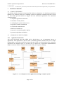
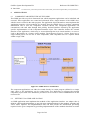
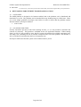
2.2.1 Application Framework
Any system developed using the GSDK will be divided into a set of components known as
applications. Each application is derived from a standard application interface that uses a simple
design pattern to create the essential base objects that provide the core functionality of the component
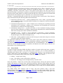
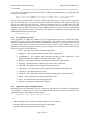
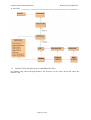
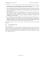
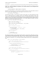
application. The diagram Figure 2-1 in shows how a complex set of application implementations
might be created to model a command and control facility for a logistics company.
Figure 2-1 – An example of a set of applications forming a complete system
Page 6 of 42
Graffica System Development Kit
Reference GL/GSDK/TN/2
21 June 2004
D:\Continuus\ccm_wa\ino\eDEP_Documentation-2004A\eDEP_Documentation\guides\eDEP_DevelopersGuide.doc
The diagram illustrates components providing a situation display (HCI), where a controller will sit at
a graphical terminal and feed vehicle and driver assignment requests to a vehicle and driver
scheduling component, which then creates a route plan for that request. The route may then be
monitored through a combination of predictive positioning and information from automatic position
detection sensors (GPS perhaps) or position reports from the driver. These positions are correlated and
reported back to the displays to give a continuous view of the current situation.
Typically, a component application will provide a key function of the overall system. These functions
may be characterised by the following functional classifications:
¾ simple data repository server – usually populated from a file or URL, it provides simple
access methods to retrieve essentially unprocessed data (for example the Vehicle Performance
Server from Figure 2-1);
¾ information management server – often a complex server collecting raw or partially processed
information, then correlating, collating, cross referencing and distributing the processed
information (for example the Correlation Engine);
¾ information routeing server – provides the ability to route information bearing messages
between client components, according to implementation dependent rules and the information
held in the messages (the Vehicle and Driver Scheduler);
¾ algorithmic server – provides a service dedicated to performing a specific calculation,
generally converting a single set of input data into a single set of output data (the Position
Prediction Engine or the Route Planning Service);
¾ HCI client – usually graphical in nature, the HCI client proves man-in-the-loop access into the
simulation engine (the Situation Display).
The application framework provides access to the generic objects that control the interface to a
component the ComponentController, the data management within the component (the Scenario) and
any graphical interface required by a client component (the AwsPanelManager). The diagram below
shows the abstract internals of a typical component, and illustrates how these objects form the core
functionality of any GSDK application:
2.2.2 Entity Models
A system developed using the GSDK will define a number of scenario object types know as entities.
Typically an entity will model a real world object, like an aircraft, a car or a radio transmitter, or
something more abstract like a message in a communications network or an interaction between
objects. Each object is an implementation of the GSDK Entity interface. This provides the basic
abstraction of any modelled entity, which must exhibit the following key features:
¾ identity – a simple name string;
¾ state – the collective values of the object’s attributes;
¾ behaviour – the changes in state brought about by external events.
Each entity defines a simple life cycle that takes it through creation, start-up, the option of regular
updates and response to external events, and finally destruction. When an entity changes state it can
raise an EntityChangeEvent, with a key name identifying the attribute (or attributes) that has changed.
Other objects can then register interest in a specific change event, so they can be notified whenever
the required change occurs.
The GSDK defines three primitive types of entity. The most primitive entity is the basic
implementation of the Entity interface, EntityImpl. This defines an object with minimal behaviour.
The next defines an object with position, the PositionedEntity. The final primitive entity type is the
MobileEntity, which defines an object whose position is constantly evolving.
Page 7 of 42
Graffica System Development Kit
Reference GL/GSDK/TN/2
21 June 2004
D:\Continuus\ccm_wa\ino\eDEP_Documentation-2004A\eDEP_Documentation\guides\eDEP_DevelopersGuide.doc
Entities of a given type are collected together into an EntityManager object. This is essentially a list,
with additional methods to create and destroy entity instances of the class defined by the manager, and
to access the entity objects held in the list either by name, or by iterating through all the entities in the
list. The entity managers are collected together under an EntityController object. Each Scenario
implementation object contains one entity controller instance.
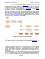
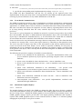
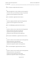
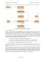
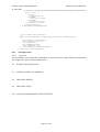
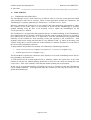
The diagram in Figure 2-2 shows the relationships between the entity types and the entity
management classes. It shows how all entity classes are derived from the Entity interface, including
the GSDK provided implementations for the positioned and mobile entity objects. The diagram also
shows how entities are collected together into sets identifying distinct object types in an
EntityManager, and how EntityManager objects are collected into a single EntityController object
contained in a Scenario (often described as the entity database).
Figure 2-2 – Entity Management Class Relationships
The layer of classes at the bottom of the diagram (the Consignment, FreightDepot, Address and
FreightVehicle classes) provide examples of user implementations of the GSDK entity primitives.
These will define user specific attributes and behaviour, and will be managed in corresponding entity
manager instances held in the Vehicle Database object derived from the abstract ScenarioImpl .
2.2.3 Distributing The Entity Objects
An entity may be referenced in some form from any of the components in a system during the lifetime
of that entity. The entity’s birth and death will usually be controlled from a single server, which has
ultimate responsibility for that entity’s existence. An entity can be referenced from a component by
subscribing to a service that will maintain the entity’s state (or at least a subset of its state) within that
component’s entity database. The service will be responsible for updating the state of the entity
reflecting the state in the remote component. An entity may be truly polymorphic, providing a
common interface across the platform, but exhibiting component specific behaviour in its local
implementation.
A server component offers a service that will maintain one or more entity classes that implement the
interfaces for which the service was defined. Also, a given entity may be updated through more than
one service if that entity implements the corresponding entity interfaces. By accessing the entity
Page 8 of 42
Graffica System Development Kit
Reference GL/GSDK/TN/2
21 June 2004
D:\Continuus\ccm_wa\ino\eDEP_Documentation-2004A\eDEP_Documentation\guides\eDEP_DevelopersGuide.doc
implementation through its interface the service can maintain any number of different entity
implementation types.
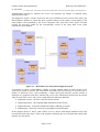
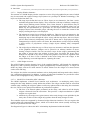
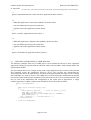
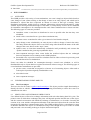
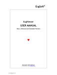
The diagram in Figure 2-3 below shows how the server maintains its local version of the entity, and
then distributes updates to clients that have registered interest in the entity by subscription to the
entity update events published by the server component. The client side service object will then
perform the necessary update on the corresponding version of the entity held in the client
component’s local database.
Figure 2-3 – Distribution of Entity Data through the System
To illustrate an entity’s polymorphism, consider a simple example where an entity models a real
world object called an aircraft. The information held within the aircraft object is accessed from a
number of different servers, each performing a distinct processing function, and the aircraft is
displayed in a graphical client HCI, which needs access to the information produced for the aircraft
entity by each of the servers. The servers might define the following functions:
¾ flight plan creation – the basic route plan for the aircraft
¾ flight management – the compiled flight information for the aircraft
¾ flight monitoring – determines whether the flight is adhering to its plan
¾ flight display – shows the aircraft on a geographical situation display
In the diagram shown in below, each of these servers is shown with sample attributes held in the
associated aircraft entity object. Each of the interfaces reflecting the server function that realises that
interface are also shown.
Page 9 of 42
Graffica System Development Kit
Reference GL/GSDK/TN/2
21 June 2004
D:\Continuus\ccm_wa\ino\eDEP_Documentation-2004A\eDEP_Documentation\guides\eDEP_DevelopersGuide.doc
2.2.4 Configuring The System Using Resources
A powerful feature of the GSDK is the ability to configure both the parameterised characteristics and
the behaviour of the system by using resource parameters to substitute the values into the run-time
environment. The resources comprise a set of primitive functions to provide access to the following
types of parameter from the code:
¾ Boolean – values of TRUE or FALSE (case insensitive);
¾ Integer – values defined by a signed 32 bit integer;
¾ Real – values defined by a 64 bit double precision number;
¾ String – a double quoted string “any string value”;
¾ List – an arbitrary bracketed sequence of values, including nested lists.
The string parameter type can be used to introduce new behaviour into the system, by using Java
Reflection to load the class identified by the class path name in the string into the running class loader
in the Java Virtual Machine. This enables instances of the class to be created, and methods in the class
to be invoked even though the class has never been directly referenced from the software. In order for
the code to make sense of the generated class, it will implement an interface whose meaning is well
understood even if the resultant behaviour is undefined.
This feature is used to introduce new entity types into the system, and can be used to configure
graphics objects or substituting new algorithms or management objects. The COMPONENTS
resource, for example, defines the list of components to be run in the system configuration,
associating the component name with the class that defines the component application. Thus the
system components and their interactions and behaviour are configured at run time, rather than being
hard coded at compile time as is the case with conventional languages.
2.2.5 Constructing Scenarios Using The Parser Framework
A component may receive its information from other server components, or it may read its data from
a file or a URL. The read is performed as a two-pass process. The first pass will read the entity objects
and their attributes from the input stream. The second (and subsequent) passes attempt to resolve any
references to other entity objects referenced from the subject entity. This two-phase process allows
forward or mutual references to be made between objects in the database.
The parser framework requires the user to set up a scenario reader object for the component, which
will attempt to read the entity definitions from the identified scenario file, by invoking the read
method on the entity’s parser class. The parser class is identified through a standard class name
comprising the name of the entity concatenated with the text “Parser”, and a standard class path. Java
reflection is then used to create the required parser object instance, and then to create the entity itself.
To summarise, the user must provide the following to read entity scenario data from a file:
¾
define the path name of file to be read in resource component.SCENARIO
¾ define the scenario reader in resource component.SCENARIO_READER – for simple text files,
this is usually set to the default reader “gsdk.scenario.ScenarioReaderImpl”
¾ provide the entity parser implementations for the required entity types in the package
component.parser.standard.
Page 10 of 42
Graffica System Development Kit
Reference GL/GSDK/TN/2
21 June 2004
D:\Continuus\ccm_wa\ino\eDEP_Documentation-2004A\eDEP_Documentation\guides\eDEP_DevelopersGuide.doc
¾ provide the corresponding entity implementation in package component.entity.
The GSDK will then automatically read the file, by picking up the required parser class
implementation for the given entity object. It will populate the entity database with the parsed entities,
resolving any forward references to any entities defined later on in the file.
2.2.6 Event Based Communications
The GSDK environment provides a range of mechanisms to facilitate asynchronous communication
between the running objects. In particular, mechanisms exist to pass messages between component
applications, to schedule future events in real time or simulation time and to notify interested objects
that some event has fired. Objects can respond to an event, either by registering interest in the event,
or by being directly referenced from the event, with the object being serviced as the event is
processed.
The events on a given component are scheduled or queued in a central event repository object called
the event scheduler. This object is defined inside the entity database object. The events added in this
object may be scheduled for immediate delivery, or for some future time. Events that are scheduled
for some future time can be cancelled, while immediate events cannot be cancelled.
Events are also used to carry information in messages between components. First, the clients that have
an interest in a message from a server must register interest by subscribing to that particular event.
The server may offer a simple event filter on the subscription so that only the required subsets of
events are received on the client. When a server wishes to signal the availability of a new piece of
information, the server component will generate an external event (which is simply a serialised form
of the general event object). This event may then be delivered through the Java RMI to the subscribed
client components.
The following list provides a summary of available event mechanisms.
¾ private event, scheduled to fire immediately – user specific implementation of the event
process method to perform any object specific processing using the event’s user defined
attributes;
¾ private event, scheduled for future simulation time – same as immediate event;
¾ private event, scheduled for future real time – same as immediate event, based on swing
timer event;
¾ public event notification, scheduled to fire immediately – user specific event
implementation, event consumer registers interest in event through event scheduler;
¾ public event notification, scheduled for future simulation time – same as immediate event
notification;
¾ public event notification, scheduled for future real time – same as immediate event
notification, based on swing timer;
¾ inter-component event notification – user specific implementation, serialised event
transmitted through middleware.
2.2.7
Situational Graphics Displays
2.2.7.1 Overview
The graphics facilities provided by the GSDK are designed to allow the user to develop a graphical
view of the information evolving in a client database. The GSDK graphics facilities are built above
the Java Swing classes, enabling the GSDK graphics to be used inside Swing container objects. The
GSDK graphics manager objects provide their own display painting mechanisms that respond to
requests from GSDK graphical objects or from external sources to redraw or to reformat (perhaps
changing the object shape or size) prior to redraw.
Page 11 of 42
Graffica System Development Kit
Reference GL/GSDK/TN/2
21 June 2004
D:\Continuus\ccm_wa\ino\eDEP_Documentation-2004A\eDEP_Documentation\guides\eDEP_DevelopersGuide.doc
2.2.7.2 Display Window Structure
The structure of a GSDK display window comprises a series of logical graphical layers some of which
may be associated with a physical image object (known as a pixmap in X Window terminology). The
layers are divided into three sets.
¾ The map layers define the base set. These layers are not interactive, but form a static,
scaleable background for the display. They can define a 2D map of arbitrary complexity,
where objects defining terrain contours, areas, linear features or point features may be
represented. The maps are not restricted to conventional geographical plans, but can
define any 2D representation of a given data set. The layers can be used to divide the
displayed objects into selectable groups, allowing the user to control the content of the
map by selecting the layers to be displayed.
¾ The transparent overlay layers define the middle set. These layers are not interactive, but
allow the user to draw objets in colours that are modified to allow the features of the
underlying map to show through the object. Along with the map layers, this set of layers
will be drawn relatively infrequently, and will be drawn onto a single physical image.
Transparent layer objects come in two forms, the monochrome overlays (objects defining
a single colour) or polychrome overlays (single objects defining many transparent
colours).
¾ The widget layers define the top set. These layers are interactive and form the dynamics
of the graphical interface. Widgets can be placed in an arbitrary number of layers,
forming a simple z-buffer. The user can select a layer for the widget, guaranteeing that
the widget is always above the widgets in lower layer, but below the layers above.
Widgets can respond to any mouse or keyboard graphics events that are signalled when
the widget is in focus. Focus is defined as the cursor being above the widget, or the
widget behaving as a modal input device, capturing all events.
2.2.7.3 AWS Widget Overview
The AWS Widgets form the dynamic basis of the graphical interface. AWS stands for Alternative
Widget Set, and is primarily designed to support geographically orientated displays. A widget can
define any shape, and can be made sensitive to mouse motion over the widget or to mouse actions
such as click and drag.
The widgets also define conventional attributes such as background and foreground colour, shadow,
size, transparent background. In addition, a variety of behavioural attributes are provided to allow
features such as highlight on entry, and user defined behaviour.
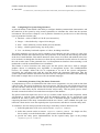
2.2.7.4 Model View Controller (MVC) Structure
The GSDK implements a Model-View-Controller style architecture. An underlying entity object,
managed in the entity database, usually defines the models. The widget can then form an association
with the entity, enabling the widget to update to reflect any updates made to the entity; this constitutes
the view. There are two principle mechanisms to perform these updates.
¾ The first is an internal update performed on the entity, and echoed to all the display
widgets referenced from the association. This provides a simple mechanism to update
widgets on a regular basis.
¾ Alternatively, the widget can register interest in the entity change events published by the
entity class. In this case the widget only updates when the entity changes its state.
The controller aspects are supported by abstracted widget behaviour interfaces. The user registers the
required behaviour implementation classes, which are invoked when actions (usually involving the
mouse) are performed over the widget.
The diagram in Figure 2-4 shows the MVC relationships implemented within the GSDK:
Page 12 of 42
Graffica System Development Kit
Reference GL/GSDK/TN/2
21 June 2004
D:\Continuus\ccm_wa\ino\eDEP_Documentation-2004A\eDEP_Documentation\guides\eDEP_DevelopersGuide.doc
Figure 2-4 - Widget Model-View-Controller Structure
2.2.8 Geometric Algorithms
A number of geometric facilities are provided in the GSDK to support both algorithm development,
and the graphics processing. The package defines a set of double precision position types (Point2D
defining Cartesian x and y, Point3D adds z to 2D, Point4D adds time to 3D and Position defines
additional fields for heading, speed and rates of change of altitude and turn). In addition the geometric
utilities
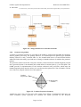
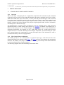
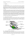
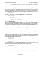
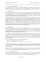
The geometric utilities also define a Projector interface, which transforms a latitude/longitude position
into a general 2D plane. Conventionally this would define a Cartesian point (x, y) on a flat plane. The
GSDK provides an implementation of the Lambert conformal conic projection, which maps the
latitude/longitude points onto the surface of a cone that cuts the spheroid on a line of latitude, with the
axis of the cone, aligned with the axis of the spheroid.
N
Lambert
Projection Cone
Intersecting
Latitude
S
Figure 2-5 - Lambert Projection Geometry
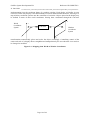
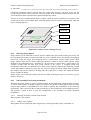
Another key class is the Converter class. This simple object defines a transformation that maps any
world coordinate system (typically the Cartesian 2D system provided by the Projector
Page 13 of 42
Graffica System Development Kit
Reference GL/GSDK/TN/2
21 June 2004
D:\Continuus\ccm_wa\ino\eDEP_Documentation-2004A\eDEP_Documentation\guides\eDEP_DevelopersGuide.doc
implementation) into the coordinate frame of a graphics window. Each display will define its own
Converter, which may display scales differentially in vertical and horizontal directions, allowing it to
map arbitrary coordinate systems onto the constraints of a window. Objects placed in the display may
be defined in terms of their world coordinates. Passing these coordinates through the Converter
World
Coordinate
System
x
v
Converter
u
Window
Coordinate
System
y
transformation automatically places and scales the object accordingly. Centralising control of the
centre and scale of a display allows straightforward manipulation by the user when the view needs to
be changed or modified.
Figure 2-6 - Mapping from World to Window Coordinates
Page 14 of 42
Graffica System Development Kit
Reference GL/GSDK/TN/2
21 June 2004
D:\Continuus\ccm_wa\ino\eDEP_Documentation-2004A\eDEP_Documentation\guides\eDEP_DevelopersGuide.doc
3
3.1
FUNDAMENTALS
GSDK ARCHITECTURE
Page 15 of 42
Graffica System Development Kit
Reference GL/GSDK/TN/2
21 June 2004
D:\Continuus\ccm_wa\ino\eDEP_Documentation-2004A\eDEP_Documentation\guides\eDEP_DevelopersGuide.doc
4
CONFIGURATION
Page 16 of 42
Graffica System Development Kit
Reference GL/GSDK/TN/2
21 June 2004
D:\Continuus\ccm_wa\ino\eDEP_Documentation-2004A\eDEP_Documentation\guides\eDEP_DevelopersGuide.doc
5
COMPONENT MODEL
Page 17 of 42
Graffica System Development Kit
Reference GL/GSDK/TN/2
21 June 2004
D:\Continuus\ccm_wa\ino\eDEP_Documentation-2004A\eDEP_Documentation\guides\eDEP_DevelopersGuide.doc
6
APPLICATIONS
6.1 COMPONENT ARCHITECTURE OF THE GSDK
The GSDK provides a top-level framework into which component applications can be initialised and
executed. These applications are created and referenced from a single instance of the GSDK class,
which in turn is created in the main program. The application objects themselves must implement the
Application interface, whose methods are invoked from the GSDK object to perform component
initialisation and to start the component execution thread. The component applications can
communicate with each other through their publicly declared interface defined by the application
specific implementation of the ComponentController object. The controller defines the external
interface of the application, which may be accessed through the local virtual machine, or across a
LAN or the Internet on a remote virtual machine. The diagram in Figure 6-1 below shows how a
single GSDK process can run one or more components; each component runs on a separate thread
within a single JVM.
Figure 6-1 GSDK Process Architecture
The component applications can either be created directly in a main program (defined in a simple
static class) or the applications can be created using Java Reflection to construct the required
component objects from class definitions provided in a list resource called COMPONENTS in the
resources file.
6.2 SETTING UP A GSDK APPLICATION
A GSDK application must implement the methods of the Application interface. An adapter class is
defined, called ApplicationAdapter, to provide empty implementations for the methods, returning null
values where required. The implementation class can then provide the initialisation processing
required for the given component by providing implementations of the methods described in section
Page 18 of 42
Graffica System Development Kit
Reference GL/GSDK/TN/2
21 June 2004
D:\Continuus\ccm_wa\ino\eDEP_Documentation-2004A\eDEP_Documentation\guides\eDEP_DevelopersGuide.doc
6.2.2 below. The implementation class must then be added to the GSDK class by invoking the static
addApplication method.
public static void addApplication( Application application, String componentName )
public static void addApplication( String className, String componentName )
The first of these methods adds an already existing application object, together with its component
name, to the GSDK process. The second method is passed the className of the object (defined using
the full class path from the code base), with the component name. The method then uses Java
reflection to construct an application object of the type referred to by the class path. All the required
components must be added using either of these methods before the system can start its initialisation
sequence, and to enter the main processing loop. This sequence is entered by invoking the following
GSDK method from the main program:
gsdk.startToolkit()
6.2.1 The Application Context
As the application is added, the GSDK sets up an ApplicationContext object, which holds public
references to the key objects that comprise an application. The context object is passed into the
application initialisation methods, which use the information contained in it, and will return references
to created objects whose references will be placed in the context by the GSDK object. As the
application initialisation progresses, these key object references are assigned into the context object.
These key objects are described below:
¾ name – the name string of this component application;
¾ parameters – the external parameters supplied for this application;
¾ panelManager – the graphics panel manager provided for this application. If the
application requires no graphics, the value of this object is null;
¾ database – the scenario database containing this application's entity objects;
¾ mapping – the map manager containing any maps for this application;
¾ simClock – the simulation time manager for this application;
¾ latLongConv – the spherical to Cartesian projection method for this application;
¾ application – the application object itself;
¾ controller – the component controller defining the application's external interface;
¾ thread – defines the thread on which the application runs;
¾ status – the initialisation status of this application;
¾ graphics – the graphics update model required;
6.2.2 Application Method Implementations
Immediately after the application object is constructed, and added to the GSDK, the application’s
create method is invoked to allow any user defined initialisation processing to be performed. The
ApplicationAdapter class defines an empty method
public void create( ApplicationContext context )
/**
* When the application is registered with the middleware, this method is
* invoked to allow any user defined processing to be performed.
* @param context the application context details.
Page 19 of 42
Graffica System Development Kit
Reference GL/GSDK/TN/2
21 June 2004
D:\Continuus\ccm_wa\ino\eDEP_Documentation-2004A\eDEP_Documentation\guides\eDEP_DevelopersGuide.doc
*/
public void register( ApplicationContext context );
/**
* When the application is ready to initialise itself, this method is
* invoked to allow any user defined processing to be performed.
* @param context the application context details.
*/
public void initialise( ApplicationContext context );
/**
* reads any mapping information required by this application.
* @param context the application context details.
*/
public void readMapping( ApplicationContext context );
/**
* provides a reference to the scenario object for this application,
* defining the data model used by this application.
* @param context the application context details.
* @return the scenario data model for this application.
*/
public Scenario createDatabase( ApplicationContext context );
/**
* provides a reference to the controller object for this application,
* defining the interface to this application.
* @param context the application context details.
* @return the component controller for this application.
*/
public void createGraphics( ApplicationContext context );
/**
* provides a reference to the controller object for this application,
* defining the interface to this application.
* @param context the application context details.
* @return the component controller for this application.
Page 20 of 42
Graffica System Development Kit
Reference GL/GSDK/TN/2
21 June 2004
D:\Continuus\ccm_wa\ino\eDEP_Documentation-2004A\eDEP_Documentation\guides\eDEP_DevelopersGuide.doc
*/
public ComponentController createController( ApplicationContext context );
/**
* When the application is started, this method is invoked to allow
* any user defined processing to be performed.
* @param context the application context details.
*/
public void start( ApplicationContext context );
/**
* When the application is shutdown, this method is invoked to allow
* any user defined processing to be performed.
* @param context the application context details.
*/
public void shutdown( ApplicationContext context );
6.3 CREATING AND RUNNING A GSDK PROCESS
The following examples show how a GSDK process can be initialised with one or more component
applications running on separate threads within the single virtual machine. Each example defines the
required main method.
The first example shows how a simple system with a single application can be created. Notice that the
first statement creates the middleware discovery server. This provides the lookup/discovery
functionality that allows the application to search for other applications that it might wish to exchange
data with either as a client or a server. The GSDK object is created using the command line arguments
passed to the main method. These arguments will be parsed to provide a set of system parameters, that
may be used in the initialisation and configuration of the system and its applications. A single
example application is added, with the name EXAMPLE, before the toolkit is started.
public class ExampleMain
{
public static void main( String[] args )
{
try {
DiscoveryServer.main(null);
// create the discovery server
GSDK gsdk = new GSDK( args );
gsdk.addApplication( new DefaultApplication(), "EXAMPLE" );
gsdk.startToolkit(); }
catch ( Exception e ) { e.printStackTrace(); };
} // End method main
} // End class ExampleMain
Page 21 of 42
Graffica System Development Kit
Reference GL/GSDK/TN/2
21 June 2004
D:\Continuus\ccm_wa\ino\eDEP_Documentation-2004A\eDEP_Documentation\guides\eDEP_DevelopersGuide.doc
7
7.1
ENTITY DATABASE
STORING REAL WORLD OBJECT MODELS
7.1.1 Overview
When a developer is designing the set of application components that will make up the completed
system, he needs to develop an OO model that identifies the primary modelled objects of the system.
Within the GSDK these objects are known as entities, and will provide analogues of the real world
objects the system is designed to model. In the air traffic control domain, entity objects might be used
to represent real world items such as flights, airspace beacons, airways, sectors and conflicts. In the
military command and control domain, entity objects might represent tanks, missiles, transmitters,
command posts or data link messages.
The GSDK defines a common generic mechanism to store the modelled entities. Each component
application defines a central storage object known as a Scenario or database, which holds sets of
objects of the same type in a set of entity managers. Where the same object is used within different
component applications (for example an ATC flight might appear in a Flight Data Processor
component and in a Controller Working Position display component), the data defining the object
type is passed between the components in an entity description object. This information is used to
reconstruct the entity in the receiving application.
7.1.2 The Generic Entity Architecture
The GSDK provides a set of abstractions of a general object type, each built from the basic
abstraction defined in an interface called Entity. The Entity provides object identity and management
functions. The identity of an entity is defined by a name string, and a unique serial number allocated
to each created entity object. Further interfaces
The following diagram shows the relationships between the basic
Page 22 of 42
Graffica System Development Kit
Reference GL/GSDK/TN/2
21 June 2004
D:\Continuus\ccm_wa\ino\eDEP_Documentation-2004A\eDEP_Documentation\guides\eDEP_DevelopersGuide.doc
7.2 USING ENTITY INTERFACES TO DISTRIBUTE TYPES
By defining entity objects through interfaces, the developer can use entity objects that satisfy the
interface, and
Page 23 of 42
Graffica System Development Kit
Reference GL/GSDK/TN/2
21 June 2004
D:\Continuus\ccm_wa\ino\eDEP_Documentation-2004A\eDEP_Documentation\guides\eDEP_DevelopersGuide.doc
8
GRAPHICS
8.1 INTRODUCTION
The GSDK has been designed to support a range of graphical functions in support of geographical
situation displays. Typically a situation display will show the disposition of the objects modelled in a
given simulation facility, displayed as user definable symbols over a map. The GSDK provides a
dedicated panel class, derived from the Java Swing JPanel, called the AwsPanel. The AwsPanel
enables the developer to create a set of arbitrarily complex layers, starting with a background map,
transparent overlays and a set of widget layers, displaying widgets derived from the base widget class
AwsWidget.
The GSDK has been designed to support widgets that display user defined symbols, with
accompanying text data blocks called labels. These labels can be attached to the associated symbol
through an optional leader line. This assembly of widgets provides a standard pattern for the display
of an underlying modelled entity object, positioned on the screen at the corresponding geographical
position defined by the entity. As the entity position is updated according to its motion model, the
corresponding symbols will move on the associated displays. The GSDK does not, however, provide a
full set of conventional rectangular widgets and associated functionality, as these will be provided by
the heavyweight Java AWT or the lightweight Java Swing libraries. The GSDK does provide a
limited selection of container objects, which can be used to create columns of widgets to form a popup column menu, and it supports a configurable frame object, which provides a limited range of
nested window functionality similar to the Swing JInternalFrame class.
8.2 CREATING DISPLAY WINDOWS
The AwsPanel provides the foundation for all the primary display windows of a system developed
using the GSDK graphics facilities. The AwsPanel extends the Java swing component JPanel, and
offers multiple image buffer display management, to support the display of infrequently updated maps
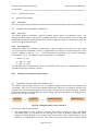
and transparent overlays and the more frequently updated widget layers. The user can configure the
panel to use as many logical layers
widget
images
mapping
images
{
BAW821
top widget layer
KLM112
bottom
widget layer
{
transparent
layers
map layers
Figure 8-1 AwsPanel Image Buffer Management
8.2.1 Adding Graphical Layers To The Display
Layers may be added to a display either explicitly by defining a layer in the display’s layer manager,
or implicitly when adding an object. The layers form a logical z-buffer ordering of the display objects.
The bottom set of layers defines any background mapping and although scaleable, it is not interactive,
and is the least often drawn part of the display. Above the map is an optional set of logical layers
Page 24 of 42
Graffica System Development Kit
Reference GL/GSDK/TN/2
21 June 2004
D:\Continuus\ccm_wa\ino\eDEP_Documentation-2004A\eDEP_Documentation\guides\eDEP_DevelopersGuide.doc
containing transparent objects, derived from the AwsOverlay interface. The map layers and the
overlay objects must be drawn using the colours provided in the AwsPalette object processed by the
AwsTransparencyFilter to produce the required transparency effects.
The top set of layers contains the interactive widgets, which are used to build the user interface to the
system. These layers can be added either when the display panel is created, or dynamically when the
layer is actually required.
MENUS
ROUTES
AIRCRAFT
AIRSPACE
Figure 8-2 Creation of a Set of Widget Layers
8.2.2 Allocating Image Buffers
Image buffers may be allocated to specific layers to enhance the speed of the redraw processing. The
user can define the number of images allocated in a given AwsPanel object, but typically any mapping
layers will occupy one image, the transparent layers a second image, and the widget layers a third
image. Simple maps may be drawn sufficiently quickly to share an image buffer with the image
defined by the transparent layers. Alternatively, all layers may be drawn onto a single image. For
example, consider that the map layer group consists of two layers. A complex terrain map
background, which takes a significant time to draw, and a relatively simple map comprising overlaid
objects that might be filtered on object type. By using two images, when the simple layer is updated,
the complex map will be copied as an image onto the simple layer’s image, onto which the filtered
objects can then be drawn.
Image buffers can be allocated explicitly by the user when defining the layers to be used by a given
display. The layers
8.2.3 Understanding The Drawing Mechanism
When the developer wishes to create a complex display, incorporating maps and transparent overlays,
as well as large numbers of display widgets, the speed of any update to the graphics screen becomes
critical, and a number of algorithms have been used to optimise the performance of the redrawing
mechanisms. This section provides a short introduction to the complexities of the update processes,
and provides a guide to how to tune the configuration of an AwsPanel to provide optimised
performance.
8.2.3.1 Drawing The Panel Contents From Scratch
When a panel is first created
8.2.3.2 Widget Layer Updates
Most updates will be performed in the widget layers, and will generally require a minimum of
Page 25 of 42
Graffica System Development Kit
Reference GL/GSDK/TN/2
21 June 2004
D:\Continuus\ccm_wa\ino\eDEP_Documentation-2004A\eDEP_Documentation\guides\eDEP_DevelopersGuide.doc
8.2.3.3
8.3
Choosing The Layers
DISPLAYING MAPS
8.3.1 Overview
The lowest group of layers defined on a panel are reserved for the display of static map information.
8.4
ADDING TRANSPARENT OVERLAYS
8.4.1 Overview
The GSDK graphics architecture supports graphical objects drawn in transparent colour. The
transparent colour effect is achieved by combining the object’s colour with the colours forming the
background immediately underneath the object. These background colours are modified to reflect the
colour tint of the transparent object.
8.4.2 The Algorithm
Transparent colours are calculated by determining a simple weighed average colour for each of the
red, green and blue components of the net background colour and the overlaid transparent colour.
Given a weighting α, where 0 <= α <= 1, and a background colour RGB (rb, gb, bb) and a transparent
colour RGB (rt, gt, bt), the combined colour components are calculated as:
rc = αrb + (1 − α )rt
g c = αg b + (1 − α ) g t
bc = αbb + (1 − α )bt
The algorithm that calculates the RGB of the combined colours may be re-implemented should a
specialist transparency effect be required.
8.4.3
Defining A Transparent Colour Palette
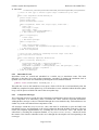
8.5 INTRODUCTION TO THE AWS WIDGET SET
The GSDK AWS package defines a set of graphical widgets derived from the abstract class
AwsWidget. This class is derived from further abstractions called the AwsWindow and the most
primitive class the AwsManagedObject. Each widget can form its own widget hierarchy, defining
child widgets that are contained inside the parent widget. The following simple class diagram shows
how this set of classes is related:
Figure 8-3 Widget Primitive Class Structure
All derived widget objects comprise:
a) The WidgetObserver class defines an interface that allows an Entity to form a decoupled
relationship with a set of widgets that are showing some aspect of the Entity graphically. These
widgets are linked through an Association object stored in the entity, which contains a list of
references to WidgetObserver objects. This allows actions that effect all the widgets related
Page 26 of 42
Graffica System Development Kit
Reference GL/GSDK/TN/2
21 June 2004
D:\Continuus\ccm_wa\ino\eDEP_Documentation-2004A\eDEP_Documentation\guides\eDEP_DevelopersGuide.doc
through the Entity to be performed through a simple mechanism. In particular, update, highlight
and destruction can be synchronised through the use of the Association object.
b) The AwsManagedObject class implements the WidgetObserver interface and provides the basic
references to the key objects that are responsible for the management of the widget. These include
updates, reformatting and draw operations, as well as the management of the z-buffer location of
the widget in its layer.
c) The AwsWindow extends the AwsManagedObject class, and provides location and size
functionality for the widget. In particular, it provides position in both window coordinates and
world coordinates, and the size/bounds of the object as a bounding rectangle in window
coordinates. It also provides basic appearance information identifying a background and
foreground colour for the widget.
d) The AwsWidget extends the AwsWindow class, and provides the behavioural elements of a
widget. It defines lists containing the mouse and keystroke listener objects to be invoked when
actions are performed over the widget. It also provides auto-repeat functionality, and the
mechanisms required to link a widget symbol to a second label widget containing some
identification information for the symbol, connected through a leader line object.
Each of these classes and the services they offer is described in more detail in the following
paragraphs.
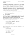
8.5.1
AwsManagedObject class
8.5.1.1 Overview
The managed object class provides the primitive from which all widgets are derived. As the name
suggests, the managed object provides links to the management and support objects that need to be
referenced by the derived graphical widget, and maintains references to the widget from external
objects. The following diagram shows the relationships between the widget management objects and
the AwsManagedObject class.
Page 27 of 42
Graffica System Development Kit
Reference GL/GSDK/TN/2
21 June 2004
D:\Continuus\ccm_wa\ino\eDEP_Documentation-2004A\eDEP_Documentation\guides\eDEP_DevelopersGuide.doc
Figure 8-4 Widget Management Structure
8.5.1.2 Widget Creation
When a widget is created, the fundamental object management references defined in the
AwsManagedObject must be initialised before the appearance and behaviour of the widget can be set.
The widget creation mechanism is thus a two-stage process; the widget is first constructed using a
parameterless constructor, and then after the required references have been set, the parameterless
validate method is invoked to complete the widget creation process. Generally the validation will
define the widget size, appearance and behaviour, using facilities provided by the AwsWindow and
AwsWidget classes. The fundamental references required are:
¾ a reference to the widget manager (held in the layer manager);
¾ a reference to the underlying widget entity (or null if there is no associated entity)
¾ a reference to the widget layer (or null if this widget is a child of another widget)
¾ a reference to the parent widget (or null if this widget is in a layer)
The information required to set these references is available when the widget is added either to its
layer, or to its parent widget. Once all of these references have been set, the widget can undergo
validation.
The use of parameterless constructors allows object factory methods to be employed to generate new
instances of the required widget from classes identified at run time (using Java Reflection), rather than
pre-compiled into the system. This flexibility allows graphical objects of distinct appearance and
behaviour to be substituted into the system without the need to re-code the management structures.
Widgets may also be created using convenience constructors with parameters, but these constructors
should only be used where the flexible substitution of another class is not required.
Page 28 of 42
Graffica System Development Kit
Reference GL/GSDK/TN/2
21 June 2004
D:\Continuus\ccm_wa\ino\eDEP_Documentation-2004A\eDEP_Documentation\guides\eDEP_DevelopersGuide.doc
8.5.1.3 Widget Validation
The validate method is overridden by derived widget classes to define the actual appearance, location
and behaviour of the widget. While some of these items may be set prior to widget validation, it is
safest to define most if not all of the widget configuration code in the derived validation method. The
user must have set the requisite widget manager, entity, layer and parent widget references between
construction and validation. All the required references will be set when the widget is added to its
layer or parent widget. The validation processing will not proceed without these references being set.
widget.validate()
widget.isValidated()
A typical validate method should always start by checking the initialisation status of the widget, prior
to calling the validate super class method, and then creating its own widget settings:
public void validate()
{
if ( this.isInitialised() ) {
super.validate();
// create the widget specific settings
…
} // End if the widget is initialised
} // End method validate
8.5.1.4 Widget Draw Method
The draw method is invoked to draw the widget onto the given AWT graphics context. This method is
declared final, as it must not be overridden. The draw method checks whether the widget is visible. If
it is then the abstract method drawComponent is invoked prior to calling the draw method of each of
the children of the widget. The method finishes up by invoking the abstract drawBorder method to
provide a border decoration for the widget. The implementations of the drawComponent and the
drawBorder methods in the derived widget object will use the graphics primitives provided through
the Java AWT Graphics and Graphics2D classes, to draw the widget subject to the widget attribute
settings defined.
8.5.1.5 General Access Methods
Access methods are provided to set the name of the widget. This name can be any text string, and is
only provided as an identification mechanism for the user to identify the widget.
widget.setName( String name )
widget.getName()
Each widget must belong to a widget layer. The layer that the widget is assigned to will determine
whether the widget appears above or below other types of widget. If the layer does not already exist, a
layer of that name will automatically be created.
widget.setLayer()
widget.getLayer()
widget.hasLayer()
The widget can be moved up and down within its layer by invoking the following methods:
widget.raise()
widget.lower()
All widgets must hold a reference to the widget manager object. This object holds references to each
of the logical widget layers, which in turn hold references to the widgets themselves. The widget
manager will normally be set automatically when the widget is added to its layer.
widget.setManager( AwsWidgetManager manager )
widget.getManager()
widget.hasManager()
The AwsPanel defining the display window containing the widget can be retrieved by calling the
following method:
widget.getDisplay()
If the user wishes a widget to consume all graphics events produced over the display, regardless of the
location of the mouse cursor, the widget can be set to be modal. This mechanism might be used in a
Page 29 of 42
Graffica System Development Kit
Reference GL/GSDK/TN/2
21 June 2004
D:\Continuus\ccm_wa\ino\eDEP_Documentation-2004A\eDEP_Documentation\guides\eDEP_DevelopersGuide.doc
menu, where the user must make a response before continuing. Note that only one widget can be
modal at any one time.
widget.setModal( boolean modal )
widget.isModal()
If the user wishes to retain a managed widget in the layer manager, but only to display it at certain
times, then the widget may be set visible or invisible. The widget is only drawn if the visibility flag is
set to true. By default this flag is set to true.
widget.setVisible( boolean visible )
widget.isVisible()
The user may wish to reference an arbitrary data object from the widget, and to be able to access this
object at some later time, after some action has been performed over the widget. The class defines
access methods to set and get this data object.
widget.setWindowData( Object data )
widget.getWindowData()
The widgets forming the children of a widget may be added, accessed and destroyed through a set of
mechanisms provided by the managed object. The number of child widgets managed by the object can
be retrieved, and the z-buffer order of the widgets can be set using raise and lower methods.
widget.addWidget( AwsManagedObject child )
widget.haveChildren()
widget.numberOfChildren()
widget.getWidget( int index )
widget.raiseChild( AwsManagedObject child )
widget.lowerChild( AwsManagedObject child )
Each widget provides access to simulation time and time functions through the following convenience
methods:
getTime()
getTimeManager()
8.5.2
AwsWindow Class
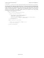
8.5.2.1 Overview
The AwsWindow class extends the AwsManagedObject to provide the basic widget position and
appearance functionality. The window class object contains attributes that define the graphical
location and rectangular extent of the widget, attributes that identify colours of background and
foreground elements of a widget and flags to indicate whether the object is transparent (that is
whether background elements are not drawn) or is highlighted.
A window can also be defined to have a “world” location, that is a 2D position defined in an arbitrary
co-ordinate frame (usually a Cartesian frame, but in principle could define any 2D system) that is
subsequently mapped into the graphics co-ordinate frame defined by the parent window panel.
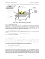
The following diagram depicts the main features of a window object.
Page 30 of 42
Graffica System Development Kit
Reference GL/GSDK/TN/2
21 June 2004
D:\Continuus\ccm_wa\ino\eDEP_Documentation-2004A\eDEP_Documentation\guides\eDEP_DevelopersGuide.doc
Conversion to
screen co-ordinates
Object in world
co-ordinate frame
Window
foreground
motif
Window background
(not drawn if
transparent)
Window
bounding
rectangle
Window
graphical
location (x, y)
height
width
Figure 8-5 The Elements of an AwsWindow Object
8.5.2.2 Setting Window Position
Window location is defined through a hierarchy of co-ordinate frames, with each frame taking its coordinate origin as an offset from its parent frame. The bounds of a widget define the graphical
Cartesian position of the widget as the top left hand corner of the bounding rectangle. The x coordinate increases moving to the right, and the y co-ordinate increases moving down the screen. The
position of the widget can be fixed by invoking the window method:
public void setLocation( int x, int y )
Alternatively the position can be set together with the bounds of the widget by invoking the following
method:
public void setBounds( int x, int y, int width, int height )
8.5.2.3
Assigning A World Position
public void setWorldLocation( double x, double y )
8.5.2.4 Setting Colours
The window defines colours for background and foreground elements of the widget. The background
colours are used to fill the area defining the widget; this area may be any shape, but will be bounded
by the window bounds rectangle. The background elements are drawn first. The foreground colours
are used to draw the motif of the widget. This motif must be drawn within the bounding rectangle, but
can overlap the background area. The motif may be drawn as text using a font, or some user defined
symbol drawn using primitive draw methods for lines, rectangles and polygons.
setBackground( Color background )
setForeground( Color foreground )
If the transparent flag is set then only the foreground elements are drawn.
setTransparent( boolean on )
The developer can also set colours using a colour function. The AwsColourFunction defines an
abstract class, which can be extended to provide implementation specific methods to determine the
colours of a widget in three different states. A ‘normal’ or ‘default’ state, an ‘active’ state, where the
widget has been activated (typically through a button press) and a ‘highlight’ state, where the widget
has focus (typically through mouse cursor entry into the widget). The colour function implementation
Page 31 of 42
Graffica System Development Kit
Reference GL/GSDK/TN/2
21 June 2004
D:\Continuus\ccm_wa\ino\eDEP_Documentation-2004A\eDEP_Documentation\guides\eDEP_DevelopersGuide.doc
might derive a colour from the current state of an entity object, or use time or position to derive a
colour. The following methods are provided to set colour functions for the background and
foreground of a window.
setBackgroundFunction( AwsColorFunction background )
setForegroundFunction( AwsColorFunction foreground )
By default, implementations of a colour function will define the active colour as the darker version of
the base colour, and the highlight colour as the brighter version of the bas colour.
Color active = base.darker();
Color highlight = base.brighter();
In the following example, a colour function is used to set the colours of a widget denoting the current
state of a traffic light entity, by changing colour as the underlying entity changes its state. The
example draws together both widget functionality and entity event functionality that will be described
further in section 9. The widget is simply updated to reflect the change of colour, and the colour is
determined by testing the Entity State, which may be one of RED, AMBER or GREEN. The traffic
light class extends the entity implementation class:
public class TrafficLight extends EntityImpl
{
public static final int RED
= 0;
public static final int AMBER = 1;
public static final int GREEN = 2;
public static final String STATE_CHANGE = “STATE_CHANGE”;
public in state = RED;
public void setState( int state )
{
boolean stateChanged = (this.state != state);
this.state = state;
if ( stateChanged )
this.notifyEntityChange( STATE_CHANGE );
} // End method setState
public int getState()
{
return state;
} // End method getState
} // End class TrafficLight
The widget class defines a simple coloured circular marker to represent the traffic light. It creates a
colour function to monitor the traffic light’s state, and an event listener to trigger the required widget
update, that will be notified when the entity changes its state. Note that the entity object is passed to
the widget in its constructor, or by invoking the setEntity method defined in the AwsManagedObject
class.
public class TrafficLightSymbol extends AwsMarker
{
// The traffic light change listener
//
public class TrafficLightChange implements EventListener
{
public void notify( EventObject e )
{
TrafficLightSymbol.this.requestUpdate();
} // End method notify
} // End method TrafficLightChange
// The traffic light colour function
//
public class TrafficLightColours extends AwsColourFunction
{
public Color getColour()
{
TrafficLight tl = TrafficLightSymbol.this.getEntity();
int state = tl.getState();
Page 32 of 42
Graffica System Development Kit
Reference GL/GSDK/TN/2
21 June 2004
D:\Continuus\ccm_wa\ino\eDEP_Documentation-2004A\eDEP_Documentation\guides\eDEP_DevelopersGuide.doc
switch ( state ) {
case RED:
return Color.red;
case AMBER:
return Color.orange;
case GREEN:
return Color.green;
} // End switch on state
} // End method notify
} // End method TrafficLightChange
// The traffic light constructor
//
public TrafficLightSymbol( TrafficLight trafficLight, AwsWidget parent )
{
this.setEntity( trafficLight );
this.setLocation(100, 200);
this.setRadius(5);
this.addWidget(parent);
this.setVisible( true );
} // End constructor TrafficLightSymbol
} // End class TrafficLightSymbol
8.5.3
AwsWidget Class
8.5.3.1 Overview
The AwsWidget class extends the AwsWindow to provide the basic widget behaviour functionality.
The widget class object contains attributes that…
8.6
WIDGET FUNCTIONALITY
8.7
ADDING LABELS TO SYMBOLS
8.8
CREATING MENUS
8.9
CREATING LISTS
8.10 ASSOCIATING WIDGETS WITH AN ENTITY
Page 33 of 42
Graffica System Development Kit
Reference GL/GSDK/TN/2
21 June 2004
D:\Continuus\ccm_wa\ino\eDEP_Documentation-2004A\eDEP_Documentation\guides\eDEP_DevelopersGuide.doc
9
EVENT MODELS
9.1 OVERVIEW
The GSDK provides a rich variety of event mechanisms. An event is simply an object which describes
some change of state (often referring to the change of state in an entity object), and which can be
distributed to objects that have expressed an interest in events of that type occurring. These
distribution mechanisms enable objects to exchange information or data between themselves, either
with the objects having mutual knowledge of each other, or anonymously. Events can be scheduled
for immediate consumption or for consumption after some future simulation time or future real time.
The following types of events are provided:
♦ immediate events: events that are distributed as soon as possible after the time they were
scheduled;
♦ timed events: events that fire at a given future simulation time;
♦ real time events: events that fire after a given interval of real-time has elapsed;
♦ entity change events: scheduled by an entity object to reflect a change of state in the entity.
The entity defines the subject of the event, and a string token identifies the nature of the state
change in the event, known as the “topic” name;
♦ update events: an event that automatically reschedules itself periodically, and executes the
“update” method on the given target updateable object;
♦ inter-component messages: these events define the serialised objects that are exchanged
between component servers running on the GSDK platform;
♦ forwarded event: a special event that re-schedules itself in order to release its processing code
from the thread it was scheduled on.
Events can either be scheduled for consumption through a central event scheduler, or will be
distributed directly to objects that have registered an interest in that event type. The following types of
event distribution mechanisms are provided:
♦ private events: events that are targeted to a known set of consuming objects. Often used to
wake-up the object that originally scheduled the event;
♦ subscribed events:
♦ inter-component messages:
9.2
UNDERSTANDING EVENT OBJECTS
9.2.1 The Event Object
The base class for all events is gsdk.events.EventObject. This object provides simple functionality to
identify the time at which it is due to “fire”, and supporting functionality to allow the event to be
scheduled in time order.
9.3 SIMULATING ASYNCHRONOUS BEHAVIOUR
User defined objects will need to exchange information with each other during their life cycles. The
points in time at which these exchanges take place will depend upon the internal state of the object,
and the external environment with which the exchange of information is to be made. Generally the
creation of an event and the subsequent notification of the interested objects that the event has been
triggered will signal these communication points. The GSDK toolkit provides a comprehensive range
of facilities that allow the objects to communicate using events, though the way he events are stored
and processed varies according to the type of object interaction required.
Page 34 of 42
Graffica System Development Kit
Reference GL/GSDK/TN/2
21 June 2004
D:\Continuus\ccm_wa\ino\eDEP_Documentation-2004A\eDEP_Documentation\guides\eDEP_DevelopersGuide.doc
9.4 THE EVENT SCHEDULER
The EventScheduler class provides a centralised mechanism to schedule events within a single
component application. The component instance of the EventScheduler is held in the component
database object derived from the abstract class ScenarioImpl defined in the package gsdk.scenario.
9.5 USING EVENTS
The toolkit offers a number of event mechanisms to support asynchronous event distribution. These
mechanisms allow the user to schedule events to trigger an immediate response, a response scheduled
for a future simulation time, or a response after an elapsed real time interval. In addition, a special
type of event, called an external event and referred to as a message, is used to transfer information
between components through a serialised RMI based interface.
It should be noted that the contents of a scheduled event should not be altered once the event has fired
and is being distributed to its components, unless the user fully understands the consequences of any
changes. The event may be distributed to many consumers, and any modification to the event
attributes may invalidate the information contained in the event. For example if a user wishes to
reschedule an event at a future time, the user should not simply change the event time with a call to
the method setTime(time), but should create and schedule a new event with the new time as a
constructor attribute. If the event time attribute is altered and a subsequent consumer accesses the time
value, the consumer could schedule events for the wrong time and forward predictions on the basis of
this time and the current state of an entity, may be calculated incorrectly.
9.5.1 Future Events
The future event mechanism enables an event to be scheduled to fire at a given future simulation time.
First, when the simulation clock reaches or passes the scheduled time, the event will be removed from
the scheduler and processed by invoking the abstract method process(). Then each registered
subscriber to the event type is notified of the event by calling the notify(event) method of each of
the event listeners provided by the respective subscribers.
A user specific event may be implemented by extending the abstract class EventObject. The user
can add arbitrary attributes and functionality to the object, but must provide an implementation of the
abstract process() method. The user must also set the time in the event, either through the event
constructor, or by invoking the setTime() method. Failure to set the simulation time in the event
will result in the time being set to a large negative number, resulting in an error being reported when
the event is scheduled.
An event is scheduled by invoking one of the following methods:
public void schedule( EventObject e );
public void scheduleAfter( EventObject e, double interval );
The first method schedules the event for the future time set in the event. The second schedules the
event after the given interval number of simulated seconds have elapsed from the current simulation
time. The time in the event is calculated by adding the current simulation time to the time given in the
interval parameter.
A future event can be cancelled at any time prior to the event firing time by invoking the method
cancel(event), which matches the given event reference with the events stored in the future event
heap, and if present, removes it from the event heap to cancel it.
9.5.1.1 Example of a Future Event
The following example shows how a future event might be used to schedule a simple radar update to
produce a sequence of plots, using the process() method to define the event behaviour. When the
event is processed, a new event is scheduled for the next predicted target illumination time.
Page 35 of 42
Graffica System Development Kit
Reference GL/GSDK/TN/2
21 June 2004
D:\Continuus\ccm_wa\ino\eDEP_Documentation-2004A\eDEP_Documentation\guides\eDEP_DevelopersGuide.doc
// Create an event type to simulate regular target illumination by the radar
//
public class TargetEvent extends EventObject
{
private Target target;
private Radar radar;
private EventScheduler events;
public TargetEvent( double time, Target target, Radar radar )
{
super( time );
this.target = target;
this.radar = radar;
this.events = radar.getEventManager();
} // End constructor TargetEvent
public void getTarget()
{
return target;
} // End method getTarget
public void process()
{
radar.calculateSignal( target );
events.schedule( new TargetEvent(time+updateInterval, target, radar) );
} // End method process
} // End class TargetEvent
// Create the plot sequence by scheduling the first target event after
// the target has been created.
//
public class NewTarget implements EventListener
{
public void notify( EventObject e )
{
TargetCreationEvent TCE = (TargetCreationEvent)e;
double time = e.getTime() + updateInterval;
TargetEvent targetEvent = new TargetEvent( time, TCE.getTarget(), radar );
eventManager.schedule( targetEvent );
} // End method notify
} // End class NewTarget
9.5.2 Immediate Events
Immediate events are created and scheduled in a similar way to simulation events. The main
difference is that they fire at the earliest opportunity, regardless of whether the simulation clock is
updated or not. The events are scheduled by invoking the event scheduler method:
public void scheduleNow( EventObject e );
This adds the event to the immediate event queue, which will fire the event immediately after the
GSDK has completed its main update loop. If an immediate event is scheduled within the main update
loop, it will be processed before the start of the next update loop.
9.5.3 Component Messages
The component messages provide the inter-component communication objects that are passed from a
server component to a subscribing client, to furnish the client with the requested information.
Although these message events are scheduled through the event scheduler, they look and behave in a
similar way to the conventional intra-component events.
All messages extend the ExternalEvent class, and must be serialisable to pass the RMI event
marshalling process, and distributed to the client components through the RMI connection. The user
creates the required implementation by extending the ExternalEvent class, and notifies the
subscribers by invoking the component method, notifySubscribers(event), which will invoke
the remote event listeners submitted to the server through the subscription call corresponding to the
event type.
Page 36 of 42
Graffica System Development Kit
Reference GL/GSDK/TN/2
21 June 2004
D:\Continuus\ccm_wa\ino\eDEP_Documentation-2004A\eDEP_Documentation\guides\eDEP_DevelopersGuide.doc
9.5.4 Real Time Events
Unlike other event types defined in the GSDK that are associated with the progress of simulation
time, real-time events fire after a given interval of actual time. Real time events are implemented
using Java Swing timers to cause the real time event to fire at the required time. They can be
scheduled through by invoking the convenience method scheduleRealTime provided by the
EventScheduler class. This defines an internal queue of real-time events, implemented by the
RealTimeEventQueue class. The user event is simply an implementation of the abstract EventObject
class.
The EventScheduler offers two methods to schedule real time events. The first method schedules a
single real-time event to fire after a given delay period given in milliseconds. The second method
schedules the first real time event to fire after the given delay in milliseconds, and subsequent events
scheduled to fire with a repeat period also defined in milliseconds.
public void scheduleRealTime( EventObject e, long delay )
public void scheduleRealTime( EventObject e, long delay, long repeatPeriod )
Real time events can be cancelled provided the user maintains a reference to the scheduled event
object, by invoking the method cancelRealTime.
public void cancelRealTime( EventObject e )
9.5.5 Entity Change Events
Entity change events provide a simple and efficient mechanism to register interest in a change
occurring to a particular entity, or to a set of entities defined within an entity manager, and be notified
when the requested change occurs. The entity will raise an internal entity change event that is only
visible to the clients that have registered with the entity or its manager. This event also contains the
identity of the type of change that has taken place, in the form of a string constant.
In the following example, an entity called “flight” is defined by an interface, which also defines the
name strings of the published entity changes. These name strings are defined as “public static final”,
as they are available to all client objects of the instances of this class.
public interface
{
public static
public static
public static
Flight extends MobileEntity
final String CHANGE_ALTITUDE = “CHANGE ALTITUDE”;
final String CHANGE_HEADING = “CHANGE HEADING”;
final String CHANGE_SPEED
= “CHANGE SPEED”;
// flight interface methods
public void setAltitude( double altitude );
public void setHeading( double heading );
public void setSpeed( double speed );
...
} // End interface Flight
The flight entity implementation provides the required change notification, when the selected
attributes have changed their value:
Public class FlightImpl extends MobileEntityImpl implements Flight
{
private double altitude;
...
public void setAltitude( double altitude )
{
double oldAltitude = this.altitude;
this.altitude = altitude;
if ( oldAltitude != altitude )
this.notifyChangeEvent( CHANGE_ALTITUDE );
} // End method setAltitude
} // End class FlightImpl
Page 37 of 42
Graffica System Development Kit
Reference GL/GSDK/TN/2
21 June 2004
D:\Continuus\ccm_wa\ino\eDEP_Documentation-2004A\eDEP_Documentation\guides\eDEP_DevelopersGuide.doc
The flight client object (that is any object that makes use of the services provided by the flight entity),
can be notified of any published change to the entity, by registering interest in the required entity
change, identified by the published entity change name string in the Flight interface. Note that the
method “registerForChangeEvent” is inherited from the MobileEntity interface. The client object
provides an event listener to the register method, which will be notified of any entity change
immediately after the change has been detected.
public class FlightClient
{
public class Action implements EventListener
{
public void notify( EventObject e )
{
EntityChangeEvent ECE = (EntityChangeEvent)e;
Flight flight = (Flight)ECE.getSubject();
String topic = ECE.getTopic();
System.out.println( “Notified of entity change for ”+flight.getName()+
” change is “+ECE.getTopic() );
} // End method notify
} // End class Action
public FlightClient( Flight flight )
{
...
flight.registerForChangeEvent( “CHANGE”, action );
...
} // End class FlightClient
} // End class FlightClient
Page 38 of 42
Graffica System Development Kit
Reference GL/GSDK/TN/2
21 June 2004
D:\Continuus\ccm_wa\ino\eDEP_Documentation-2004A\eDEP_Documentation\guides\eDEP_DevelopersGuide.doc
10 UTILITIES
Page 39 of 42
Graffica System Development Kit
Reference GL/GSDK/TN/2
21 June 2004
D:\Continuus\ccm_wa\ino\eDEP_Documentation-2004A\eDEP_Documentation\guides\eDEP_DevelopersGuide.doc
11 DEVELOPING FOR INTERNET ENABLED APPLICATIONS
11.1 OVERVIEW
The eDEP platform is designed to be Internet enabled, that is the platform can be distributed and
launched as a jar file. The platform can be launched from any desktop using Java Web Start. There
are several simple guidelines developers must follow in order to ensure that the platform remains
Internet enabled. Developers shall not:
•
scan for files.
11.2 SCANNING FOR FILES
Security restrictions prevent jar files from scanning for files, i.e. it is not possible to determine the
contents of a directory. This problem is exhibited in the ATC application launcher. When running
from a jar file it is not possible to query the file system to determine the available component tests.
Providing a file containing the list of available component tests solves this problem. The launcher is
able to read the file and determine the list of component tests.
Developers shall ensure that the system can be launched from a jar file.
Page 40 of 42
Graffica System Development Kit
Reference GL/GSDK/TN/2
21 June 2004
D:\Continuus\ccm_wa\ino\eDEP_Documentation-2004A\eDEP_Documentation\guides\eDEP_DevelopersGuide.doc
12 TIME SERVER
12.1 TIMEMANAGER UPDATING
The TimeManager object is used extensively in eDEP in order to access the system time and control
when scheduled events will be executed. When a client application includes the TimeService, the
TimeManager is regularly updated by the TimeService’s TimeNotifier object.
However, sometimes the TimeService is not wanted by the client application (presumably to reduce
the overhead of tick events where it’s not needed), in which case the TimeManager is generally
updated manually using the time of an incoming event to update the TimeManager via the
setElapsedTime method.
The TrackService is an application that performs this type of manual updating of the TimeManager.
If an application wishes to include a TrackService but also wants to start the TimeService in order to
have wakeup calls at specific times, it is important to avoid the TimeManager being updated both
manually (in the TrackService from incoming events) and regularly by the TimeService. Such
updating could lead to timing problems that are very difficult to find e.g. where an incoming event
with the wrong time is used to set the time in the TrackService, then the TimeService sets the time to
the correct value immediately afterward.
To help eliminate this problem two methods were added to the TimeManager interface.
•
void setTimeServiceUpdating(Boolean timeServiceUpdating).
•
boolean getTimeServiceUpdating()
The first method is called by the constructor in the TimeService to let the TimeManager know that it’s
being updated by the TimeService.
A client should call the second method before it manually updates the system time. If the value
returned is true then the manual updating should not be done since the clock will already have the
correct value. If the value returned is false then the manual updating may be performed.
In this way if an application includes a TrackService but not a TimeService then the TimeManager
will be updated manually. If the application adds the TimeService then only the TimeService will
update the TimeManager.
Page 41 of 42
Graffica System Development Kit
Reference GL/GSDK/TN/2
21 June 2004
D:\Continuus\ccm_wa\ino\eDEP_Documentation-2004A\eDEP_Documentation\guides\eDEP_DevelopersGuide.doc
13 CASE STUDY
Page 42 of 42