1
w w w . k e i th l e y. c o m
www.keithley.com
Model 6517B
Model 6517B
Reference Manual
Reference Manual
6517B-901-01 Rev. B / June 2009
6517B-901-01 Rev. B / June 2009
A
G R E A T E R
M E A S U R E
O F
C O N F I D E N C E
A
G R E A T E R
M E A S U R E
O F
C O N F I D E N C E
WARRANTY
Keithley Instruments, Inc. warrants this product to be free from defects in material and workmanship for a period of
one (1) year from date of shipment.
Keithley Instruments, Inc. warrants the following items for 90 days from the date of shipment: probes, cables,
software, rechargeable batteries, diskettes, and documentation.
During the warranty period, Keithley Instruments will, at its option, either repair or replace any product that proves
to be defective.
To exercise this warranty, write or call your local Keithley Instruments representative, or contact
Keithley Instruments headquarters in Cleveland, Ohio. You will be given prompt assistance and return instructions.
Send the product, transportation prepaid, to the indicated service facility. Repairs will be made and the product
returned, transportation prepaid. Repaired or replaced products are warranted for the balance of the original
warranty period, or at least 90 days.
LIMITATION OF WARRANTY
This warranty does not apply to defects resulting from product modification without Keithley Instruments’ express
written consent, or misuse of any product or part. This warranty also does not apply to fuses, software,
non-rechargeable batteries, damage from battery leakage, or problems arising from normal wear or failure to follow
instructions.
THIS WARRANTY IS IN LIEU OF ALL OTHER WARRANTIES, EXPRESSED OR IMPLIED, INCLUDING ANY
IMPLIED WARRANTY OF MERCHANTABILITY OR FITNESS FOR A PARTICULAR USE. THE REMEDIES
PROVIDED HEREIN ARE BUYER’S SOLE AND EXCLUSIVE REMEDIES.
NEITHER KEITHLEY INSTRUMENTS, INC. NOR ANY OF ITS EMPLOYEES SHALL BE LIABLE FOR ANY
DIRECT, INDIRECT, SPECIAL, INCIDENTAL, OR CONSEQUENTIAL DAMAGES ARISING OUT OF THE USE
OF ITS INSTRUMENTS AND SOFTWARE, EVEN IF KEITHLEY INSTRUMENTS, INC. HAS BEEN ADVISED IN
ADVANCE OF THE POSSIBILITY OF SUCH DAMAGES. SUCH EXCLUDED DAMAGES SHALL INCLUDE, BUT
ARE NOT LIMITED TO: COST OF REMOVAL AND INSTALLATION, LOSSES SUSTAINED AS THE RESULT OF
INJURY TO ANY PERSON, OR DAMAGE TO PROPERTY.
A
G R E A T E R
M E A S U R E
O F
C O N F I D E N C E
Keithley Instruments, Inc.
Corporate Headquarters • 28775 Aurora Road • Cleveland, Ohio 44139
440-248-0400 • Fax: 440-248-6168 • 1-888-KEITHLEY (1-888-534-8453) • www.keithley.com
3/07
Model 6517B
Electrometer
Reference Manual
©2009, Keithley Instruments, Inc.
All rights reserved.
Cleveland, Ohio, U.S.A.
Document Number: 6517B-901-01 Rev. B / June 2009
Safety Precautions
The following safety precautions should be observed before using this product and any associated instrumentation. Although some
instruments and accessories would normally be used with non-hazardous voltages, there are situations where hazardous conditions may
be present.
This product is intended for use by qualified personnel who recognize shock hazards and are familiar with the safety precautions required
to avoid possible injury. Read and follow all installation, operation, and maintenance information carefully before using the product. Refer
to the user documentation for complete product specifications.
If the product is used in a manner not specified, the protection provided by the product warranty may be impaired.
The types of product users are:
Responsible body is the individual or group responsible for the use and maintenance of equipment, for ensuring that the equipment is
operated within its specifications and operating limits, and for ensuring that operators are adequately trained.
Operators use the product for its intended function. They must be trained in electrical safety procedures and proper use of the instrument.
They must be protected from electric shock and contact with hazardous live circuits.
Maintenance personnel perform routine procedures on the product to keep it operating properly, for example, setting the line voltage or
replacing consumable materials. Maintenance procedures are described in the user documentation. The procedures explicitly state if the
operator may perform them. Otherwise, they should be performed only by service personnel.
Service personnel are trained to work on live circuits, perform safe installations, and repair products. Only properly trained service
personnel may perform installation and service procedures.
Keithley Instruments products are designed for use with electrical signals that are rated Measurement Category I and Measurement
Category II, as described in the International Electrotechnical Commission (IEC) Standard IEC 60664. Most measurement, control, and
data I/O signals are Measurement Category I and must not be directly connected to mains voltage or to voltage sources with high transient
over-voltages. Measurement Category II connections require protection for high transient over-voltages often associated with local AC
mains connections. Assume all measurement, control, and data I/O connections are for connection to Category I sources unless otherwise
marked or described in the user documentation.
Exercise extreme caution when a shock hazard is present. Lethal voltage may be present on cable connector jacks or test fixtures. The
American National Standards Institute (ANSI) states that a shock hazard exists when voltage levels greater than 30V RMS, 42.4V peak,
or 60VDC are present. A good safety practice is to expect that hazardous voltage is present in any unknown circuit before measuring.
Operators of this product must be protected from electric shock at all times. The responsible body must ensure that operators are
prevented access and/or insulated from every connection point. In some cases, connections must be exposed to potential human contact.
Product operators in these circumstances must be trained to protect themselves from the risk of electric shock. If the circuit is capable of
operating at or above 1000V, no conductive part of the circuit may be exposed.
Do not connect switching cards directly to unlimited power circuits. They are intended to be used with impedance-limited sources. NEVER
connect switching cards directly to AC mains. When connecting sources to switching cards, install protective devices to limit fault current
and voltage to the card.
Before operating an instrument, ensure that the line cord is connected to a properly-grounded power receptacle. Inspect the connecting
cables, test leads, and jumpers for possible wear, cracks, or breaks before each use.
04/09
When installing equipment where access to the main power cord is restricted, such as rack mounting, a separate main input power
disconnect device must be provided in close proximity to the equipment and within easy reach of the operator.
For maximum safety, do not touch the product, test cables, or any other instruments while power is applied to the circuit under test.
ALWAYS remove power from the entire test system and discharge any capacitors before: connecting or disconnecting cables or jumpers,
installing or removing switching cards, or making internal changes, such as installing or removing jumpers.
Do not touch any object that could provide a current path to the common side of the circuit under test or power line (earth) ground. Always
make measurements with dry hands while standing on a dry, insulated surface capable of withstanding the voltage being measured.
The instrument and accessories must be used in accordance with its specifications and operating instructions, or the safety of the
equipment may be impaired.
Do not exceed the maximum signal levels of the instruments and accessories, as defined in the specifications and operating information,
and as shown on the instrument or test fixture panels, or switching card.
When fuses are used in a product, replace with the same type and rating for continued protection against fire hazard.
Chassis connections must only be used as shield connections for measuring circuits, NOT as safety earth ground connections.
If you are using a test fixture, keep the lid closed while power is applied to the device under test. Safe operation requires the use of a lid
interlock.
If a
screw is present, connect it to safety earth ground using the wire recommended in the user documentation.
The ! symbol on an instrument means caution, risk of danger. The user should refer to the operating instructions located in the user
documentation in all cases where the symbol is marked on the instrument.
The
symbol on an instrument means caution, risk of danger. Use standard safety precautions to avoid personal contact with these
voltages.
The
The
symbol on an instrument shows that the surface may be hot. Avoid personal contact to prevent burns.
symbol indicates a connection terminal to the equipment frame.
If this
symbol is on a product, it indicates that mercury is present in the display lamp. Please note that the lamp must be properly
disposed of according to federal, state, and local laws.
The WARNING heading in the user documentation explains dangers that might result in personal injury or death. Always read the
associated information very carefully before performing the indicated procedure.
The CAUTION heading in the user documentation explains hazards that could damage the instrument. Such damage may invalidate the
warranty.
Instrumentation and accessories shall not be connected to humans.
Before performing any maintenance, disconnect the line cord and all test cables.
To maintain protection from electric shock and fire, replacement components in mains circuits - including the power transformer, test leads,
and input jacks - must be purchased from Keithley Instruments. Standard fuses with applicable national safety approvals may be used if
the rating and type are the same. Other components that are not safety-related may be purchased from other suppliers as long as they
are equivalent to the original component (note that selected parts should be purchased only through Keithley Instruments to maintain
accuracy and functionality of the product). If you are unsure about the applicability of a replacement component, call a Keithley Instruments
office for information.
To clean an instrument, use a damp cloth or mild, water-based cleaner. Clean the exterior of the instrument only. Do not apply cleaner
directly to the instrument or allow liquids to enter or spill on the instrument. Products that consist of a circuit board with no case or chassis
(e.g., a data acquisition board for installation into a computer) should never require cleaning if handled according to instructions. If the
board becomes contaminated and operation is affected, the board should be returned to the factory for proper cleaning/servicing.
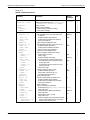
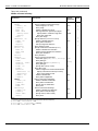
Table of Contents
Section
1
Topic
Page
Introduction ............................................................................................. 1-1
Introduction .................................................................................................
Capabilities and features overview.......................................................
Available options and accessories .......................................................
Manual addenda ..................................................................................
Specifications .......................................................................................
Warranty information ............................................................................
Unpacking and inspection...........................................................................
Inspection for damage..........................................................................
Shipment contents ...............................................................................
Repacking for shipment........................................................................
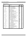
2
1-2
1-2
1-3
1-5
1-5
1-5
1-5
1-5
1-6
1-6
Getting Started ....................................................................................... 2-1
Introduction ................................................................................................. 2-2
Front and rear panel familiarization ............................................................ 2-2
Front panel summary ........................................................................... 2-2
Rear panel summary ............................................................................ 2-4
Power-up .................................................................................................... 2-6
Line power connection ......................................................................... 2-6
Line fuse replacement .......................................................................... 2-6
Power-up sequence ............................................................................. 2-7
Display ........................................................................................................ 2-8
Exponent mode (Engineering or Scientific) .......................................... 2-8
Information messages .......................................................................... 2-9
Range messages ................................................................................. 2-9
Status and error messages ................................................................ 2-11
Multiple displays ................................................................................. 2-15
Navigating menus ..................................................................................... 2-17
Menu types......................................................................................... 2-17
Navigation rules ................................................................................. 2-17
Menu......................................................................................................... 2-18
SAVESETUP ...................................................................................... 2-19
TEST .................................................................................................. 2-26
LIMITS................................................................................................ 2-26
STATUS-MSG .................................................................................... 2-26
GENERAL .......................................................................................... 2-26
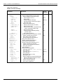
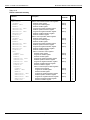
3
Connections ............................................................................................ 3-1
Introduction .................................................................................................
Electrometer input connector......................................................................
Input configurations ..............................................................................
Maximum input levels...........................................................................
Input protection ....................................................................................
Connection methods...................................................................................
High-resistance meter connections ......................................................
Voltage source output connections ......................................................
V-source probes and cables.................................................................
Low noise cables, shielding, and guarding .................................................
Low noise input cables.........................................................................
Shielding and guarding ........................................................................
Floating circuits...........................................................................................
3-2
3-2
3-2
3-3
3-4
3-4
3-4
3-5
3-6
3-6
3-6
3-7
3-9
Table of Contents
Model 6517B Electrometer Reference Manual
Floating measurements ........................................................................ 3-9
Floating voltage source....................................................................... 3-10
Test fixtures ............................................................................................... 3-11
Keithley Instruments Model 8009 test fixture...................................... 3-11
Custom built test fixtures .................................................................... 3-11
4
Basic Measurements ............................................................................. 4-1
Introduction ................................................................................................. 4-2
Voltage measurements ............................................................................... 4-2
Basic measurement procedure............................................................. 4-2
Volts configuration ................................................................................ 4-5
Voltage measurement considerations................................................... 4-6
Current measurements ............................................................................... 4-9
Basic measurement procedure............................................................. 4-9
Amps configuration ............................................................................. 4-11
Current measurement considerations................................................. 4-13
Resistance and resistivity measurements ................................................. 4-18
Overview............................................................................................. 4-18
Resistance measurements ................................................................. 4-19
Resistivity measurements................................................................... 4-22
Ohms configuration ............................................................................ 4-27
Ohms measurement considerations ................................................... 4-30
Charge measurements (Q) ....................................................................... 4-31
Basic measurement procedure........................................................... 4-31
Coulombs configuration ...................................................................... 4-33
Charge measurement considerations................................................. 4-34
Other measurement considerations .......................................................... 4-35
Ground loops ...................................................................................... 4-35
Triboelectric effects............................................................................. 4-36
Piezoelectric and stored charge effects.............................................. 4-36
Electrochemical effects....................................................................... 4-36
Humidity.............................................................................................. 4-36
Light .................................................................................................... 4-37
Electrostatic interference .................................................................... 4-37
Magnetic fields.................................................................................... 4-37
Electromagnetic interference (EMI) .................................................... 4-38
Relative humidity and external temperature readings ........................ 4-38
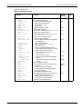
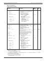
5
ii
Measurement Options ........................................................................... 5-1
Introduction ................................................................................................. 5-2
Voltage source ............................................................................................ 5-2
V-Source configuration ......................................................................... 5-2
Sourcing options ................................................................................... 5-3
Setting voltage source value................................................................. 5-6
Voltage and current limit ....................................................................... 5-7
Interlock and test fixtures...................................................................... 5-7
Operate................................................................................................. 5-8
Analog outputs ............................................................................................ 5-8
2 V analog output ................................................................................. 5-9
Preamp out ......................................................................................... 5-11
Using external feedback............................................................................ 5-12
Electrometer input circuitry ................................................................. 5-12
Shielded fixture construction .............................................................. 5-13
External feedback procedure.............................................................. 5-14
Non-standard coulombs ranges.......................................................... 5-15
Logarithmic currents ........................................................................... 5-15
Non-decade current gains .................................................................. 5-16
Range and resolution ................................................................................ 5-17
Measurement range ........................................................................... 5-17
Display resolution ............................................................................... 5-17
Zero check, relative, and zero correct....................................................... 5-18
Zero check .......................................................................................... 5-18
Relative (REL) .................................................................................... 5-19
Zero correct ........................................................................................ 5-20
6517B-901-01 Rev. B / June 2009
Model 6517B Electrometer Reference Manual
6
Table of Contents
Test Sequences ...................................................................................... 6-1
Introduction ................................................................................................. 6-2
Test sequences ........................................................................................... 6-2
Test descriptions ......................................................................................... 6-2
Diode leakage current test.................................................................... 6-2
Capacitor leakage current test.............................................................. 6-4
Cable insulation resistance test ............................................................ 6-4
Resistor voltage coefficient test ............................................................ 6-5
Standard method resistivity tests .......................................................... 6-6
Alternating polarity resistance/resistivity test ........................................ 6-7
Surface insulation resistance (SIR) test................................................ 6-8
Sweep tests (square wave and staircase) ............................................ 6-9
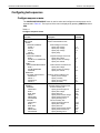
Configuring test sequences....................................................................... 6-11
Configure sequence menu.................................................................. 6-11
Menu sections..................................................................................... 6-12
Running the selected test ................................................................... 6-14
7
Triggering ................................................................................................. 7-1
Introduction ................................................................................................. 7-2
Trigger configuration menu ......................................................................... 7-2
Trigger models ............................................................................................ 7-4
Basic trigger model ............................................................................... 7-4
Advanced trigger model........................................................................ 7-5
Trigger model layers ............................................................................. 7-7
Trigger configuration ................................................................................... 7-8
Basic trigger configuration .................................................................... 7-8
Advanced trigger configuration ............................................................. 7-9
External triggering ..................................................................................... 7-14
Trigger link connector ......................................................................... 7-14
Asynchronous operation ..................................................................... 7-14
Semi-synchronous operation .............................................................. 7-18
8
Buffer (Data Store) ................................................................................. 8-1
9
Filters and Math ...................................................................................... 9-1
Introduction .................................................................................................
Buffer overview ...........................................................................................
Maximum readings ...............................................................................
Data elements.......................................................................................
Configuring data storage .............................................................................
Data store configuration menu..............................................................
Storing and recalling readings ..............................................................
Buffer multiple displays.........................................................................
8-2
8-2
8-2
8-2
8-3
8-4
8-6
8-7
Introduction ................................................................................................. 9-2
Filters .......................................................................................................... 9-2
Digital filters .......................................................................................... 9-2
Median filter .......................................................................................... 9-3
Configuring the filters............................................................................ 9-5
Math ............................................................................................................ 9-7
Polynomial ............................................................................................ 9-7
Percent ................................................................................................. 9-7
Percent deviation .................................................................................. 9-8
Deviation............................................................................................... 9-8
Ratio ..................................................................................................... 9-8
Logarithmic ........................................................................................... 9-8
Selecting and configuring math ............................................................ 9-9
Math multiple display .......................................................................... 9-10
10
Limits, Digital I/O, and Scanning ...................................................... 10-1
Introduction ...............................................................................................
Limits .........................................................................................................
Setting limits .......................................................................................
Strobe control .....................................................................................
Pass pattern........................................................................................
6517B-901-01 Rev. B / June 2009
10-2
10-2
10-2
10-4
10-4
iii
Table of Contents
Model 6517B Electrometer Reference Manual
Limits example....................................................................................
Digital I/O ..................................................................................................
Digital I/O menu ..................................................................................
Digital I/O port.....................................................................................
Scanning ...................................................................................................
Internal scanning ................................................................................
External scanning ...............................................................................
11
10-4
10-5
10-5
10-6
10-9
10-9
10-9
Remote Operations .............................................................................. 11-1
Introduction ............................................................................................... 11-2
Standards............................................................................................ 11-2
RS-232 serial port............................................................................... 11-2
Connections .............................................................................................. 11-2
IEEE-488 bus connections ................................................................. 11-2
RS-232 interface connections ............................................................ 11-4
Selecting interface parameters ................................................................. 11-4
Communication menu......................................................................... 11-4
GPIB primary address selection ......................................................... 11-5
General bus commands ............................................................................ 11-6
REN (remote enable).......................................................................... 11-6
IFC (interface clear) ............................................................................ 11-6
LLO (local lockout).............................................................................. 11-7
GTL (go to local) ................................................................................. 11-7
DCL (device clear) .............................................................................. 11-7
SDC (selective device clear)............................................................... 11-7
GET (group execute trigger) ............................................................... 11-7
SPE, SPD (serial polling).................................................................... 11-7
IEEE-488 front panel operation................................................................. 11-7
Error and status messages................................................................. 11-8
IEEE-488 status indicators ................................................................. 11-8
LOCAL key ......................................................................................... 11-8
Programming syntax ................................................................................. 11-8
Command words ................................................................................ 11-8
Program messages .......................................................................... 11-11
Response messages ........................................................................ 11-13
Message exchange protocol............................................................. 11-13
IEEE-488 trigger model........................................................................... 11-14
Idle and initiate ................................................................................. 11-14
Trigger model layers ......................................................................... 11-14
RS-232 serial interface............................................................................ 11-17
RS-232 Interface configuration ......................................................... 11-17
RS-232 operating considerations ..................................................... 11-18
Error messages ................................................................................ 11-19
12
Common Commands .......................................................................... 12-1
Introduction ............................................................................................... 12-2
Common command summary ................................................................... 12-2
Common command descriptions............................................................... 12-2
13
Status Structure .................................................................................... 13-1
Introduction ............................................................................................... 13-2
Status register sets.................................................................................... 13-2
Condition registers.............................................................................. 13-9
Transition filters .................................................................................. 13-9
Event registers.................................................................................. 13-10
Enable registers................................................................................ 13-10
Queues.................................................................................................... 13-11
Output queue .................................................................................... 13-11
Error queue ..................................................................................... 13-11
Status byte and service request (SRQ)................................................... 13-11
Status byte register ........................................................................ 13-11
Service request enable register .................................................... 13-13
Serial poll and SRQ .......................................................................... 13-13
iv
6517B-901-01 Rev. B / June 2009
Model 6517B Electrometer Reference Manual
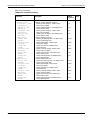
14
Table of Contents
SCPI Command Reference ................................................................ 14-1
Introduction ............................................................................................... 14-2
Signal-oriented measurement commands ................................................ 14-2
SCPI command summary ......................................................................... 14-4
SCPI command subsystems ................................................................... 14-25
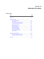
15
Calibration Procedure ......................................................................... 15-1
Introduction ............................................................................................... 15-2
Calibration procedure................................................................................ 15-2
Environmental conditions.................................................................... 15-2
Warm-up period .................................................................................. 15-2
Recommended calibration equipment ................................................ 15-2
Comprehensive calibration procedure ................................................ 15-2
Restoring factory defaults ................................................................... 15-3
Unlocking calibration........................................................................... 15-3
Voltage offset calibration..................................................................... 15-3
Current offset calibration..................................................................... 15-5
Current ranges calibration .................................................................. 15-6
Coulombs ranges calibration .............................................................. 15-8
Voltage measurement ranges calibration ........................................... 15-9
Voltage source calibration................................................................. 15-10
Humidity calibration .......................................................................... 15-11
Temperature calibration .................................................................... 15-11
Set calibration dates ......................................................................... 15-11
Save calibration ................................................................................ 15-11
Lock calibration................................................................................. 15-12
Partial calibration .............................................................................. 15-12
Calibration command reference .............................................................. 15-14
Voltage offset calibration commands ................................................ 15-14
Current offset calibration commands ................................................ 15-14
Charge calibration commands .......................................................... 15-15
Current calibration commands.......................................................... 15-16
Voltage measurement calibration commands................................... 15-17
Voltage source calibration commands .............................................. 15-18
Humidity calibration commands........................................................ 15-18
Temperature calibration commands.................................................. 15-19
Error codes.............................................................................................. 15-20
16
Verification Procedure ........................................................................ 16-1
Introduction ............................................................................................... 16-2
Equipment needed for verification ...................................................... 16-2
Warm up time and environment.......................................................... 16-3
Considerations.................................................................................... 16-3
Verification Procedures ............................................................................. 16-3
DC voltage verification........................................................................ 16-4
DC amps verification........................................................................... 16-5
Coulombs verification ......................................................................... 16-7
Voltage source verification.................................................................. 16-8
Temperature verification ..................................................................... 16-9
Humidity verification.......................................................................... 16-10
................................................................................................................ 16-12
A
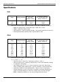
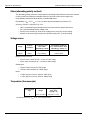
Specifications ........................................................................................ A-1
Specifications .............................................................................................
Volts .....................................................................................................
Amps....................................................................................................
Coulombs.............................................................................................
Ohms (normal method)........................................................................
Ohms (alternating polarity method) .....................................................
Voltage source .....................................................................................
Temperature (thermocouple) ...............................................................
Humidity...............................................................................................
General ................................................................................................
6517B-901-01 Rev. B / June 2009
A-2
A-2
A-2
A-3
A-3
A-4
A-4
A-4
A-5
A-5
v
Table of Contents
B
Model 6517B Electrometer Reference Manual
Accuracy Calculations ......................................................................... B-1
Introduction ................................................................................................
Calculating volts accuracy ...................................................................
Calculating amps accuracy..................................................................
Calculating ohms accuracy..................................................................
Calculating coulombs accuracy ...........................................................
Calculating resistance/resistivity accuracy ..........................................
C
B-2
B-2
B-2
B-2
B-3
B-3
Interface Function Codes .................................................................... C-1
Interface function codes ............................................................................. C-2
Code summary .................................................................................... C-2
Code descriptions ................................................................................ C-2
D
ASCII Character Codes ........................................................................ D-1
Introduction ................................................................................................ D-2
Code summary........................................................................................... D-2
E
IEEE-488 Bus Overview ....................................................................... E-1
Introduction ................................................................................................ E-2
Bus description........................................................................................... E-2
Bus lines..................................................................................................... E-4
Data lines............................................................................................. E-4
Bus management lines ........................................................................ E-4
Handshake lines .................................................................................. E-4
Bus commands .......................................................................................... E-5
Uniline commands ............................................................................... E-6
Universal multiline commands ............................................................. E-6
Addressed multiline commands........................................................... E-7
Addressed commands ......................................................................... E-7
Unaddress commands......................................................................... E-7
Common commands ........................................................................... E-7
SCPI commands.................................................................................. E-8
Command codes ................................................................................. E-8
Typical command sequences .............................................................. E-9
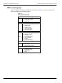
IEEE command groups...................................................................... E-10
F
IEEE-488 Conformance ......................................................................... F-1
Information .................................................................................................. F-2
G
SCPI Conformance ............................................................................... G-1
Introduction ................................................................................................ G-2
Index ............................................................................................................................ I-1
vi
6517B-901-01 Rev. B / June 2009
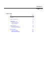
Section 1
Introduction
In this section:
Topic
Page
Introduction
Capabilities and features overview
Available options and accessories
Manual addenda
Specifications
Warranty information
1-2
1-2
1-3
1-5
1-5
1-5
Unpacking and inspection
Inspection for damage
Shipment contents
Repacking for shipment
1-5
1-5
1-6
1-6
Section 1: Introduction
Model 6517B Electrometer Reference Manual
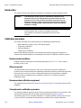
Introduction
This Reference Manual is provided on the supplied product information CD in PDF format. The
User’s Manual, also provided on the supplied product information CD in PDF format, is an
abbreviated version of the operation sections of this Reference Manual.
This section contains general information about the Keithley Instruments Model 6517B
Electrometer.
If you have any questions after reviewing this information, please contact your local Keithley
Instruments representative or call one of our applications engineers at 1-888-KEITHLEY
(1-888-534-8453) within the U.S. and Canada. You can also visit the Keithley Instruments website
to contact the applications engineering department online, at www.keithley.com, or for updated
worldwide contact information.
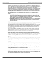
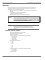
Capabilities and features overview
The Model 6517B is a 6½-digit Electrometer/high-resistance system with the following
measurement capabilities:
•
•
•
•
•
•
•
•
DC voltage measurements from 1 µV to 210 V
DC current measurements from 10 aA to 21 mA
Charge measurements from 10 fC to 2.1 µC
Resistance measurements from 10 Ω to 210 PΩ
Surface resistivity measurements
Volume resistivity measurements
External temperature measurements from –25° C to 150° C using the supplied
Model 6517-TP thermocouple
Relative humidity measurements (0 to 100%) using the optional Model 6517-RH probe
Some additional capabilities of the Model 6517B include:
•
•
•
•
•
•
•
•
•
1-2
Built-in V-Source: The 100 V range provides up to ± 100V at 10 mA, while the 1000 V range
provides up to ±1000 V at 1 mA.
Data storage (50,000 points)
Single button zeroing (REL)
Built-in math functions
Filtering: averaging and median
Built-in test sequences
Remote operation using the IEEE-488 (GPIB) bus or the RS-232 interface
Scan (measure) channels of an external scanner
Scan (measure) channels of an internal scanner card (for example, Model 6521 or
Model 6522) installed in the option slot
Return to Section Topics
6517B-901-01 Rev. B / June 2009
Model 6517B Electrometer Reference Manual
Section 1: Introduction
Available options and accessories
NOTE
Check the Keithley Instruments website (www.keithley.com) for additional options and
accessories that may have been added to the Keithley Instruments product line for use
with the Model 6517B Electrometer.
The following options and accessories are available from Keithley Instruments for use with the
Model 6517B Electrometer:
Cables and adapters
Model 237-ALG-2 Triax Cable: This is a 2 m (6.6 ft) low noise triax cable terminated with a 3-slot
male triax connector on one end and three alligator clips on the other.
Model 237-BNC-TRX Adapter: This is a male BNC to 3-lug female triax adapter (guard
disconnected). It is used to terminate a triax cable with a BNC plug. Suitable for use with the
Model 6517B V-Source in high voltage applications.
Model 237-TRX-T Adapter: This is a 3-slot male to dual 3-lug female triax tee adapter for use with
Model 7078-TRX triax cables. Suitable for use with the Mode 6517B V-source in high voltage
applications.
Model 237-TRX-TBC Connector: This is a 3-lug female triax bulkhead connector with cap for
assembly of custom panels and interface connections. Suitable for use with the Model 6517B
V-source in high voltage applications.
Model 6517B-ILC-3 Interlock Cable: This is a 3 m (9.8 ft) cable terminated with a 4-pin Phoenix
Connector on one end and a 4-pin Switchcraft connector on the other end.
Model 7078-TRX-BNC Adapter: This is a 3-slot male triax to female BNC adapter. This adapter
lets you connect a BNC cable to the triax input of the Model 6517B. Suitable for use with the
Model 6517B in high voltage applications.
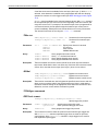
Models 7078-TRX-3, 7078-TRX-10 and 7078-TRX-20 Triax Cables: These are low noise triax
cables terminated at both ends with 3-slot male triax connectors.
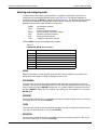
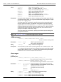
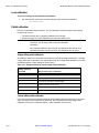
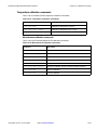
Table 1-1
Triax cable lengths
Model
Metric length
Imperial length
Model 7078-TRX-3
Model 7078-TRX-10
Model 7078-TRX-20
0.9 m
3m
6m
3 ft
10 ft
20 ft
Model 7078-TRX-TBC Connector: This is a 3-lug female triax bulkhead connector with cap for
assembly of custom panels and interface connections. Suitable for use with the Model 6517B
V-source in high voltage applications.
Models 7007-1 and 7007-2 Shielded IEEE-488 Cables: Connect the Model 6517B to the
IEEE-488 bus using shielded cables and connectors to reduce electromagnetic interference (EMI).
The Model 7007-1 is 1 m in length; the Model 7007-2 has a length of 2 m.
Models 8501-1 and 8501-2 Trigger Link Cables: Connect the Model 6517B to other instruments
with trigger link connectors (for example, Model 7001 Switch System). The Model 8501-1 is 1 m
long; the Model 8501-2 is 2 m long.
Model 8502 Trigger Link Adapter: Allows you to connect the trigger link of the Model 6517B to
instruments that use the standard BNC (in/out) external triggering technique.
6517B-901-01 Rev. B / June 2009
Return to Section Topics
1-3
Section 1: Introduction
Model 6517B Electrometer Reference Manual
Model 8606 High Performance Probe Tip Kit: Consists of two spade lugs, two alligator clips, and
two spring hook test probes. (The spade lugs and alligator clips are rated at 30 V RMS,
42.4 V peak; the test probes are rated at 1000 V.) These components are designed to be used
with high performance test leads terminated with banana plugs, such as the Model 8607 High
Performance Banana Cables.
Model 8607 High Performance Banana Cables: Consists of two high voltage (1000 V) banana
cables. The cables are terminated with banana plugs that have retractable sheaths.
CS-751 Barrel Adapter: This is a barrel adapter that allows you to connect two triax cables
together. Both ends of the adapter are terminated with 3-lug female triax connectors.
Case and rack mount kits
Model 1050 Padded Carrying Case: A carrying case for a Model 6517B. Includes handles and
shoulder strap.
Model 4299-1 Single Fixed Rack Mount Kit: Mounts a single Model 6517B in a standard 19 inch
rack.
Model 4299-2 Side-by-side Rack Mount Kit: Mounts two instruments side by side in a standard
19 inch rack.
Model 4288-4 Side-by-side Rack Mount Kit: Mounts a Model 6517B and a 51/4 inch instrument
side-by-side in a standard 19 inch rack.
Probes
Model 6517-RH Humidity Probe with Cable: This sensor allows the Model 6517B to make
relative humidity measurements (0% to 100%). Also included is an extension cable (part number
CA-129-1).
Model 6517-TP Thermocouple with Leads: This type K thermocouple sensor allows the Model
6517B to make external temperature measurements from –190° C to 1350° C.
Scanner cards
Model 6521 Low Current Scanner Card: This 10-channel low current scanner card is terminated
with BNC connectors and plugs into the option slot of the Model 6517B.
Model 6522 Low Current/Low Voltage Scanner Card: This 10-channel low current/low voltage
scanner card is terminated with triax connectors and plugs into the option slot of the Model 6517B.
Test fixture
Model 8009 Resistivity test Fixture: This is a guarded test fixture for measuring volume and
surface resistivities. It can accommodate sheet samples 64 mm to 102 mm (2½ to 4 inches) in
diameter and up to 3.175 mm (1/8 inches) thick.
1-4
Return to Section Topics
6517B-901-01 Rev. B / June 2009
Model 6517B Electrometer Reference Manual
Section 1: Introduction
Software
Model 6524 Hi-R Software Package: Designed to aid in making more repeatable high resistance/
resistivity measurements. Four windows-driven programs increase measurement precision, ease
download and analysis of Hi-R data, and allow cross-correlation of environmental factors.
Manual addenda
Any improvements or changes concerning the Model 6517B or manuals will be explained in an
addendum included with the manual. Be sure to note these changes and incorporate them into the
manual.
Specifications
Full Model 6517B specifications are included in Appendix B. Check the Keithley Instruments
website at www.keithley.com for the latest updates to the specifications.
Warranty information
Warranty information is located at the front of this manual. Should your Model 6517B Electrometer
require warranty service, contact the Keithley Instruments representative or authorized repair
facility in your area for further information. When returning the instrument for repair, be sure to fill
out and include the service form at the back of this manual to provide the repair facility with the
necessary information.
Unpacking and inspection
Inspection for damage
The Model 6517B was carefully inspected electrically and mechanically before shipment. After
unpacking all items from the shipping carton, check for any obvious signs of physical damage that
may have occurred during transit. There may be a protective film over the display lens, which can
be removed. Report any damage to the shipping agent immediately. Save the original packing
carton for possible future shipment. Before removing the Model 6517B from the anti-static bag,
observe the following handling precautions.
Handling precautions
•
•
•
6517B-901-01 Rev. B / June 2009
Always grasp the Model 6517B by the covers.
After removing the Model 6517B from its anti-static bag, inspect it for any obvious signs
of physical damage. Report any such damage to the shipping agent immediately.
When the Model 6517B is not installed and connected, keep the unit in its anti-static
bag and store it in the original packing carton.
Return to Section Topics
1-5
Section 1: Introduction
Model 6517B Electrometer Reference Manual
Shipment contents
The following items are included with every Model 6517B order:
•
•
•
•
•
Model 6517B Electrometer with line cord
Protective Triax Shield/Cap (CAP-28-1)
237-ALG-2 Triax Cable terminated with alligator clips on one end
Accessories as ordered
Certificate of calibration
Always check the Keithley Instruments website at www.keithley.com for the latest revision of the
instruction manuals, which can be downloaded (in PDF format) from the website.
Repacking for shipment
Should it become necessary to return the Model 6517B for repair, carefully pack the unit in the
original packing carton or the equivalent, and follow these instructions:
•
•
•
1-6
Call the repair department toll-free at 1-888-KEITHLEY (1-888-534-8453), within the U.S.
and Canada, to obtain a Return Material Authorization (RMA) number.
Advise as to the warranty status of the Model 6517B.
Write ATTENTION REPAIR DEPARTMENT and the RMA number on the shipping label.
Return to Section Topics
6517B-901-01 Rev. B / June 2009
Section 2
Getting Started
In this section:
Topic
Page
Introduction .............................................................................................
2-2
Front and rear panel familiarization.........................................................
Front panel summary ......................................................................
Rear panel summary.......................................................................
2-2
2-2
2-4
Power-up.................................................................................................
Line power connection ....................................................................
Line fuse replacement.....................................................................
Power-up sequence ........................................................................
2-6
2-6
2-6
2-7
Display ....................................................................................................
Exponent mode (Engineering or Scientific).....................................
Information messages.....................................................................
Range messages ............................................................................
Status and error messages .............................................................
Multiple displays..............................................................................
2-8
2-8
2-9
2-9
2-11
2-15
Navigating menus ...................................................................................
Menu types .....................................................................................
Navigation rules ..............................................................................
2-17
2-17
2-17
Menu .......................................................................................................
SAVESETUP...................................................................................
TEST ...............................................................................................
LIMITS ............................................................................................
STATUS-MSG .................................................................................
GENERAL .......................................................................................
2-18
2-19
2-26
2-26
2-26
2-26
Section 2: Getting Started
Model 6517B Electrometer Reference Manual
Introduction
This section contains identification and descriptions of controls and components of the Keithley
Instruments Model 6517B Electrometer and detailed information for powering up the Model 6517B.
Front and rear panel familiarization
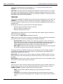
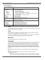
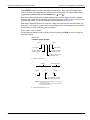
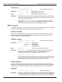
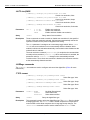
Front panel summary
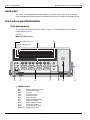
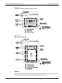
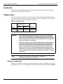
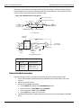
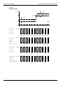
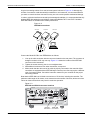
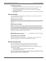
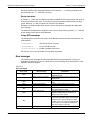
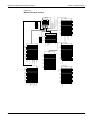
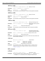
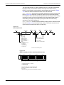
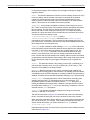
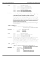
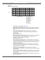
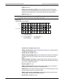
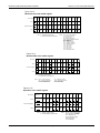
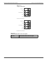
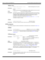
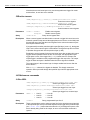
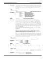
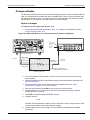
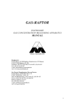
The front panel of the Model 6517B is shown in Figure 2-1. The descriptions of the front panel
controls follow Figure 2-1.
Figure 2-1
Model 6517B front panel
1
Secondary display line
9
Primary display line
EDIT ERR REM TALK
1
2
3
4
5
LSTN SRQ REAR
6
7
8
9
REL FILT MATH
10
1
2
3
4W AUTO
4
5
6
ARM TRIG
7
8
9
SMPL
10
VOLTAGE
SOURCE
OPERATE
6517B ELECTROMETER/HIGH RESISTANCE METER
OPTION
V
PREV
DISPLAY
NEXT
I
R
Z-CHK REL
Q
CARD
VOLTAGE SOURCE
OPER
RANGE
FILTER MATH
TRIG
AUTO
SEQ
RANGE
POWER
INFO LOCAL
5
STORE RECALL
2
CONFIG MENU
EXIT ENTER
6
7
3
8
4
1 ANNUNCIATORS
EDIT
ERR
REM
TALK
LSTN
SRQ
REL
FILT
MATH
AUTO
ARM
*(asterisk)
2-2
Editing voltage source values
Questionable reading
In remote
Addressed to talk
Addressed to listen
Service Request
Relative reading displayed
Digital filter enabled
Math calculation enabled
Autoranging enabled
Trigger armed; not in idle
Reading being stored
Return to Section Topics
6517B-901-01 Rev. B / June 2009
Model 6517B Electrometer Reference Manual
Section 2: Getting Started
2 FUNCTION KEYS
Select measurement function; volts (V), amps (I), resistivity (R) or coulombs (Q).
3 RANGE KEYS
AUTO
Moves to higher range; increments digit.
Moves to lower range; decrements digit.
Enables/disables autorange.
4 HANDLE
Pull out and rotate to desired position.
5 DISPLAY KEYS
PREV/NEXT Scroll through multiple displays of a function.
6 OPERATION KEYS
Z-CHK
REL
FILTER
MATH
TRIG
SEQ
and
INFO
LOCAL
STORE
RECALL
CONFIG
MENU
EXIT
ENTER
Enables/disables zero check; enable zero check before changing functions.
Enables/disables relative reading.
Displays digital filter status for present function and toggles filter on/off.
Displays math calculation and toggles math on/off if configured.
Triggers unit.
Performs selected test sequence.
Moves cursor among data entry digits, menu selections, and information displays.
Shows context-sensitive information about the present display.
Cancels remote operation.
Enables data storage.
Displays reading data (reading, number, time);
use PREV/NEXT DISPLAY for maximum, minimum average, standard deviation.
Configures functions and operations.
Saves/restores instrument conditions; sets up communications; performs calibration
and self-tests; defines limits, digital output, and other miscellaneous operations.
Cancels selection, moves back within menu structure.
Holds reading, enters selection, moves down within menu structure.
7 VOLTAGE SOURCE KEYS
OPER
and
Toggles V-source between operate and standby.
Adjusts V-source value.
8 VOLTAGE SOURCE OPERATE
Indicator on when in operate, off when in standby.
9 OPTION CARD KEY
Use to program and operate an installed option. Also used to scan external scanner channels.
6517B-901-01 Rev. B / June 2009
Return to Section Topics
2-3
Section 2: Getting Started
Model 6517B Electrometer Reference Manual
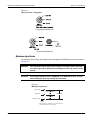
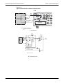
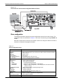
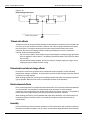
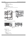
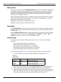
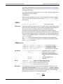
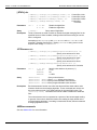
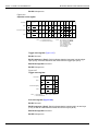
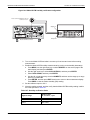
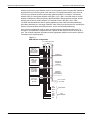
Rear panel summary
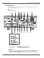
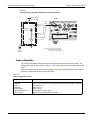
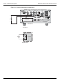
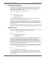
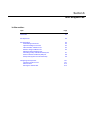
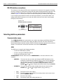
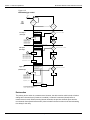
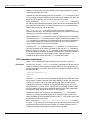
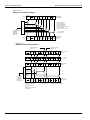
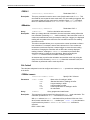
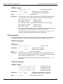
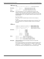
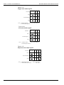
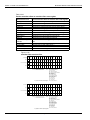
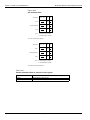
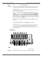
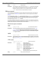
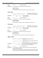
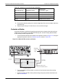
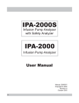
The rear panel of the Model 6517B is shown in Figure 2-2. The descriptions of the rear panel
components follow Figure 2-2.
Figure 2-2
Model 6517B rear panel
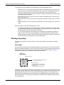
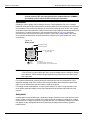
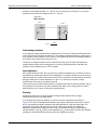
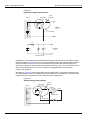
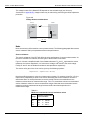
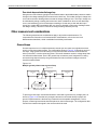
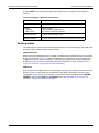
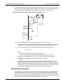
1 INPUT CONNECTOR
Unguarded Configuration
Guarded Configuration
Disable GUARD for amps, ohms, coulombs
and unguarded volts measurements
Enable GUARD for guarded volts measurements
2 PREAMP OUT
Follows the signal amplitude applied to the INPUT terminal. With GUARD on, PREAMP OUT is internally
connected to the inner shell of the INPUT triax connector to configure the input for guarded volts
measurements. Referenced to COMMON. Rated at 200 V DC max. See Section 5 for more information.
2-4
Return to Section Topics
6517B-901-01 Rev. B / June 2009
Model 6517B Electrometer Reference Manual
Section 2: Getting Started
3 COMMON
Connector that is internally connected to INPUT low.
4 CHASSIS GROUND
Attached cable that connects the chassis to ground through the power line cord. COMMON can also be
grounded by plugging the cable into COMMON. For floating measurements, make sure the cable
connection between COMMON and Chassis Ground is open.
5 2V ANALOG OUTPUT
Connector that provides a scaled 0 V to 2 V output that is referenced to COMMON. Typically connected to
a measuring device such as a chart recorder. Rated at 2 V DC max. See Section 5 for more information.
6 HUMIDITY
Connect the optional Model 6517-RH probe for relative humidity measurements.
7 TEMP TYPE K
Connect the Model 6517-TP type K thermocouple for temperature measurements.
8 POWER LINE INPUT MODULE
Provides connections for power line input and contains the line fuse. If the fuse needs to be replaced, refer
to Line fuse replacement.
9 IEEE-488 CONNECTOR
Connects the instrument to the IEEE-488 (GPIB) bus; use shielded IEEE-488 cables.
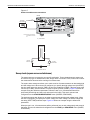
10 INTERLOCK
Connects the safety interlock to a test fixture using an appropriate cable. Interlock is automatically enabled
when the appropriate interlock cable is connected to the Model 6517B. Rated at 50 Hz to 60 Hz, 140 VA
max. The interlock’s CS-1305 connector includes four pins (left to right as viewed from rear of the Model
6517B):
• Pin 1: Interlock safe
• Pin 2: Ground
• Pin 3: +5 VDC output
• Pin 4: Surface/volume select (low = volume, high = surface)
See Section 5 for more information.
11 RS-232
DB-9 connector for the RS-232 interface; use a standard RS-232 cable.
12 DIGITAL I/O
A male DB-9 connector for the four TTL-compatible digital output lines.
13 TRIGGER LINK
An 8-pin micro DIN connector for sending and receiving trigger pulses to and from other instruments.
14 V-SOURCE HI and LO
Safety banana jacks for the voltage source. Rated at 1000 V max.
15 OPTION SLOT
An option card, such as the Model 6521 or Model 6522 scanner card, installs in this slot.
6517B-901-01 Rev. B / June 2009
Return to Section Topics
2-5
Section 2: Getting Started
Model 6517B Electrometer Reference Manual
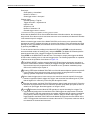
Power-up
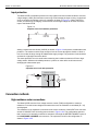
Line power connection
Follow the procedure below to connect the Model 6517B to line power and turn on the instrument
CAUTION
1.
NOTE
2.
Operating the instrument on an incorrect line voltage may cause damage to
the instrument, possibly voiding the warranty.
Before plugging in the power cord, make sure that the front panel power switch is in the off
(O) position. Be sure that line input voltage is set to the correct range for the power supply
being used to power the Model 6517B.
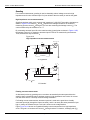
Line voltage is pre-set at the factory, but may be reset in the field by adjusting the voltage
selector behind the left ear (when looking at the front panel of the Model 6517B). To
access the voltage selector, first remove the handle then remove the left mounting ear.
The current voltage setting is the marking closest to the small circle.
Connect the female end of the supplied power cord to the AC receptacle on the rear panel.
Connect the other end of the power cord to a grounded AC outlet.
WARNING
The power cord supplied with the Model 6517B contains a separate ground
wire for use with grounded outlets. When proper connections are made,
instrument chassis is connected to power line ground through the ground
wire in the power cord. Failure to use a grounded outlet may result in personal
injury or death due to electric shock.
Line fuse replacement
A rear panel fuse located in the power module protects the power line input of the instrument. A
rear panel fuse drawer is located below the AC receptacle (see Figure 2-2 item number 8). This
fuse protects the power line input of the instrument. If the line voltage fuse needs to be replaced,
perform the following steps.
WARNING
1.
2.
3.
2-6
Make sure the instrument is disconnected from the AC line and other
equipment before changing the line voltage setting or replacing the line fuse.
On the side of the fuse holder are two small tabs. Use a small flat blade screwdriver to pry
the fuse drawer open.
Slide the fuse drawer out to gain access to the fuses. Snap the old fuse out of the drawer
and replace it with the same type:
a) For 100 V and 120 V line voltage, use a 0.630 A, 250 V, 5 mm x 20 mm fuse
(Keithley P/N: FU-106-.630).
b) For 220 V and 240 V line voltage, use a 0.315 A, 250 V, 5 mm x 20 mm fuse
(Keithley P/N: FU-106-.315).
Push the fuse drawer back into the power module.
Return to Section Topics
6517B-901-01 Rev. B / June 2009
Model 6517B Electrometer Reference Manual
CAUTION
Section 2: Getting Started
For continued protection against fire or instrument damage, only replace fuse
with the type and rating listed. If the instrument repeatedly blows fuses, locate
and correct the cause of the problem before replacing the fuse.
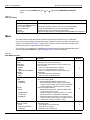
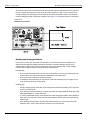
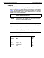
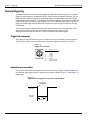
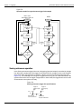
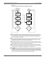
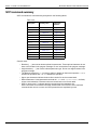
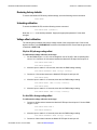
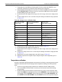
Power-up sequence
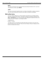
When the Model 6517B is powered up, it performs self-tests on its EPROM and RAM, and
checksum tests on data stored in non-volatile memory (see Table 2-1). If a failure is detected, the
instrument momentarily displays an error message and the ERR annunciator turns on (messages
are listed in Table 2-2). If a problem develops while the instrument is under warranty, return it to
Keithley Instruments for repair.
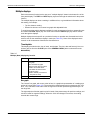
If the instrument passes the self-tests, the firmware revision levels and the communications status
are displayed. An example of this display is shown as follows:
Model 6517B
Rev. A01 700x SCPI: 27
The firmware revision levels (left to right) are for the main microcontroller and display
microcontroller. The revision level number may be different in your particular unit. The IEEE-488
address is its default value of 27 and the SCPI language is selected. If the RS-232 interface is
selected, the message “RS-232 MODE” is displayed instead of the IEEE-488 address.
Next, if the unit is configured to display the calibration due date when it is turned on, the unit shows
the following:
Model 6517B
Calibration due: mmm/dd/yy
Where: “mmm” is the month abbreviation, “dd” is the day, and “yy” is the year. If no calibration date
is set, the display shows that it is due now.
After the power-up sequence, the instrument begins its normal display with zero check enabled
(“Zero Check” displayed).
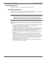
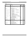
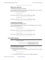
Power-up error messages
Error messages that may be displayed during the power-up sequence are summarized in
Table 2-2. These are shown when one of the checksum tests listed in Table 2-1 fails.
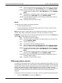
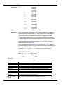
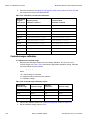
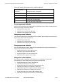
Table 2-1
Data checked on power-up
Data
Type of storage
IEEE-488 address
Power-up default
Calibration constants
Calibration dates
Instrument setups
Reading buffer
Electrically-erasable PROM
Electrically-erasable PROM
Electrically-erasable PROM
Electrically-erasable PROM
10 in electrically-erasable PROM
Non-volatile RAM
6517B-901-01 Rev. B / June 2009
Return to Section Topics
2-7
Section 2: Getting Started
Model 6517B Electrometer Reference Manual
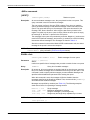
Table 2-2
Power-up error messages
Message
Description
Action
Error -314,
Save/recall memory lost
Error +510
Reading buffer data lost
Error +511
GPIB address lost
Error +512
Power-up state lost
Error +514
Calibration lost
Error +515
Calibration dates lost
Instrument setup is reset to bench defaults are
stored in EEPROM.
The reading buffer controls are reset to factory
defaults, but they are not stored into NVRAM. To
do this, store readings in the buffer.
GPIB address is reset to factory default (27) and
stored into EEPROM.
Power-up defaults are reset to factory defaults
(bench) and stored into EEPROM.
Cal constants are set to factory default values, but
they are not stored into EEPROM. To do this,
perform a comprehensive calibration.
The cal dates are set to factory default values, but
they are not stored into EEPROM. To do this,
perform a comprehensive calibration.
Note: Any of these error conditions may occur the first time a unit is turned on or after replacing the firmware.
Power-up default conditions
Power-up default conditions are those conditions the instrument assumes when it is first turned on.
You can change these power-up default conditions (except the primary address) by using the save
setup feature that is available with the MENU key.
Warmup period
The Model 6517B can be used within one minute after it is turned on. However, the instrument
should be turned on and allowed to warm up for at least one hour before use to achieve rated
accuracy.
IEEE-488 primary address
The IEEE-488 primary address of the instrument must be the same as the primary address you
specify in the controller's programming language. The default primary address of the instrument is
27, but you can set the address to any value from 0 to 30 by using the MENU key.
Display
The display of the Model 6517B is primarily used to display readings along with the units and type
of measurement. When not displaying readings, it is used for informational messages, such as
menu headings and selections. At the top of the display are annunciators to indicate various states
of operation.
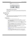
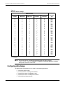
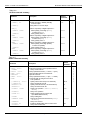
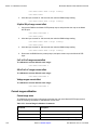
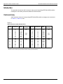
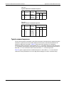
Exponent mode (Engineering or Scientific)
Readings on the display can be expressed in engineering units or in scientific notation as shown in
Table 2-3. In the scientific mode, the exponent can be fixed to a specified value, or it can be
floating. In the floating mode, the instrument will automatically select the exponent value.
2-8
Return to Section Topics
6517B-901-01 Rev. B / June 2009
Model 6517B Electrometer Reference Manual
Section 2: Getting Started
All exponent mode selections are performed from the DISPLAY option of the GENERAL menu,
which is part of the MAIN MENU.
Table 2-3
Typical display exponent values
Engineering units
Scientific notation
Value
Display
Value
Display
Picoamperes
Nanoamperes
pA
10-12 A
10-9 A
e-12A
Microamperes
Milliamps
Nanocoulombs
Microcoulombs
Kilo-ohms
Mega-ohms
Giga-ohms
Tera-ohms
Peta-ohms
nA
µA
mA
nC
µC
kΩ
MΩ
GΩ
TΩ
PΩ
10-6 A
10-3 A
10-9 C
10-6 C
103 Ω
106 Ω
109 Ω
1012 Ω
1015 Ω
e-9A
e-6A
e-3A
e-9C
e-6C
e3Ω
e6Ω
e9Ω
e12Ω
e15Ω
Information messages
Press the INFO key to view context-sensitive information from most of the displays. An arrow
( or ) on the bottom line indicates that there is more information. Use the cursor keys ( and
to view the complete line. To exit an INFO display, just press INFO, ENTER, EXIT or a function
key.
)
Range messages
The following display messages may occur when making measurements:
OVERFLOW: This message is displayed when the integrated (average) input signal level (voltage,
current, or charge) exceeds 105% of full scale for the selected measurement range. For example,
on the 20 nA measurement range, the OVERFLOW message occurs when the integrated input
level exceeds 21 nA.
An OVERFLOW condition can be resolved by selecting a higher measurement range, using AUTO
range, or reducing the magnitude of the input signal.
The OVERFLOW message will NOT occur during resistance or resistivity measurements.
UNDERFLOW: This condition is similar to OVERFLOW but pertains to resistance and resistivity
measurements. An ohms measurement is performed by sourcing voltage and measuring current.
An ohms measurement that is too low causes the current to exceed full scale. The message
UNDERFLOW is used to indicate that the measured resistance or resistivity is lower than the
lower limit of the selected range.
The UNDERFLOW condition can usually be resolved by selecting a lower ohms range or by using
AUTO range.
OUT OF LIMITS: This message indicates that a momentary or transient out-of-range condition
appeared at the input, even though the integrated (or average) signal was within the full scale
range of the analog to digital converter (A/D). It usually indicates that there is too much noise on
the input signal for a valid measurement or that the signal exceeds 120% of the range.
6517B-901-01 Rev. B / June 2009
Return to Section Topics
2-9
Section 2: Getting Started
Model 6517B Electrometer Reference Manual
Generally, the OUT OF LIMITS condition can be eliminated by better shielding of the signal source
or by using other noise reduction methods. Another solution is to select the next higher range (or
lower R range) to keep the transients less than full scale.
The 2 nA, 20 nA, 200 nA ranges, and the resistance (R) measurements that use these current
ranges are particularly susceptible to this condition because of the combination of speed and
sensitivity.
A sine wave signal riding on a DC bias level is used to demonstrate an OUT OF LIMIT reading.
Figure 2-3 shows a sine wave riding on a 20 nA bias level. If this signal is measured on the 200 nA
range at normal speed, it would simply read 20 nA (which is the DC average). If however, you use
the 20nA range, the positive peaks of the sine wave will be clipped as shown in Figure 2-4.
Clipping occurs at 110% of full range (22 nA on the 20nA range). Because of clipping, the
measurement of the input signal is significantly less than 20 nA.
To avoid these bad readings, the Model 6517B displays the OUT OF LIMITS message instead of
the inaccurate reading.
Note that the positive peaks of the input signal (which exceed full scale) will not cause an
OVERFLOW condition on the 20 nA range since the average reading over the 16.67 ms
integration period is less than full scale.
The A/D hardware limit detection circuit can be disabled, which in turn disables the OUT OF
LIMITS message. However, the presence of OUT OF LIMIT readings may result in measurements
that are slightly, moderately, or completely inaccurate. When both OVERFLOW and OUT OF
LIMITS conditions occur, the OUT OF LIMIT message will be displayed.
Figure 2-3
Input signal
30
25
nA
20
15
10
DCA Reading on 200 nA range = 20nA
5
0
0
2-10
time
Return to Section Topics
16.67ms
6517B-901-01 Rev. B / June 2009
Model 6517B Electrometer Reference Manual
Section 2: Getting Started
Figure 2-4
Measurement on 20nA range
30
25
nA
22
20
15
10
DCA Reading = <20nA
5
0
0
time
16.67ms
Status and error messages
During Model 6517B operation and programming, you will encounter a number of front panel
messages. Typical messages are either of status or error variety, as listed in Table 2-4.
The most recent status or error messages can be momentarily displayed by entering a
configuration menu or the main menu, and pressing the PREV display key (the display is blank if
no message is queued).
Table 2-4
Status and error messages
Number
Description
Event
-440
-430
-420
-410
-350
-330
-314
-285
-284
-282
-281
-260
-241
“Query UNTERMINATED after indefinite response”
“Query DEADLOCKED”
“Query UNTERMINATED”
“Query INTERRUPTED”
“Queue overflow”
“Self test failed”
“Save/recall memory lost”
“Program syntax error”
“Program currently running”
“Illegal program name”
“Cannot create program”
“Expression error”
“Hardware missing”
EE
EE
EE
EE
EE
EE
EE
EE
EE
EE
EE
EE
EE
-230
-224
-223
-222
-221
-220
-215
“Data corrupt or stale”
“Illegal parameter value”
“Too much data”
“Parameter data out of range”
“Settings conflict”
“Parameter error”
“Arm deadlock”
EE
EE
EE
EE
EE
EE
EE
6517B-901-01 Rev. B / June 2009
Return to Section Topics
2-11
Section 2: Getting Started
Model 6517B Electrometer Reference Manual
Table 2-4 (continued)
Status and error messages
2-12
Number
Description
Event
-214
-213
“Trigger deadlock”
“Init ignored”
EE
EE
-212
-211
-210
-202
-201
-200
-178
-171
-170
-168
-161
-160
-158
-154
-151
-150
-148
-144
-141
-140
-128
-124
-123
-121
-120
-114
-113
-112
-111
“Arm ignored”
“Trigger ignored”
“Trigger error”
“Settings lost due to rtl”
“Invalid while in local”
“Execution error”
“Expression data not allowed”
“Invalid expression”
“Expression error”
“Block data not allowed”
“Invalid block data”
“Block data error”
“String data not allowed”
“String too long”
“Invalid string data”
“String data error”
“Character data not allowed”
“Character data too long”
“Invalid character data”
“Character data error”
“Numeric data not allowed”
“Too many digits in number”
“Exponent too large”
“Invalid character in number”
“Numeric data error”
“Header suffix out of range”
“Undefined header”
“Program mnemonic too long”
“Command Header Separator Error”
EE
EE
EE
EE
EE
EE
EE
EE
EE
EE
EE
EE
EE
EE
EE
EE
EE
EE
EE
EE
EE
EE
EE
EE
EE
EE
EE
EE
EE
-110
-109
-108
-105
-104
-103
-102
-101
-100
000
+101
+121
+122
“Command Header Error”
“Missing Parameter”
“Parameter not allowed”
“GET not allowed.”
“Data Type Error”
“Invalid Separator”
“Syntax Error”
“Invalid Character”
“Command Error”
“No Error”
“operation complete”
“Device calibrating”
“Device settling”
EE
EE
EE
EE
EE
EE
EE
EE
EE
SE
SE
SE
SE
+123
“Device ranging”
SE
Return to Section Topics
6517B-901-01 Rev. B / June 2009
Model 6517B Electrometer Reference Manual
Section 2: Getting Started
Table 2-4 (continued)
Status and error messages
Number
Description
Event
+124
+125
“Device sweeping”
“Device measuring”
SE
SE
+126
+161
+171
+172
+173
+174
+301
+302
+303
+304
+305
+306
+307
+308
+309
+310
+311
+312
+313
+315
+320
+321
+322
+350 to
+427
+510
+511
+512
+513
+514
+515
+516
+517
+518
+519
+520
+521
“Device calculating”
“Program running”
“Waiting in trigger Layer”
“Waiting in arm layer 1”
“Waiting in arm layer 2”
“Re-entering the idle layer”
“Reading overflow”
“Low limit 1 event”
“High limit 1 event”
“Low limit 2 event”
“High limit 2 event”
“Reading Available””
“Voltmeter Complete”
“Buffer Available”
“Buffer half-full”
“Buffer full
“Buffer Overflow”
“Buffer Pretriggered”
“Reading out of Limit”
“V-source compliance detected”
“Buffer & Format element mismatch”
“Buffer Sizing error; set to MAX”
“Buffer Sizing error; set to MIN”
Calibration commands, see “Error codes” on page 15-20 for
more information
“Reading buffer data lost”
“GPIB address lost”
“Power-on state lost”
“Calibration data lost”
“Calibration dates lost”
“Calibration tolerances lost”
“Calibration tables lost”
“Voltage Offset lost”
“Current Offset lost”
“Installed option id lost”
“Option card not supported”
“Cal Card Data Error”
SE
SE
SE
SE
SE
SE
SE
SE
SE
SE
SE
SE
SE
SE
SE
SE
SE
SE
SE
SE
EE
EE
EE
+522
+610
+611
+612
+617
+618
+700
“GPIB communication language lost”
“Questionable Calibration”
“Questionable Temperature”
“Questionable Humidity”
“Questionable Test sequence”
“Resistivity:I OutOfLimit”
“Low Battery detected”
EE
SE
SE
SE
SE
EE
EE
6517B-901-01 Rev. B / June 2009
Return to Section Topics
EE
EE
EE
EE
EE
EE
EE
EE
EE
EE
EE
2-13
Section 2: Getting Started
Model 6517B Electrometer Reference Manual
Table 2-4 (continued)
Status and error messages
Number
Description
Event
+800
+801
“RS-232 Framing Error detected”
“RS-232 Parity Error detected”
EE
EE
+802
+803
+804
+805
+806
+807
+808
+850
+851
+860
+861
+900
+950
+951
+952
+953
+954
+955
+956
+957
+958
“RS-232 Overrun detected”
“RS-232 Break detected”
“RS-232 Noise detected”
“Invalid system communication”
“RS-232 Settings Lost”
“RS-232 OFLO: Characters Lost”
“ASCII only with RS-232”
“Invalid Test sequence Setting”
“Test sequence running”
“Interlock Violation Error”
“Vsource Limit too low for auto”
“Internal System Error”
“DDC Reading overflow”
“DDC Reading Available”
“DDC Buffer full”
“DDC Mode IDDC Error”
“DDC Mode IDDCO Error”
“DDC Trigger Overrun Error”
“DDC No Remote Error”
“DDC Number Error”
“DDC Ready”
EE
EE
EE
EE
EE
EE
EE
EE
SE
EE
EE
EE
SE
SE
SE
EE
EE
EE
EE
EE
SE
SE = Status event
EE = Error event
2-14
Return to Section Topics
6517B-901-01 Rev. B / June 2009
Model 6517B Electrometer Reference Manual
Section 2: Getting Started
Multiple displays
Each measurement function has its own set of “multiple displays” shown in the bottom line of the
front panel display. The PREV and NEXT display keys scroll through the selections for the present
function.
The multiple displays can show a reading in a different form, or give additional information about
the reading, for example:
•
•
Top line shows a reading.
Bottom line shows a zero-center bar graph with adjustable limits.
To scroll through the multiple displays available for each measurement functions, repeatedly press
and release the NEXT display key. The same action with the PREV display key does a reverse
scroll through the displays.
Multiple displays that are specific to a particular function or operation are discussed later in this
section, such as the calculations display in math (see Table 2-5). Some of the displays that are
common to all measurement functions are discussed here.
Time/day/date
This display provides the time, day of week, and the date. The time, date and format (12-hour or
24-hour) are set from the CLOCK option of the GENERAL MENU (which is selected from the
MAIN MENU).
Table 2-5
Multiple (Next) displays by function
Function
Next display
All
Time, day, and date
Bar graph
Zero-centered bar graph
Maximum and minimum values
Relative and actual values
Calculated and actual values
Limits bar graph
Relative humidity and external
temperature stamp
Source (V) and measure (I) values
R
Bar graph
The “normal” bar graph, with a zero at the left end, is a graphical representation of a reading as a
portion of a range (see Figure 2-5). The vertical lines displayed along the bar designate 0%, 25%,
50%, 75%, and 100% of full scale. Each full segment of the bar represents approximately 4% of
the range limit.
The right endpoint of the bar graph is plus full scale of the present range for positive readings, and
minus full scale for negative readings. When the 100% line changes to an arrow, the reading
exceeds the current range.
6517B-901-01 Rev. B / June 2009
Return to Section Topics
2-15
Section 2: Getting Started
Model 6517B Electrometer Reference Manual
Figure 2-5
Bar graph (zero-at-left) multiple display
-11.9685
V
-20V
0
Full
Range
25% of
full range
50% of
full range
75% of full range
Zero-centered bar graph
The zero-centered bar graph is a graphical representation of a reading with positive and negative
limits (see Figure 2-6). The limits are expressed in a user-selectable percentage of range.
The vertical lines displayed along the bar designate the positive and negative limits, zero, and
halfway to either limit. There are ten full segments between zero and each end, so each full
segment represents 10% of the limit. When a line at the limit changes to an arrow, the reading
exceeds the programmed range.
Figure 2-6
Zero-centered bar graph multiple display
-05.9577
V
+50V
50%
-50% of range
+50% of range
-25% of range
25% of range
0%
The plus and minus percentage of range that is programmed (0.01 - 99.99%) applies to all
functions. Because of rounding, values greater than 99.5% are shown as 100% and, likewise,
values greater than 1% (such as 1.67%) are shown rounded to the nearest integer percent.
Perform the following to view or change the plus and minus percentage of range:
1.
From a measurement function, press CONFIG and then NEXT or PREV display key. The
following is displayed:
ZERO-BARGRAPH+/-50.00%
2.
Change the percentage by using the cursor keys ( and ) and the RANGE keys
and
) to enter a numeric value (0.01 -99.99%). Press ENTER when done.
(
Maximum and minimum
The maximum and minimum multiple display shows the maximum and minimum readings since
the display was entered (see Figure 2-7). The maximum and minimum values are reset by the
following:
•
•
Pressing the present function key.
Leaving the display by changing function or entering a menu.
The resolution, units, and prefix on the bottom line are the same as shown for top line reading.
2-16
Return to Section Topics
6517B-901-01 Rev. B / June 2009
Model 6517B Electrometer Reference Manual
Section 2: Getting Started
Figure 2-7
Maximum and minimum multiple display
-15.8286
V
Max = -05.7460
Min = -15.8286
Maximum
value
Minimum
value
Relative humidity and external temperature
This display provides the relative humidity and the external temperature readings. Note that the
appropriate sensors have to be connected to instrument, and they have to be enabled in order to
get valid readings.
Navigating menus
Menu types
There are two types of menu structures; the Main Menu and the Configure menus. The Main Menu
accesses items for which there are no dedicated keys, and Configure menus are used to configure
measurement functions and other instrument operations.
Navigation rules
Use the following rules to navigate through the menu structure:
1.
2.
3.
4.
5.
6.
7.
The top level of the Main Menu is accessed by pressing the MENU key. A Configuration
menu is accessed by pressing CONFIG and then the desired function (V, I, R or Q.) or
operation (TRIG, STORE, etc.).
A menu item is selected by placing the cursor on it and pressing ENTER. Cursor position is
denoted by the blinking menu item or parameter. The cursor keys ( and ) control cursor
position.
A displayed arrow ( and ) on the bottom line indicates that there are one or more
additional items (messages) to select from. Use the appropriate cursor key to display them.
A numeric parameter is keyed in by placing the cursor on the digit to be changed and using
the RANGE
or
key to increment or decrement the digit.
A change is only executed when ENTER is pressed. Entering an invalid parameter
generates an error and the entry is ignored.
The EXIT key is used to back out of the menu structure. Any change that is not entered is
cancelled when EXIT is pressed. The EXIT key has additional actions and are summarized
in Table 2-6.
The VOLTAGE SOURCE
and
keys are used adjust the V-source value. The Vsource is decremented or incremented by placing the cursor on the desired digit and
pressing
or
. With the cursor on the polarity sign, pressing
or
toggles the
6517B-901-01 Rev. B / June 2009
Return to Section Topics
2-17
Section 2: Getting Started
Model 6517B Electrometer Reference Manual
polarity. Pressing CONFIG and then
menu.
or
displays the CONFIGURE V-SOURCE
Table 2-6
EXIT key actions
Condition
EXIT key action
Temporary message displayed
(such as TRIGGERS HALTED)
INFO message displayed
Reading display hold
Scanning
Data storage
Cancels display of temporary message.
Cancels INFO message, returns to menu or normal reading display.
Cancels reading display hold, resumes normal reading display.
Disables scanning; also stops data storage if enabled.
Stops data storage; temporary message STORAGE INTERRUPTED is displayed.
Menu
The main menu accesses the various instrument operations for which there are no dedicated
keys, such as setup storage, communication setup, calibration, self-test and limits. The main menu
structure is summarized in Table 2-7 along with the reference section number that includes more
detailed information on that particular menu selection.
The top level of the main menu is displayed by placing the instrument in the reading display state,
and then pressing the MENU key (see Navigating menus for more information).
Table 2-7
Main MENU structure
Menu item
Description
SAVESETUP
SAVE
RESTORE
POWERON
BENCH
GPIB
USER-SETUP-NUMBER
RESET
BENCH
GPIB
COMMUNICATION
GPIB
ADDRESS
ELEMENTS
Setup menu:
Save setup at a memory location (0-9)
Return 6517B to setup stored at a memory location (0-9)
Power-on Menu:
Power on to bench default setup conditions
Power on to GPIB default setup conditions
Power on to setup stored at a memory location (0-9)
Reset Menu:
Return 6517B to bench default setup
Return 6517B to GPIB default setup
Communications Menu:
Select and configure GPIB:
Check/change IEEE-488 bus address (0-30)
Selects GPIB data elements (reading, units, reading
number, relative humidity, channel number, time stamp,
internal temperature, external temperature, status)
Select and configure RS-232:
Selects baud rate (300, 600, 1200, 2400, 4800, 9600,
19.2K, 38.4K, 57.6K, 115.2K)
Selects terminating character (CR, CR+LF, LF, LF+CR)
Selects RS-232 flow control (NONE, XON-XOFF)
Selects data elements (reading, units, reading number,
relative humidity, channel number, time stamp, internal
temperature, external temperature, status)
Self-test menu:
Test display board
Verify operation of front panel keys
Verify operation of display
Display the entire character set
RS-232
BAUD
TERMINATOR
FLOW-CTRL
ELEMENTS
TEST
DISPLAY TESTS
KEYS
DISPLAY-PATTERNS
CHAR-SET
2-18
Return to Section Topics
Section
2
11
2
6517B-901-01 Rev. B / June 2009
Model 6517B Electrometer Reference Manual
Section 2: Getting Started
Table 2-7 (continued)
Main MENU structure
Menu item
Description
CAL
VIEW
DISPLAY-AT-POWERUP
Calibration menu:
View calibration dates
Selects whether to show calibration dates at power-up
LIMITS
LIMIT-SET-1
CONTROL
LOLIM1
HILIM1
LIMIT-SET-2
CONTROL
LOLIM2
HILIM2
STROBE-CONTROL
Limits menu:
Limit-Set-1 menu:
Enable/disable limit set #1
Set value of low limit #1
Set value of high limit #1
Limit-Set-2 menu:
Enable/disable limit set #2
Set value of low limit #2
Set value of high limit #2
Enable/disable limit strobe signal of digital output #4 when
trigger occurs
Specify patterns on digital outputs to signify limit pass
Enable/disable status message mode.
General menu:
Digital output menu:
Checks/changes states of digital output lines
Checks/changes sense of digital output lines
Displays serial number, memory option SCPI version,
and firmware revisions
A/D menu:
Enables/disables line synchronization. Also displays power
line frequency
Configures A/D to measure additional inputs (humidity and
external temperature)
Enables/disables A/D hardware limit
Sets the autoranging speed (NORMAL or FAST)
Configure time stamp:
Check or change type
References time stamp to relative time
References time stamp to real time
Resets relative time stamp to zero
Resets reading number to zero
Display menu:
Selects measurement units (engineering or scientific)
Selects period or comma as decimal point
Selects temperature units (C, K, F)
Clock menu:
Checks or set time of day
Checks or set date
Selects clock format: (12-hour or 24-hour format)
PASS-PATTERN
STATUS-MSG
GENERAL
DIGOUT
STATE
LOGIC-SENSE
SERIAL #
A/D-CONTROLS
LINE-SYNC
DATA-STAMP
LIMIT-CTRL
AUTORANGE-SPEED
TIMESTAMP
TYPE
RELATIVE-TIME
REAL-TIME
RESET-TIME
RESET-RDG#
DISPLAY
NUMERIC-FORMAT
DECIMAL-CHAR
TEMP-UNITS
CLOCK
TIME
DATE
FORMAT
Section
See Section
15
10
2
10
2
2
2
2
2
SAVESETUP
The SAVESETUP option of the main menu is used for the following operations:
•
•
•
•
To save the present instrument configuration in non-volatile memory
To restore the instrument to a previously saved instrument configuration
To set the instrument's power-up configuration
To reset the instrument to a factory default configuration
6517B-901-01 Rev. B / June 2009
Return to Section Topics
2-19
Section 2: Getting Started
Model 6517B Electrometer Reference Manual
SAVE
Use this menu item to save the present instrument setup in a specific memory location. You can
store up to 10 setups in non-volatile memory.
After selecting SAVE, you will be prompted to save the present setup in a memory location. Note
that the numbering of setup locations starts with setup #0. You can save the setup in memory
and
) keys to enter a different value. With the
location #0 or you can use the RANGE (
desired memory location displayed, press ENTER.
RESTORE
Use this menu item to return the instrument to a setup that was previously stored (see SAVE
above) in memory.
After selecting RESTORE you will be prompted to enter the memory location number of the setup
and
)
that you wish to restore. Note that #0 is a valid memory location. Use the RANGE (
keys to enter the desired location and press ENTER. The instrument will immediately restore that
setup configuration.
POWERON
Use this menu item to select the instrument setup that goes into effect when the instrument is
turned on.
The instrument can be set to power up to the factory bench defaults, the factory GPIB defaults, or
to a user setup stored (see SAVE above) at a specific memory location. The POWERON options
are explained as follows:
BENCH: Use this option to return the instrument to the bench default conditions the next time it is
turned on (see Table 2-8).
GPIB: With this option, the unit returns to the GPIB default conditions the next time it is turned on.
(see Table 2-8.)
USER-SETUP-NUMBER: Using this option, the instrument powers up to the user setup saved at a
specific memory location (see SAVE above).
After selecting USER-SETUP-NUMBER, you will be prompted to enter the memory location
number of the setup that you wish the instrument to power up to. Note that #0 is a valid memory
and
) keys to enter the desired memory location and press
location. Use the RANGE (
ENTER.
RESET
Use this menu option to reset the instrument to the bench or GPIB default conditions (see
Table 2-8). The RESET options are explained as follows:
BENCH: With this option, the instrument returns to the bench default conditions (see Table 2-8).
After selecting BENCH, the instrument returns to the normal display of readings after requesting
an ENTER to confirm your selection.
2-20
Return to Section Topics
6517B-901-01 Rev. B / June 2009
Model 6517B Electrometer Reference Manual
Section 2: Getting Started
GPIB: With this option, the unit returns to the GPIB default conditions (see Table 2-8). After
selecting GPIB, the instrument returns to the normal display of readings after requesting an
ENTER to confirm your selection. Note that the instrument goes to the Idle state.
Table 2-8
Factory default conditions
Function or operation
A/D Controls:
Line Synchronization
Data Stamp:
Temperature (external)
Humidity
Hardware Limit
Buffer:
Control
Count
time stamp
Elements
Display
Clock
Communications:
Interface (GPIB or RS-232)
GPIB:
Address
Language
Talk-Only (printer setup):
Interface
Interval
Formfeed
Page Size
Elements
RS-232:
Control (send/receive or talk-only)
Talk-Only (printer setup):
Interval
Formfeed
Page Size
Baud Rate
Data Bits
Parity
Stop Bits
Elements
Digital Output:
States
Logic Sense
Display:
Numeric Format
Scientific Format
Decimal Character
Temperature Units
6517B-901-01 Rev. B / June 2009
Bench default
(SYSTem:PRESet)
GPIB default (*RST)
Off
Off
Off
Off
On
Off
Off
On
Fill and stop
No effect
No effect
No effect
Yes
No effect
Fill and stop
No effect
No effect
No effect
Yes
No effect
No effect
No effect
No effect
No effect
No effect
No effect
IEEE-488
1
Off
60 Lines
(see note)
IEEE-488
1
Off
60 Lines
(see note)
No effect
No effect
1
Off
60 Lines
No effect
No effect
No effect
No effect
(see note)
1
Off
60 Lines
No effect
No effect
No effect
No effect
(see note)
No effect
No effect
No effect
No effect
Engineering
Floating Exp
Period
°C
Engineering
Floating Exp
Period
°C
Return to Section Topics
2-21
Section 2: Getting Started
Model 6517B Electrometer Reference Manual
Table 2-8 (continued)
Factory default conditions
Function or operation
Filter
Digital Filter
Averaging
Readings
Advanced
Readings
Noise Tolerance Level
Filter Mode
Median Filter
Rank
I (Amps):
Damping
Range
Autorange
Limits
Limits:
Limit Set #1 and #2f
Low Limit
Action
High Limit
Action
Strobe Control
Pass Pattern
Math
Function
Percent Target Value
Polynomial Constants:
“a0”
“a1”
“a2”
%Deviation Reference
Deviation Reference
Ratio Reference
Q (Coulombs):
Auto Discharge
Range
Autorange
Limits
R (Ohms):
Amps Rel
Damping
Measurement Type
Resistivity Type
Fixture
Ks, Kv
Thickness
2-22
Bench default
(SYSTem:PRESet)
GPIB default (*RST)
On
On
On
10
Off
10
1%
Moving
On
1
Off
On
On
10
Off
10
1%
Repeat
On
1
Off
Manual (20mA)
Off
Use all ranges
On
Manual (20mA)
Off
Use all ranges
Off
-1.0
0
1.0
0
Off
0
Off
Polynomial
1.0
Off
-1.0
0
1.0
0
Off
0
On
Polynomial
1.0
0.0
1.0
0.0
1.0
1.0
1.0
0.0
1.0
0.0
1.0
1.0
1.0
Off
Manual (2µC)
Off
High
Off
Manual (2µC)
On
High
Off
Off
Resistance
Surface
User
1.0
1.0 mm
Off
Off
Resistance
Surface
User
1.0
1.0 mm
Return to Section Topics
6517B-901-01 Rev. B / June 2009
Model 6517B Electrometer Reference Manual
Section 2: Getting Started
Table 2-8 (continued)
Factory default conditions
Function or operation
R (Ohms):
Auto V-source Ohms
Range
Autorange
Limits
Manual V-source Ohms
Range
Autorange
Limits
V-source
Relative
Value Auto
Resolution
Scanning:
Scan Type
Internal Scan:
Channels
Count
Memory
Scan Mode
Settling Time
Timer
Interval
V-source Limit
External Scan:
External Inputs
Trigger source
Scan Count
Timer
Interval
Memory
Speed
Status Messages
time stamp
6517B-901-01 Rev. B / June 2009
Bench default
(SYSTem:PRESet)
GPIB default (*RST)
2MΩ
Off
Use all ranges
2MΩ
On
Use all ranges
Manual (200k¾)
Off
N/A
Manual
Off
0.0
Auto (5.5d)
Manual (200k¾)
Off
N/A
Manual
Off
0.0
Auto (5.5d)
Internal
Internal
All
10
Yes
Voltage
0.0 sec
No
2.5 sec
Yes
All
10
Yes
Voltage
0.0 sec
No
2.5 sec
Yes
10
Triglink
10
No
2.5 sec
Yes
Normal (1 PLC)
Off
No effect
10
Triglink
10
No
2.5 sec
Yes
Normal (1 PLC)
Off
No effect
Return to Section Topics
2-23
Section 2: Getting Started
Model 6517B Electrometer Reference Manual
Table 2-8 (continued)
Factory default conditions
Function or operation
Test sequence
Diode:
Start Voltage
Stop Voltage
Step Voltage
Delay
Capacitor:
Bias Voltage
Points
Interval
Cable:
Bias Voltage
Points
Interval
Resistor:
Source V1
Delay 1
Source V2
Delay 2
Surface Resistivity:
Pre-discharge Time
Bias Voltage
Bias Time
Measure Voltage
Measure Time
Discharge Time
Volume Resistivity:
Pre-discharge Time
Bias Voltage
Bias Time
Measure Voltage
Measure Time
Discharge Time
Alternating polarity:
Offset Voltage
Alternating Voltage
Measurement Time
Discarded Readings
Stored Readings
2-24
Bench default
(SYSTem:PRESet)
GPIB default (*RST)
Diode
Diode
1V
10V
1V
1 sec
1V
10V
1V
1 sec
1V
10
1 sec
1V
10
1 sec
1V
5
1 sec
1V
5
1sec
1V
1 sec
2V
1 sec
1V
1 sec
2V
1 sec
0.2 sec
500V
1 sec
500V
1 sec
2 sec
0.2 sec
500V
1 sec
500V
1 sec
2 sec
10 sec
500V
1 sec
500V
1 sec
2 sec
10 sec
500V
1 sec
500V
1 sec
2 sec
0V
10V
15 sec
3
1
0V
10V
15 sec
3
1
Return to Section Topics
6517B-901-01 Rev. B / June 2009
Model 6517B Electrometer Reference Manual
Section 2: Getting Started
Table 2-8 (continued)
Factory default conditions
Function or operation
Test sequence
SIR:
Bias Voltage
Bias Time
Measure Voltage
Measure Time
Square Wave Sweep:
High Level
High Time
Low Level
Low Time
Cycle Count
Staircase Sweep:
Start
Stop
Step
Step Time
Start source
Triglink Line
Triggers
Advanced:
Measure layer:
Source
Triglink Mode
Triglink Input
Triglink Output
Delay
Count
Control
Scan layer:
Source
Triglink Input
Triglink Output
Delay
Count
Control
Arm layer:
Source
Triglink Input
Triglink Output
Count
Control
Basic:
Trigger Mode
Trigger source
Timer Interval
V (Volts):
External Feedback
Guard
Range
Autorange
6517B-901-01 Rev. B / June 2009
Bench default
(SYSTem:PRESet)
GPIB default (*RST)
50V
1 sec
100V
1 sec
50V
1 sec
100V
1 sec
1V
1 sec
-1V
1 sec
10
1V
1 sec
-1V
1 sec
10
1V
10V
1V
1 sec
1V
10V
1V
1 sec
Manual
Line #1
Advanced (armed)
Manual
Line #1
Advanced (idled)
Immediate
Asynchronous
Line #2
Line #1
0.0 sec
Infinite
Acceptor
Immediate
Asynchronous
Line #2
Line #1
0.0 sec
1
Acceptor
Immediate
Line #2
Line #1
0.0 sec
Infinite
Acceptor
Immediate
Line #2
Line #1
0.0 sec
1
Acceptor
Immediate
Line #2
Line #1
1
Acceptor
Immediate
Line #2
Line #1
1
Acceptor
Continuous
Immediate
0.1 sec
Continuous
Immediate
0.1 sec
Off
Off
Manual (200V)
Off
Off
Off
Manual (200V)
On
Return to Section Topics
2-25
Section 2: Getting Started
Model 6517B Electrometer Reference Manual
Table 2-8 (continued)
Factory default conditions
Function or operation
V-source:
Range
Voltage Limit
Value
Resistive I-Limit
Meter Connect
Zero Check
Bench default
(SYSTem:PRESet)
GPIB default (*RST)
100V
Off
1000V
Off
Off
On
100V
Off
1000V
Off
Off
On
Note: The default selects all elements except HUM, DT, and ET.
COMMUNICATION
The COMMUNICATION menu option allows you to select and configure the GPIB or RS-232 bus.
See Section 11 for details.
CAL
The CALIBRATION menu is used for viewing the calibration dates and setting the option to
display calibration dates on power up. See Section 15 for calibration information.
TEST
The SELF-TEST menu is used as a diagnostic tool to isolate problems with the Model 6517B front
panel display. Each SELF-TEST menu item features prompts to guide the user through the
diagnostics.
LIMITS
The LIMITS menu is used to set and control the limit values that determine the PASS/FAIL and HI/
LO status of subsequent measurements and to set the digital output patterns that signify passing
or failing limit checks. See Section 10 for details.
STATUS-MSG
This selection is used to enable or disable the status messages mode. When enabled, status
messages are displayed to identify specific operations that are performed.
ON: Enable the status message mode
OFF: Disable the status message mode
The instrument may become so busy displaying status messages, that key presses are no longer
acknowledged. You may have to clear status message display by pressing the EXIT key or
sending a bus command (:DISPlay:SMESsage OFF) to exit this mode.
GENERAL
The GENERAL menu is used for the following operations:
•
•
•
2-26
To control the state and sense of the digital outputs.
To view the serial number, SCPI version, and firmware revision levels of the Model 6517B.
To set line synchronization of readings, display the frequency of the line power, and
configure the A/D to measure humidity and external temperature.
Return to Section Topics
6517B-901-01 Rev. B / June 2009
Model 6517B Electrometer Reference Manual
•
•
•
Section 2: Getting Started
To configure time stamp.
To choose the character displayed for a decimal and select measurement units.
To set the real-time clock.
DIGOUT (Digital I/O menu)
DIGOUT controls the Digital I/O port. See Section 10 for complete information.
SERIAL #
This item displays the serial number, SCPI version, and firmware revision levels of the instrument.
The following information is displayed:
Serial #XXXXXX
SCPI version 1996.0 software rev AXX AYY
Where: #XXXXXX is the serial number of the instrument
AXX is the firmware level for the main microcontroller
AYY is the firmware level for the display microcontroller
A/D CONTROLS
With this GENERAL menu item, you can control line synchronization, and enable or disable
humidity and external temperature measurements.
LINE-SYNC: Synchronizing A/D conversions with the power line frequency increases common
mode and normal mode rejection. When line cycle synchronization is enabled, the measurement is
initiated at the first positive-going zero crossing of the power line cycle after the trigger (see Figure
2-8).
When LINE-SYNC is selected, the power line frequency is displayed and the options for line
synchronization are displayed:
•
•
ENABLED: Enables line synchronization
DISABLED: Disables line synchronization
Figure 2-8
Line cycle synchronization
Trigger #1
occurs in
this region
Power Line
Frequency
0
Trigger #2 Trigger #3
occurs in occurs in
this region this region
1
1
2
3 PLC
A/D
A/D
A/D
Conversion Conversion Conversion
#3 starts
#1 starts
#2 starts
Note: A/D conversions assume an integration
time of ≤ 1 PLC (Power Line Cycle)
Changing the state of line synchronization halts triggers and puts the instrument into idle. Press
TRIG to return to re-arm triggers.
DATA-STAMP: This menu item is used to enable or disable humidity and external temperature
measurements. The relative humidity reading is controlled by placing the cursor on HUMIDITY and
or
) key to toggle between the desired state (ON or OFF). In a similar
using a RANGE (
manner, external temperature is enabled or disabled from the TEMPERATURE item.
6517B-901-01 Rev. B / June 2009
Return to Section Topics
2-27
Section 2: Getting Started
Model 6517B Electrometer Reference Manual
Temperature measurements can be expressed in °C, °F or K (see DISPLAY (below) of the
GENERAL menu to select the desired reading unit).
LIMIT-CTRL: The Model 6517B incorporates an A/D hardware limit circuit to detect out of range
noise spikes. When enabled (ON), the “OutOfLimit” message is displayed when an out of range
noise spike occurs. With the hardware OFF, the error message is disabled. In the OFF state, out of
range spikes may cause erroneous readings.
TIMESTAMP
A time stamp is available for readings sent over the bus and for readings stored in the buffer. This
GENERAL menu selection is used to configure the time stamp for readings sent over the bus.
From the front panel, readings are sent over the bus through the COMMUNICATION selection of
the MAIN menu.
Specifically, this selection is used to perform the following operations:
•
•
•
Select the type of time stamp; relative or real-time.
Reset the relative time stamp to zero.
Reset the reading number to zero.
Timestamp and the reading number are only included with each reading if they are selected as
GPIB or RS-232 data elements.
The menu items for TIMESTAMP are explained as follows:
TYPE: This item is used to check or change time stamp type. Note that changing the time stamp
type clears the buffer. The two time stamp types are described as follows:
•
•
RELATIVE TIME: With this selection, time stamps are oriented to a timer and reference
each reading to a point in time. The timer starts at 0.000000 seconds when the instrument is
turned on or when the relative time stamp is reset (See “RESET-TIME” below). After
99,999.999999 seconds, the timer resets to zero seconds and starts over.
REAL-TIME: With this selection, time stamps are oriented to the real-time clock and provide
the current time (24-hour format) and date for each reading.
Time stamp type for bus readings is coupled to time stamp type for buffer readings. Therefore, if
you change time stamp type from this menu structure, it also changes in the CONFIG DATA
STORE menu structure (see Section 8).
RESET-TIME: This item is used to reset the relative time-stamp to 0.000000 seconds. The time
stamp also resets to zero seconds when the instrument is turned on. It has no effect on the realtime clock.
RESET-RDG#: This menu item is used to reset the reading number to zero. The reading number
also resets to zero when the instrument is turned on.
DISPLAY
This menu item is used to select the exponent mode (engineering units or scientific notation) for
display readings, and lets you specify displayed decimal points as either periods or commas:
NUMERIC-FORMAT: This item is used to select the exponent mode:
•
•
2-28
ENGR: Use this option to display readings using engineering units (for example,
1.00000µA)
SCIENTIFIC: Use this option to display readings using scientific notation (for example,
1.00000e-06 A); the two following options are available for the scientific notation exponent
mode:
Return to Section Topics
6517B-901-01 Rev. B / June 2009
Model 6517B Electrometer Reference Manual
Section 2: Getting Started
FLOATING: With this selection, the exponent value will change automatically to provide optimum
reading resolution.
FIXED: With this selection, the exponent value will remain fixed. Only the mantissa part of the
reading will change. After selecting FIXED, the currently selected exponent value will be
displayed. If you change the exponent value, be sure to press ENTER.
DECIMAL-CHAR: This item is used to select between periods and commas to signify decimal
points on the front panel display:
•
•
PERIOD: This option selects the period (.) as the decimal point for readings.
COMMA: This option selects the comma (,) as the decimal point for readings.
TEMP-UNITS: Use this menu item to select the units (°C, K or °F) for internal or external
temperature measurements.
CLOCK
The Model 6517B has a real-time clock that is used for time-stamping bus and buffer readings
(real-time time stamp), and as a control source for the arm layer (Arm Layer 1). This GENERAL
menu selection is used to set the time date and format (12-hour or 24-hour) for the real time clock.
TIME: This item is used to set the time for the clock. If the 12-hour format is selected, “AM” or “PM”
will be displayed. The absence of “AM” or “PM” denotes the 24-hour format. The format for time
can be changed with the FORMAT menu item. Use the cursor keys ( and ) and the RANGE
keys (
and
) to set the time (hours:minutes:seconds). Press AUTO to set seconds to zero.
DATE: This item is used to set the date for the clock. Use the cursor keys ( and ) and the
RANGE keys (
and
) to set the date. Note that the day of the week (Sun, Mon, etc.) is
automatically calculated and displayed for the date.
FORMAT: This item is used to select the time format for the clock:
•
•
12-HOUR: With this selection, real-time time stamps for buffer readings are provided in the
12-hour format (AM or PM). Also, the real-time clock control source for the arm layer must
be set using the 12-hour format.
24-HOUR: With this selection, real-time time stamps for buffer readings are provided in the
24-hour format. Also, the real-time clock control source for the arm layer must be set using
the 24-hour format.
Note that real-time time stamps for bus readings are always provided in the 24-hour format,
regardless of the FORMAT selection.
6517B-901-01 Rev. B / June 2009
Return to Section Topics
2-29
Section 2: Getting Started
2-30
Model 6517B Electrometer Reference Manual
Return to Section Topics
6517B-901-01 Rev. B / June 2009
Section 3
Connections
In this section:
Topic
Page
Introduction
3-2
Electrometer input connector
Input configurations
Maximum input levels
Input protection
3-2
3-2
3-3
3-4
Connection methods
High-resistance meter connections
Voltage source output connections
V-source probes and cables
3-4
3-4
3-5
3-6
Low noise cables, shielding, and guarding
Low noise input cables
Shielding and guarding
3-6
3-6
3-7
Floating circuits
Floating measurements
Floating voltage source
3-9
3-9
3-10
Test fixtures
Keithley Instruments Model 8009 test fixture
Custom built test fixtures
3-11
3-11
3-11
Section 3: Connections
Model 6517B Electrometer Reference Manual
Introduction
This section contains basic information on electrometer, high-resistance meter, and V-source
connections. The use of low-noise cables and shielding is also covered here. The concepts of
guarding and floating circuits are introduced as well.
Detailed connection schemes are included with the measurement procedures in Section 4.
WARNING
Hazardous voltages may be present on the output and guard terminals. To
prevent electrical shock that could cause injury or death, NEVER make or
break connections to the Model 6517B while the output is on. Power off the
equipment from the front panel or disconnect the main power cord from the
rear of the Model 6517B before handling cables connected to the outputs.
Putting the equipment in standby mode does not guarantee that the outputs
are not powered if a hardware or software fault occurs.
Electrometer input connector
The rear panel triax INPUT connector is a 3-lug female triax connector that mates to a cable
terminated with a 3-slot male triax connector.
Input configurations
As shown in Figure 3-1, the input connector can be configured in two ways. With GUARD off
(Figure 3-1A), input low is connected to the inner shell of the connector. This configuration is used
for current, resistance, coulombs and unguarded voltage measurements.
Where possible, make input low connections directly to the INPUT connector low terminal instead
of using COMMON to avoid internal voltage drops that may affect measurement accuracy.
With GUARD on (Figure 3-1B), guard is connected to the inner shell of the triax connector. Input
low is accessed through the COMMON connecto on the rear panel. This configuration is used for
guarded voltage measurements only. Note that guard can only be enabled (on) for the volts
function. For ohms, amps and coulombs, guard is always disabled (off). For voltage
measurements, guard is enabled or disabled from the Configure Voltage menu structure.
The INPUT triax connector is also used for the force voltage measure current configuration. This
configuration utilizes the V-source to make resistance measurements and current measurements.
3-2
Return to Section Topics
6517B-901-01 Rev. B / June 2009
Model 6517B Electrometer Reference Manual
Section 3: Connections
Figure 3-1
Input connector configuation
A. Unguarded (GUARD off)
B. Guarded (GUARD on)
Maximum input levels
The maximum input levels to the Keithley Instruments Model 6517B Electrometer are summarized
in Figure 3-2.
WARNING
The maximum common-mode input voltage (the voltage between input low
and chassis ground) is 500V peak. Exceeding this value may create a shock
hazard.
CAUTION
Connecting PREAMP OUTPUT, COMMON, or 2V ANALOG OUTPUT to earth
while floating the input may damage the instrument.
Figure 3-2
Maximum input levels
Input High
Max Input Signal *
500V Peak
Input Low
500V Peak
Chassis Ground
* Max Input Signal - 250VRMS, DC to 60Hz sine wave
(10 seconds maximum in mA ranges).
6517B-901-01 Rev. B / June 2009
Return to Section Topics
3-3
Section 3: Connections
Model 6517B Electrometer Reference Manual
Input protection
The Model 6517B incorporates protection circuitry against nominal overload conditions. However,
a high voltage (>250V) and resultant current surge could damage the input circuitry. A typical test
circuit to measure the leakage current of a capacitor is shown in Figure 3-3. When Switch S is
closed, an initial surge of charging current will flow and the high voltage will be seen across the
input of the Model 6517B.
Figure 3-3
Capacitor test circuit without protection
S
Capacitor
Under Test
6517B
Ammeter
A
V
Adding a resistor and two diodes (1N3595) as shown in Figure 3-4 will provide considerable extra
protection. The resistor must be large enough to limit the current through the diodes to 10mA or
less. It must also be large enough to withstand the supply voltage. The protection circuit should be
enclosed in a light-tight conductive shield.
This same protection circuit is useful when measuring the insulation resistance of films or highvoltage cables. Without such added protection, a pinhole or other defect could cause an arc,
damaging the electrometer input.
Figure 3-4
Capacitor test circuit with protection
Protection Circuit
S
V
Capacitor
Under
Test
R
HI
D1
D2
A
6517B
Ammeter
LO
Connection methods
High-resistance meter connections
The Model 6517B uses the force voltage measure current (FVMI) configuration to measure
resistance. From the known voltage and measured current, the resistance is calculated (R = V/I)
and displayed.
The resistance to be measured is connected to the center conductor of the INPUT triax connector
and the V SOURCE OUT HI binding post as shown in Figure 3-5A. This configuration assumes
that V-source LO is internally connected to ammeter LO through the METER-CONNECT option of
the CONFIGURE V-SOURCE menu structure. The equivalent circuit for this configuration is
shown in Figure 3-5B.
3-4
Return to Section Topics
6517B-901-01 Rev. B / June 2009
Model 6517B Electrometer Reference Manual
WARNING
Section 3: Connections
The maximum common-mode voltage (the voltage between V-source/
Electrometer LO and chassis ground) is 500V peak. Exceeding this value may
create a shock hazard.
Figure 3-5
Force voltage measure current
HI
LO
V SOURCE
OUT
INPUT
250V PEAK
R
Note: V-SOURCE LO connected to ammeter input LO
via METER-CONNECT option of CONFIGURE
V-SOURCE Menu.
A. Basic connections
Ammeter
A
V-Source
LO
HI
HI
R
B. Equivalent circuit
Voltage source output connections
The voltage source output is accessed at the rear panel V SOURCE OUT HI and LO binding posts
as shown in Figure 3-6A. Using these terminals simply places the independent V-source in series
with the external circuit (RL) as shown in Figure 3-6B.
The V-source can also be used be with the Electrometer to form the FVMI configuration as shown
in Figure 3-5. This configuration is used for resistance measurements and current measurements.
For these measurements, V-source LO and ammeter input LO can be connected internally through
the METER-CONNECT option of the CONFIGURE V-SOURCE menu.
WARNING
6517B-901-01 Rev. B / June 2009
The maximum common-mode voltage (the voltage between voltage source
low and chassis ground) is 750V peak. Exceeding this value may create a
shock hazard.
Return to Section Topics
3-5
Section 3: Connections
Model 6517B Electrometer Reference Manual
Figure 3-6
V-source output
HI
LO
V-Source Out
RL
A. Basic connections
V-Source
LO
HI
RL
B. Equivalent Circuit
V-source probes and cables
The following probe and cable sets are available from Keithley Instruments as options:
•
•
Model 8606 High Performance Probe Tip Kit: Consists of two spade lugs, two alligator
clips, and two spring hook test probes. (The spade lugs and alligator clips are rated at 30V
RMS, 42.4V peak; the test probes are rated at 1000V.) These components are designed to
be used with high performance test leads terminated with banana plugs, such as the Model
8607 Performance Banana Cables.
Model 8607 High Performance Banana Cables: Consists of two high voltage (1000V)
banana cables. The cables are terminated with banana plugs that have retractable sheaths.
Low noise cables, shielding, and guarding
When making precision measurements, you should always use low noise cables and utilize proper
shielding and guarding techniques.
Low noise input cables
Triax cables can generate enough triboelectric currents to corrupt the measurement. These
currents are caused by friction between the center conductor and the inner shield when the cable
is flexed or allowed to move around. The use of low noise cables help minimize these triboelectric
currents.
3-6
Return to Section Topics
6517B-901-01 Rev. B / June 2009
Model 6517B Electrometer Reference Manual
Section 3: Connections
The following low noise cables are recommended for use with the Model 6517B:
•
•
•
•
Model 237-ALG-2: This 2-meter low noise triax cable is terminated with a 3-slot male triax
connector on one end and three alligator clips on the other end. The alligator clip with the
red boot is connected to the center conductor (input high). The black booted clip is
connected to the inner shield (input low or guard). The green booted clip is connected to the
outer shield (chassis ground).
Model 7078-TRX-3: This 3-foot low noise triax cable is terminated with a 3-slot male triax
connector at each end.
Model 7078-TRX-10: This is the same as the Model 7078-TRX-3 except that it is 10 feet in
length.
Model 7078-TRX-20: This is the same as the Model 7078-TRX-3 except that it is 20 feet in
length.
When using cables, keep the following points in mind:
•
•
For voltage measurements, the increased input capacitance caused by a long input cable
can significantly slow down the reading response. To minimize this problem, always use the
shortest possible triax input cable and use guarding.
For current and resistance measurements, the increased input capacitance caused by a
long input cable can result in noisy readings. To minimize this problem, always use the
shortest possible triax input cable and enable damping. Damping will reduce the noise but it
will also slow down the response time of the measurement.
Shielding and guarding
The following information covers the basics on using noise shields, guard shields, and safety
shields.
Noise shield
A noise shield is used to prevent unwanted signals from being induced on the electrometer input.
Effective shielding encloses the circuit or device under test (DUT) and extends to the electrometer
input through a triax cable. The generic connection for the noise shield is shown in Figure 3-7
which also summarizes the measurements that may benefit from it.
Figure 3-7
Noise shield
Metal Noise Shield
Device or
Circuit
Under
Test
Connect to 6517B LO, chassis ground
or both (via triax cable)
Use Noise shield for:
1) Unguarded voltage measurements
2) Unguarded current measurements
(below 1µA)
3) Low level charge measurements
Typically, the noise shield is connected to electrometer input LO. However, sometimes better noise
performance can be achieved by instead connecting the noise shield to both electrometer LO and
chassis ground. Electrometer LO can be connected to chassis ground at the rear panel of the
Model 6517B by installing the ground link between the COMMON binding post and the chassis
ground binding post. You may have to experiment to determine which method provides the best
noise performance.
6517B-901-01 Rev. B / June 2009
Return to Section Topics
3-7
Section 3: Connections
Model 6517B Electrometer Reference Manual
CAUTION
Do not make floating measurements with electrometer LO connected to
chassis ground. If the rear panel ground link is installed between COMMON
and chassis ground, remove it before floating the instrument.
Guard shield
Guarding is used to greatly reduce leakage current in a high impedance test circuit. Leakage
resistance exists in the input cable (between conductor paths) and in the test fixture (at connectors
and insulators). The concept of guarding is to surround the input high node or DUT with a guard
shield that is at the same potential. Current cannot flow through a leakage resistance that has a 0V
drop across it. A typical connection for the guard shield is shown in Figure 3-8, which also
summarizes the measurements that guard is used for. Notice that a safety shield is also used
since guarded measurements can place hazardous voltages on the guard shield (see Safety
shield below).
Figure 3-8
Guard shield
Metal Safety Shield
Metal Guard Shield
Device or
Circuit
Under
Test
Safety
Earth
Ground
NOTE
Connect to 6517B Guard
(via triax cable)
Use Guard for:
1) Guarded voltage measurement
2) Guarded, floating current measurements
For voltage measurements, guarding should be used when the test circuit impedance is
≥1GΩ or when long input cables are used. Guard is enabled from the Configure Voltage
menu structure. When enabled, the guard potential is placed on the inner shield of the
triax input cable.
For current measurements, guarding should be used when the test circuit impedance ≥1GΩ.
Significant leakage could occur across a DUT through insulators and corrupt the measurement.
Input LO (inner shield of the input triax cable) is used as the guard.
For floating current measurements, a unique guard technique is used in a high impedance test
circuit where significant leakage current may exist between the ammeter input and test circuit
common.
Safety shield
A safety shield is required whenever a hazardous voltage is present on the noise shield or guard
shield, or when a test circuit is floated above earth ground at a hazardous voltage level. A shock
hazard exists at a voltage level equal to or greater than 30V rms. Hazardous voltages up to 500V
may appear on the noise/guard shield when performing floating measurements or guarded
measurements.
3-8
Return to Section Topics
6517B-901-01 Rev. B / June 2009
Model 6517B Electrometer Reference Manual
Section 3: Connections
Typical connections for the safety shield are shown in Figure 3-9. The metal safety shield must
completely surround the noise or guard shield, and must be connected to safety earth ground
using #18 AWG or larger wire.
Figure 3-9
Safety shield
Noise or Guard Shield
Connect to 6517B chassis
ground (via triax cable)
Device or
Circuit
Under
Test
Metal
Safety
Shield
Safety
Earth
Ground
Use safety shielding whenever
³30V is present on the guard or
noise shield. Guarded measurements and floating measurements
can place hazardous voltages on
the guard/noise shield.
* Connect the safety shield to safety earth ground
using #18 AWG wire or larger.
Floating circuits
Many measurements are performed above earth ground and, in some test situations, can result in
safety concerns.
Floating measurements
Figure 3-10 shows two examples where the Model 6517B floats at a hazardous voltage level. In
Figure 3-10A, a shock hazard (100V) exists between meter input LO and chassis ground. If meter
input LO is connected to a noise shield, then the shock hazard will also be present on that shield.
In Figure 3-10B, a shock hazard (200V) exists between the meter input (HI and LO) and chassis
ground. If meter input LO is connected to a noise or guard shield, then the shock hazard will also
be present on that shield.
6517B-901-01 Rev. B / June 2009
Return to Section Topics
3-9
Section 3: Connections
Model 6517B Electrometer Reference Manual
Figure 3-10
Floating measurements
LO
+
200V
-
HI
(R1 = R2)
R2
6517B
Voltmeter
V
R1
100V
A. Voltage measurement
LO
+
R1
200V
6517B
Ammeter
A
R3
HI
R2
200V
B. Current measurement
Floating voltage source
The V-source of the Model 6517B can also be operated above earth ground as shown in Figure 311. In this circuit, the V-source is floating 100V above ground. Therefore, a shock hazard (100V)
exists between V-source LO and chassis ground. A shock hazard exists at a voltage level equal to
or greater than 30V rms. To avoid possible shock hazards, always surround exposed floating
circuits and shields with a safety shield (see Safety shield for more information).
3-10
Return to Section Topics
6517B-901-01 Rev. B / June 2009
Model 6517B Electrometer Reference Manual
Section 3: Connections
WARNING
The maximum voltage (common-mode) between electrometer LO and chassis
ground is 500V. The maximum voltage between V-source LO and earth
(chassis) ground is 750V. Exceeding these values may create a shock hazard.
When floating input LO above 30V from earth (chassis) ground, hazardous
voltage will be present at the analog outputs (PREAMP OUTPUT and 2V
ANALOG OUTPUT). Hazardous voltage may also be present when the input
voltage exceeds 30V in the volts function.
CAUTION
Connecting PREAMP OUTPUT, COMMON, or 2V ANALOG OUTPUT to earth
(chassis) ground while floating the input may damage the instrument.
Figure 3-11
Floating V-source
HI
LO
100V
6517B
V-Source
200V
100kΩ
100kΩ
Test fixtures
Whenever possible, use shielded, low leakage test fixtures to make precision measurements.
Keithley Instruments Model 8009 test fixture
This test fixture allows volume resistivity in the range from 103 to 1018Ω-cm, and surface resistivity
in the range from 103 to 1017Ω/sq. cm. Features include:
•
•
•
•
A 3-lug triax connector and dual binding posts simplify connections to the Model 6517B.
Guarded electrodes that can accommodate samples up to 1/8″ thick and 4″ × 4″.
Safety Interlock: When connected to the Model 6517B, the V-source goes into standby
when the test fixture lid is open.
Screw terminal on test fixture chassis for connection to safety earth ground.
Custom built test fixtures
Two examples of custom built test fixtures are shown in Figure 3-12 and Figure 3-13. The first is a
dedicated test fixture to source voltage and measure current to a single DUT (resistance
measurements). The second is a multi-purpose test fixture that can be used to make any Model
6517B measurement. These two examples illustrate the basic techniques that should be applied
when building a test fixture. These same basic techniques should be used if you need to build a
more complex test fixture to accommodate your test measurement requirements.
6517B-901-01 Rev. B / June 2009
Return to Section Topics
3-11
Section 3: Connections
Model 6517B Electrometer Reference Manual
The test fixture in Figure 3-12 assumes that ammeter input LO is connected to V-source LO inside
the Model 6517B. This LO-to-LO connection is controlled from the METER CONNECT selection in
the CONFIGURE V-SOURCE menu.
The following requirements, recommendations and guidelines are provided in order to build a
quality test fixture that is safe to use. After building a test fixture you should clean it (see Handling
and cleaning test fixtures).
Test fixture chassis
•
•
The chassis of the test fixture should be metal so that it can function as a shield for the DUT
or test circuit mounted inside. The chassis of the test fixture will be connected to chassis
ground of the Model 6517B through the triax cable.
The test box must have a lid that closes to prevent contact with live circuitry inside.
WARNING
•
Safe operation requires that a safety interlock switch be used to place the Vsource in standby when the test fixture lid is open or ajar (see Interlock).
The test fixture chassis must have a screw terminal that is used exclusively for connection
to safety earth ground.
WARNING
To provide protection from shock hazards, the test fixture chassis must be
properly connected to safety earth ground. A grounding wire (#18 AWG or
larger) must be attached securely to the test fixture at a screw terminal
designed for safety grounding. The other end of the ground wire must be
attached to a known safety earth ground.
Guard plate
A metal guard plate will provide guarding or noise shielding for the DUT or test circuit. It will also
serve as a mounting panel for the DUT or test circuits. The guard plate must be insulated with
1000V spacing from the chassis of the test fixture.
Connectors, terminals, and internal wiring
Figure 3-12 and Figure 3-13 show the types of connectors needed to use the test fixtures with the
Model 6517B. All connectors, except the triax connector, must be insulated from the chassis of the
test fixture. The outer shell of the triax connector must be referenced to chassis ground. Therefore,
DO NOT insulate the outer shell of the triax connector from the metal chassis of the test fixture.
The DUT and test circuits are to be mounted on the guard plate using insulated terminals. To
minimize leakage, select terminals that use virgin Teflon insulators.
Inside the chassis of the test fixture, you may use coaxial cable to extend guard from the triax
connector to the DUT. The shield (guard) of the cable should extend as far as possible to the DUT.
3-12
Return to Section Topics
6517B-901-01 Rev. B / June 2009
Model 6517B Electrometer Reference Manual
Section 3: Connections
Figure 3-12
Test fixture to source voltage, measure current
Figure 3-13
Multi-purpose test fixture
Interlock
When a normally-open, SPST momentary switch is properly implemented as a safety interlock, the
V-source will go into standby whenever the test fixture lid is open or ajar.
6517B-901-01 Rev. B / June 2009
Return to Section Topics
3-13
Section 3: Connections
Model 6517B Electrometer Reference Manual
The switch must be mounted inside the test box such that it will be closed when the lid of the test
fixture is closed. Opening the lid must cause the interlock switch to open. There must never be
enough clearance to allow finger access inside the box while the switch is closed. The interlock
must be designed so that it cannot be defeated. See Figure 3-14 for typical interlock connections.
Figure 3-14
Interlock connections
Handling and cleaning test fixtures
Dust, body oil, solder flux, and other contaminants on connector and terminal insulators can
significantly decrease the leakage resistance resulting in excessive leakage currents. Also,
contaminants on DUT and test circuit components can create a leakage path. These leakage
currents may be large enough to corrupt low-level measurements.
Handling tips:
•
•
•
Do not touch the bodies of DUT or test circuit components. If you cannot handle them only
by their leads, use clean cotton gloves to install them in the test fixture.
Do not touch any connector or terminal insulator.
If installing a test circuit that is on a pc-board, handle the board only by the edges; do not
touch any board traces or components.
Cleaning tips:
•
•
•
•
3-14
Use dry nitrogen gas to clean dust off of connector and terminal insulators, DUT, and other
test circuit components.
If you have just built the test fixture, remove any solder flux using methanol along with clean
foam-tipped swabs or a clean soft brush.
To clean contaminated areas, use methanol and clean foam-tipped swabs. After cleaning a
large area, you may want to flush the area with methanol. Blow dry the test fixture with dry
nitrogen gas.
After cleaning, the test fixture (and any other cleaned devices or test circuits) should be
allowed to dry in a 50°C low-humidity environment for several hours.
Return to Section Topics
6517B-901-01 Rev. B / June 2009
Section 4
Basic Measurements
In this section:
Topic
Introduction
Page
4-2
Voltage measurements
Basic measurement procedure
Volts configuration
Voltage measurement considerations
Current measurements
Basic measurement procedure
Amps configuration
Current measurement considerations
4-2
4-2
4-5
4-6
4-9
4-9
4-11
4-13
Resistance and resistivity measurements
Overview
Resistance measurements
Resistivity measurements
Ohms configuration
Ohms measurement considerations
4-18
4-18
4-19
4-22
4-27
4-30
Charge measurements (Q)
Basic measurement procedure
Coulombs configuration
Charge measurement considerations
4-31
4-31
4-33
4-34
Other measurement considerations
Ground loops
Triboelectric effects
Piezoelectric and stored charge effects
Electrochemical effects
Humidity
Light
Electrostatic interference
Magnetic fields
Electromagnetic interference (EMI)
Relative humidity and external temperature readings
4-35
4-35
4-36
4-36
4-36
4-36
4-37
4-37
4-37
4-38
4-38
Section 4: Basic Measurements
Model 6517B Electrometer Reference Manual
Introduction
This section contains detailed procedures for making voltage, current, resistance, and charge
measurements.
Voltage measurements
The Keithley Instruments Model 6517B Electrometer can make unguarded or guarded voltage
measurements from 1µV to 210V. Guard should be used if response time or leakage resistance is
a consideration.
Basic measurement procedure
The voltage measurement procedure is summarized below. To ensure proper operation, always
enable zero check (“ZeroCheck” displayed) before changing functions (V, I, R, or Q). The Z-CHK
key controls zero check.
1.
2.
3.
4.
5.
6.
With zero check enabled (“ZeroCheck” displayed), select the volts (V) function. The Z-CHK
key toggles zero check between the on and off states. Note that the input circuit
configuration changes with zero check enabled.
Enable or disable guard as needed. Guard is controlled from the GUARD option of the
Voltage Configuration menu. The “Grd” message on the display indicates that guard is
enabled (on).
To achieve optimum accuracy for low voltage measurements, it is recommended that you
zero correct the instrument. To do so, select the lowest measurement range (2V) and press
REL. The REL indicator turns on and the “ZCor” message is displayed. Correcting zero on
the lowest range will correct all ranges because of internal scaling. If guard is enabled, the
“ZCor” message will replace the “Grd” message. Keep in mind that guard is still enabled
even though the “Grd” message is not displayed.
Select a manual measurement range that is consistent with the expected reading, or enable
auto range.
Connect the Model 6517B to the voltage to be measured. Figure 4-1 shows typical
connections for unguarded measurements, and Figure 4-2 shows typical connections for
guarded measurements.
Press Z-CHK to disable zero check and take a reading from the display. To disable zero
correct, enable zero check and press REL.
WARNING
4-2
Hazardous voltage may be present on the inner shield of the triax cable when
GUARD is on. A safety shield connected to safety earth ground (as shown in
Figure 4-2) should be used for voltage measurements at or above 30V.
Return to Section Topics
6517B-901-01 Rev. B / June 2009
Model 6517B Electrometer Reference Manual
Section 4: Basic Measurements
Figure 4-1
Unguarded voltage measurements
6517B
Red (HI)
WARNING: NO INTERNAL OPERATOR SERVICABLE PARTS, SERVICE BY QUALIFIED PERSONNEL ONLY.
Triax
Cable
PREAMP
OUT
-
COMMON
1250Vpk
+
Measured
Voltage
250VDC MAX
2VDC MAX
LO
2V OUT
TEMP
TYPE K
HUMIDITY
INTERLOCK
HI
Vs
MADE IN
U.S.A
1000VDC
MAX
LINE RATING
V SOURCE
50-60 Hz
100 VA MAX.
DIGITAL I/O
IEEE-488
FUSE LINE
630mAT 100V
120V
220V
315mAT 240V
OPTION SLOT
Black (LO)
TRIGGER LINK
Shield (Optional)
RS-232
CAUTION: FOR CONTINUED PROTECTION AGAINST FIRE HAZARD, REPLACE FUSE WITH SAME TYPE AND RATING.
A. Connections
Ranging
Amp
HI
+
-
-
+
Vs
-
LO
+
GND
To A/D
Converter
S
S
PREAMP OUTPUT
COMMON
1Ω
2V ANALOG OUTPUT
S
B. Equivalent circuit
6517B-901-01 Rev. B / June 2009
Return to Section Topics
4-3
Section 4: Basic Measurements
Model 6517B Electrometer Reference Manual
Figure 4-2
Guarded voltage measurements
6517B
Red (HI)
-
Vs
250VDC MAX
PREAMP
OUT
1250Vpk
Black (LO)
+
Measured
Voltage
WARNING: NO INTERNAL OPERATOR SERVICABLE PARTS, SERVICE BY QUALIFIED PERSO
Triax
Cable
LO
COMMON
2V OUT
HUMIDITY
2VDC MAX
INTERLOCK
HI
MADE IN
U.S.A
Green
1000VDC
MAX
LINE RA
V SOURCE
50-60
100 VA M
DIGITAL I/O
(LO)
IEEE-48
OPTION SLOT
TRIGGER LINK
Guard
TEMP
TYPE K
RS-232
CAUTION: FOR CONTINUED PROTECTION AGAINST FIRE HAZARD, REPLACE FUSE WITH SAME TYPE
Safety Shield
Safety
Earth
Ground
A. Connections
Input
HI
Vs
-
+
GUARD
+
Ranging
Amp
Input
Amp
GND
-
150k Ω
+
To A/D
Converter
S
PREAMP OUTPUT
1Ω
COMMON
2V ANALOG OUTPUT
S
B. Equivalent circuit
B. Equivalent circuit
4-4
Return to Section Topics
6517B-901-01 Rev. B / June 2009
Model 6517B Electrometer Reference Manual
Section 4: Basic Measurements
Volts configuration
The following information explains the various configuration options for the volts function. The
configuration menu is summarized in Table 4-1. This menu is accessed by pressing CONFIG and
then V. Note that a function does not have to be selected in order to be configured. When the
function is selected, it will assume the programmed status.
Table 4-1
Volts configuration menu
Menu item
Description
GUARD
EXT-FDBK
SPEED
NORMAL
FAST
MEDIUM
HIACCURACY
SET-SPEED-EXACTLY
SET-BY-RSLN
FILTER
AVERAGING
TYPE
NONE
AVERAGING
ADVANCED
Enable or disable guard
Enable or disable external feedback mode
Measurement speed (integration time) menu:
Select 1 PLC (power line cycle, 16.67msec for 60Hz, 20msec for 50Hz and 400Hz)
Select 0.01 PLC
Select 0.1 PLC
Select 10 PLC
Set integration in PLC (0.01-10)
Default to setting appropriate for resolution
Filter menu:
Configure digital averaging filter:
Select type of average filter:
No average filtering performed
Program a simple average filter (1-100 readings)
Program a simple average filter (1-100 readings) with noise tolerance window
(0-100% of range)
Select moving average or repeating average mode
Configure median filter:
Disable median filter
Enable median filter and specify range (1-5)
Display resolution menu:
Default to resolution appropriate for integration time
Select a specific resolution
AVERAGING-MODE
MEDIAN
DISABLE
ENABLE
RESOLUTION
AUTO
3.5d, 4.5d, 5.5d, 6.5d
GUARD
The GUARD option is used to enable or disable guard. When disabled, the inner shell (shield) of
the triax connector (and cable) is connected to meter input LO. This mode is used for unguarded
voltage, current and charge measurements. When enabled, the inner shell (shield) of the triax
connector (and cable) is connected to guard, which follows the potential of meter input HI. This
mode is used for guarded voltage measurements.
Guard is only in effect when the instrument is in the volts function. In any other function, guard is
not used. The following menu items are used to control GUARD:
ON: Enable guard
OFF: Disable guard
EXT- FDBK
This option is used to enable or disable the external feedback mode. The following menu items are
used to control external feedback:
OFF: Disable external feedback
ON: Enable external feedback
6517B-901-01 Rev. B / June 2009
Return to Section Topics
4-5
Section 4: Basic Measurements
Model 6517B Electrometer Reference Manual
SPEED
The speed parameter sets the integration time of the analog to digital (A/D) converter, the period of
time the input signal is measured (also known as aperture). The integration time affects the usable
resolution, the amount of reading noise, as well as the ultimate reading rate of the instrument. Any
triggers received while the instrument is processing a reading are ignored. From the front panel,
the integration time is specified in parameters based on a number of power line cycles (NPLC),
where 1 PLC for 60Hz is 16.67msec and 1 PLC for 50Hz and 400Hz is 20mseconds
The SPEED parameters for all functions (except frequency) are explained as follows:
FAST: Sets integration time to 0.01 PLC. Use FAST if speed is of primary importance at the
expense of increased reading noise and less usable resolution.
MEDIUM: Sets integration time to 0.1 PLC. Use MEDIUM when a compromise between noise
performance and speed is acceptable.
NORMAL: Sets integration time to 1 PLC. A compromise like MEDIUM, but NORMAL provides
better noise performance at the expense of speed.
HIACCURACY: Sets integration time to 10 PLC. Use HIACCURACY when high common-mode
and normal-mode rejection is required.
SET-SPEED-EXACTLY: When this parameter is selected, the present PLC value is displayed. By
and
), you can enter any PLC value
using the cursor keys ( and ) and the RANGE keys (
from 0.01 to 10. Be sure to press ENTER after keying in a new value. Note that an integer PLC
value will increase noise rejection.
SET-BY-RSLN: This parameter optimizes the integration time for the present resolution setting.
FILTER
Use this menu item to configure the two basic filter types: averaging and median. Note that you
can use either the averaging filter, the median filter, or both.
The filter menu is available from the function configuration menus (for example, press CONFIG V)
or by pressing CONFIG FILTER with the desired function already selected.
RESOLUTION
All functions can operate with 3.5 to 6.5-digit resolution, or they can default to a setting appropriate
for the selected integration time.
3.5d, 4.5d, 5.5d or 6.5d: Sets resolution to the specified number of digits.
AUTO: Optimizes the resolution for the present integration time setting.
Voltage measurement considerations
Some considerations for making accurate voltage measurements are summarized in the following
paragraphs. For comprehensive information on precision measurements, refer to the Low Level
Measurements handbook, which is available from Keithley Instruments.
Loading effects
Circuit loading can be detrimental to high-impedance voltage measurements. To see how meter
loading can affect accuracy, refer to Figure 4-3. RS represents the resistance component of the
source, while RIN represents the input resistance of the meter. The percent error due to loading
can be calculated using the formula in the illustration. To keep the error under 0.1%, the input
resistance (RIN) must be about 1000 times the value of the source resistance (RS). The input
4-6
Return to Section Topics
6517B-901-01 Rev. B / June 2009
Model 6517B Electrometer Reference Manual
Section 4: Basic Measurements
resistance of the Model 6517B is >2 × 10E14Ω. Thus, to keep the error under 0.1%, the source
resistance of the measured voltage must be <2 × 10E11Ω.
Figure 4-3
Meter loading
Source
Meter
Rs
RIN
Es
% Error =
V
100RS
RS + RIN
Cable leakage resistance
In an unguarded voltage measurement, leakage current occurs in the input triax cable between the
center conductor (HI) and the inner shield (LO). This leakage resistance shunts the voltage source
to be measured. If the resistance of the source is not significantly less than the leakage resistance
of the cable, then measurement errors will occur.
The effects of leakage resistance can be eliminated by using guard to make high impedance
voltage measurements (see Guarding below). In general, guarding should be used when the
resistance of the voltage source is 109Ω or greater.
Input capacitance
At very high resistance levels, the very large time constants created by even a minimal amount of
capacitance can slow down response time considerably. For example, measuring a source with an
internal resistance of 100GΩ, would result in an RC time constant of one second when measured
through a cable with a nominal capacitance of 10pF. If 1% accuracy is required, a single
measurement would require at least five seconds.
There are two ways to minimize this problem: (1) keep the input cable as short as possible, and (2)
use guarding. Of course there is a limit to how short the cable can be. Using guard can reduce
these effects by up to a factor of 1000 (see Guarding below).
Guarding
Guarding should be used for high-impedance voltage measurements and for voltage
measurements that use long input cables.
To understand the concept of guarding, let us first review the unguarded circuit shown in
Figure 4-4. ES and RS represents the resistance and voltage components of the source, and RL
and CL represents the leakage resistance and cable capacitance of the triax input cable. The
equivalent circuit shows the divider that is formed. If RS is large enough, the divider will
significantly attenuate the voltage seen at the input of the Model 6517B (see Cable leakage
resistance above). Also, RS and the cable capacitance (CL) could create a long RC time constant
resulting in a slow measurement response (see Input capacitance above).
6517B-901-01 Rev. B / June 2009
Return to Section Topics
4-7
Section 4: Basic Measurements
Model 6517B Electrometer Reference Manual
Figure 4-4
Unguarded voltage measurements
Center
Conductor
Triax Cable
Source
HI
CL
RL
RS
To 6517B
Input
ES
Inner Shield
LO
RS
HI
RL
ES
To 6517B
Input
CL
LO
Equivalent Circuit
Guarding the circuit minimizes these effects by driving the inner shield of the triax cable at signal
potential, as shown in Figure 4-5. Here, a unity gain amplifier with a high input impedance and low
output impedance is used. Since the center conductor (HI) and the inner shield (Guard) of the
cable are at virtually the same potential, the potential across RL is zero, so no current flows. Also,
with a zero potential across CL, there is no capacitor charging process to slow down the
measurement response.
Not shown in Figure 4-5 is the outer shield of the triax cable which is connected to chassis ground.
The leakage between the inner shield and the outer shield is of no consequence since that current
is supplied by the low impedance source, rather than by the signal itself.
Figure 4-5
Guarded voltage measurements
Triax Cable
Source
Center
Conductor
HI
RS
RL
LO
CL
A=1
Guard
6517B Input
ES
Inner Shield
15kW
150
kΩ
4-8
Return to Section Topics
6517B-901-01 Rev. B / June 2009
Model 6517B Electrometer Reference Manual
Section 4: Basic Measurements
Current measurements
The Model 6517B can make current measurements from 10aA to 21mA.
Basic measurement procedure
To achieve optimum precision for low-level current measurements, input bias current and voltage
burden can be minimized by performing the offset adjustment procedure.
NOTE
After measuring high voltage in the volts function, it may take a number of minutes for
input current to drop to within specified limits. Input current can be verified by placing the
protection cap on the INPUT triax connector and then connecting a jumper between
COMMON and chassis ground. With the instrument on the 20pA range and zero check
disabled, allow the reading to settle until the input bias current is within specifications.
Perform the following steps to measure current. To ensure proper operation, always enable zero
check (“ZeroCheck” displayed) before changing functions (V, I, R, or Q). The Z-CHK key controls
zero check.
1.
2.
3.
4.
5.
With zero check enabled (“ZeroCheck” displayed), select the amps (I) function. The Z-CHK
key toggles zero check between the on and off states. Note that the input circuit
configuration changes with zero check enabled.
To achieve optimum accuracy for low current measurements, it is recommended that you
zero correct the instrument. To do so, select the lowest measurement range (20pA) and
press REL. The REL indicator turns on and the “ZCor” message is displayed. Correcting
zero on the lowest range will correct all ranges because of internal scaling.
Select a manual measurement range that is consistent with the expected reading, or enable
auto range.
Connect the Model 6517B to the current to be measured. Figure 4-6 shows typical
connections for current measurements. If measuring current in a floating circuit where
significant leakage may exist between the ammeter input and circuit low, connect the Model
6517B to the circuit as shown in Figure 4-7. Notice that ammeter input LO is connected to
circuit high. Also note that a safety shield should be used if the input of the ammeter is
floating at a hazardous voltage level (VF≥30V).
Press Z-CHK to disable zero check and take a reading from the display. To disable zero
correct, enable zero check and press REL.
6517B-901-01 Rev. B / June 2009
Return to Section Topics
4-9
Section 4: Basic Measurements
Model 6517B Electrometer Reference Manual
Figure 4-6
Typical connections for current measurements
Red (HI)
WARNING: NO INTERNAL OPERATOR SERVICABLE PARTS, SERVICE BY QUALIF
Triax
Cable
PREAMP
OUT
250VDC MAX
1250Vpk
Measured
Current
LO
COMMON
2V OUT
T
TY
HUMIDITY
2VDC MAX
INTERLO
HI
MADE IN
U.S.A
I
1000VDC
MAX
V SOURCE
DIGITAL I/O
Black (LO)
OPTION SLOT
TRIGGER LINK
Shield (Recommended
below 1µA)
Input low connected
to shield
RS-232
CAUTION: FOR CONTINUED PROTECTION AGAINST FIRE HAZARD, REPLACE FUSE WITH
A. Connections
Input
Amplifier
Input
HI
-
LO
Is
Ranging
Amp
RF
-
+
GND
+
S
To A/D
Converter
S
PREAMP OUTPUT
COMMON
1Ω
2V ANALOG OUTPUT
S
B. Equivalent circuit
4-10
Return to Section Topics
6517B-901-01 Rev. B / June 2009
Model 6517B Electrometer Reference Manual
Section 4: Basic Measurements
Figure 4-7
Connections for guarded, floating current measurements
Safety Shield
6517B
Guard Shield
Black (LO)
Triax
Cable
WARNING: NO INTERNAL OPERATOR SERVICABLE PARTS, SERVIC
PREAMP
OUT
250VDC MAX
1250Vpk
LO
Measured
Current
COMMON
2VDC MAX
2V OUT
HUMID
HI
MADE IN
U.S.A
1000VDC
MAX
V SOURCE
Red (HI)
DIGITAL
OPTION SLOT
VF
TRIGGER LINK
Green (GND)
±
RS-232
CAUTION: FOR CONTINUED PROTECTION AGAINST FIRE HAZARD, REPLAC
Note: Use for floating circuit where
leakage from ammeter input
to circuit low is a consideration.
Safety
Earth
Ground
Amps configuration
The following information explains the various configuration options for the amps function. The
configuration menu is summarized in Table 4-2. This menu is accessed by pressing CONFIG and
then I.
Note that a function does not have to be selected in order to be configured. When the function is
selected, it will assume the pre-programmed status.
Table 4-2
Amps configuration menu
Menu item
Description
SPEED
NORMAL
FAST
MEDIUM
HIACCURACY
SET-SPEED-EXACTLY
SET-BY-RSLN
Measurement speed (integration time) menu:
Select 1 PLC (power line cycle, 16.67msec for 60Hz, 20msec for 50Hz and 400Hz)
Select 0.01 PLC
Select 0.1 PLC
Select 10 PLC
Set integration in PLC (0.01-10)
Default to setting appropriate for resolution
6517B-901-01 Rev. B / June 2009
Return to Section Topics
4-11
Section 4: Basic Measurements
Model 6517B Electrometer Reference Manual
Table 4-2 (continued)
Amps configuration menu
Menu item
Description
FILTER
AVERAGING
TYPE
NONE
AVERAGING
ADVANCED
Filter menu:
Configure digital averaging filter:
Select type of average filter:
No average filtering performed
Program a simple average filter (1-100 readings)
Program a simple average filter (1-100 readings) with noise tolerance window
(0-100% of range)
Select moving average or repeating average mode
Configure median filter:
Disable median filter
Enable median filter and specify rank (1-5)
Display resolution menu:
Default to resolution appropriate for integration time
Select a specific resolution
Autorange menu:
Use all ranges when autoranging
Limit the ranges used in the autorange search:
Specify the minimum range in the search
Specify the maximum range in the search
Enable or disable damping
AVERAGING-MODE
MEDIAN
DISABLE
ENABLE
RESOLUTION
AUTO
3.5d, 4.5d, 5.5d, 6.5d
AUTO-RANGE
USE-ALL-RANGES
SET-LIMITS
MIN-AUTO
MAX-AUTO
DAMPING
SPEED
The SPEED parameter sets the integration time of the A/D converter, the period of time the input
signal is measured (also known as aperture).
FILTER
Use this menu item to configure the two basic filter types: averaging and median. Note that you
can use either the averaging filter, the median filter, or both.
The filter menu is available from the function configuration menus (for example, press CONFIG V)
or by pressing CONFIG FILTER with the desired function already selected.
RESOLUTION
The RESOLUTION parameter sets the display resolution.
AUTO-RANGE
The AUTO-RANGE option is used to configure autorange for the amps function. This option allows
you to speed up the autoranging search process by eliminating upper and lower measurement
ranges. For example, if you know that readings will not exceed 1µA, you can specify the 2µA
range to be the maximum range. When the instrument autoranges (assuming AUTO RANGE is
enabled), it will not search into the current ranges above 2µA. Allow sufficient time for settling
when autoranging over multiple ranges or down to the lower current ranges, or erroneous readings
may occur.
USE-ALL-RANGES: With this selection, all current ranges are used in the autoranging search
process.
SET-LIMITS: This selection allows you to specify minimum and maximum ranges in the
autoranging search process:
•
•
4-12
MIN-AUTO: Use to select the lowest range to which you want the instrument to autorange.
MAX-AUTO: Use to select the highest range to which you want the instrument to autorange.
Return to Section Topics
6517B-901-01 Rev. B / June 2009
Model 6517B Electrometer Reference Manual
Section 4: Basic Measurements
DAMPING
High capacitance seen at the input will increase reading noise. This capacitance can be attributed
to a long input cable or to the capacitance of the source, or a combination of both. Enabling
damping will reduce this type of noise. However, damping will also slow down the response of the
measurement.
Do not confuse damping with filtering. Damping is used to reduce noise caused by input
capacitance, while filtering is used to reduce noise caused by a noisy input signal.
•
•
ON: Enable current damping
OFF: Disable current damping
Current measurement considerations
Some considerations for making accurate current measurements are summarized in the following
paragraphs (see Other measurement considerations for additional measurement considerations).
For comprehensive information on precision measurements, refer to the Low Level Measurements
handbook, which is available from Keithley Instruments.
Input bias current
An ideal ammeter would read 0A with an open input. In practice, however, ammeters do have
some current that flows when the input is open. This current is known as the input bias (offset)
current and may be large enough to corrupt low current measurements.
The input bias current for the Model 6517B is listed in the specifications (see Accuracy
Calculations in Appendix B). Input bias current may be reduced by performing the offset
adjustment procedure.
Voltage burden
The input resistance of the ammeter causes a small voltage drop across the input terminals. This
voltage is known as the voltage burden. If the voltage burden is large in relation to the voltage of
the measured circuit, then significant measurement errors will occur.
Refer to Figure 4-8 to see how voltage burden affects current measurements. Assume VS is 5mV
and RS is 5kΩ to configure a 1µA current source (5mV/5kΩ = 1µA). An ideal ammeter with zero
voltage burden would measure the current source as follows:
ES
5mV
I M = ------ = ------------ = 1 µ A
RS
5kΩ
In practice however, every ammeter has a voltage burden. If the voltage burden (VB) is 1mV, the
current will be measured as follows:
VS –VB
5mV – 1mV
I M = ------------------ = ----------------------------- = 0.8mA
5kΩ
RS
The 1mV voltage burden caused a 20% measurement error. Percent error in a measured reading
(IM) due to voltage burden can be calculated as follows:
100%
I M %error = ----------------------( VS ⁄ VB )
6517B-901-01 Rev. B / June 2009
Return to Section Topics
4-13
Section 4: Basic Measurements
Model 6517B Electrometer Reference Manual
The voltage burden of the Model 6517B depends on the selected range (see Accuracy
Calculations in Appendix B). Voltage burden may be reduced by performing the offset adjustment
procedure.
Figure 4-8
Voltage burden considerations
Meter
Source
Rs
I
+
+
Vs
VB
-
(Voltage
Burden)
IM =
VS - VB
RS
Noise
Noise can seriously affect sensitive current measurements. The following paragraphs discuss how
source resistance and input capacitance affect noise performance.
Source resistance
The source resistance of the DUT will affect the noise performance of current measurements. As
the source resistance is reduced, the noise gain of the ammeter will increase.
Figure 4-9 shows a simplified model of the feedback ammeter. RS and CS represents the source
resistance and source capacitance, VS is the source voltage, and VNOISE is the noise voltage.
Finally, RF and CF are the feedback resistance and capacitance respectively.
The source noise gain of the circuit can be given by the following equation:
OutputV NOISE = InputV NOISE ( 1 + R F ⁄ R S )
Note that as RS decreases in value, the output noise increases. For example, when RF = RS, the
input noise is multiplied by a factor of two. Since decreasing the source resistance can have a
detrimental effect on noise performance, there are usually minimum recommended source
resistance values based on measurement range. Table 4-3 summarizes minimum recommended
source resistance values for various measurement ranges. Note that the recommended source
resistance varies by measurement range because the RF value also depends on the
measurement range.
Table 4-3
Minimum recommended source resistance values
Minimum recommended
Range source resistance
pA
nA
µA
mA
4-14
1 GΩ
1 MΩ
1 kΩ
1Ω
to
to
to
to
100 GΩ
100 MΩ
100 kΩ
100 Ω
Return to Section Topics
6517B-901-01 Rev. B / June 2009
Model 6517B Electrometer Reference Manual
Section 4: Basic Measurements
Source capacitance
DUT source capacitance will also affect the noise performance of the Model 6517B ammeter. In
general, as source capacitance increases, the noise also increases. To see how changes in
source capacitance can affect noise gain, let us again refer to the simplified ammeter model in
Figure 4-9. The elements of interest for this discussion are the source capacitance, CS and the
feedback capacitance CF. Taking into account the capacitive reactance of these two elements, our
previous noise gain formula must be modified as follows:
OutputV NOISE = InputV NOISE ( Z F ⁄ Z S )
Here, ZF represents the feedback impedance made up of CF and RF, while ZS is the source
impedance formed by RS and CS. Furthermore,
RF
Z F = -------------------------------------------( 2πfR F C F ) 2 + 1
and,
RS
Z S = -------------------------------------------( 2πfR S C S ) 2 + 1
Note that as CS increases in value, ZS decreases in value, thereby increasing the noise gain.
Again, at the point where ZS=ZF, the input noise is amplified by a factor of two.
The maximum value of source capacitance (CS) for the Model 6517B ammeter is 10,000pF. You
can, however, usually measure at higher source capacitance values by inserting a resistor in
series with the ammeter input, but remember that any series resistance will increase the voltage
burden by a factor of IIN * RSERIES. For example, the range of resistance listed in Table 4-3 will
result in voltage burden values in the range of 1mV to 1V. A useful alternative to a series resistor is
a series diode, or two diodes in parallel back-to-back. The diodes can be small-signal types and
should be in a light-tight enclosure.
Figure 4-9
Source resistance and capacitance
CF
RF
ZF
CS
ZS
RS
+
VO
Vnoise
VS
Current Source
6517B-901-01 Rev. B / June 2009
Model 6517B Ammeter
Return to Section Topics
4-15
Section 4: Basic Measurements
Model 6517B Electrometer Reference Manual
Guarding
For current measurements, guarding is used to drastically reduce leakage currents in high
impedance test circuits. Ammeter input LO (inner shield of the triax cable) is used as the guard.
High impedance current measurements
Significant leakage could occur across a high impedance (≥1GΩ) DUT through the insulators as
shown in Figure 4-10A where RL1 and RL2 represent the leakage resistance. So instead of
measuring just the current (IR) through R, you are also measuring the leakage current (IL). The
current measured by the ammeter is IR + IL.
By connecting ammeter input LO to the metal mounting (guard) plate as shown in Figure 4-10B,
the leakage current (IL) is shunted to ammeter input LO and is not measured by the ammeter.
Thus, the ammeter only measures IR.
Figure 4-10
High impedance current measurements
IM = IR + IL
IR
HI
R*
RL1
E
IL
A
LO
RL2 6517B
Metal Mounting Plate
Insulators
A. Unguarded
IM = IR
IR
HI
RL1
E
R*
IL
A
LO
6517B
Metal Guard Plate
R* = ³1GW
B. Guarded
Floating current measurements
As discussed previously, guarding uses a conductor at essentially the same potential as the
sensitive input to drastically reduce leakage currents in high impedance test circuits. No current
can flow when there is a 0V drop across a leakage resistance.
For floating current measurements, ammeter input low is used as the guard since it totally
surrounds input high (through the input triax cable), and it is at nearly the same potential as input
high. In reality, the ammeter drops <1mV and is known as the voltage burden.
Figure Figure 4-11A shows an unguarded floating current measurement in a high impedance
circuit. The goal is to measure the current (IR) through resistor R. However, a leakage path (RL)
4-16
Return to Section Topics
6517B-901-01 Rev. B / June 2009
Model 6517B Electrometer Reference Manual
Section 4: Basic Measurements
exists from ammeter input LO to test circuit common. Since the ammeter drops <1mV,
approximately 10V is dropped by RL. The current through RL will be approximately 10nA (10V/
1GΩ = 10nA). Thus, the current that is measured by the Model 6517B is the sum of the two
currents (I = IR + 10nA). Obviously, if IR is a low level current, then the 10nA leakage current will
corrupt the measurement.
Figure 4-11B shows the guarded version of the same circuit. Notice that the only difference is that
the connections to the electrometer are reversed. Resistor RL now represents the leakage from
ammeter input HI to ammeter input LO, and resistor RG represents the leakage from ammeter
input LO (guard) to test circuit common. As previously mentioned, the ammeter drops <1mV. It
then follows that there is a <1mV drop across RL. Thus, the current through RL is <1pA (<1mV/
1GΩ = <1pA). The current that is measured by the Model 6517B is the sum of the two currents (I =
IR + <1pA). The use of guarding reduced the leakage current from 10nA to <1pA. Note that the
10nA leakage current (IG) from ammeter input LO to test circuit low still exists, but it is of no
consequence since it is not measured by the Model 6517B.
Figure 4-11
Floating current measurements
+10V
LO
A
IR
10V
6517B
I = IR + 10nA
HI
R
IL = 10V = 10nA
1GW
R
1GW
A. Unguarded
6517B
+10V
LO
A
IR
10V
R
I = IR + <1pA
HI
R
1GW
IL = <1mV = <1pA
1GW
RG
1GW
IG = 10V = 10nA
1GW
B. Guarded
6517B-901-01 Rev. B / June 2009
Return to Section Topics
4-17
Section 4: Basic Measurements
Model 6517B Electrometer Reference Manual
Resistance and resistivity measurements
The Model 6517B can make resistance measurements and resistivity measurements (surface and
volume). High resistance measurements (above 1MΩ) may exhibit problematic background
currents and can be improved using the alternating polarity test sequence.
Overview
Auto V-source
The Model 6517B has an auto V-source mode for resistance and resistivity measurements. With
AUTO V-source selected, the Model 6517B will automatically set the V-source to an optimum test
voltage level; either 40V or 400V. The selected test voltage and current measurement range
depends on which ohms measurement range is being used (see Table 4-4). With AUTO V-source
selected, the Model 6517B will display the ohms measurement range and the V-source value.
Note that with AUTO V-source selected, you will not be able to manually adjust the V-source or
change the V-source range when in the ohms function.
If AUTO V-source ohms is on, the voltage limit of the V-source is <400V, an ohms range that
requires 400V is selected, an error message will occur, and the voltage source will be turned off.
The published specifications for ohms only apply for the specified AUTO V-source test voltages. If
using the MANUAL V-source setting, you must add the V-source errors to the amps measurement
range errors to determine the total ohms errors.
With the MANUAL V-source setting selected, you can set the V-source to any value and change
the V-source range while in the ohms function. The Model 6517B will display the amps range that
is being used for the measurement and the V-source value.
WARNING
A hazardous voltage (400V) may automatically be set for the ohms function
when AUTO V-source is selected. Table 4-4 identifies the ohms ranges that
use 400V.
The V-source setting (AUTO or MANUAL) is selected from the VSOURCE item of CONFIGURE
OHMS menu.
Ohms ranges
Each measurement range for the ohms function has a lower reading limit that is one decade below
the selected range. For example, the 20MΩ range has a lower reading limit of 2MΩ. The reading
ranges for the ohms function are listed in Table 4-4.
Ohms measurements are performed by sourcing voltage and measuring current. Thus, ohms
ranges are actually current ranges with ohms displayed.
When the resistance of the DUT (device under test) is too low for the selected ohms range, the
resultant current will exceed full scale and cause the UNDERFLOW message to be displayed.
This message indicates that the measured resistance is below the lower reading limit of the
selected range.
This problem can be resolved by manually selecting the next lower range or by using AUTO range.
There are three ways you can be assured of optimum range selection:
•
•
4-18
Use AUTO range.
Select the next lower range when UNDERFLOW is displayed.
Return to Section Topics
6517B-901-01 Rev. B / June 2009
Model 6517B Electrometer Reference Manual
•
Section 4: Basic Measurements
With the MANUAL V-source selected, use the multiple (NEXT) display that provides the
actual measured current. This allows you to check that the selected amps range is the
lowest range that can handle the measured current.
Note that with AUTO range selected, the instrument cannot go to the 2TΩ, 20TΩ, or 200TΩ ranges
since a hazardous voltage level (400V) may be selected by the instrument. You must select these
ranges manually. To speed up the auto range process, you can set upper and lower range limits.
Eliminating ranges in the auto range search speeds up the measurement process.
With AUTO V-source selected, the Model 6517B will display the ohms measurement range and
the V-source value. With MANUAL V-source selected, the amps range for the measurement and
the V-source value will be displayed.
Since AUTO ohms uses the source V, Measure I measurement method, a current measurement
overflow will result in an UNDERFLOW error. Conversely, a 0A measured current will result in an
OVERFLOW error. To avoid confusion, use NEXT to show the measured current on the secondary
display.
Table 4-4
Ohms reading ranges and AUTO V-source
AUTO V-source
Reading range
Test
Amps
voltage range
200kΩ – 2MΩ
2MΩ – 20MΩ
20MΩ – 200MΩ
200MΩ – 2GΩ
2GΩ – 20GΩ
20GΩ – 200GΩ
200GΩ – 2TΩ
2TΩ – 20TΩ
20TΩ – 200TΩ
40V
40V
40V
40V
40V
40V
400V
400V
400V
200µA
20µA
2µA
200nA
20nA
2nA
2nA
200pA
20pA
Resistance measurements
The Model 6517B can make resistance measurements up to 1017Ω using the force voltage
measure current (FVMI) technique. From the known sourced voltage and measured current, the
Model 6517B calculates and displays the resultant resistance (R = V/I). The V-source level can be
set automatically by the Model 6517B or it can be manually set by the user.
The following procedure summarizes the basic steps to measure resistance. To ensure proper
operation, always enable zero check (“ZeroCheck” displayed) before changing functions (V, I, R,
or Q). The Z-CHK key controls zero check.
WARNING
6517B-901-01 Rev. B / June 2009
Hazardous voltages may be present on the output and guard terminals. To
prevent electrical shock that could cause injury or death, NEVER make or
break connections to the Model 6517B while the output is on. Power off the
equipment from the front panel or disconnect the main power cord from the
rear of the Model 6517B before handling cables connected to the outputs.
Putting the equipment in standby mode does not guarantee that the outputs
are not powered if a hardware or software fault occurs.
Return to Section Topics
4-19
Section 4: Basic Measurements
1.
2.
3.
4.
5.
6.
Enable zero check by pressing Z-CHK.
Select RESISTANCE from the MEAS-TYPE selection of the ohms configuration menu. The
ohms configuration menu is accessed by pressing CONFIG and then R. This step can be
skipped if the instrument is already in the resistance measurement mode.
Select the V-source adjustment mode. With AUTO V-source selected, the instrument will
automatically select the optimum V-source value (40V or 400V) for the measurement range.
With MANUAL V-source selected, you select the V-source range and value. The V-source
adjustment mode is selected from the VSOURCE item of the CONFIGURE OHMS menu.
Connect the resistance to be measured to the Model 6517B, as shown in the typical
connections in Figure 4-12.
Select the ohms function by pressing the R key.
If the manual V-source adjustment mode is selected, use the cursor keys and the
VOLTAGE SOURCE adjustment keys to set the voltage level. The V-source range can be
changed from the RANGE item of the CONFIGURE V-SOURCE menu. Note that you will
not be able to adjust the V-source if AUTO V-source is selected.
WARNING
1.
2.
3.
To avoid a possible shock hazard, do not use a voltage level that exceeds the
maximum input voltage rating of the test fixture.
Use the manual RANGE keys (
and
) to select the resistance measurement range, or
select AUTO range. Note that with AUTO range selected, the instrument will not go to the
2TΩ, 20TΩ and 200TΩ ranges. For optimum accuracy, leakage currents in the test fixture
can be cancelled by performing REL on the current component of the measurement. To
cancel leakage current, perform see Cancelling test fixture leakage current which follows
Step 9 of this procedure.
Disable zero check by again pressing Z-CHK and press OPER to source voltage to the
DUT. A flashing VOLTAGE SOURCE OPERATE LED indicates that the V-source has gone
into current limit. The programmed voltage is not being applied to the load. In this situation,
try using a lower voltage for the measurement.
Take the reading from the display.
WARNING
4-20
Model 6517B Electrometer Reference Manual
Hazardous voltages may be present on the output and guard terminals. To
prevent electrical shock that could cause injury or death, NEVER make or
break connections to the Model 6517B while the output is on. Power off the
equipment from the front panel or disconnect the main power cord from the
rear of the Model 6517B before handling cables connected to the outputs.
Putting the equipment in standby mode does not guarantee that the outputs
are not powered if a hardware or software fault occurs.
Return to Section Topics
6517B-901-01 Rev. B / June 2009
Model 6517B Electrometer Reference Manual
Section 4: Basic Measurements
Figure 4-12
Typical connections for resistance measurements
6517B
WARNING: NO INTERNAL OPERATOR SERVICABLE PARTS, SERV
Triax
Cable
Red
PREAMP
OUT
250VDC MAX
COMMON
1250Vpk
Measured
Resistance
RX
Black
2VDC MAX
LO
2V OUT
HUM
HI
MADE IN
U.S.A
1000VDC
MAX
V SOURCE
LO connected
to shield
DIGIT
OPTION SLOT
TRIGGER LINK
Shield (Optional)
RS-2
CAUTION: FOR CONTINUED PROTECTION AGAINST FIRE HAZARD, REPL
Note: V-Source low internally
connected to electrometer
low.
A. Connections
Input
Amplifier
Triax
Input
Ranging
Amp
RF
-
-
+
RX
+
S
S
Meter
Connect
Relay
HI
Output
LO
To A/D
Converter
V
Source
PREAMP OUTPUT
COMMON
1Ω
2V ANALOG OUTPUT
S
B) Equivalent Circuit
B. Equivalent circuit
6517B-901-01 Rev. B / June 2009
Return to Section Topics
4-21
Section 4: Basic Measurements
Model 6517B Electrometer Reference Manual
Cancelling test fixture leakage current
Significant leakage in the test fixture can corrupt a resistance measurement. This leakage current
can be cancelled by performing a REL on the current component of the resistance measurement.
The following procedure assumes that steps 1 through 7 of the preceding resistance measurement
procedure has been performed. Perform the following steps to cancel leakage current:
1.
2.
3.
4.
5.
6.
7.
8.
9.
With the V-source in standby, remove the DUT from the test fixture.
Select the amps function (I) and then disable zero check; also make sure that REL is
disabled (REL indicator off).
Press OPER to source the programmed V-source level to the test fixture.
Select the lowest possible measurement range to display the current reading; this reading is
the leakage current in the test fixture.
Press REL to zero the reading; this cancels the leakage current reading.
Press OPER to place the V-source in standby and enable zero check.
Perform the following steps to establish the amps REL value for the ohms function:
a. Press CONFIG and then R to display the CONFIGURE OHMS menu.
b. Select the AMPSREL menu item.
c. Select YES to establish the amps REL value.
d. Use the EXIT key to back out of the menu structure.
Re-install the DUT in the test fixture.
Select the ohms function (R) and proceed to step 8 of the resistance measurement
procedure.
Resistivity measurements
The Model 6517B can make surface resistivity measurements from 103 to 1017 ohms and volume
resistivity measurements from 103 to 1018 ohm-cm.
Typical resistivity test fixtures (such as the Keithley Instruments Model 8009) use circular
electrodes. In order to use these test fixtures, the insulator sample must be large enough such that
all the surfaces of the electrodes make contact with the sample. When using the Model 8009 test
fixture, you do not have to make any calculations. For volume resistivity, you only need to know the
thickness (in mm.) of the sample. The Model 6517B will automatically perform the calculation and
display the reading.
Surface resistivity
Surface resistivity is defined as the electrical resistance of the surface of an insulator material. It is
measured from electrode to electrode along the surface of the insulator sample. Since the surface
length is fixed, the measurement is independent of the physical dimensions (for example,
thickness and diameter) of the insulator sample.
Surface resistivity is measured by applying a voltage potential across the surface of the insulator
sample and measuring the resultant current as shown in Figure 4-13. The Model 6517B
automatically performs the following calculation and displays the surface resistivity reading:
ρS = KS R
ρS = Surface resistivity (per square).
R = Measured resistance in ohms (V/I).
KS = P/g
Where: P = The effective perimeter of the guarded electrode (mm).
4-22
Return to Section Topics
6517B-901-01 Rev. B / June 2009
Model 6517B Electrometer Reference Manual
Section 4: Basic Measurements
g = Distance between the guarded electrode and the ring electrode (mm).
Refer to Figure 4-14 to determine dimension g.
Figure 4-13
Surface resistivity measurement technique
Guard
Top
Electrode
Ring
Electrode
HI
LO
Sample
Guarded
Electrode
HI
6517B
V-Source
A
6517B
Picoammeter
LO
For circular electrodes:
P = πD 0
D0 = D1 + g (refer to Figure 4-14 to determine dimension D0).
6517B-901-01 Rev. B / June 2009
Return to Section Topics
4-23
Section 4: Basic Measurements
Model 6517B Electrometer Reference Manual
Figure 4-14
Circular electrode dimensions
Ring
Electrode
Guarded
Electrode
g
D1
D0
D2
D2
D0
D1
Sample
Guarded Electrode
g
g=
D1 - D2
2
Ring Electrode
D0 = D1 + g
Test Fixture
Dimensions (cm)
Model 8009
D1
2.000 in
D0
2.125 in
D2
2.250 in
g
0.125 in
Volume resistivity
Volume resistivity is defined as the electrical resistance through a cube of insulating material.
When expressed in ohm-centimeters, it would be the electrical resistance through a onecentimeter cube of insulating material. If expressed in ohm-inches, it would be the electrical
resistance through a one-inch cube of insulating material.
Volume resistivity is measured by applying a voltage potential across opposite sides of the
insulator sample and measuring the resultant current through the sample as shown in Figure 4-15.
The Model 6517B automatically performs the following calculation and displays the volume
resistivity reading:
KV
ρ V = ------- R
τ
ρV = Volume resistivity.
4-24
Return to Section Topics
6517B-901-01 Rev. B / June 2009
Model 6517B Electrometer Reference Manual
Section 4: Basic Measurements
KV = The effective area of the guarded electrode for the particular electrode arrangement
employed.
τ = Average thickness of the sample (mm).
R = Measured resistance in ohms (V/I).
For circular electrodes:
D1
g 2
K V = π ⎛ ------ + B ---⎞
⎝ 2
2⎠
D1 = Outside diameter of guarded electrode.
g = Distance between the guarded electrode and the ring electrode.
B = Effective area coefficient.
Figure 4-15
Volume resistivity measurement technique
Sample
HI
6517B
V-Source
LO
Guarded
Electrode
Top
Electrode
Ring
Electrode
HI
A
Guard
6517B
Picoammeter
LO
Refer to Figure 4-14 to determine dimensions D1 and g. An effective area of coefficient (B) of 0 is
typically used for volume resistivity.
General measurement procedure
The following steps summarize the basic steps to measure resistivity. To ensure proper operation,
always enable zero check (“ZeroCheck” displayed) before changing functions (V, I, R, or Q). The
Z-CHK key controls zero check.
WARNING
6517B-901-01 Rev. B / June 2009
Hazardous voltages may be present on the output and guard terminals. To
prevent electrical shock that could cause injury or death, NEVER make or
break connections to the Model 6517B while the output is on. Power off the
equipment from the front panel or disconnect the main power cord from the
rear of the Model 6517B before handling cables connected to the outputs.
Putting the equipment in standby mode does not guarantee that the outputs
are not powered if a hardware or software fault occurs.
Return to Section Topics
4-25
Section 4: Basic Measurements
1.
2.
3.
4.
5.
6.
7.
8.
9.
10.
Enable zero check by pressing Z-CHK.
Select and configure the desired resistivity measurement type from the MEAS-TYPE
(RESISTIVITY) option of the ohms configuration menu (see Ohms configuration for more
information).
Select the V-source adjustment mode. With AUTO V-source selected, the instrument will
automatically select the optimum V-source value (40V or 400V) for the measurement range.
With MANUAL V-source selected, you select the V-source range and value. The V-source
adjustment mode is selected from the V-SOURCE item of the CONFIGURE OHMS menu.
Connect the sample to be measured to the Model 6517B. Figure 4-16 shows the
connections to the Model 8009 for surface and volume resistivity measurements.
Select the ohms function by pressing R.
If the manual V-source adjustment mode is selected, use the cursor and the VOLTAGE
SOURCE adjust keys to set the voltage level. The V-source range can be changed from the
RANGE item of the CONFIGURE V-SOURCE menu. Note that you will not be able to adjust
the V-source if AUTO V-source is selected.
Use the manual RANGE keys (
and
) to select the ohms measurement range, or
select AUTO range. Note that with AUTO range selected, the instrument will not go the
2TΩ, 20TΩ and 200TΩ ranges.
Disable zero check by again pressing Z-CHK.
Press OPER to place the V-source in operate and after an appropriate electrification period
(bias time), note the resistivity reading. Typically, an electrification period of 60 seconds is
used. A flashing VOLTAGE SOURCE OPERATE LED indicates that the V-source has gone
into current limit. The programmed voltage is not being applied to the load. In this situation,
try using a lower voltage for the measurement.
Place the V-source in standby by again pressing OPER and enable zero check.
WARNING
4-26
Model 6517B Electrometer Reference Manual
Hazardous voltages may be present on the output and guard terminals. To
prevent electrical shock that could cause injury or death, NEVER make or
break connections to the Model 6517B while the output is on. Power off the
equipment from the front panel or disconnect the main power cord from the
rear of the Model 6517B before handling cables connected to the outputs.
Putting the equipment in standby mode does not guarantee that the outputs
are not powered if a hardware or software fault occurs.
Return to Section Topics
6517B-901-01 Rev. B / June 2009
Model 6517B Electrometer Reference Manual
Section 4: Basic Measurements
Figure 4-16
Connections for measurements using Model 8009 test fixture
Ohms configuration
The following information explains the various configuration options for the ohms function. The
configuration menu is summarized in Table 4-5. This menu is accessed by pressing CONFIG and
then R.
Note that a function does not have to be selected in order to be configured. When the function is
selected, it will assume the programmed status.
Table 4-5
Ohms configuration menu
Menu item
Description
SPEED
NORMAL
FAST
MEDIUM
HIACCURACY
SET-SPEED-EXACTLY
SET-BY-RSLN
FILTER
AVERAGING
TYPE
NONE
AVERAGING
ADVANCED
Measurement speed (integration time) menu:
Select 1 PLC (power line cycle, 16.67msec for 60Hz, 20msec for 50Hz and 400Hz)
Select 0.01 PLC
Select 0.1 PLC
Select 10 PLC
Set integration time in PLC (0.01-10)
Default to setting appropriate for resolution
Filter menu:
Configure digital averaging filter:
Select type of average filter:
No average filtering performed
Program a simple average filter (1-100 readings)
Program a simple average filter (1-100 readings) with noise tolerance window
(0-100% of range)
Select moving average or repeating average mode
Configure median filter:
Disable median filter
Enable median filter and specify range (1-5)
Display resolution menu:
Default to resolution appropriate for integration time
Select a specific resolution
Enable or disable amps REL
AVERAGING-MODE
MEDIAN
DISABLE
ENABLE
RESOLUTION
AUTO
3.5d, 4.5d, 5.5d, 6.5d
AMPSREL
6517B-901-01 Rev. B / June 2009
Return to Section Topics
4-27
Section 4: Basic Measurements
Model 6517B Electrometer Reference Manual
Table 4-5 (continued)
Ohms configuration menu
Menu item
Description
AUTORNG
USE-ALL-RANGES
SET-LIMITS
MIN-AUTO
MAX-AUTO
DAMP
MEAS-TYPE
RESISTANCE
RESISTIVITY
SURFACE
VOLUME
VSOURCE
Autorange menu:
Use all ranges when autoranging
Limit the ranges used in the autorange search:
Specify the minimum range in the search
Specify the maximum range in the search
Enable or disable damping
Resistance measurement type menu:
Select the resistance measurement mode
Select the resistivity measurement mode:
Configure surface resistivity measurements
Configure volume resistivity measurements
Select AUTO or MANUAL V-source
SPEED
The SPEED parameter sets the integration time of the A/D converter, the period of time the input
signal is measured (also known as aperture).
FILTER
Use this menu item to configure the two basic filter types; averaging and median. Note that you
can use either the averaging filter, the median filter, or both.
The filter menu is available from the function configuration menus (for example, press CONFIG V)
or by pressing CONFIG FILTER with the desired function already selected.
RESOLUTION
The RESOLUTION parameter sets the display resolution.
AMPSREL
Leakage current in a test fixture can corrupt a resistance measurement. This leakage current can
be cancelled by performing a REL on the current component of the measurement. With this menu
item, you can use the established amps REL value for the resistance measurement (see
Cancelling test fixture leakage current for more information).
ENABLED: Use this option to use the amps REL value. After this option is selected, the instrument
will display the status of REL for the ohms function and for the amps function. If REL for the amps
function is disabled, then no amps REL operation will be performed on the measurement.
DISABLED: Use this option if you do not wish to use the amps REL value for resistance
measurements.
AUTORNG
The AUTORNG option is used to configure autorange for the ohms function. This option allows
you to speed up the autoranging search process by eliminating upper and lower measurement
ranges. For example, if you know that readings will not exceed 1GΩ, you can specify the 2GΩ
range to be the maximum range. When the instrument autoranges (assuming AUTO range is
enabled), it will not search into the ohms ranges above 2GΩ. Note that the 2TΩ, 20TΩ and 200TΩ
ranges are not available for AUTO range.
USE-ALL-RANGES: With this selection, all ohms ranges (except the 2TΩ, 20TΩ and 200TΩ
ranges) are used in the autoranging search process.
4-28
Return to Section Topics
6517B-901-01 Rev. B / June 2009
Model 6517B Electrometer Reference Manual
Section 4: Basic Measurements
SET-LIMITS: This selection allows you to specify minimum and maximum ranges in the
autoranging search process:
•
•
MIN-AUTO: Use to select the lowest range to which you want the instrument to autorange.
MAX-AUTO: Use to select the highest range to which you want the instrument to autorange.
DAMP
High capacitance seen at the input will increase reading noise. This capacitance can be attributed
to a long input cable or to the capacitance of the source, or a combination of both. Enabling
damping will reduce this type of noise. However, damping will also slow down the response of the
measurement.
Do not confuse damping with filtering. Damping is used to reduce noise caused by input
capacitance, while filtering is used to reduce noise caused by a noisy input signal.
ON: Enable current damping
OFF: Disable current damping
MEAS-TYPE
The MEAS-TYPE option is used to select and configure the measurement type for the ohms
function.
RESISTANCE: Use this menu item to configure the ohms function to make normal resistance
measurements.
RESISTIVITY: Use this menu item to configure the ohms function to make surface or volume
resistivity measurements If the Model 6517B is already configured to use the Model 8009
Resistivity Test Fixture (see “FIXTURE-MODEL” below) then the interlock cable MUST be
connected to that test fixture. Measurement type (surface or volume) is automatically selected by
the switch position on the test fixture. Attempts to change measurement type from the menu will be
ignored. If the interlock cable is not connected, then the settings for volume or surface will not work
properly, and you will not be able to change measurement type from the menu.
SURFACE: Select this option to make surface resistivity measurements. After the option is
selected, the following menu items are used to configure the resistivity measurement:
MODEL-8009: Use this option if you are using the Model 8009 Resistivity Test Fixture. This option
automatically sets the parameters for the surface resistivity calculation since the electrode
dimensions are known.
USER: Use this option if using another manufacturer’s test fixture or a custom-built test fixture.
After selecting this option you will be prompted to enter the value for Ks.
VOLUME: Select this option to make volume resistivity measurements. After the option is
selected, the following menu items are used to configure the resistivity measurement:
THICKNESS: Use to specify (in millimeters) the thickness of the sample.
FIXTURE-MODEL: Use this menu item to select the test fixture that you are going to use:
•
•
MODEL-8009: Select this option if using the Model 8009 Resistivity Test Fixture. This option
automatically sets the parameters for the volume resistivity calculation since the electrode
dimensions are known.
USER: Use this option if using another manufacturer’s test fixture, or a custom-built test
fixture. This option is also used for the Model 8009 test fixture if using an effective area
coefficient less than one (B < 1). After selecting this option you will be prompted to enter the
value for Kv.
6517B-901-01 Rev. B / June 2009
Return to Section Topics
4-29
Section 4: Basic Measurements
Model 6517B Electrometer Reference Manual
VSOURCE
The VSOURCE menu item is used to select either AUTO V-source or MANUAL V-source:
•
•
MANUAL: Select this option if you wish to manually set the V-source range and level for the
ohms function.
AUTO: Select this option if you wish the Model 6517B to automatically select the optimum
V-source range and level for the ohms function; 40.000V for the 2MΩ through 200GΩ
ranges, and 400.00V for the 2TΩ through 200TΩ ranges. With AUTO V-source selected,
you will not be able to manually set the V-source range or level while in the ohms function.
WARNING
A hazardous voltage (400V) may automatically be set for the ohms function
when AUTO V-source is selected. Table 4-4 identifies the ohms ranges that
use the high voltage.
Multiple display
There is one multiple display that is unique to the ohms function.
Measure/source: When this NEXT display is selected, the amps measurement and V-source value
are shown on the secondary display. The resistance measurement is shown on the primary
display.
Ohms measurement considerations
Some considerations for making accurate resistance and resistivity measurements are
summarized in the following paragraphs. High resistance measurements (above 1MΩ) may exhibit
problematic background currents and can be improved by using the alternating polarity test
sequence (see Other measurement considerations for additional information). For comprehensive
information on precision measurements, refer to the Low Level Measurements handbook, which is
available from Keithley Instruments.
Leakage resistance
Even though the FVMI method for resistance measurements minimizes the effects of leakage
resistance, there some cases where leakage can affect the measurement. For example, test
fixture leakage paths may appear in parallel with the device being measured, introducing errors in
the measurement. These errors can be minimized by using proper insulating materials (such as
Teflon) in test fixture terminals, and by keeping them clean and moisture free.
Leakage currents in the test fixture can be cancelled by performing a REL on the current
component of the measurement.
Voltage coefficient
The measured value of a high-megohm resistor will often vary with the applied voltage. Such
variation in resistance is known as the voltage coefficient, and is usually expressed in percent/volt
or ppm/volt values. To obtain consistent test results, these resistors should always be biased at the
same voltage.
The Model 6517B can be used to characterize such resistance changes by measuring the
resistance with a number of different applied voltages. Once the variations are known, the voltage
coefficient of the resistor being tested can be determined.
4-30
Return to Section Topics
6517B-901-01 Rev. B / June 2009
Model 6517B Electrometer Reference Manual
Section 4: Basic Measurements
Test voltage and electrification time
Test voltage
Typically specified test voltages to be applied to the insulator sample are 100V, 250V and 1000V.
Higher test voltages are sometimes used, however the maximum voltage that can be applied to
the Model 8009 is 1000V, which is the maximum output of the Model 6517B V-source. Unless
otherwise specified, the applied direct voltage to the insulator sample should be 500V.
Electrification time
Electrification time (also known as bias time) is the total time that the specified voltage is applied to
the insulator sample when the measurement is taken. For example, for an electrification time of 60
seconds, the measurement is to be taken after the insulator sample is subjected to the applied test
voltage for 60 seconds. The conventional arbitrary electrification time is 60 seconds. Keep in mind
that special studies or experimentation may dictate a different electrification time.
Current measurement considerations
Ohms measurements are performed by forcing voltage and measuring current (FVMI). Thus,
accurate measurements require accurate current measurements. Capacitive inputs will increase
preamplifier noise, resulting in increased noise across the voltage source terminals (see Other
measurement considerations for additional measurement considerations).
Charge measurements (Q)
The Model 6517B is equipped with four coulombs ranges to resolve charges as low as 10fC
(10-14C) and measure as high as 2.1µC. In the coulombs function, an accurately known capacitor
is placed in the feedback loop of the amplifier so that the voltage developed is proportional to the
integral of the input current in accordance with the formula:
QS
1
V = ---- ∫ idt = ------C
C
The voltage is scaled and displayed as charge.
Basic measurement procedure
NOTE
After measuring high voltage in the volts function, it may take a number of minutes for
input current to drop to within specified limits. Input current can be verified by placing the
protection cap on the INPUT triax connector and then connecting a jumper between
COMMON and chassis ground. With the instrument on the 20pA range and zero check
disabled, allow the reading to settle until the input bias current is within specifications.
Auto discharge
The Model 6517B has an auto discharge feature for the coulombs function. When enabled, auto
discharge resets the charge reading to zero when the charge reading reaches the specified level.
After the integrator resets, the charge measurement process simply restarts at zero.
Procedure
Use the following basic procedure to make charge measurements. To ensure proper operation,
always enable zero check (“ZeroCheck” displayed) before changing functions (V, I, R, or Q). The
Z-CHK key controls zero check.
6517B-901-01 Rev. B / June 2009
Return to Section Topics
4-31
Section 4: Basic Measurements
1.
2.
3.
4.
5.
6.
Model 6517B Electrometer Reference Manual
Enable zero check by pressing Z-CHK.
Select the coulombs (Q) function and select the desired manual measurement range or
auto range.
Auto discharge is configured from the Coulombs Configuration menu (see Coulombs
configuration).
Connect the test cable to the Model 6517B; with the input open, disable zero check and
enable REL to zero the instrument.
Connect the circuit to the INPUT of the Model 6517B as shown in Figure 4-17; do not
connect the circuit to the instrument with zero check enabled.
Take the charge reading from the display.
Figure 4-17
Typical connections for charge measurements
6517B
Red (HI)
WARNING: NO INTERNAL OPERATOR SERVICABLE PARTS, SERVIC
Triax
Cable
PREAMP
OUT
250VDC MAX
1250Vpk
Measured
Charge
LO
Qs
COMMON
2V OUT
HUM
2VDC MAX
HI
MADE IN
U.S.A
1000VDC
MAX
V SOURCE
DIGITA
Black (LO)
OPTION SLOT
TRIGGER LINK
Shield (Optional)
RS-23
CAUTION: FOR CONTINUED PROTECTION AGAINST FIRE HAZARD, REPLA
Input low connected
to shield
A. Connections
Input Amplifier
Qs
Triax
Input
Ranging
Amp
CF
HI
-
LO
GND
-
+
+
S
To A/D
Converter
S
PREAMP OUTPUT
COMMON
1Ω
2V ANALOG OUTPUT
S
B) Equivalent Circuit
B. Equivalent circuit
4-32
Return to Section Topics
6517B-901-01 Rev. B / June 2009
Model 6517B Electrometer Reference Manual
Section 4: Basic Measurements
Coulombs configuration
The following information explains the various configuration options for the coulombs function. The
configuration menu is summarized in Table 4-6. This menu is accessed by pressing CONFIG and
then Q.
Note that a function does not have to be selected in order to be configured. When the function is
selected, it will assume the programmed status.
Table 4-6
Coulombs configuration menu
Menu item
Description
SPEED
NORMAL
FAST
MEDIUM
HIACCURACY
SET-SPEED-EXACTLY
SET-BY-RSLN
FILTER
AVERAGING
TYPE
NONE
AVERAGING
ADVANCED
Measurement speed (integration time) menu:
Select 1 PLC (power line cycle, 16.67msec for 60Hz, 20msec for 50Hz and 400Hz)
Select 0.01 PLC
Select 0.1 PLC
Select 10 PLC
Set integration time in PLC (0.01-10)
Default to setting appropriate for resolution
Filter menu:
Configure digital averaging filter:
Select type of average filter:
No average filtering performed
Program a simple average filter (1-100 readings)
Program a simple average filter (1-100 readings) with noise tolerance window
(0-100% of range)
Select moving average or repeating average mode
Configure median filter:
Disable median filter
Enable median filter and specify rank (1-5)
Display resolution menu:
Default to resolution appropriate for integration time
Select a specific resolution
Enable (specify level) or disable auto discharge
Select autorange limits (high or low)
AVERAGING-MODE
MEDIAN
DISABLE
ENABLE
RESOLUTION
AUTO
3.5d, 4.5d, 5.5d, 6.5d
AUTO-DISCHARGE
AUTORANGE
SPEED
The SPEED parameter sets the integration time of the A/D converter, the period of time the input
signal is measure (also known as aperture).
FILTER
Use this menu item to configure the two basic filter types; averaging and median. Note that you
can use either the averaging filter, the median filter, or both. The filter menu is available from the
function configuration menus (for example, press CONFIG V) or by pressing CONFIG FILTER with
the desired function already selected.
RESOLUTION
The RESOLUTION parameter sets the display resolution.
6517B-901-01 Rev. B / June 2009
Return to Section Topics
4-33
Section 4: Basic Measurements
Model 6517B Electrometer Reference Manual
AUTO-DISCHARGE
The AUTO-DISCHARGE option is used to enable or disable auto discharge. When enabled, auto
discharge resets the charge reading to zero at the specified level. After the integrator resets, the
charge measurement process simply restarts at zero.
The AUTO-DISCHARGE selections are as follows:
OFF: Use this selection to disable auto discharge. With auto discharge disabled, you can use zero
check to reset the integrator.
ON: Use this selection to enable auto discharge. After selecting ON, you will be prompted to enter
the discharge level. The charge reading will reset every time the specified charge level is reached.
Note that if you specify a level that exceeds the measurement range, the display will overflow
before the integrator resets.
AUTORANGE
The AUTORANGE option is used to configure autorange for the coulombs function. This option
allows you to speed up the autoranging search process by eliminating the low (2nC and 20nC) or
high (200nC and 2µC) measurement ranges. For example, if you know that the readings will not
exceed 10nC, you can select LO autorange limits. When the instrument autoranges (assuming
AUTO range is enabled), it will not search into the high ranges.
LO (2nC-20nC): Use this option to limit the autorange search to the low measurement ranges.
HIGH (200nC-2µC): Use this option to limit the autorange search to the high measurement ranges.
Charge measurement considerations
Some considerations for making accurate charge measurements are summarized in the following
paragraphs (see Other measurement considerations for additional measurement considerations).
For comprehensive information on precision measurements, refer to the Low Level Measurements
handbook, which is available from Keithley Instruments.
Input bias current
A primary consideration when making charge measurements is the input bias (offset) current of
the integrating amplifier. Any such current is integrated along with the input signal and reflected in
the final reading. The Model 6517B has a maximum input bias of 4fA (4 × 10-15A) for change at
23°C. This input offset translates into a charge of 4fC per second at a temperature of 23°C. This
value must be subtracted from the final reading to obtain the correct value.
Input bias current may be reduced by performing the offset adjustment procedure (OFFSET-ADJ).
External voltage source
When using an external voltage source, the input current should be limited to less than 1mA by
placing a resistor in series with the high input lead. The value of this resistor should be at least:
R = 1000 × V (ohms)
Where: V is the voltage across the resistor, or the compliance of the current being integrated.
Measurement times
Long measurement times may degrade charge measurement accuracy. See the Model 6517B
coulombs specifications in Appendix B.
4-34
Return to Section Topics
6517B-901-01 Rev. B / June 2009
Model 6517B Electrometer Reference Manual
Section 4: Basic Measurements
Zero check hop and auto discharge hop
Using the zero check feature (going from the enabled state to the disabled state) causes a sudden
change in the charge reading and is known as zero check hop. This sudden change in charge also
occurs when the auto discharge feature resets the charge reading to zero. This hop in charge can
be eliminated by taking a reading the instant zero check is disabled or when an auto discharge
occurs, and subtracting it from all subsequent readings. A better way to deal with this hop in
charge is to enable REL immediately after zero check is disabled or when auto discharge resets
the charge reading. This action nulls out the charge reading caused by the hop.
Other measurement considerations
The following measurement considerations apply to all precision measurements. For
comprehensive information on all measurement considerations, refer to the Low Level
Measurements handbook, which is available from Keithley Instruments.
Ground loops
Ground loops that occur in multiple-instrument test set-ups can create error signals that cause
erratic or erroneous measurements. The configuration shown in Figure 4-18 introduces errors in
two ways. Large ground currents flowing in one of the wires will encounter small resistances,
either in the wires, or at the connecting points. This small resistance results in voltage drops that
can affect the measurement. Even if the ground loop currents are small, magnetic flux cutting
across the large loops formed by the ground leads can induce sufficient voltages to disturb
sensitive measurements.
Figure 4-18
Multiple ground points create a ground loop
Signal leads
Instrument
A
Instrument
B
Instrument
C
Typical ground loop
causes current flow
in a signal lead
Power line ground
To prevent ground loops, instruments should be connected to ground at only a single point, as
shown in Figure 4-19. Note that only a single instrument is connected directly to power line
ground. Experimentation is the best way to determine an acceptable arrangement. For this
purpose, measuring instruments should be placed on their lowest ranges. The configuration that
results in the lowest noise signal is the one that should be used.
6517B-901-01 Rev. B / June 2009
Return to Section Topics
4-35
Section 4: Basic Measurements
Model 6517B Electrometer Reference Manual
Figure 4-19
Eliminating ground loops
Instrument
A
Instrument
B
Instrument
C
Power line ground
Triboelectric effects
Triboelectric currents are generated by charges created between a conductor and an insulator due
to friction. Here, free electrons rub off the conductor and create a charge imbalance that causes
the current flow. For example, bending a triaxial cable causes friction between the center
conductor (HI) and its surrounding insulator, resulting in triboelectric currents. Triboelectric
currents can be minimized as follows:
•
•
Use “low noise” cables. These cables are specially designed to minimize charge generation
and use graphite to reduce friction. The Keithley Instruments Model 7078-TRX triax cables
are low noise.
Use the shortest cables possible, and secure them (for example, taping or tying) to a nonvibrating surface to keep them from moving.
Piezoelectric and stored charge effects
Piezoelectric currents are generated when mechanical stress is applied to certain insulating
materials (for example, crystalline). In some plastics, pockets of stored charge cause the material
to behave in a similar manner.
When building test fixtures, choose good insulating materials and make connecting structures as
rigid as possible. Make sure there are no mechanical stresses on the insulators.
Electrochemical effects
Error currents also arise from electrochemical effects when ionic chemicals create weak batteries
on a circuit board. These batteries could generate a few nanoamps of current between
conductors. Ionic contamination may be the result of body oils, salts or solder flux. The problem is
further enhanced by high humidity (moisture) that deceases insulation resistance.
When building test fixtures, select insulators that resist water absorption, and use the fixture in a
moderate humidity environment. Also, be sure that all insulators are kept clean and free of
contamination.
Humidity
Excess humidity can reduce insulation resistance on PC boards and in test connection insulators.
Reduction in insulation resistance can, of course, seriously affect high-impedance measurements.
4-36
Return to Section Topics
6517B-901-01 Rev. B / June 2009
Model 6517B Electrometer Reference Manual
Section 4: Basic Measurements
Also, humidity (moisture) can combine with contaminants to produce offset currents caused by
electrochemical effects. To minimize the effects of moisture, keep humidity to a minimum (ideally
<50%), and keep components and connectors in the test system clean.
Light
Some components, such as semiconductor junctions and MOS capacitors on semiconductor
wafers, are excellent light detectors. Consequently, these components must be tested in a lightfree environment. While many test fixtures (Keithley Instruments test fixtures, for instance) provide
adequate light protection, others may allow enough light penetration to affect the test results.
Areas to check for light leaks include doors and door hinges, tubing entry points, and connectors
or connector panels.
Electrostatic interference
Electrostatic interference occurs when a electrically charged object is brought near an uncharged
object, thus inducing a charge on the previously uncharged object. Usually, effects of such
electrostatic action are not noticeable because low impedance levels allow the induced charge to
dissipate quickly. However, the high impedance levels of many Model 6517B measurements do
not allow these charges to decay rapidly, and erroneous or unstable readings may result. These
erroneous or unstable readings may be caused in the following ways:
1.
2.
DC electrostatic field can cause undetected errors or noise in the reading.
AC electrostatic fields can cause errors by driving the input preamplifier into saturation, or
through rectification that produces DC errors.
Electrostatic interference is first recognizable when hand or body movements near the experiment
cause fluctuations in the reading. Pick-up from AC fields can also be detected by observing the
electrometer preamp output on an oscilloscope. Line frequency signals on the output are an
indication that electrostatic interference is present. Means of minimizing electrostatic interference
include:
1.
2.
Shielding. Possibilities include: a shielded room, a shielded booth, shielding the sensitive
circuit, and using shielded cable. The shield should always be connected to a solid
connector that is connected to signal low. If circuit low is floated above ground, observe
safety precautions, and avoid touching the shield. Meshed screen or loosely braided cable
could be inadequate for high impedances, or in string fields. Note, however, that shielding
can increase capacitance in the measuring circuit, possibly slowing down response time.
Reduction of electrostatic fields. Moving power lines or other sources away from the
experiment reduces the amount of electrostatic interference seen in the measurement.
Magnetic fields
A magnetic field passing through a loop in a test circuit will generate a magnetic EMF (voltage)
that is proportional to the strength of the field, the loop area, and the rate at which these factors are
changing. Magnetic fields can be minimized by following these guidelines:
•
•
•
Locate the test circuit as far away as possible from such magnetic field sources as motors,
transformers, and magnets.
Avoid moving any part of the test circuit within the magnetic field.
Minimize the loop area by keeping leads as short as possible and twisting them together.
6517B-901-01 Rev. B / June 2009
Return to Section Topics
4-37
Section 4: Basic Measurements
Model 6517B Electrometer Reference Manual
Electromagnetic interference (EMI)
The electromagnetic interference characteristics of the Model 6517B Electrometer/High
Resistance Meter comply with the electromagnetic compatibility (EMC) requirements of the
European Union as denoted by the CE mark. However, it is still possible for sensitive
measurements to be affected by external sources. In these instances, special precautions may be
required in the measurement setup.
Sources of EMI include:
•
•
•
•
Radio and TV broadcast transmitters.
Communications transmitters, including cellular phones and handheld radios.
Devices incorporating microprocessors and high-speed digital circuits.
Impulses sources as in the case of arcing in high-voltage environments.
The effect on instrument performance can be considerable if enough of the unwanted signal is
present. The effects of EMI can be seen as an unusually large offset, or in the case of impulse
sources, erratic variations in the displayed reading.
The instrument and experiment should be kept as far away as possible from any EMI sources.
Additional shielding of the instrument, experiment and test leads will often reduce EMI to an
acceptable level. In extreme cases, a specially constructed screen room may be required to
sufficiently attenuate the troublesome signal.
External filtering of the input signal path may be required. In some cases, a simple one-pole filter
may be sufficient. In more difficult situations, multiple notch or band-stop filters, tuned to the
offending frequency range, may be required. Connecting multiple capacitors of widely different
values in parallel will maintain a low impedance across a wide frequency range. Keep in mind,
however, that such filtering may have detrimental effects (such as increased response time) on the
measurement.
Relative humidity and external temperature readings
With the appropriate equipment connected, the Model 6517B can measure relative humidity and
external temperature. Humidity and external temperature readings are provided as a multiple
(NEXT) display for each function. These readings can also be included as data elements for the
bus interfaces (GPIB and RS-232), and for the buffer.
Relative humidity
The Keithley Instruments Model 6517-RH option is used to measure relative humidity. This sensor
plugs into the connector label “HUMIDITY” on the rear panel of the Model 6517B. Note that an
extension cable (part number CA-129-1) is supplied for the humidity sensor.
Humidity measurements are controlled (enabled or disabled) from the A/D-CONTROLS
(DATA-STAMP) item of the GENERAL menu (see GENERAL in Section 2 for more information).
External temperature
The Keithley Instruments Model 6517-TP option is a “K” type thermocouple sensor that is used to
measure external temperature. This sensor plugs into the connector labeled “TEMP TYPE K” on
the rear panel of the Model 6517B.
External temperature readings are controlled (enabled or disabled) from the A/D-CONTROLS
(DATA-STAMP) item of the GENERAL menu. Measurement units (°C, °F or K) are selected from
the DISPLAY (TEMP-UNITS) item of the GENERAL menu (see GENERAL in Section 2 for more
information).
4-38
Return to Section Topics
6517B-901-01 Rev. B / June 2009
Model 6517B Electrometer Reference Manual
Section 4: Basic Measurements
Do not allow the exposed thermocouple sensor to come in contact with chassis ground or to a
voltage. This will result in erroneous readings. The thermocouple must be electrically insulated
before attaching it to a device that is at chassis ground or has a voltage on it.
6517B-901-01 Rev. B / June 2009
Return to Section Topics
4-39
Section 4: Basic Measurements
Model 6517B Electrometer Reference Manual
This page left blank intentionally.
4-40
Return to Section Topics
6517B-901-01 Rev. B / June 2009
Section 5
Measurement Options
In this section:
Topic
Page
Introduction ............................................................................................
5-2
Voltage source........................................................................................
5-2
V-Source configuration ...............................................................
5-2
Sourcing options .........................................................................
5-3
Setting voltage source value.......................................................
5-6
Voltage and current limit .............................................................
5-7
Interlock and test fixtures............................................................
5-7
Operate.......................................................................................
5-8
Analog outputs .......................................................................................
5-8
2 V analog output........................................................................
5-9
Preamp out .................................................................................
5-11
Using external feedback.........................................................................
5-12
Electrometer input circuitry .........................................................
5-12
Shielded fixture construction.......................................................
5-13
External feedback procedure......................................................
5-14
Non-standard coulombs ranges..................................................
5-15
Logarithmic currents ...................................................................
5-15
Non-decade current gains ..........................................................
5-16
Range and resolution .............................................................................
5-17
Measurement range....................................................................
5-17
Display resolution .......................................................................
5-17
Zero check, relative, and zero correct ....................................................
5-18
Zero check ..................................................................................
5-18
Relative (REL) ............................................................................
5-19
Zero correct ................................................................................
5-20
Section 5: Measurement Options
Model 6517B Electrometer Reference Manual
Introduction
This section contains detailed information on measurement options such as using the voltage
source, analog output, and preamp output.
Voltage source
The built-in, bipolar, 1 W voltage source of the Keithley Instruments Model 6517B Electrometer
can source up to ±1000 V (the V-source may reach ±1010 V if it is uncalibrated). The two voltage
ranges of the voltage source are summarized in Table 5-1.
Table 5-1: V-source ranges
Maximum output
Range
Voltage
Current
Step size
100 V
1000 V
±100 V
±1000 V
±10 mA
±1 mA
5 mV
50 mV
WARNING
The maximum common-mode voltage for the V-source is 750V peak.
That is, the voltage between V-source LO and earth (chassis) ground
must never exceed 750V peak, and the voltage between V-source HI and
earth (chassis) ground must never exceed 1750V peak. Exceeding these
values may create a shock hazard.
Hazardous voltages may be present on the output and guard terminals.
To prevent electrical shock that could cause injury or death, NEVER
make or break connections to the Model 6517B while the output is on.
Power off the equipment from the front panel or disconnect the main
power cord from the rear of the Model 6517B before handling cables
connected to the outputs. Putting the equipment in standby mode does
not guarantee that the outputs are not powered if a hardware or software
fault occurs.
NOTE
Capacitive inputs increase preamplifier noise, resulting in
noise across the voltage source terminals.
V-Source configuration
Operations to configure the V-source are performed from the V-source configuration menu which
is summarized in Table 5-2. The CONFigure V-SOURCE menu is displayed by pressing CONFIG
5-2
Return to Section Topics
6517B-901-01 Rev. B / June 2009
Model 6517B Electrometer Reference Manual
Section 5: Measurement Options
and then OPER. The various items of this configuration menu are explained in the following
sections.
Table 5-2: Configure V-Source menu structure
Menu item
Description
RANGE
Select V-source range (100 V or 1000 V)
V-LIMIT
CONTROL
LIMIT-VALUE
Voltage limit menu:
Use to enable or disable V-Limit
Set maximum absolute output limit
RESISTIVE-LIMIT
Enable or disable resistive I-Limit
METER-CONNECT
Enable or disable internal V-source LO to ammeter LO connection
Sourcing options
The voltage source can be used as an independent source or it can be internally connected to the
ammeter to force voltage measure current (FVMI).
Independent source
When used as an independent source, voltage is available at the V-SOURCE HI and LO terminals
on the rear panel (see Figure 5-1). In this configuration, the V-source functions as a stand-alone
voltage source. The V-source is isolated (>1 GΩ) from the measurement circuits of the Model
6517B when V-source LO is not internally connected to ammeter LO (See “Ammeter LO to Vsource LO connection” on page 5-5 for more information.).
FVMI source
When used to force voltage measure current (FVMI), V-source LO is connected to ammeter LO as
shown in Figure 5-2. Notice that the V-SOURCE HI and INPUT HI terminals are used for this
configuration. The V-source LO to ammeter LO connection can be controlled from the METER
CONNECT option of the CONFigure V-SOURCE menu (See “Ammeter LO to V-source LO
connection” on page 5-5 for more information.).
6517B-901-01 Rev. B / June 2009
Return to Section Topics
5-3
Section 5: Measurement Options
Model 6517B Electrometer Reference Manual
Figure 5-1: V-source (independent configuration)
WARNING: NO INTERNAL OPERATOR SERVICABLE PARTS, SERVICE BY QUALIFIED PERSONNEL ONLY.
PREAMP
OUT
250VDC MAX
1250Vpk
LO
COMMON
2VDC MAX
2V OUT
TEMP
TYPE K
HUMIDITY
INTERLOCK
HI
MADE IN
U.S.A
LO
1000VDC
MAX
LINE RATING
V SOURCE
50-60 Hz
100 VA MAX.
DIGITAL I/O
RL
IEEE-488
FUSE LINE
630mAT 100V
120V
220V
315mAT 240V
OPTION SLOT
TRIGGER LINK
HI
RS-232
CAUTION: FOR CONTINUED PROTECTION AGAINST FIRE HAZARD, REPLACE FUSE WITH SAME TYPE AND RATING.
Model 6517B
Connections
HI
6517B
V-Source
RL
LO
Equivalent Circuit
5-4
Return to Section Topics
6517B-901-01 Rev. B / June 2009
Model 6517B Electrometer Reference Manual
Section 5: Measurement Options
Figure 5-2: V-source (FVMI configuration)
Triax
Cable
WARNING: NO INTERNAL OPERATOR SERVICABLE PARTS, SERVICE BY QUALIFIED PERSONNEL ONLY.
PREAMP
OUT
Input HI
250VDC MAX
1250Vpk
LO
COMMON
2V OUT
TEMP
TYPE K
HUMIDITY
2VDC MAX
INTERLOCK
HI
MADE IN
U.S.A
1000VDC
MAX
LINE RATING
V SOURCE
50-60 Hz
100 VA MAX.
DIGITAL I/O
RL
IEEE-488
FUSE LINE
630mAT 100V
120V
220V
315mAT 240V
OPTION SLOT
TRIGGER LINK
RS-232
CAUTION: FOR CONTINUED PROTECTION AGAINST FIRE HAZARD, REPLACE FUSE WITH SAME TYPE AND RATING.
Model 6517B
V-Source HI
Connections
6517B
HI
V-Source
RL
HI
A
LO
LO
Ammeter
Equivalent Circuit
Note: Ammeter LO internally connected to V-Source LO
via METER Connect option of CONFIG V-Source
menu.
When the voltage source is connected to a
capacitor, the inherent noise of the preamplifier
is amplified. This is expected performance. Adding
a series resistance will not decrease the noise.
However shunting the output of the V SOURCE
(HI to LO) with a 0.1µF capacitor will recude this
noise.
NOTE
Ammeter LO internally connected to V-source LO through
METER Connect option of CONFIG V-source menu.
When the voltage source is connected to a capacitor, the inherent noise of the preamplifier is
amplified. This is expected performance. Adding a series resistance will not decrease the noise.
However, shunting the output of the V-source (LI to LO) with a 0.1 µF capacitor will reduce this
noise.
Ammeter LO to V-source LO connection
The METER CONNECT option of the CONFIG V-SOURCE menu (see Table 5-2) is used to make
or break the internal connection between V-source LO and ammeter LO and is summarized as
follows:
1.
2.
3.
From the CONFIG V-SOURCE menu, select METER CONNECT to display the connection
options (on or off).
To connect meter LO to V-source LO, place the cursor on the ON option and press ENTER.
Conversely, to disconnect meter LO from V-source LO, place the cursor on OFF and press
ENTER.
Use the EXIT key to back out of the menu structure.
6517B-901-01 Rev. B / June 2009
Return to Section Topics
5-5
Section 5: Measurement Options
Model 6517B Electrometer Reference Manual
Setting voltage source value
The following information covers the V-source display, and explains how to select range and set
the voltage value.
Displaying voltage source value
With the instrument in the normal measurement display state, the programmed voltage source
value is displayed on the right hand side of the secondary display. If in another display state, you
can display the voltage source as follows:
•
•
If a multiple (NEXT) display is currently being displayed, press and hold in the NEXT key (or
PREV key) until the NEXT display state is cancelled.
If you are in a menu structure, use the EXIT key to back out of it.
While in the multiple (NEXT) display state, you can temporarily display the voltage source value by
or
key. The voltage source value will appear on the
pressing the VOLTAGE SOURCE
secondary display for three seconds, unless an editing operation is performed (Adjusting voltage
source value below).
Selecting voltage source range
The voltage source range cannot be changed while in Auto V-source Ohms. With the voltage
source value displayed, the position of the decimal point denotes the currently selected range. For
example, a reading of 000.000 V is 0 V on the 100 V range, while a reading of 0000.00 V is 0 V on
the 1000 V range. The RANGE option of the CONFIG V-SOURCE menu is used to change the
V-source range and is summarized in Table 5-2.
1.
2.
3.
From the CONFIG V-SOURCE menu, select RANGE to display the range options (±100 V
or ±1000 V). Note that the 100 V range provides better resolution; 5 mV vs. 50 mV for the
1000 V range.
Place the cursor on the desired range and press ENTER.
Use the EXIT key to back out of the menu structure.
Adjusting voltage source value
The voltage source value cannot be changed while in Auto V-source Ohms. The voltage source
value can be changed while in operate. While in operate, the output voltage will immediately
update to reflect the displayed value.
1.
2.
3.
4.
5-6
Select the voltage source edit mode by pressing the
,
, or key. The EDIT
annunciator turns on and the cursor position for the voltage source value is denoted by the
flashing digit. Note that the voltage source edit mode will be cancelled if no edit operations
are performed within any three second period.
Using the keys, place the cursor on the digit to be changed use the
or
key to
increment or decrement the value.
Polarity changes can be made in two ways:
• Increment or decrement the reading past 0 V to change polarity.
• Place the cursor on the polarity sign (+ or -) and press
or
to toggle polarity.
When finished, the voltage source edit mode will cancel (EDIT annunciator off) after three
seconds.
Return to Section Topics
6517B-901-01 Rev. B / June 2009
Model 6517B Electrometer Reference Manual
Section 5: Measurement Options
Voltage and current limit
The V-source has a 1mA current limit for the 1000 V range, a 10 mA limit for the 100 V range, and
an adjustable voltage limit. If the current limit is reached, the VOLTAGE SOURCE OPERATE
indicator flashes. While in current limit, the programmed voltage value is not being sourced. For
example, assume the voltage source is programmed to source 200V to a 100kΩ load. In this
situation, current limit occurs at approximately 100 V (100 kΩ × 1 mA = 100V). Thus, the voltage
source will only output 100V.
A resistive current limit is also available for the V-source. When selected, a 20MΩ resistor is
placed in series with the V-source HI lead. This allows current to be limited. For example, with a
programmed voltage of 100 V, current will be limited to 5µA (100 V / 20 MΩ = 5 µA).
Setting a voltage limit
While in Auto V-source Ohms, the voltage limit of the V-source can only be set to a value that is
>400 V. The V-source can be set to a maximum absolute value of voltage that can be sourced. For
example, setting a value of 30 V limits the voltage output from -30 V to +30 V. The V-LIMIT option
of the CONFigure V-SOURCE menu is used to set the V-source voltage limit and is summarized in
Table 5-2.
1.
•
•
2.
From the CONFigure V-SOURCE menu, select V-LIMIT to display the voltage limit
selections:
CONTROL: Use this selection to enable (ON) or disable (OFF) the voltage limit. When
enabled, the V-source will be limited to the specified voltage limit value (see LIMIT VALUE
below)
LIMIT VALUE: Use this selection to set the voltage limit using the
,
, and keys.
Make sure to press ENTER after changing the value
Use the EXIT key to back out of the menu structure
Selecting resistive current limit
Selecting the resistive current limit places a 20MΩ resistor in series with the HI lead of the
V-source. The RESISTIVE LIMIT option of the CONFIGURE V-SOURCE menu is used to enable
or disable resistive current limit, and is summarized in Table 5-2.
1.
2.
3.
From the CONFigure V-SOURCE menu, select RESISTIVE LIMIT to display the options (on
or off).
To select resistive current limiting, place the cursor on the ON option and press ENTER.
Conversely, to de-select resistive current limiting, place the cursor on OFF and press
ENTER.
Use the EXIT key to back out of the menu structure.
Interlock and test fixtures
The voltage source should be used with a test fixture that incorporates a safety interlock switch,
such as the Keithley Instruments Model 8009 Resistivity Test Fixture. By using the interlock
feature, the Model 6517B cannot source voltage when the lid of the test fixture is open or ajar.
Interlock is automatically enabled when the appropriate interlock cable is connected to the Model
6517B. It is important to note that V-source will not operate unless the interlock is activated. When
interlock is used with the Model 8009, V-source will go into standby whenever the lid of the test
6517B-901-01 Rev. B / June 2009
Return to Section Topics
5-7
Section 5: Measurement Options
Model 6517B Electrometer Reference Manual
fixture is open or ajar. Use the Interlock Cable as shown in Figure 4-16. This cable uses an extra
line to detect which resistivity measurement type is selected at the test fixture (surface or volume).
WARNING
Do not connect the interlock of the Model 6517B to the interlock of
another instrument. The interlock is designed to be connected to a
single-pole interlock switch of a test fixture. If connecting two or more
Model 6517Bs to a single test fixture, an isolated interlock switch for
each instrument is required. Connecting multiple instrument
interlocks to the same switch could cause the safety interlock system
to fail.
Operate
WARNING
Hazardous voltages may be present on the output and guard terminals.
To prevent electrical shock that could cause injury or death, NEVER
make or break connections to the Model 6517B while the output is on.
Power off the equipment from the front panel or disconnect the main
power cord from the rear of the Model 6517B before handling cables
connected to the outputs. Putting the equipment in standby mode does
not guarantee that the outputs are not powered if a hardware or software
fault occurs.
The OPER key toggles the output between standby and operate. In standby, the voltage source is
removed from the rear panel output terminals. In operate (VOLTAGE SOURCE OPERATE
indicator on), the voltage source is applied to the output terminals.
A flashing VOLTAGE SOURCE OPERATE indicator denotes that the voltage source is in current
limit.
CAUTION
A relay switch, in series with OUTPUT HI, is opened when the voltage source
is placed in standby. The transition to an open output creates a potential for
noise spikes. The open output allows dielectric absorption to recharge
capacitors to unexpected voltage levels.
Analog outputs
The Model 6517B has two analog outputs on the rear panel. The 2 V ANALOG OUTPUT provides
a scaled 0 V to 2Table 5-2V output with the value of 2 V corresponding to full-range input. The
PREAMP OUT is especially useful in situations requiring buffering. These two analog outputs are
discussed in the following sections.
WARNING
5-8
When floating input Low above 30 V RMS from earth ground, hazardous
voltage will be present at the analog outputs. Hazardous voltage may
also be present when the input voltage exceeds 30 V RMS in the volts
function, or when input currents exceed 30 pA in the amps function.
Return to Section Topics
6517B-901-01 Rev. B / June 2009
Model 6517B Electrometer Reference Manual
Section 5: Measurement Options
Connecting PREAMP OUT, COMMON, or 2 V ANALOG OUTPUT to earth
while floating the input may damage the instrument.
CAUTION
2 V analog output
The 2 V ANALOG OUTPUT provides a scaled 0 to 2 V output that is non-inverting in the volts
mode. Connections for using this output are shown in Figure 5-3. For a full-range input, the output
will be 2 V; typical examples are listed in Table 5-3. The 2V ANALOG OUTPUT signal is not
corrected during calibration. Gain errors of up to 15% may appear at this output, depending on
function and range selection.
Note that the output impedance is 10 kΩ; to minimize the effects of loading, the input impedance of
the device connected to the 2 V ANALOG OUTPUT should be as high as possible. For example,
with a device with an input impedance of 10 MΩ, the error due to loading will be approximately
0.1%.
Table 5-3: Typical 2 V analog output values
Range
Applied
signal
Nominal 2V analog output
value*
20 pA
2 µA
200 V
20 nC
10.4 pA
1.65 µA
35 V
19 nC
-1.04 V
-1.65 V
0.35 V
-1.9 V
*Output values within ±15% of nominal value.
6517B-901-01 Rev. B / June 2009
Return to Section Topics
5-9
Section 5: Measurement Options
Model 6517B Electrometer Reference Manual
Figure 5-3: Typical 2 V analog output connections
5-10
Return to Section Topics
6517B-901-01 Rev. B / June 2009
Model 6517B Electrometer Reference Manual
Section 5: Measurement Options
Preamp out
The PREAMP OUT of the Model 6517B follows the signal amplitude applied to the INPUT
terminal. Some possible uses for the inverting PREAMP OUT include buffering of the input signal,
as well as for guarding in the volts mode. Connections and equivalent circuits for the preamp
output are shown in Figure 5-4. Full-range outputs for various functions and ranges are listed in
Table 5-4. Since the PREAMP OUT signal is not corrected during calibration, gain error of up to
15% may appear at this output, depending on function and range selection. For all volts ranges,
PREAMP OUTPUT accuracy is typically 10 ppm.
WARNING
High voltage may be present between the PREAMP OUT and COMMON
terminals depending on the input signal.
CAUTION
Connecting PREAMP OUT, COMMON, or 2 V ANALOG OUTPUT to earth
while floating input may damage the instrument.
NOTE
The PREAMP OUTPUT accuracy is uncalibrated.
Note that the PREAMP OUT output resistance is 1 Ω. The output resistance appears between
Input Low and Analog Output Low to keep the resistor out of the loop when using external
feedback elements. To keep loading errors under 0.1%, the device connected to the PREAMP
OUT should have a minimum input impedance of 100 kΩ.
CAUTION
To prevent damage to the Model 6517B, do not connect a device to PREAMP
OUT that will draw more than ±10 0µA. For example, at 200 V, the impedance
connected to PREAMP OUT must be at least 2 MΩ (200 V / 100 µA = 2 MΩ).
Table 5-4: Full-range PREAMP OUT values
Function*
Range
Fullrange
value
Volts
2V
20 V
200 V
2 nA, 2 µA, 2 mA
20 pA, 20 nA, 20 µA, 20 mA
200 pA, 200 nA, 200 µA
2 nC, 20 nC, 200 nC
2 µC
2V
20 V
200 V
2V
20 V
200 V
20 V
200 V
Amps
Coulombs
*PREAMP OUT value for the Ohms function corresponds to the value for the Amps range that
is being used to make the measurement.
6517B-901-01 Rev. B / June 2009
Return to Section Topics
5-11
Section 5: Measurement Options
Model 6517B Electrometer Reference Manual
Figure 5-4: Typical PREAMP OUT connections
Using external feedback
The external feedback function provides a means to extend the capabilities of the Model 6517B
Electrometer to such uses as logarithmic currents, non-decade current ranges, as well as nonstandard coulombs ranges. The following paragraphs discuss the basic electrometer input circuitry
and methods to implement these functions.
Electrometer input circuitry
A simplified diagram of the electrometer input in the external feedback mode is shown in Figure 55. An input current applied to the inverting (-) input of the operational amplifier (op amp) is nulled
5-12
Return to Section Topics
6517B-901-01 Rev. B / June 2009
Model 6517B Electrometer Reference Manual
Section 5: Measurement Options
by a current feedback through the internal feedback network made up of RFB and CFB. Because
the output of the op amp appears at the PREAMP OUT, this internal network can be replaced by
an external network connected between the preamp output and Input HI connections.
Figure 5-5: Electrometer input circuitry (external feedback mode)
C FB
R FB
Zero Check
+
100M Ω
Op Amp
To Rangin g
Amplifier
HI
Input
LO
S
Common
Preamp Out
(Chassis)
When using external feedback, the following factors must be taken into account:
1.
2.
The maximum current value that can be supplied by the preamp output is 20 mA in amps
and ohms (1 mA in volts). The maximum voltage span in external feedback is ±20 V.
The input impedance in the external feedback mode is given by the relationship:
ZIN = ZFB / AV,
where:
• ZFB is the impedance of the external feedback network
• AV is the open-loop gain of the electrometer (typically greater than 55×106).
Note that the input impedance is ZIN = 10 MΩ | ZFB when zero check is enabled.
3.
4.
The voltage at the PREAMP OUT terminal is given by the formula:
V = -IZFB
Any feedback elements should be housed in a suitable shielded enclosure (Figure 5-6
below). Insulators connected to Input HI should be made of Teflon or other high-quality
insulating material and should be thoroughly cleaned to maintain the high input impedance
and low input current of the Model 6517B. If these insulators become contaminated, they
can be cleaned with methanol and then dried with clean, pressurized air.
Shielded fixture construction
Since shielding is so critical for proper operation of external feedback, it is recommended that a
shielded fixture similar to the one shown in Figure 5-6 be used to house the feedback element.
The fixture is constructed of a commercially available shielded fixture modified with the standard
BNC connectors replaced with triaxial female connectors. For convenience, a banana jack can be
mounted on the box to make the necessary PREAMP OUT connection.
6517B-901-01 Rev. B / June 2009
Return to Section Topics
5-13
Section 5: Measurement Options
Model 6517B Electrometer Reference Manual
Alternately, a wire could be run through a rubber grommet mounted in a hole in the side of the box.
Note that input low is connected to chassis ground within the shielded box. This connection can be
made by using a small solder lug secured with a screw.
Figure 5-6: Shielded fixture construction
Input LO (Inner Shield)
LO
2
5
To 6517B input
1
Solder Lug
Input HI (Center Conductor)
2
4
From Signal
HI
To Preamp Out
3
Feedback Element
A. Construction
Feedback
Element
Preamp Out
HI
-
HI
LO
+
LO
GND
GND
237-ALG-2
Cable
Shielded
Fixture
S
To Ranging
Amp and A/D
6517B Input Amp
7078-TRX-3
Cable
B. Equivalent Circuits
Parts List
Item Description
1
2
3
4
5
Shielded Fixture
Female Triaxial
Banana Jack
Triaxial Cable
Triaxial Cable
MFR Part Number
Pomona #2390
Keithley 7078-TRX-TBC
Keithley BI-9-2
Keithley 237-ALG-2
Keithley 7078-TRX-3
External feedback procedure
Use the following procedure to operate the Model 6517B in the external feedback mode.
1.
2.
3.
4.
5-14
Connect the feedback element between the PREAMP OUT terminal and the Input High
terminal.
Select the volts (V) function.
Select external feedback as follows:
a. Press CONFIG V to display the CONFIGURE DCV menu.
b. Place the cursor on EXT-FDBK and press ENTER.
c. Place the cursor on ON and press ENTER.
d. Use the EXIT key to back out of the menu.
The display will show the voltage measured at the output of the input preamplifier (PREAMP
OUT).
Return to Section Topics
6517B-901-01 Rev. B / June 2009
Model 6517B Electrometer Reference Manual
Section 5: Measurement Options
Non-standard coulombs ranges
In its standard form, the Model 6517B has four coulombs ranges allowing it to measure charge
between 10 fC and 2.1 µC. Different charge measurement ranges can be used by placing an
external feedback capacitor between the PREAMP OUT and Input HI and then placing the
instrument in the external feedback mode.
Charge is related to capacitance and voltage by the formula:
Q = CV
where:
•
•
•
Q is the charge in coulombs
C is the capacitance in farads
V is the voltage in volts
The Model 6517B display will read charge directly in units determined by the value of C. For
example, a 10 µF capacitor will show a reading of 10 µC / V.
In practice, the feedback capacitor should be greater than 100 pF for feedback stability and of
suitable dielectric material (such as polystyrene, polypropylene, or Teflon) to ensure low leakage
and low dielectric absorption. The capacitor should be mounted in a shielded fixture like the one
shown in Figure 5-6 .
To discharge the external feedback capacitor, enable zero check. The discharge time constant will
be given by: t = (10 MΩ) (CFB). Allow five time constants for discharge to within 1% of final value.
Logarithmic currents
The use of a diode junction in the external feedback path permits a logarithmic current-to-voltage
conversion. This relationship for a junction diode is given by the equation:
V = mkT / q ln(I/IO) + IRB
Where:
•
•
•
q = unit of charge (1.6022 × 10⁻¹⁹)
k = Boltzmann’s constant (1.3806 × 10⁻²³)
T = temperature (K).
The limitations in this equation center on the factors IO, m, and RB. IO is the extrapolated current
for VO. An empirical proportional constant, m, accounts for the different character current
conduction (recombination and diffusion mechanisms) within the junction, typically varying
between 1 and 2. Finally, RB constitutes the ohmic bulk resistance of the diode junction material.
IO and RB limit the usefulness of the junction diode at low and high currents respectively. The
factor m introduces nonlinearities between those two extremes. Because of these limitations, most
diodes have a limited range of logarithmic behavior.
A solution to these constraints is to use a transistor configured as a “transdiode” in the feedback
path, as shown in Figure 5-7. Analyzing the transistor in this configuration leads to the relationship:
V = kT/q[ln(I/IO) - ln(hFE/(1 + hFE))]
where:
•
hFE is the current gain of the transistor
From this equation, proper selection of Q1 would require a device with high current gain (hFE),
which is maintained over a wide range of emitter currents. Suitable devices for this application
include Analog Devices AD812 and Precision Monolithics MAT-01. Use the enclosure in Figure 56 to shield the device.
6517B-901-01 Rev. B / June 2009
Return to Section Topics
5-15
Section 5: Measurement Options
Model 6517B Electrometer Reference Manual
Frequency compensation/stabilization is accomplished by adding a feedback capacitor, CFB. The
value of this capacitor depends on the particular transistor being used and the maximum current
level expected. Compensation at maximum current is required because the dynamic impedance
will be minimal at this point. It should be noted that the response speed at lower currents will be
compromised due to the increasing dynamic impedance, which is given by the following formula:
dV
Z = -------- = kT/qI = 0.026 / I (@25°C )
dI
Using the above transistors, a minimum RC time constant of 100 µs at maximum input current
would be used. At IIN (max) of 100 µA, this value would correspond to 0.4 µF. Note that at 100 nA,
this value would increase the RC response time constant to 100 ms. A minimum capacitance of
100 pF is recommended.
Although the input signal to this particular circuit is assumed to be a current, conversion to voltage
input could be performed by placing a shunt resistor across the input. However, the nominal
voltage burden of 1 mV must be considered as an error signal that must be taken into account.
Further processing of the current response can be achieved by using the suppress feature. For
example, REL could be enabled with a reference input current applied. For all subsequent
currents, the natural logarithm of the ratio of the measured current to the suppressed current
would then be displayed:
VDISP = VREL kT/q (ln (IREAD/IO) - ln (IREL/IO))
= kT/q (ln (IREAD/IREL))
= 0.26/I (ln (IREAD/IREL)) @ 25° C
The circuit topology of Figure 5-7 works for positive input currents only. For bipolar input signals,
an external offset bias must be applied, or use a PNP transistor for Q1.
Figure 5-7: Transdiode logarithmic current configuration
Non-decade current gains
The Model 6517B electrometer input uses internal decade resistance feedback networks for the
current ranges. In some applications, non-decade current gains may be desirable. As shown in
Figure 5-8, an external feedback resistor, RFB, can be used to serve this purpose. Limitations on
the magnitude of the feedback current require that the value of RFB be greater than 100 Ω.
5-16
Return to Section Topics
6517B-901-01 Rev. B / June 2009
Model 6517B Electrometer Reference Manual
Section 5: Measurement Options
Figure 5-8: Non-decade current gains
Input
HI
-
Current
Input
Zero
Check
10MW
LO
Common
Preamp
Out
+
RFB
1W
S
Op Amp
To Ranging
Amplifier
(Chassis)
Range and resolution
The range and resolution setting (fixed or auto) for each measurement function are saved when
changing functions.
Measurement range
The measurement range affects the accuracy of the measurement as well as the maximum signal
that can be measured. The measurement ranges for each function are listed in the specifications.
The maximum input signal level for voltage, current, and charge measurements is 105% of the
measurement range. For example, the maximum signal level on the 2 V range is 2.1 V
(2 V × 1.05 = 2.1 V). When the integrated (average) input level exceeds the selected range, the
OVERFLOW message will be displayed. However, if a stray out of range transient (such as a
noise spike) occurs, the message OUT OF LIMIT will be displayed (assuming the integrated signal
level is still within the selected range).
For the ohms function, each measurement range has a lower reading limit that is one decade
below the selected range. For example, the 20 MΩ range has a lower reading limit of 2 MΩ.
Measuring a device that is less than 2 MΩ will cause the UNDERFLOW message to be displayed.
With AUTO range selected, the instrument will automatically go to the most sensitive (optimum)
range to make the measurement. Note that with AUTO range selected for the ohms function, the
instrument cannot go to the 2 TΩ, 20 TΩ or 200 TΩ ranges since a hazardous voltage level
(400 V) may be selected by the instrument. You must select these ohms ranges manually.
For the amps, ohms and coulombs function, you can set autorange limits to speed up the
autoranging process. Setting limits eliminates upper and lower ranges from the autorange search.
This speeds up the measurement process. These limits are set from the AUTORANGE option of
the appropriate function configuration menu.
Display resolution
The Model 6517B can display readings at 3.5, 4.5, 5.5, or 6.5 digit resolution. The display
resolution of a reading depends on the selected resolution setting (fixed or auto). The default
display resolution for every function is 5.5 digits. Table 5-5 summarizes the relationship between
speed (SET-BY-RSLN setting) and the selected resolution setting. With auto resolution selected,
the instrument selects the optimum resolution for the present speed (integration period setting).
See Table 5-6.
The display resolution for ohms readings may be less than what was selected. For example,
assume for an ohms measurement that the measured current is 00.100 pA (20 pA range, 4½ digit
6517B-901-01 Rev. B / June 2009
Return to Section Topics
5-17
Section 5: Measurement Options
Model 6517B Electrometer Reference Manual
resolution). If you discount the leading zeroes, the amps reading actually has a usable resolution
of 2½ digits (0.100 pA). Since the current measurement only uses 2½ digits, the resolution of the
ohms display will also be limited to 2½ digits.
Table 5-5: Integration times set-by-resolution (all functions)
Resolution
Integration time
Auto*
3.5d
4.5d
5.5d
6.5d
1.00 PLC
0.01 PLC
0.02 PLC
0.20 PLC
2.00 PLC
*With AUTO resolution selected, display
resolution is set to 6.5 digits.
Table 5-6: Auto resolution (all functions)
Resolution
Integration time
3.5d
4.5d
5.5d
6.5d
0.01 to <0.02 PLC
0.02 to <0.20 PLC
0.20 to <2.00 PLC
2.00 to 10.00 PLC
NOTE: If SET-BY-RSLN integration is selected, display resolution will be 6.5
digits and the integration time 1.0 PLC.
Zero check, relative, and zero correct
Zero check
When zero check is enabled (on), the input amplifier is reconfigured to shunt the input signal to low
as shown in Figure 5-9. When you enable or disable zero check, that state is assumed regardless
of which function you select. In other words, you cannot set a unique zero check state (on or off)
for each function.
Zero check is enabled by pressing the Z-CHK key. When enabled, the “Zerocheck” message is
displayed. Pressing Z-CHK a second time disables zero check. To ensure proper operation,
always enable zero check before changing functions (V, I, R, or Q).
In coulombs, enabling zero check dissipates the charge. That is, the charge reading is reset to
zero. When zero check is disabled, a sudden change in the charge reading (zero check hop)
occurs. This effect can be cancelled by enabling REL immediately after zero check is disabled.
For voltage, current and resistance measurements, leave zero check enabled when connecting or
disconnecting input signals. For charge measurements, disable zero check before connecting the
input signal. If zero check is left enabled when you connect the input signal, the charge will
dissipate through the 10MΩ resistor (see Figure 5-9).
5-18
Return to Section Topics
6517B-901-01 Rev. B / June 2009
Model 6517B Electrometer Reference Manual
Section 5: Measurement Options
Figure 5-9: Equivalent input impedance with zero check enabled
CIN
Input
CIN = 20pF
10MΩ
Volts
ZF = 100Ω (mA)
100kΩ || 1000pF (µA)
100MΩ || 220pF (nA)
100GΩ || 5pF (pA)
CIN
Input
10MΩ
CIN = 20pF
Amps and Ohms
CIN
Input
10MΩ
CIN = 20pF
Coulombs
ZF
1000pF
Relative (REL)
The REL (relative) operation subtracts a reference value from actual readings. When REL is
enabled by the REL key, the instrument uses the present reading as a relative value. Subsequent
readings will be the difference between the actual input value and the REL value. You can also
enter and enable a relative value from the CONFIG-REL display.
A REL value can be established for each measurement function. The state and value of REL for
each measurement function are saved when changing functions.
Once a REL value is established for a measurement function, the value is the same for all ranges.
For example, if 15 V is set as a REL value on the 20 V range, then REL is also 15 V on the 200 V
and 2 V ranges.
A relative value can be as large as the highest allowable reading for the particular function.
Selecting a range that cannot accommodate the REL value does not cause an overflow condition,
but it also does not increase the maximum allowable input for that range. For example, on the
2 mA range, the Model 6517B still overflows for a 2.1 mA input.
Configuring REL
Pressing CONFigure REL displays the REL value for the present measurement function. You can
change the REL value using the cursor keys ( and ) and the manual RANGE keys
( and ). When ENTER is pressed, the instrument returns to the measurement display state
with that value of REL enabled. If you try to enter an invalid REL value, a message indicating the
REL limit will be displayed and the REL operation will be cancelled.
Note that a bench or GPIB reset clears any stored REL values and disables REL for all functions.
6517B-901-01 Rev. B / June 2009
Return to Section Topics
5-19
Section 5: Measurement Options
Model 6517B Electrometer Reference Manual
Enabling REL
From the normal reading display, the REL key toggles the REL operation on and off. Each time
REL is enabled by the REL key, the present reading becomes the new REL value for that function.
You cannot REL an overflow reading. To make a new reading the REL value, REL must first be
disabled and then enabled again. Disabling REL does not clear any stored REL value.
When REL is enabled, the resulting reading is the algebraic difference between the actual input
value and the REL value:
REL’d reading = actual value - relative value
With math enabled, the REL’d reading is acted on by the math operation:
displayed reading = math operation (REL’d reading)
WARNING
With REL enabled, the voltage on the input may be significantly larger
than the displayed value. For example, if a 150 V REL value is stored, an
applied voltage of +175 V will result in a displayed value of only +25 V.
Multiple display of RELThis page left blank intentionally.
One of the “multiple displays” allows you to view the reading without REL applied on the bottom
line of the display and the REL’d reading on the top line. The display is available by repeatedly
pressing either the PREV or NEXT DISPLAY key to scroll through the multiple displays of the
particular function. The following is a typical message for a REL multiple display:
+000.012 mA
Actual = +001.012 (without REL)
Zero correct
The Z-CHK and REL keys work together to cancel (zero correct) any internal offsets that might
upset accuracy for volts and amps measurements.
Perform the following steps to zero correct the volts or amps function:
1.
2.
3.
4.
5.
6.
Select the V or I function.
Press Z-CHK to enable Zero Check.
Select the range that will be used for the measurement.
Press REL to zero correct the instrument (REL indicator will be lit and “Zcor” displayed).
Note that for the volts function, the “Zcor” message will not be displayed if guard was
already enabled (“Grd” displayed).
Press Z-CHK to disable zero check.
Readings can now be taken in the normal manner.
Note that the instrument will remain zeroed even if the instrument is upranged. If downranged,
press REL to zero the instrument again.
To disable zero correct, press REL with zero check enabled.
Specification considerations
For taking measurements “when properly zeroed”, per instrument specifications:
1.
5-20
Perform the zero correct procedure described above.
Return to Section Topics
6517B-901-01 Rev. B / June 2009
Model 6517B Electrometer Reference Manual
2.
3.
4.
Section 5: Measurement Options
Provide a zero input from a calibration source, or short leads in V function, open leads in I
function.
Press REL to null remaining measurement offsets.
Readings can now be taken in the normal manner. (REL indicator will remain on.)
Repeat steps 1 through 4 whenever the measurement range is changed. To disable REL mode,
press REL with zero check not enabled.
6517B-901-01 Rev. B / June 2009
Return to Section Topics
5-21
Section 5: Measurement Options
Model 6517B Electrometer Reference Manual
This page left blank intentionally.
5-22
Return to Section Topics
6517B-901-01 Rev. B / June 2009
Section 6
Test Sequences
In this section:
Topic
Page
Introduction
6-2
Test sequences
6-2
Test descriptions
Diode leakage current test
Capacitor leakage current test
Cable insulation resistance test
Resistor voltage coefficient test
Standard method resistivity tests
Alternating polarity resistance/resistivity test
Surface insulation resistance (SIR) test
Sweep tests (square wave and staircase)
6-2
6-2
6-4
6-4
6-5
Configuring test sequences
Configure sequence menu
Menu sections
Running the selected test
6-7
6-8
6-9
6-11
6-11
6-12
6-14
Section 6: Test Sequences
Model 6517B Electrometer Reference Manual
Introduction
This section contains detailed information on built-in test sequences available with the Keithley
Instruments Model 6517B Electrometer.
Test sequences
The Model 6517B has the following built-in test sequences:
•
•
•
•
Device characterization tests:
– Diode leakage current
– Capacitor leakage
– Cable insulation resistance
– Resistor voltage coefficient
Resistivity tests:
– Normal (surface and volume)
– Alternating polarity
Surface insulation resistance (SIR) test
Sweep tests:
– Square wave
– Staircase
Test descriptions
The following information describes each test, shows the connections to the Model 6517B, and
explains how to set up the Model 6517B for the measurements.
The results of a test are stored in the buffer. If, for example, a test performs 10 measurements,
those 10 readings will be stored in the buffer at locations 0 through 9. If a test only performs one
measurement, then that single reading will be stored at memory location 0. Note that when a test
is performed, previous data stored in the buffer will be lost.
Diode leakage current test
This test is used to measure the leakage current for a diode. Figure 6-1 shows the connections
and the simplified schematic. By sourcing a positive voltage, the leakage current through the diode
will be measured. Note that if you source a negative voltage, you will forward bias the diode.
Resistor R is used to limit current in the event that the diode shorts out or it becomes forward
biased. Select a value of R that will limit current to 20mA or less.
This test allows you to measure the current at various voltage levels. When the test is configured,
you specify the start voltage (START V), the step voltage (STEP V), the stop voltage (STOP V) and
the DELAY between steps. Figure 6-2 shows an example using the default test parameters. When
the test is run, 10 current measurements will be performed (one at each voltage step) and stored
in the buffer. This test is selected and configured from the CONFIGURE SEQUENCE menu (DEVCHAR; DIODE).
6-2
Return to Section Topics
6517B-901-01 Rev. B / June 2009
Model 6517B Electrometer Reference Manual
Section 6: Test Sequences
Figure 6-1
Connections; diode leakage current test
6517B
WARNING: NO INTERNAL OPERATOR SERVICABLE PARTS, SERVICE BY QUALIFIED PERSONNEL ONLY
PREAMP
OUT
HI
7078-TRX Cable
250VDC MAX
1250Vpk
COMMON
2VDC MAX
LO
2V OUT
TEMP
TYPE K
HUMIDITY
INTERLOCK
HI
Diode
DUT
MADE IN
U.S.A
1000VDC
MAX
LINE RATING
V SOURCE
50-60 Hz
100 VA MAX.
DIGITAL I/O
R
IEEE-488
FU
630m
315m
OPTION SLOT
TRIGGER LINK
RS-232
CAUTION: FOR CONTINUED PROTECTION AGAINST FIRE HAZARD, REPLACE FUSE WITH SAME TYPE AND RATING
Note: Ammeter LO internally
connected to V-Source
LO.
A) Connections
Diode
R
6517B
V-Source
HI
+ HI
A
- LO
6517B
Ammeter
LO
B) Equivalent Circuit
Figure 6-2
Default measurement points; diode leakage current test
10
9
8
7
Volts
6
5
Test Parameters:
4
Start V = +1V
Stop V = +10V
Step V = +1V
Delay = 1 sec
3
2
= Measurement
1
1
2
3
4
5
6
7
8
9
10
Delay in seconds
6517B-901-01 Rev. B / June 2009
Return to Section Topics
6-3
Section 6: Test Sequences
Model 6517B Electrometer Reference Manual
Capacitor leakage current test
This test is used to measure the leakage current for a capacitor. The magnitude of the leakage is
dependent on the type of dielectric and the applied voltage. Figure 6-3 shows the connections for
this test. A resistor and a diode are used to limit noise for the measurement.
For this test, a fixed voltage (BIAS V) is applied to the capacitor for specified time intervals to allow
the capacitor to charge (current decays exponentially with time). The leakage current is measured
at each interval and stored in the buffer. This test is selected and configured from the CONF
SEQUENCE menu (DEV-CHAR; CAPACITOR).
Figure 6-3
Connections; capacitor leakage current test
6517B
WARNING: NO INTERNAL OPERATOR SERVICABLE PARTS, SERVICE BY QUALIFIED PERSONNEL ONLY.
PREAMP
OUT
7078-TRX Cable
HI
LO
250VDC MAX
1250Vpk
Diode
COMMON
2VDC MAX
LO
2V OUT
TEMP
TYPE K
HUMIDITY
INTERLOCK
HI
MADE IN
U.S.A
Capacitor
DUT
1000VDC
MAX
LINE RATING
V SOURCE
50-60 Hz
100 VA MAX.
DIGITAL I/O
Resistor
IEEE-488
FUSE LINE
630mAT 100V
120V
220V
315mAT 240V
OPTION SLOT
TRIGGER LINK
RS-232
CAUTION: FOR CONTINUED PROTECTION AGAINST FIRE HAZARD, REPLACE FUSE WITH SAME TYPE AND RATING.
Note: Ammeter LO internally
connected to V-Source
LO.
A) Connections
6517B
V-Source
HI
+ HI
A
- LO
6517B
Ammeter
LO
B) Equivalent Circuit
Cable insulation resistance test
This test is used to measure the insulation resistance of a cable. Figure 6-4 shows the connections
for this test. The resistance of the insulator between the shield and the inner conductor is being
measured. The cable sample should be kept as short as possible to minimize input capacitance to
the ammeter.
For this test a fixed voltage (BIAS V) is applied across the insulator for a specified time to allow the
charging effects of cable capacitance to stabilize. The resistance is then measured and stored in
the buffer. This test is selected and configured from the CONFigure SEQUENCE menu (DEVCHAR; CABLE).
6-4
Return to Section Topics
6517B-901-01 Rev. B / June 2009
Model 6517B Electrometer Reference Manual
Section 6: Test Sequences
Figure 6-4
Connections; cable insulation resistance test
6517B
WARNING: NO INTERNAL OPERATOR SERVICABLE PARTS, SERVICE BY QUALIFIE
PREAMP
OUT
HI
7078-TRX Cable
250VDC MAX
COMMON
1250Vpk
2VDC MAX
LO
2V OUT
TEM
TYP
HUMIDITY
INTERLOC
HI
MADE IN
U.S.A
1000VDC
MAX
V SOURCE
Cable
Shield
DIGITAL I/O
OPTION SLOT
TRIGGER LINK
Insulator
Center
Conductor
RS-232
CAUTION: FOR CONTINUED PROTECTION AGAINST FIRE HAZARD, REPLACE FUSE WITH S
Note: Ammeter LO internally
connected to V-Source
LO.
A) Connections
6517B
V-Source
+ HI
Cable
Resistance
- LO
HI
A
6517B
Ammeter
LO
B) Equivalent Circuit
Resistor voltage coefficient test
High valued resistors often have a change in resistance with applied voltage. This change in
resistance is characterized as the voltage coefficient. Voltage coefficient is defined as the percent
change in resistance per unit change in applied voltage:
R1 – R2
1
Voltage Coefficient = -------------------- × -------------------R1
V2 – V1
This test makes two resistance measurements at two different voltage levels, and calculates the
voltage coefficient. The test circuit is shown in Figure 6-5. The resistor should be placed in a
shielded test fixture that is designed to minimize leakage resistance.
For this test, the first specified voltage (SOURCE V1) is applied to the resistor and, after the
specified delay (DELAY 1), a resistance measurement is made. The second voltage (SOURCE
V2) is then applied and, after the next delay (DELAY 2), a second resistance measurement is
made. The Model 6517B then automatically calculates the voltage coefficient and stores it in the
buffer. This test is selected and configured from the CONFigure SEQUENCE menu (DEV-CHAR;
RESISTOR).
6517B-901-01 Rev. B / June 2009
Return to Section Topics
6-5
Section 6: Test Sequences
Model 6517B Electrometer Reference Manual
Figure 6-5
Test circuit; resistor voltage coefficient test
Shield
Resistor
6517B
V-Source
+ HI
DUT
HI
A
- LO
6517B
Ammeter
LO
B) Equivalent Circuit
Standard method resistivity tests
This test is used to measure the resistivity (surface or volume) of an insulator sample. When used
with the Keithley Instruments Model 8009 Resistivity Test Fixture, the test conforms to the ASTM
D-257 standard (see Resistance and resistivity measurements for more information). Figure 4-14
and Figure 4-15 show the test circuits for the respective measurement, and Figure 4-16 shows the
connections to the Model 8009. Refer to the instruction manual for the Model 8009 to install the
insulator sample in the test fixture.
When this test is run, the V-source will initially be set to source 0V for a specified time (PREDISCH time) to allow any charge to dissipate. The V-source will then apply a specified voltage
(BIAS V) to the electrodes of the test fixture for a specified time (BIAS-TIME). This “bias” period
allows currents in the test circuit to stabilize. The V-source then applies the test voltage (MEAS-V)
and, after a specified delay (MEAS-TIME), the Model 6517B measures the resistivity of the sample
and stores the reading in the buffer. Note that the test voltage (MEAS-V) is typically at the same
level as the bias voltage (BIAS V).
The surface resistivity test and the volume resistivity test are selected and configured from the
CONFIGURE SEQUENCE menu (R/RESISTIVITY; NORMAL; SURFACE and VOLUME).
6-6
Return to Section Topics
6517B-901-01 Rev. B / June 2009
Model 6517B Electrometer Reference Manual
Section 6: Test Sequences
Alternating polarity resistance/resistivity test
The alternating polarity resistance/resistivity test is designed to improve high resistance/resistivity
measurements. These measurements are prone to large errors due to background currents. By
using an alternating stimulus voltage, it is possible to eliminate the effects of these background
currents. This test will measure surface or volume resistivity or resistance, as selected in the
CONFIGURE RESISTANCE menu (see Resistance and resistivity measurements for more
information). Figure 4-14 and Figure 4-15 show the test circuits for the respective measurement,
and Figure 4-16 shows the connections to the Model 8009. Refer to the Model 8009 Instruction
Manual for information on installing the sample in the test fixture.
When this test is run, the V-source will alternate between two voltages (V-OFS + V-ALT) and (VOFS - V-ALT) at timed intervals (MEAS-TIME). Current measurements are taken at the end of
each of these alternations and after calculation of Icalc resistance values are computed. Icalc is a
weighted average of the latest four current measurements, each at the end of a separate
alternation. The resistance value is then converted to a resistivity value if the meter has been
configured for resistivity measurements. The first few readings can be rejected (DISCARD XXX
RDGS) as the sample or resistance achieves a steady-state response to the alternating voltage.
After this, the alternation will continue until a specified number of readings (STORE XXX RDGS)
have been stored in the buffer. The time required to complete a sequence is (STORE + DISCARD
+ 4) * MEAS-TIME. For example, a sequence alternating at 15 second intervals, discarding 3
readings, and storing 3 readings will take 2.5 minutes.
Figure 6-6 shows an example of the alternating polarity test using the test parameters shown and
the resulting sample current from a typical high resistance sample. Note that the sample currents
shown exhibit some capacitive decay, as many high resistance samples also tend to have
significant capacitance.
When the alternating polarity sequence is first armed by pressing SEQuence and then ENTER,
the settings for the current measurements made internally to the sequence are preset to the
settings for the amps function. If the amps function is set to a specific range, the sequence defaults
to that range. If the amps function is autoranging, the sequence will default to autoranging. The
range can be changed after the sequence is armed by pressing the manual or AUTO range keys.
The alternating polarity sequence will not autorange past the 2nA range. If the resistance/
resistivity to be measured is high and a more sensitive range is required, the user must set this
and
). (For the 20pA and 200pA ranges,
range manually using the manual RANGE keys (
use a measure time of at least 15 seconds).
While in the armed condition, the sequence parameters may be changed (CONFIG-SEQ), the
range may be changed, the output result type may be changed (resistance, surface of volume
resistivity), and the resistivity parameters edited. To run the sequence, press TRIG after arming.
Pressing EXIT after arming disarms the sequence, and returns the Model 6517B to the function in
use when it was armed.
During execution, the sequence will show “--------” until the first reading becomes available and is
sent to the buffer. After this, the latest calculated value will be displayed. If, at the end of any
alteration the current exceeds the amps range in use, the error +618 Resistivity Out Of Limit will
occur and the sequence will abort, returning it to the function in use before it was last armed. If the
alternating polarity sequence calculates a current of zero, “<Infinity>” will be displayed, but the
sequence will continue. A lower current range should be selected.
The alternating polarity test is selected and configured from the CONFIGURE SEQUENCE menu
(APPLICATIONS; R/RESISTIVITY; ALT-POLARITY).
6517B-901-01 Rev. B / June 2009
Return to Section Topics
6-7
Section 6: Test Sequences
Model 6517B Electrometer Reference Manual
Figure 6-6
Alternating polarity test example
15
10
5
Current
(pA)
0
Icalc
Imeas
Background
-5
Voltage
-10
-15
-20
+50V
-50V
0
30
60
90
120
Surface insulation resistance (SIR) test
This test is used to measure the insulation resistance between PC-board traces. Figure 6-7 shows
the connections and the equivalent circuit. Note that the drawing shows a “Y” test pattern for the
measurement. This is a typical test pattern for SIR tests.
When this test is run, a specified voltage (BIAS V) is applied to the test pattern for a specified time
(BIAS-TIME). This “bias” period is used to polarize the test pattern. The test voltage (MEAS-V) is
then applied and, after a specified time (MEAS-TIME), the Model 6517B measures the resistance
and stores the reading in the buffer.
This test is selected and configured from the CONFIGURE SEQUENCE menu (SIR).
6-8
Return to Section Topics
6517B-901-01 Rev. B / June 2009
Model 6517B Electrometer Reference Manual
Section 6: Test Sequences
Figure 6-7
Surface insulation test connections
6517B
WARNING: NO INTERNAL OPERATOR SERVICABLE PARTS, SERVICE BY QUALIFIED PERSONNEL ONLY.
PC-Board
Test Pattern
250VDC MAX
PREAMP
OUT
HI
7078-TRX Cable
1250Vpk
LO
COMMON
2V OUT
2VDC MAX
TEMP
TYPE K
HUMIDITY
INTERLOCK
HI
MADE IN
U.S.A
1000VDC
MAX
LINE RATING
V SOURCE
50-60 Hz
100 VA MAX.
DIGITAL I/O
IEEE-488
FUSE LINE
630mAT 100V
120V
220V
315mAT 240V
OPTION SLOT
TRIGGER LINK
RS-232
CAUTION: FOR CONTINUED PROTECTION AGAINST FIRE HAZARD, REPLACE FUSE WITH SAME TYPE AND RATING.
Note: Ammeter LO internally
connected to V-Source
LO.
A) Connections
PC-Board
Test Pattern
6517B
V-Source
HI
+ HI
A
- LO
6517B
Picommeter
LO
B) Equivalent Circuit
Sweep tests (square wave and staircase)
The sweep tests are not geared to any specific application. These voltage/measure sweeps can
be used for any type of measurement; volts, amps, ohms or coulombs. Thus, make sure to select
the measurement function before running one of these tests.
The square wave sweep test allows you to make a series of measurements at an alternating high
and low voltage level. When the test is configured, you specify the high voltage level (HI-LEVEL),
the time spent at the high level (HI-TIME), the low level voltage (LO-LEVEL), the time spent at the
low level (LO-TIME), and the number of cycles to repeat (CYCLE COUNT). Figure 6-8 shows an
example using the default test parameters. When the test is run, 20 measurements will be
performed (at each high and low level) and stored in the buffer. This test is selected and
configured from the CONFIGURE SEQUENCE menu (SWEEP; STAIRCASE).
The staircase sweep test allows you to make measurements at staircased voltage levels. When
the test is configured, you specify the START voltage, the STEP voltage, the STOP voltage and
the delay (STEP TIME) between steps. Figure 6-9 shows an example using the default test
parameters.
When the test is run, 10 measurements will be performed (one at each voltage step) and stored in
the buffer. This test is selected and configured from the CONFigure SEQUENCE menu (SWEEP;
STAIRCASE).
6517B-901-01 Rev. B / June 2009
Return to Section Topics
6-9
Section 6: Test Sequences
Model 6517B Electrometer Reference Manual
Figure 6-8
Default measurement points; square wave sweep test
Cycle:
1
2
3
10
+1V
0V
-1V
1sec
Test Parameters:
HI-Level = +1V
HI-Time = 1sec
LO Level = -1V
LO-Time = 1sec
Cycle Count = 10
= Measurements
Figure 6-9
Default measurement points; staircase sweep test
10
9
8
7
Volts
6
5
Test Parameters:
4
Start = +1V
Stop = +10V
Step = +1V
Step Time = 1 sec
3
2
= Measurement
1
1
2
3
4
5
6
7
8
9
10
Delay in seconds
6-10
Return to Section Topics
6517B-901-01 Rev. B / June 2009
Model 6517B Electrometer Reference Manual
Section 6: Test Sequences
Configuring test sequences
Configure sequence menu
The CONFIGURE SEQUENCE menu is used to select and configure a test sequences and is
summarized in Table 6-1. The top level of the menu is displayed by pressing CONFIG and then
SEQ.
Table 6-1
Configure sequence menu
Menu item
Description
APPLICATIONS
Select type of test:
DEV-CHAR
Device characterization tests:
DIODE
LEAKAGE-CURRENT
Diode leakage current test:
START V
Specify start voltage
STOP V
Specify stop voltage
STEP V
Specify step voltage
DELAY
Specify delay
CAPACITOR
LEAKAGE-CURRENT
Capacitor leakage current test:
BIAS V
Specify bias voltage
STORE nnnnn READINGS
Specify number of readings
INTERVAL
Specify time interval
CABLE
INSULATION-RESISTANCE
Cable insulation resistance test:
BIAS V
Specify bias voltage
STORE READINGS
Specify number of readings
INTERVAL
Specify time interval
RESISTOR
VOLTAGE-COEFFICIENT
Resistor voltage coefficient test:
SOURCE V1
Specify 1st test voltage
DELAY 1
Specify 1st delay
SOURCE V2
Specify 2nd test voltage
DELAY 2
Specify 2nd delay
R/RESISTIVITY
Resistance/resistivity tests:
NORMAL
Standard method resistivity tests:
SURFACE
Surface resistivity test:
PRE-DISCH
Specify pre-discharge time
BIAS V
Specify bias voltage
BIAS-TIME
Specify bias time
MEAS-V
Specify measurement voltage
MEAS-TIME
Specify measurement time
DISCHARGE
Specify discharge time
VOLUME
Volume resistivity test:
PRE-DISCH
Specify pre-discharge time
BIAS V
Specify bias voltage
BIAS-TIME
Specify bias time
MEAS-V
Specify measurement voltage
MEAS-TIME
Specify measurement time
DISCHARGE
Specify discharge time
6517B-901-01 Rev. B / June 2009
Return to Section Topics
Default
parameter
+1 V
+10 V
+1 V
1s
+1 V
10
1s
+1 V
5
1 sec
+1V
1sec
+2V
1 sec
0.2 sec
+500V
1 sec
+500V
0 sec
2 sec
10 sec
+500V
1 sec
+500V
0 sec
2 sec
6-11
Section 6: Test Sequences
Model 6517B Electrometer Reference Manual
Table 6-1 (continued)
Configure sequence menu
Menu item
ALT-POLARITY
V-OFS
V-ALT
MEAS-TIME
DISCARD RDGS
STORE RDGS
SIR
SUR-INSUL-RES-TEST
BIAS V
BIAS-TIME
MEAS-V
MEAS-TIME
SWEEP
SQUARE-WAVE
HI-LEVEL
HI-TIME
LO-LEVEL
LO-TIME
CYCLE COUNT
STAIRCASE
START
STOP
STEP
STEP TIME
CONTROL
MANUAL
IMMEDIATE
LID-CLOSURE
GPIB
EXTERNAL
TRIGLINK
Description
Alternate polarity test:
Specify offset voltage
Specify alternating voltage
Specify measurement time
Specify discarded readings
Specify readings to store
Surface insulation resistance test:
Specify bias voltage
Specify bias time
Specify measurement voltage
Specify measurement time
Sweep tests:
Square wave sweep test:
Specify high level voltage
Specify time at high level
Specify low level voltage
Specify time at low level
Specify number of cycles
Staircase sweep test:
Specify start voltage
Specify stop voltage
Specify step voltage
Specify step time
Select trigger source to start test:
Start when TRIG key pressed
Start immediately
Start when test fixture lid closed
Start on GPIB trigger (GET or *TRG)
Start when external trigger received
Start when trigger is received through
the specified trigger link line
Default
parameter
0V
10V
15 sec
3
1
+50V
1 sec
+100V
1sec
+1V
1sec
-1V
1sec
10
+1V
+10V
+1V
1sec
Manual
Line #1
Menu sections
APPLICATIONS
This menu item is used to select the application:
DEV-CHAR: Use this menu item to select and configure one of the device characterization tests:
DIODE: Use this option to select and configure the diode leakage current test. After selecting
LEAKAGE-CURRENT, you will be prompted to enter the start voltage, stop voltage, step
voltage and the delay. After entering these test parameters, use the EXIT key to back out of
the menu structure.
CAPACITOR: Use this option to select and configure the capacitor leakage current test. After
selecting LEAKAGE-CURRENT, you will be prompted to enter the bias voltage, number of
readings, and the time interval. After entering these test parameters, use the EXIT key to back
out of the menu structure.
CABLE: Use this option to select and configure the cable insulation resistance test. After
selecting INSULATION-RESISTANCE, you will be prompted to enter the bias voltage, number
6-12
Return to Section Topics
6517B-901-01 Rev. B / June 2009
Model 6517B Electrometer Reference Manual
Section 6: Test Sequences
of readings, and time interval. After entering these test parameters, use the EXIT key to back
out of the menu structure.
RESISTOR: Use this option to select and configure the resistor voltage coefficient test. After
selecting VOLTAGE-COEFFICIENT, you will be prompted to enter the first voltage, first delay,
second voltage, and second delay. After entering these test parameters, use the EXIT key to
back out of the menu structure.
RESISTIVITY: Use this menu item to select and configure one of the standard method resistivity
tests or the alternating polarity test:
NORMAL: Use this menu item to select and configure one of the standard method resistivity tests:
SURFACE: Use this option to select and configure the surface resistivity test. You will be
prompted to enter the pre-discharge time, bias voltage, bias time, measure voltage, measure
time, and discharge time. After entering these test parameters, use the EXIT key to back out of
the menu structure.
VOLUME: Use this option to select and configure the volume resistivity test. You will be
prompted to enter the pre-discharge time, bias voltage, bias time, measure voltage, measure
time, and discharge time. After entering these test parameters, use the EXIT key to back out of
the menu structure.
ALT POLARITY: Use this menu to select and configure the alternating polarity resistance/
resistivity test. You will be prompted to enter the offset voltage, alternating voltage, measure
time, readings to discard, and readings to store. After entering these test parameters, use the
EXIT key to back out of the menu structure.
SIR: Use this menu item to select and configure the surface insulation resistance test. After
selecting SUR-INSUL-RES-TEST, you will be prompted to enter the bias voltage, bias time,
measure voltage, and measure time. After entering these test parameters, use the EXIT key to
back out of the menu structure.
SWEEP: Use this menu item to select and configure one of the sweep tests:
SQUARE-WAVE: Use this option to select and configure the square wave sweep test. You will
be prompted to enter the high level voltage, time at the high level, low level voltage, and time
at the low level. After entering these test parameters, use the EXIT key to back out of the
menu structure.
STAIRCASE: Use this option to select and configure the staircase sweep test. You will be
prompted to enter the start voltage, stop voltage, step voltage, and the step time. After
entering these test parameters, use the EXIT key to back out of the menu structure.
CONTROL
This menu item is used to select the trigger source that will start the armed test. The SEQ key is
used to arm the selected test.
MANUAL: Use this option to select the manual trigger source. Once the test is armed, it will start
when the TRIG key is pressed.
IMMEDIATE: Use this option to select the immediate trigger source. The test will start as soon as
it is armed.
LID-CLOSURE: Use this option to select the lid test fixture as the trigger source. Once the test is
armed, it will start when the lid of the test fixture is closed.
GPIB: Use this option to select the GPIB trigger source. Once the test is armed, it will start when
the Model 6517B receives a bus trigger (GET or *TRG). Note that the TRIG key can instead be
used to start the test.
6517B-901-01 Rev. B / June 2009
Return to Section Topics
6-13
Section 6: Test Sequences
Model 6517B Electrometer Reference Manual
EXTERNAL: Use this option to select the external trigger source. Once the test is armed, it will
start when the Model 6517B receives an external trigger through the EXT TRIG IN connector. Note
that the TRIG key can instead be used to start the test.
TRIGLINK: Use this option to select the trigger link trigger source. After selecting TRIGLINK you
will be prompted to select the trigger link line. Once the test is armed, it will start when the Model
6517B receives a trigger through the selected trigger link line. Note that the TRIG key can instead
be used to start the test.
Running the selected test
Perform the following steps to run the selected test:
1.
2.
3.
4.
5.
6.
7.
Enable zero check and make sure the V-source is in standby (OPERATE LED off).
Connect and configure the Model 6517B for the desired test (see Configure sequence menu
for more information).
Select and configure the desired test.
Press the SEQ key. The selected test will be displayed.
Press ENTER to arm the test. When the selected trigger source event occurs, zero check
will disable and the test will run.
When the test is finished, zero check will stay disabled and the V-source will go into
standby.
The measured readings for the test are stored in the buffer. To access these readings, press
RECALL.
Test notes
1.
2.
3.
4.
6-14
If the IMMEDIATE trigger source is selected, the test will start immediately after it is armed.
With any other trigger source (except LID CLOSURE) selected, the test can be started by
pressing TRIG.
While a test is armed or running, the flashing “SEQ” message is displayed on the Model
6517B.
Readings are automatically stored in the buffer starting at memory location (reading #) zero.
The alternating polarity test will be re-armed upon completion of a sequence. When the
selected trigger source event occurs, the test will re-run. Readings may be recalled, or the
sequence re-configured while the 6517B awaits the trigger. When the sequence is armed
the first time, trigger source is set to manual but can be re-configured to any other trigger
source. To end the sequences, press EXIT to return to normal operation.
Return to Section Topics
6517B-901-01 Rev. B / June 2009
Section 7
Triggering
In this section:
Topic
Page
Introduction
7-2
Trigger configuration menu
7-2
Trigger models
Basic trigger model
Advanced trigger model
Trigger model layers
7-4
7-4
7-5
7-7
Trigger configuration
Basic trigger configuration
Advanced trigger configuration
7-8
7-8
7-9
External triggering
Trigger link connector
Asynchronous operation
Semi-synchronous operation
7-14
7-14
7-14
7-18
Section 7: Triggering
Model 6517B Electrometer Reference Manual
Introduction
This section discusses front panel triggering, trigger configuration, and external triggering,
including example setups.
Trigger configuration menu
The Keithley Instruments Model 6517B Electrometer triggers are set up from the CONFIGURE
TRIGGER menu. The menu structure is shown and summarized in Table 7-1.
Notice in Table 7-1 that there are two trigger configuration structures: BASIC and ADVANCED.
The basic menu structure can be used when simple trigger operations will suffice. The advanced
menu structure must be used when more sophisticated trigger operations (such as scanning) are
required. The differences between basic and advanced triggering are explained below.
Table 7-1
Trigger configuration menu
Menu item
Description
BASIC
MODE
CONTINUOUS
ONE-SHOT
SOURCE
IMMEDIATE
MANUAL
GPIB
EXT
TIMER
Select and configure basic triggering:
Select trigger mode:
Use for continuous triggering
Use for one-shot triggering
Select source of triggers:
Use to make measurements immediately
Use TRIG key to control measuring
Use bus triggers to control measuring
Use external triggers to control measuring
Use a timer to control measuring; enter trigger interval
(0.001 - 999999.999 seconds)
ADVANCED
Select and configure advanced triggering:
MEASURE
Measure layer menu:
SOURCE
Select measure source:
IMMEDIATE
Use to make measurements immediately
EXTERNAL
Use external trigger to control measuring
MANUAL
Use TRIG key to control measuring
GPIB
Use bus triggers to control measuring
TRIGLINK
Use trigger link triggers to control measuring; enter trigger link
mode and lines
TIMER
Use a timer to control measuring and enter interval between triggers
(0.001 - 999999.999 seconds)
HOLD
Use to hold up the measurement in the measure layer
DELAY
Use to delay measurement in the measure layer
(0.001 - 999999.999 seconds)
COUNT
Define number of measurements to make:
INFINITE
Repeat measuring indefinitely
ENTER-CHAN-COUNT
Specify count (1 - 99999)
CONTROL
Select trigger control mode:
SOURCE
Enable source Bypass
ACCEPTOR
Disable source Bypass
7-2
Return to Section Topics
6517B-901-01 Rev. B / June 2009
Model 6517B Electrometer Reference Manual
Section 7: Triggering
Table 7-1 (continued)
Trigger configuration menu
Menu item
Description
SCAN
SOURCE
IMMEDIATE
EXTERNAL
MANUAL
GPIB
TRIGLINK
Scan layer menu:
Select scan source:
Use to pass operation immediately into the measure layer
Use external triggers to control scanning
Use TRIG key to control scanning
Use bus triggers to control scanning
Use trigger link triggers to control scanning
Enter trigger link lines
TIMER
Use a timer to control scanning and enter interval between scans
(0.001 - 999999.999 seconds)
HOLD
Use to hold up the measurement in the scan layer
DELAY
Use to delay scan in the layer (0.001 - 999999.999 seconds)
COUNT
Define number of scans to be performed:
INFINITE
Repeat scanning indefinitely
ENTER-SCAN-COUNT
Specify count (1 - 99999)
CONTROL
Select trigger control mode:
SOURCE
Enable source bypass
ACCEPTOR
Disable source bypass
ARM
Arm layer menu:
SOURCE
Select arm source:
IMMEDIATE
Use to arm meter immediately and pass operation into the scan layer
EXTERNAL
Use external triggers to arm meter
MANUAL
Use TRIG key to arm meter
GPIB
Use bus triggers to arm meter
TRIGLINK
Use trigger link triggers to arm meter; enter trigger link lines
RT-CLOCK
Use clock to arm instrument; enter time and date
HOLD
Use to hold up the measurement in the arm layer
COUNT
Define number of times to arm meter:
INFINITE
Continuously re-arm meter
ENTER-ARM-COUNT
Specify count (1 - 99999)
CONTROL
Select trigger control mode:
SOURCE
Enable source bypass
ACCEPTOR
Disable source bypass
INIT
Enable or disable continuous initiation
HALT
Use to halt triggers; press TRIG key to resume triggering
6517B-901-01 Rev. B / June 2009
Return to Section Topics
7-3
Section 7: Triggering
Model 6517B Electrometer Reference Manual
Trigger models
The following information describes triggering of the Model 6517B from the front panel. The
flowchart of Figure 7-1 which is the simplified trigger model, summarizes basic front panel
triggering. The flowchart of Figure 7-2, which is the complete trigger model, summarizes advanced
front panel triggering.
Figure 7-1
Basic trigger model
Idle
MODE
Continuous
One
Shot
Output Trigger
Control
Source
Event
Detection
Immediate
Manual
GPIB
External
Timer
Device
Action
Basic trigger model
As shown in Figure 7-1, the basic trigger model provides the fundamental trigger options needed
for many instrument operations.
Basic triggering is selected and configured from the BASIC menu item of the CONFIGURE
TRIGGER menu. Refer to Figure 7-1 for the following explanation of the basic trigger model.
Idle
While in the idle state, the instrument cannot perform measurements. The front panel ARM
indicator is off when the instrument is in idle. Pressing TRIG takes the instrument out of idle (ARM
indicator turns on).
Trigger mode
With the continuous trigger mode selected, operation continuously loops around the control source
to make measurements (device action). This trigger mode provides continuous reading
conversions.
With the one-shot trigger mode selected, operation waits for the selected control source event to
occur before making a measurement (device action). A measurement occurs every time the
source event is detected (see Control sources below).
The trigger mode is selected from the BASIC (MODE) option of the CONFIGURE TRIGGER
menu.
7-4
Return to Section Topics
6517B-901-01 Rev. B / June 2009
Model 6517B Electrometer Reference Manual
Section 7: Triggering
Control sources
With the one-shot trigger mode selected, a measurement (device action) does not occur until the
selected control source event is detected. The control sources are explained as follows:
•
•
•
•
•
Immediate: With this control source selected, event detection is immediately satisfied
allowing operation to continue. Using this selection is effectively the same as using the
continuous trigger mode.
Manual: Event detection is satisfied by pressing the TRIG key. Note that the Model 6517B
must be taken out of remote before it will respond to the TRIG key. Pressing LOCAL takes
the instrument out of remote.
GPIB: Event detection is satisfied when a bus trigger (GET or *TRG) is received by the
Model 6517B.
External: Event detection is satisfied when an input trigger through the EXTERNAL
TRIGGER connector is received by the Model 6517B.
Timer: Event detection is immediately satisfied on the initial pass through the layer. Each
subsequent detection is satisfied when the programmed timer interval (1 to 999999.999
seconds) elapses.
Output triggers
After every measurement (device action) a trigger pulse is applied to the trigger link connector on
the rear panel of the instrument. This out-going trigger pulse can be used to trigger another
instrument to perform an operation.
Advanced trigger model
As shown in Figure 7-2, the advanced trigger model provides more triggering options, which are
programmed from the ADVANCED menu item of the CONFIGURE TRIGGER menu. Note that
scanning operations use this trigger model.
Advanced triggering is selected and configured from the ADVANCED menu item of the
CONFIGURE TRIGGER menu. Refer to Figure 7-2 for the following explanation of the advanced
trigger model.
Idle
The instrument is considered to be in the idle state whenever it is not operating within one of the
three layers of the trigger model. The front panel ARM indicator is off when the instrument is in the
idle state. While in the idle state, the instrument cannot perform any measurement or scanning
functions.
From the front panel there are three ways to put the instrument into idle:
•
•
•
Select RESET GPIB from the SAVESETUP option of the main menu. Press the TRIG key to
take a reading. After each reading, the instrument returns to the idle state.
Select HALT from the ADVANCED item of CONFIGURE TRIGGER menu. Press the TRIG
key to resume triggering. The INIT (ON) option of the ADVANCED trigger menu structure
will also take the instrument out of idle.
Press the OPTION CARD key to place the Model 6517B in the scan mode. Triggering will
resume when the scan is started or if the scan is aborted by pressing EXIT.
6517B-901-01 Rev. B / June 2009
Return to Section Topics
7-5
Section 7: Triggering
Model 6517B Electrometer Reference Manual
Figure 7-2
Advanced trigger model
Halt triggers, or
enable scanning
Idle
TRIG (or SCAN)
Idle
No
Arm Trigger Control = Source
Arm Layer
(Source Bypass Enabled)*
Yes
(Arm Layer 1)
Control
Source
Another
Arm
?
Arm Count
Output
Trigger
Arm Event
Detection
Yes
Immediate
External
Manual
GPIB
Triglink
RT-Clock
Hold
No
Source
Bypass
Enabled
?
No
Scan Trigger Control = Source
Scan Layer
Yes
(Source Bypass Enabled)*
(Arm Layer 2)
Control
Source
Scan Event
Detection
Scan Count
Output
Trigger
Immediate
External
Manual
GPIB
Triglink
Timer
Hold
Scan Delay
Another
Scan
?
Yes
No
Source
Bypass
Enabled
?
Delay
No
Measure Trigger Control = Source
Measure Layer
Yes
(Source Bypass Enabled)*
(Trigger Layer)
Control
Source
Measure Event
Detection
Another
Measure
?
Measure Count
Output
Trigger
Immediate
External
Manual
GPIB
Triglink
Timer
Hold
Measure Delay
Delay
Device
Action
* Take bypass path the first time a layer is entered
7-6
Return to Section Topics
6517B-901-01 Rev. B / June 2009
Model 6517B Electrometer Reference Manual
Section 7: Triggering
Trigger model layers
As can be seen in Figure 7-2, the trigger model uses three layers: the arm layer, scan layer and
measure layer. For IEEE-488 bus operation, these layers are known as Arm Layer 1, Arm Layer 2
and the trigger layer.
Once the Model 6517B is taken out of the idle state, operation proceeds through the layers of the
trigger model down to the device action where a measurement occurs.
Control sources: In general, each layer contains a control source which holds up operation until
the programmed event occurs. The control sources are described as follows:
•
•
•
•
•
•
•
•
Immediate: With this control source selected, event detection is immediately satisfied
allowing operation to continue.
Manual: Event detection is satisfied by pressing the TRIG key. Note that the Model 6517B
must be taken out of remote before it will respond to the TRIG key. Pressing LOCAL takes
the instrument out of remote.
GPIB: Event detection is satisfied when a bus trigger (GET or *TRG) is received by the
Model 6517B.
RT-Clock: Event detection in the arm layer is satisfied when the programmed time and date
occurs. The real-time clock control source is not available in the scan layer and measure
layer.
Timer: Event detection is immediately satisfied on the initial pass through the layer. Each
subsequent detection is satisfied when the programmed timer interval (1 to 999999.999
seconds) elapses. A timer resets to its initial state when operation loops back to a higher
layer (or idle). Note that a timer is not available in the arm layer.
External: Event detection is satisfied when an input trigger through the EXTERNAL
TRIGGER connector is received by the Model 6517B.
Triglink: Event detection is satisfied when an input trigger through the trigger link is received
by the Model 6517B.
Hold: With this selection, event detection is not satisfied by any of the above control source
events and operation is held up.
Source bypasses: As can be seen in the flowchart in Figure 7-2, each layer has a path that allows
operation to loop around the control source. Each path is called a source bypass.
When a source bypass is enabled, and the external or trigger link (triglink) control source is
selected, operation loops around the control source on the initial pass through the layer. If
programmed for another event detection in the layer, the bypass loop will not be in effect though it
is still enabled. The bypass loop resets (be in effect) if operation loops back to a higher layer (or
idle).
In the arm layer and scan layer, enabling a source bypass also enables the respective output
trigger. In the trigger layer, its output trigger is always enabled and occurs after every device
action. See output triggers (below) for more information.
Delays: The scan layer and the measure layer have a programmable delay (0 to 999999.999
seconds) that is enforced after an event detection.
Device action: The primary device action is a measurement. However, the device action could
include a function change and a channel scan (if scanner is enabled). A channel is scanned
(closed) before a measurement is made. When scanning internal channels, the previous channel
opens and the next channel closes (break-before-make). Also included in the device action is the
internal settling time delay for the relay.
Output triggers: In the arm layer and scan layer the output triggers are enabled only if their
respective source bypasses are also enabled. If a trigger link (triglink) control source is selected,
the output trigger pulse is available on the selected trigger link output line.
6517B-901-01 Rev. B / June 2009
Return to Section Topics
7-7
Section 7: Triggering
Model 6517B Electrometer Reference Manual
In the measure layer, the output trigger is always enabled and occurs after every device action. If
the control source is set for external, immediate, manual, GPIB or timer, the output trigger pulse is
available at the trigger link connector. If the trigger link (triglink) control source is selected, output
trigger action occurs on the selected trigger link output line as follows:
•
•
•
If the asynchronous trigger link mode is selected, the output trigger pulse is available on the
programmed output line.
If the semi-synchronous trigger link mode is selected and the source bypass is disabled, the
trigger link line is released (goes high).
If the semi-synchronous trigger link mode is selected and the source bypass is enabled, the
trigger link line is pulled down low and then released.
Counters: All three layers use programmable counters which allow operation to return to or stay in
the respective layer. For example, programming the measure layer counter for infinity keeps
operation in the measure layer. After each device action and subsequent output trigger, operation
loops back to the trigger layer control source. A counter resets when operation loops back to a
higher layer (or idle).
Trigger configuration
Basic trigger configuration
The following information explains how to configure the Model 6517B for basic triggering. If you
instead wish to use advance triggering, see Advanced trigger configuration below. Basic triggering
is configured from the BASIC item of the CONFIGURE TRIGGER menu (see Table 7-1), which is
displayed by pressing the CONFIG key and then the TRIG key.
The BASIC TRIGGERING menu items are explained as follows:
MODE
Use this menu item to select the trigger mode for basic triggering.
CONTINUOUS: Use this trigger mode to place the instrument in the continuous measurement
mode.
ONE-SHOT: Use this trigger mode to place the instrument in the one-shot measurement mode. In
this mode, the instrument waits for the selected control source event to occur before making a
measurement (see SOURCE below).
SOURCE
Use this menu item to select the control source event for one-shot triggering:
IMMEDIATE: With this selection, events (such as TIMER and EXTERNAL triggers) do not control
the measurement interval. Once the Model 6517B starts measuring, it will take readings as fast as
its measurement configuration allows.
MANUAL: With this selection, the front panel TRIG key controls the measure source. A device
action is performed when the TRIG key is pressed. The front panel TRIG key is active when EXT,
GPIB, or TIMER is selected.
GPIB: With this selection, bus triggers control the measurement interval. When the Model 6517B
receives a bus trigger (GET or *TRG), it performs a measurement. The front panel TRIG key (see
MANUAL above) is active with bus triggering selected. Pressing the TRIG key performs a
measurement.
7-8
Return to Section Topics
6517B-901-01 Rev. B / June 2009
Model 6517B Electrometer Reference Manual
Section 7: Triggering
EXT: With this selection, external triggers are used to control the measurement interval. Each
trigger stimulus applied to the Model 6517B results in a measurement. The external trigger is
applied to the rear panel trigger link connector. The front panel TRIG key (see MANUAL above) is
active with external triggering selected. Pressing the TRIG key performs a device action.
TIMER: Use the timer to control the time interval between measurements. The timer can be set for
an interval from 0.001 seconds (1ms) to 999999.999 seconds with 1ms resolution. The first
measurement occurs immediately, while all subsequent measurements occur at the end of the
programmed timer interval. If however, the programmed timer interval is shorter than the time it
takes to complete a single measurement, the next measurement will not start until the previous
one is done. The front panel TRIG key (see MANUAL above) is active with the time selected.
Pressing the TRIG key after the completion of a measurement starts the next measurement.
Advanced trigger configuration
The following information explains how to configure the Model 6517B for advanced triggering. If
you instead wish to use basic triggering, see Basic trigger configuration above. Advanced
triggering is configured from the ADVANCED item of the CONFIGURE TRIGGER menu (see Table
7-1), which is displayed by pressing the CONFIG key and then the TRIG key.
Configuring measure layer
The measure layer is used for the following operations:
•
•
•
•
To select the measuring event (SOURCE) for the instrument
To delay operation in the measure layer
To designate the number of measurements the instrument will make (COUNT)
To enable or disable the source Bypass
The measure layer is configured from the MEASURE item of the ADVANCED TRIGGERING
menu.
SOURCE
This menu item selects the event that controls the measure source.
IMMEDIATE: With this selection, events (such as TIMER and EXTERNAL triggers) do not control
the measurement interval. Once the Model 6517B starts measuring, it will take readings as fast as
its measurement configuration allows.
EXTERNAL: With this selection, external triggers are used to control the measure source. Each
trigger stimulus applied to the Model 6517B performs a device action, as defined by the trigger
model. In addition to a measurement, this may include range changing, filtering, calculations, data
storing, scanning, and other operations. The external trigger is applied to the rear panel trigger link
connector. The front panel TRIG key (see MANUAL below) is active with external triggering
selected. Pressing the TRIG key performs a device action.
MANUAL: With this selection, the front panel TRIG key controls the measure source. A device
action is performed when the TRIG key is pressed. The front panel TRIG key is active when
EXTERNAL, GPIB, TRIGLINK, or TIMER is selected.
GPIB: With this selection, bus triggers control the measure source. When the Model 6517B
receives a bus trigger (GET or *TRG), it performs a device action, as defined by the trigger model.
In addition to a measurement, this may include range changing, filtering, calculations, data storing,
scanning and other operations. See Section 11 for detailed information on bus triggers.The front
panel TRIG key (see MANUAL above) is active with bus triggering selected. Pressing the TRIG
key performs a device action.
6517B-901-01 Rev. B / June 2009
Return to Section Topics
7-9
Section 7: Triggering
Model 6517B Electrometer Reference Manual
TRIGLINK: With this selection, the measure source is controlled by the trigger link of the Model
6517B. trigger link is an enhanced trigger system that uses up to six lines to direct trigger pulses to
an from other instruments. When the Model 6517B receives a trigger over the trigger link, it
performs a device action, as defined by the trigger model. In addition to a measurement, this may
include range changing, filtering, calculations, data storing, scanning, and other operations.The
front panel TRIG key (see MANUAL above) is active with the trigger link selected, Pressing the
TRIG key performs a device action.
After selecting TRIGLINK as the measurement event, select one of the following trigger link
modes:
•
•
ASYNCHRONOUS: The asynchronous trigger link mode is used for trigger configurations
that require input and output triggers to be routed on separate lines. After selecting this
trigger link mode, you will be prompted to select an input line and then an output line. Note
that you cannot use the same trigger line for both input and output.
SEMI-SYNCHRONOUS: In this mode, the input and output triggers for the Model 6517B are
assigned to the same line. After selecting this trigger link mode, you will be prompted to
select the trigger line.
TIMER: Use the timer to control the time interval between measurements. The timer can be set for
an interval from 0.001 seconds (1msec) to 999999.999 seconds with 1ms resolution.
The first measurement occurs immediately, while all subsequent measurements occur at the end
of the programmed timer interval. If however, the programmed timer interval is shorter than the
time it takes to complete a single measurement, the next measurement will not start until the
previous one is done.
The front panel TRIG key (see MANUAL above) is active with the time selected. Pressing the
TRIG key after the completion of a measurement starts the next measurement (assuming the
Model 6517B is programmed for another measurement; see COUNT below).
HOLD: When HOLD is selected, the measure source is suppressed. As a result, measuring is
stopped and does not continue until HOLD is cancelled by selecting one of the other measure
source selections. Select HOLD from the SELECT MEASURE SRC menu by pressing the cursor
on HOLD and pressing ENTER. The instrument returns to the SETUP measure layer menu.
DELAY
This delay is used to hold up operation in the measure layer. After the measure event occurs, the
instrument waits until the delay period times out (0 - 999999.999 seconds) before performing a
device action.
COUNT
With this selection, you determine the number (count) of measurements per scan sequence. The
user programmed count can be smaller, equal to, or larger than the number of channels in the
scan list. For example, if the scan list is made up of four channels, you can program a count of 12.
With this count value, the instrument repeats the scan three times. An advantage of repeating
channels (rather than scans) is that delays in the scan layer of operation are avoided. The
measure layer delays among all 12 channels are the same.
INFINITE: Use this selection to continuously repeat measurements (and looping in the measure
layer).
ENTER-CHAN-COUNT: With this selection, the user determines the number of readings per scan.
You can program the Model 6517B to measure up to 99,999 times.
7-10
Return to Section Topics
6517B-901-01 Rev. B / June 2009
Model 6517B Electrometer Reference Manual
Section 7: Triggering
CONTROL
Use this menu item to enable or disable the source bypass. The source bypass is used to bypass
the measure event on the first pass through the measure layer.
SOURCE: With this selection, the source bypass is enabled. The measure event will be bypassed
on the first pass through the scan layer. This allows operation to proceed to the delay and device
action without having to wait for the programmed event.
ACCEPTOR: With this selection, the source bypass is disabled.
Configuring scan layer
The scan layer is used for the following operations:
•
•
•
•
To select the scanning event (SOURCE) for the instrument
To delay operation in the scan layer
To designate the number of scan sequences the instrument will perform (COUNT)
To enable or disable the source bypass
The scan layer is configured from the SCAN item of the ADVANCED menu.
SOURCE: This menu item selects the event that controls the scan source.
IMMEDIATE: With this selection, operation passes immediately into the measure layer.
EXTERNAL: With this selection, external triggers are used to control the scan source. A trigger
stimulus applied to the Model 6517B passes operation into the measure layer. The external trigger
is applied to the rear panel trigger link connector. The front panel TRIG key (see MANUAL below)
is active with external triggering selected. Pressing the TRIG key passes operation into the
measure layer.
MANUAL: With this selection, the front panel TRIG key controls the scan source. Operation
passes into the measure layer when the TRIG key is pressed. The front panel TRIG key is active
when EXTERNAL, GPIB, TRIGLINK, or TIMER is selected.
GPIB: With this selection, bus triggers control the scan source. Operation passes immediately into
the measure layer when a bus trigger (GET or *TRG) is received by the Model 6517B. The front
panel TRIG key (see MANUAL above) is active with bus triggering selected. Pressing the TRIG
key passes operation into the measure layer.
TRIGLINK: With this selection, the scan source is controlled by the trigger link of the Model
6517B. trigger link is an enhanced trigger system that uses up to six lines to direct trigger pulses to
and from other instruments. Operation passes into the measure layer when the Model 6517B
receives a trigger over the trigger link. The front panel TRIG key (see MANUAL above) is active
with the trigger link selected. Pressing the TRIG key passes operation into the measure layer.
After selecting TRIGLINK, you will be prompted to select an input line and then an output line.
Note that you cannot use the same trigger line for both input and output.
TIMER: Use the timer feature to control the time interval between scan sequences when scanning.
The timer can be set for an interval from 0.001 seconds (1ms) to 999999.999 seconds with 1ms
resolution.
The first scan sequence occurs immediately, while all subsequent scans start at the end of the
programmed timer interval. If, however, the programmed timer interval is shorter than the time it
takes to complete a single scan, the next scan will not start until the previous one is done. The
front panel TRIG key (see MANUAL above) is active with the timer selected. Pressing the TRIG
key after the completion of a scan sequence starts the next scan sequence (assuming the Model
6517B is programmed for another scan sequence; see “COUNT” below).
6517B-901-01 Rev. B / June 2009
Return to Section Topics
7-11
Section 7: Triggering
Model 6517B Electrometer Reference Manual
HOLD: When HOLD is selected, the scan source is suppressed. As a result, operation does not
pass into the measure layer until HOLD is cancelled by selecting one of the other scan source
selections. Select HOLD from the SELECT SCAN SOURCE menu by placing the cursor on HOLD
and pressing ENTER. The instrument returns to the SETUP SCAN LAYER menu.
DELAY
This delay is used to hold up operation in the scan layer. After the scan event occurs, the
instrument waits until the delay period times out (0 to 999999.999 seconds) before proceeding to
the measure layer.
COUNT
This menu item defines the number of times operation returns to the scan layer.
INFINITE: Use this selection to continuously return operation to the scan layer.
ENTER-CHAN-COUNT: With this selection, the user determines the number of times operation
returns to the scan layer. You can program the Model 6517B to scan up to 99999 times.
CONTROL
Use this menu item to enable or disable the source bypass. The source bypass is used to bypass
the scan event on the first pass through the scan layer.
SOURCE: With this selection, the source bypass is enabled. The scan event will be bypassed on
the first pass through the scan layer. This allows operation to proceed into the measure layer
without having to wait for the programmed event.
ACCEPTOR: With this selection, the source bypass is disabled.
Configuring arm layer
The arm layer is used for the following operations:
•
•
•
To select the arming event (SOURCE) for the instrument
To designate the number of times the instrument is to be armed (COUNT)
To enable or disable the source Bypass
The arm layer is configured from the ARM item of the ADVANCED menu.
SOURCE
This menu item selects the event that controls the arm source.
IMMEDIATE: With this selection, operation passes immediately into the scan layer.
EXTERNAL: With this selection, external triggers are used to control the arm source. A trigger
stimulus applied to the Model 6517B passes operation into the scan layer. The external trigger is
applied to the rear panel trigger link connector. The front panel TRIG key (see MANUAL below) is
active with external triggering selected. Pressing the TRIG key passes operation into the scan
layer.
MANUAL: With this selection, the front panel TRIG key controls the arm source. Operation passes
into the scan layer when the TRIG key is pressed. The front panel TRIG key is active when
EXTERNAL, GPIB or TRIGLINK is selected.
GPIB: With this selection, bus triggers control the arm source. Operation passes immediately into
the scan layer when a bus trigger (GET or *TRG) is received by the Model 6517B. See Section 11
for detailed information on bus triggers. The front panel TRIG key (see MANUAL above) is active
with bus triggering selected. Pressing the TRIG key passes operation into the scan layer.
7-12
Return to Section Topics
6517B-901-01 Rev. B / June 2009
Model 6517B Electrometer Reference Manual
Section 7: Triggering
TRIGLINK: With this selection, the arm source is controlled by the trigger link of the Model 6517B.
Trigger link is an enhanced trigger system that uses up to six lines to direct trigger pulses to and
from other instruments. Operation passes into the scan layer when the Model 6517B receives a
trigger over the trigger link. The front panel TRIG key (see MANUAL above) is active with the
trigger link selected. Pressing the TRIG key passes operation into the scan layer.
After selecting TRIGLINK, you will be prompted to select an input line and then an output line.
Note that you cannot use the same trigger line for both input and output.
RT-Clock: With this selection, the arm source is controlled by the real-time clock. When the
programmed time and data occurs, the Model 6517B passes operation into the scan layer.
•
•
SET-TIME: Use this selection to set the time (hour, minute and second) for the arm event.
Set the time using the 12-hour format if “AM” or “PM” is displayed. Otherwise, set the time
using the 24-hour format.
SET-DATE: Use this selection to set the date (month, day, and year) for the arm event.
HOLD: When HOLD is selected, the arm source is suppressed. As a result, operation does not
pass into the scan layer until HOLD is cancelled by selecting one of the other arm source
selections. Select HOLD from the SELECT ARM SOURCE menu by placing the cursor on HOLD
and pressing ENTER. The instrument returns to the SETUP arm layer menu.
COUNT
This menu item defines the number of times operation returns to the arm layer.
INFINITE: Use this selection to continuously return operation to the arm layer.
ENTER-ARM-COUNT: With this selection, the user determines the number of times operation
returns to the arm layer. You can program the Model 6517B to arm up to 99999 times.
CONTROL
Use this menu item to enable or disable the source bypass. The source bypass is used to bypass
the arm event on the first pass through the arm layer.
SOURCE: With this selection, the source bypass is enabled. The arm event will be bypassed on
the first pass through the arm layer. This allows operation to proceed into the scan layer without
having to wait for the programmed event.
ACCEPTOR: With this selection, the source bypass is disabled.
Continuous initiation
The INIT item of the ADVANCED TRIGGERING menu is used to enable or disable continuous
initiation.
ON: Use this option to enable continuous initiation. The instrument will not go into idle when all
trigger model operations are done. Operation will instead start over from the top of the advanced
trigger model.
OFF: Use this option to disable continuous initiation. After all advanced trigger model operations
are done, the instrument will go into idle.
Halting triggers
The HALT option of the ADVANCED TRIGGERING menu is used to disarm the instrument and
place it in the idle state. You can press the TRIG key to resume front panel triggers. Enabling (ON)
continuous initiation will also take the instrument out of idle.
6517B-901-01 Rev. B / June 2009
Return to Section Topics
7-13
Section 7: Triggering
Model 6517B Electrometer Reference Manual
External triggering
The Model 6517B has enhanced external triggering capabilities using the trigger link. In general,
trigger link input triggers to the Model 6517B are used to control the measure operation. For the
Model 6517B to respond to trigger link compatible triggers, the appropriate layers of the trigger
model must be programmed for it. For example, if you want trigger link input triggers to control the
measuring process, you must program measure source for TRIGLINK trigger events. Typically, a
trigger link output trigger from the Model 6517B would be used to trigger a scanner to close the
next channel.
There are two modes of operation for trigger link: asynchronous and semi-synchronous. In the
asynchronous mode, separate lines are used for input and output triggers; in the
semi-synchronous mode, the same line is used for both input and output triggers.
Trigger link connector
The trigger link has six lines allowing up to six instruments to be controlled over this trigger bus.
The pin layout of the 8-pin micro-DIN sockets used for the trigger link is shown in Figure 7-3.
Figure 7-3
Trigger link connector
8
6
7
5
4
2
3
1
TRIGGER LINK
Pin
Trigger Link Line
1
2
3
4
5
6
7
8
Line #1
Line #2
Line #3
Line #4
Line #5
Line #6
Digital Common
Digital Common
Asynchronous operation
The asynchronous mode uses separate lines for input and output triggers. The specifications for
the input and output trigger signals of asynchronous mode are shown in Figure 7-4 and Figure 7-5,
respectively.
Figure 7-4
Asynchronous trigger link input pulse specifications
Triggers on
Leading Edge
TTL High
(2V-5V)
TTL Low
(≤0.8V)
7-14
2µs
Minimum
Return to Section Topics
6517B-901-01 Rev. B / June 2009
Model 6517B Electrometer Reference Manual
Section 7: Triggering
Figure 7-5
Asynchronous trigger link output pulse specifications
Meter
Complete
TTL High
(3.4V Typical)
TTL Low
(0.25V Typical)
10µs
Minimum
For typical asynchronous trigger link operation, the measure layer is configured with measure
source set to TRIGLINK and Trigger link mode set to ASYNCHRONOUS. You must also select
input and output lines for the measure layer. Input and output triggers can be set to any of the six
lines, but they cannot use the same line. For example, if you select line #1 for input triggers, then
output triggers must use one of the other five lines (#2 through #6).
During operation in the measure layer, each trigger link input trigger makes a measurement. After
the user-programmed DELAY and the measurement settling time, the Model 6517B outputs a
trigger link completion pulse (typically to a scanner to close the next channel). The measure layer
is configured using the CONFIGURE TRIGGER menu (see Trigger configuration menu for more
information).
The scan layer and arm layer can also be programmed for trigger link, where scan source is set to
TRIGLINK, and Arm source is set to TRIGLINK. When using trigger link in these layers, you must
also select input and output lines as you did in the measure layer. Keep in mind that you can use
the same lines in the scan and arm layers as selected in the measure layer.
Asynchronous trigger link example
In a typical test system, you may want to close a channel and then measure the DUT connected to
the channel with a meter. Such a test system is shown in Figure 7-6, which uses a Model 6517B
Electrometer to measure ten DUTs switched by a 10-channel multiplexer card in a Model 7001/
7002 Switch System.
The trigger link connections for this test system are shown in Figure 7-7, trigger link of the Model
6517B is connected to trigger link of the Model 7001/7002 Switch System. Notice that only one
trigger link cable is needed. For this example, the Models 6517B and 7001/7002 are configured as
follows:
Model 6517B:
Idle State:
Bench reset = :INIT:CONT ON*
Arm layer:
Arm source = Immediate*
Arm count = 1*
Arm trigger control = Acceptor*
Scan layer:
Scan source = Immediate*
Scan count = Infinite*
Scan trigger control = Acceptor*
6517B-901-01 Rev. B / June 2009
Return to Section Topics
7-15
Section 7: Triggering
Model 6517B Electrometer Reference Manual
Measure layer:
Measure source = TrigLink
Trigger link mode = Asynchronous
Input line = #3
Output line = #4
Measure count = 20
Measure trigger control = Acceptor*
* Indicates that the setting is the BENCH RESET (and factory) default condition.
Figure 7-6
DUT test system
6517B
WARNING: NO INTERNAL OPERATOR SERVICABLE PARTS
PREAMP
OUT
DUT
#1
1
250VDC MAX
OUTPUT
1250Vpk
COMMON
2V O
2VDC MAX
LO
HI
MA
U
DUT
#2
1000VDC
MAX
2
V SOURCE
OPTION SLOT
TRIGGER LINK
CAUTION: FOR CONTINUED PROTECTION AGAINST FIRE HAZAR
DUT
#10
10
Card 1
Multiplexer Card
Figure 7-7
Trigger link connections (asynchronous example)
Model 6517B
Model 7001 or 7002 Switch
WARNING:NO INTERNAL OPERATOR SERVICABLE PARTS,SERVICE BY QUALIFIED PERSONNEL ONLY.
IEEE-488
C
A
R
D
1
DIGITAL I/O
WARNING: NO INTERNAL OPERATOR SERVICABLE PARTS, SERVICE BY QUALIFIED PERSONNEL ONLY.
PREAMP
OUT
250VDC MAX
1250Vpk
CHANNEL
READY
EXTERNAL
TRIGGER
LO
COMMON
2VDC MAX
2V OUT
TEMP
TYPE K
HUMIDITY
INTERLOCK
HI
MADE IN
U.S.A
MADE IN USA
C
A
R
D
2
1000VDC
MAX
I
N
O
U
T
LINE RATING
V SOURCE
50-60 Hz
100 VA MAX.
LINE
RATING
DIGITAL I/O
90-250V
50-400Hz
IEEE-488
FUSE LINE
630mAT 100V
120V
220V
315mAT 240V
OPTION SLOT
40VA
MAX
TRIGGER LINK
TRIGGER LINK
CAUTION:FOR CONTINUED PROTECTION AGAINST FIRE HAZARD,REPLACE FUSE WITH SAME TYPE AND RATING.
RS-232
CAUTION: FOR CONTINUED PROTECTION AGAINST FIRE HAZARD, REPLACE FUSE WITH SAME TYPE AND RATING.
Trigger
Link
Trigger
Link Cable
(8501)
Model 7001 or 7002:
Idle State:
Reset = :INIT:CONT OFF*
Scan List = 1!1-1!10,
Arm layer:
Arm spacing = Immediate*
Arm count = 1*
Arm trigger control = Acceptor*
7-16
Return to Section Topics
6517B-901-01 Rev. B / June 2009
Model 6517B Electrometer Reference Manual
Section 7: Triggering
Scan layer:
Scan spacing = Immediate*
Number of scans = 1
Scan trigger control = Acceptor*
Channel Layer:
Channel spacing = TrigLink
Trigger link mode = Asynchronous
Input line = #4
Output line = #3
Number of channels = 20
Channel trigger control = source*
* Indicates that the setting is the RESET (and factory) default condition.
Notice that the Model 6517B is reset to BENCH defaults. With this selection, the electrometer
stays armed. Since the arm source and scan source are set to immediate, the Model 6517B waits
in the measure layer for a trigger.
With the channel trigger control of the Model 7001/7002 set for source, scan operation initially
bypasses the need for a trigger link trigger to close the first channel. Since arm spacing and scan
spacing are set to Immediate, the scan starts as soon as the scanner is taken out of the idle state
by pressing the STEP key.
To run the test and store the readings in the Model 6517B, press STORE on the electrometer,
enter the desired number of readings (ten), and press ENTER. The Model 6517B waits (with the
asterisk annunciator lit) for a trigger link trigger from the Model 7001/7002.
Press STEP on the Model/7002 to start the scan. The scanner's output pulse triggers the Model
6517B to take a reading, store it, and send a trigger pulse. The following explanation on operation
is referenced to the operation model shown in Figure 7-8.
A The BENCH RESET condition arms the Model 6517B and places electrometer operation at
point A in the flowchart, where it is waiting for a trigger link trigger. Note that since both the arm
layer and scan layer are programmed for immediate source, operation immediately drops
down to the measure layer at point A.
B Pressing STEP takes the Model 7001/7002 out of the idle state and places operation at point B
in the flowchart. Since both the arm layer and scan layers are programmed for immediate
spacing, operation drops down to the channel layer at point B.
C Since channel trigger source is set to source, the scan does not wait at point B for a trigger.
Instead, it bypasses “Wait for trigger link Trigger” and closes the first channel (point C). Note
that the bypass is in effect only on the first pass through the model.
D After the relay settles, the Model 7001/7002 outputs a channel ready pulse (point D). Since the
instrument is programmed to scan ten channels, operation loops back up to point B, where it
waits for an input trigger. Note that bypass is no longer in effect.
E and F Remember that the Model 6517B operation is at point A waiting for a trigger. The
output channel ready pulse from the Model 7001/7002 triggers the electrometer to measure
DUT #1 (point E). After the measurement is complete, the Model 6517B outputs a completion
pulse (point F) and then loops back to point A, where it waits for another input trigger. The
trigger applied to the Model 7001/7002 from the Model 6517B closes the next channel in the
scan. This triggers the electrometer to measure the next DUT. The process continues until all
ten channels are scanned and measured.
6517B-901-01 Rev. B / June 2009
Return to Section Topics
7-17
Section 7: Triggering
Model 6517B Electrometer Reference Manual
Figure 7-8
Operation model for asynchronous trigger link example
7001or 7002
Press STEP to start scan
6517A
Idle
Arm
Bypass
6517B
B
A
Wait for
Trigger Link
Trigger
C
Scan
Channel
D
Output
Trigger
No
Wait for
Trigger Link
Trigger
Trigger
Trigger
Make
Measurement
E
Output
Trigger
F
Made
10
Measurements
?
Scanned
10
Channels
?
Yes
No
Yes
Semi-synchronous operation
In the Semi-synchronous trigger link mode, all triggering (input and output) is controlled by a single
line. When the normally high (+5V) trigger line is pulled low (0V), a trigger occurs on the negativegoing edge. When the trigger line is released, a trigger occurs on the positive-going edge (see
Figure 7-9). The advantage of this single line trigger is that as long as one of the instruments in the
system holds the line low, the trigger is suppressed. In other words, the trigger does not occur until
all instruments in the system are ready.
Figure 7-9
Semi-synchronous trigger link specifications
Trigger on
negative-going
edge
Trigger on
positive-going
edge
+5V
0V
Pulled low by
source instrument
7-18
Released by
acceptor instruments
Return to Section Topics
6517B-901-01 Rev. B / June 2009
Model 6517B Electrometer Reference Manual
Section 7: Triggering
For example, assume that a Model 6517B is connected to two Model 7001 or 7002 Switch
Systems for semi-synchronous operation, as shown in Figure 7-10. All three instruments are
programmed to use trigger line #1. The two Model 7001s/7002s have relay settling times of 10ms
and 50ms, respectively. The Model 6517B is designated as the trigger control source and the two
Model 7001/7002 units as trigger control acceptors.
Assume that the Model 6517B initially performs a measurement. After the reading is done, the
Model 6517B drives the trigger line low. The negative-going edge triggers both Model 7001s/
7002s to close a channel. While the Model 7001s/7002s are in the process of closing a channel,
they hold the trigger line low. Ten milliseconds after switch closure, the first Model 7001/7002
releases the trigger line. However, the second Model 7001/7002 continues to hold the line low
since it is not finished. Fifty milliseconds after switch closure, the second Model 7001/7002
releases the trigger line. The positive-going edge triggers the Model 6517B to make a
measurement and subsequently pull the trigger line back down to close the next channels. This
process continues until all channels are scanned and measured.
Semi-synchronous trigger link example
This example uses the same test system (Figure 7-6) that was used for the Asynchronous trigger
link example #1. However, triggering is done using the semi-synchronous mode. Trigger link
connections are shown in Figure 7-11.
Figure 7-10
Typical semi-synchronous mode connections
Trigger Link
Cables (2)
(8501)
Trigger
Link
WARNING: NO INTERNAL OPERATOR SERVICABLE PARTS, SERVICE BY QUALIFIED PERSONNEL ONLY.
PREAMP
OUT
250VDC MAX
1250Vpk
COMMON
2V OUT
2VDC MAX
LO
WARNING:NO INTERNAL OPERATOR SERVICABLE PARTS,SERVICE BY QUALIFIED PERSONNEL ONLY.
TEMP
TYPE K
HUMIDITY
DIGITAL I/O
HI
MADE IN
U.S.A
1000VDC
MAX
LINE RATING
V SOURCE
50-60 Hz
100 VA MAX.
DIGITAL I/O
IEEE-488
MADE IN USA
FUSE LINE
630mAT 100V
120V
RS-232
CAUTION: FOR CONTINUED PROTECTION AGAINST FIRE HAZARD, REPLACE FUSE WITH SAME TYPE AND RATING.
IN
OUT
C
A
R
D
2
220V
315mAT 240V
OPTION SLOT
TRIGGER LINK
WARNING:NO INTERNAL OPERATOR SERVICABLE PARTS,SERVICE BY QUALIFIED PERSONNEL ONLY.
IEEE-488
C
A
R
D
1
INTERLOCK
Line #1
CHANNEL
READY
MADE IN USA
IN
OUT
C
A
R
D
2
LINE
RATING
90-250V
50-400Hz
40VA
MAX
TRIGGER LINK
CAUTION:FOR CONTINUED PROTECTION AGAINST FIRE HAZARD,REPLACE FUSE WITH SAME TYPE AND RATING.
Trigger
Link
7001 or 7002 Switch System
Model 6517B
DIGITAL I/O
I
N
O
U
T
IEEE-488
C
A
R
D
1
EXTERNAL
TRIGGER
Line #1
CHANNEL
READY
EXTERNAL
TRIGGER
I
N
LINE
RATING
O
U
T
90-250V
50-400Hz
40VA
MAX
TRIGGER LINK
CAUTION:FOR CONTINUED PROTECTION AGAINST FIRE HAZARD,REPLACE FUSE WITH SAME TYPE AND RATING.
Trigger
Link
7001 or 7002 Switch System
Figure 7-11
Trigger link connections (semi-synchronous example)
WARNING:NO INTERNAL OPERATOR SERVICABLE PARTS,SERVICE BY QUALIFIED PERSONNEL ONLY.
WARNING: NO INTERNAL OPERATOR SERVICABLE PARTS, SERVICE BY QUALIFIED PERSONNEL ONLY.
IEEE-488
C
A
R
D
1
DIGITAL I/O
PREAMP
OUT
250VDC MAX
1250Vpk
CHANNEL
READY
EXTERNAL
TRIGGER
LO
COMMON
2V OUT
TEMP
TYPE K
HUMIDITY
2VDC MAX
INTERLOCK
HI
MADE IN
U.S.A
MADE IN USA
IN
OUT
C
A
R
D
2
1000VDC
MAX
I
N
O
U
T
LINE RATING
V SOURCE
50-60 Hz
100 VA MAX.
LINE
RATING
DIGITAL I/O
90-250V
50-400Hz
FUSE LINE
630mAT 100V
120V
220V
315mAT 240V
OPTION SLOT
40VA
MAX
TRIGGER LINK
TRIGGER LINK
RS-232
CAUTION: FOR CONTINUED PROTECTION AGAINST FIRE HAZARD, REPLACE FUSE WITH SAME TYPE AND RATING.
CAUTION:FOR CONTINUED PROTECTION AGAINST FIRE HAZARD,REPLACE FUSE WITH SAME TYPE AND RATING.
Trigger
Link
7001 or 7002 Switch System
IEEE-488
Line #1
Model 6517B
Trigger Link
Cable (8501)
6517B-901-01 Rev. B / June 2009
Return to Section Topics
7-19
Section 7: Triggering
Model 6517B Electrometer Reference Manual
The two instruments are configured as follows:
Model 6517B:
Idle state:
Bench reset = :INIT:CONT ON*
Arm layer:
Arm source = Immediate*
Arm count = 1*
Arm trigger control = Acceptor*
Scan layer:
Scan source = Immediate*
Scan count = Infinite*
Scan trigger control = Acceptor*
Measure layer:
Measure source = TrigLink
Trigger link mode = Semi-synchronous
Semi-sync line = #1*
Measure count = 10
Measure trigger control = Acceptor*
* Indicates that the setting is the BENCH RESET (and factory) default condition.
Model 7001 or 7002:
Idle state:
Reset = :INIT:CONT OFF*
Scan list = 1!1-1!10,
Arm layer:
Arm spacing = Immediate*
Arm count = 1*
Arm trigger control = Acceptor*
Scan layer:
Scan spacing = Immediate*
Number of scans = 1
Scan trigger control = Acceptor*
Channel layer:
Channel spacing = TrigLink
Trigger link mode = Semi-synchronous
Semi-sync line = #1
Number of channels = Use Scanlist length*
Channel trigger control = source*
* Indicates that the setting is the RESET (and factory) default condition.
To run the test and store the readings in the Model 6517B, press STORE on the electrometer,
enter the desired number of readings (ten), and press ENTER. The Model 6517B waits (with the
asterisk annunciator lit) for a trigger link trigger from the Model 7001/7002. Press STEP on the
Model 7001/7002 to start the scan.
The following explanation on operation is referenced to the operation model shown in Figure 7-12.
7-20
Return to Section Topics
6517B-901-01 Rev. B / June 2009
Model 6517B Electrometer Reference Manual
Section 7: Triggering
Figure 7-12
Operation model for semi-synchronous trigger link example
7001or 7002
Press STEP to start scan
6517A
Idle
Arm
Bypass
B
A
Wait for
Trigger Link
Trigger
Wait for
Trigger Link
Trigger
C
Scan
Channel
Make
Measurement
E
D
Pull Trigger
Line Low
Release,
Trigger Line
F
No
Scanned
10
Channels
?
Yes
Made
10
Measurements
?
No
Yes
A The BENCH RESET condition arms the Model 6517B and places electrometer operation at
point A in the flowchart, where it is waiting for a trigger link trigger. Note that since both the arm
layer and scan layer are programmed for immediate source, operation immediately drops
down to the measure layer at point A.
B Pressing STEP takes the Model 7001/7002 out of the idle state and places operation at point B
in the flowchart. Since both the arm layer and scan layers are programmed for Immediate
Spacing, operation drops down to the Channel Layer at point B.
C Since Channel Trigger source is set to source, the scan does not wait at point B for a trigger.
Instead, it bypasses “Wait for Trigger Link Trigger” and closes the first channel (point C). Note
that the Bypass is in effect only on the first pass through the model.
D After the relay settles, the Model 7001/7002 pulls down the trigger link trigger line (point D).
Since the instrument is programmed to scan ten channels, operation loops back up to point B,
where it waits for an input trigger. Note that Bypass is no longer in effect.
E and F Remember that the Model 6517B operation is at point A waiting for a trigger. When
the trigger line is pulled low by the Model 7001/7002, the leading negative-going edge triggers
the Model 6517B to measure DUT #1 (point E). Note that the electrometer holds the trigger
line low. After the measurement is complete, The Model 6517B releases the trigger line (point
F) and then loops back to point A where it waits for another input trigger.
6517B-901-01 Rev. B / June 2009
Return to Section Topics
7-21
Section 7: Triggering
Model 6517B Electrometer Reference Manual
When the Model 6517B releases the trigger line, the leading positive-going edge triggers the
Model 7001/7002 to close the next channel in the scan. This pulls the trigger line low, triggering the
Model 6517B to measure the next DUT. The process continues until all ten channels are scanned
and measured.
7-22
Return to Section Topics
6517B-901-01 Rev. B / June 2009
Section 8
Buffer (Data Store)
In this section:
Topic
Page
Introduction
8-2
Buffer overview
Maximum readings
Data elements
8-2
8-2
8-2
Configuring data storage
Data store configuration menu
Storing and recalling readings
Buffer multiple displays
8-3
8-4
8-6
8-7
Section 8: Buffer (Data Store)
Model 6517B Electrometer Reference Manual
Introduction
This section discusses the buffer (data store), which can be used to store a number of readings.
The following paragraphs discuss configuration of the buffer as well as recalling buffered data.
Buffer overview
Maximum readings
The Keithley Instruments Model 6517B Electrometer has a buffer to store up to 50,000 data
readings.
For compatibility with the 6517A, the maximum buffer data points available when using the
:TRACe:POINts MAX command will vary with the reading elements stored as shown in
Table 8-1. The Model 6517B will always allow 50,000 to be specified when using this command
regardless of what elements are stored. The number of data points can be set using the front
panel.
Data elements
The basic data elements include the reading, units, reading# and status (overflow or underflow).
The reading# indicates the location of the reading in the buffer. In addition to these items, recalled
data also includes statistical information, such as minimum, maximum, average, and standard
deviation, which are part of the NEXT displays).
Optional data elements include time stamp, humidity, external temperature and channel number
(for scanning). When selected, the time stamp is available on the primary display along with the
reading. If a scan was performed, the channel number will also be displayed along with the
reading if it was selected as a data element. Humidity and external temperature are available as a
NEXT display.
8-2
Return to Section Topics
6517B-901-01 Rev. B / June 2009
Model 6517B Electrometer Reference Manual
Section 8: Buffer (Data Store)
Table 8-1
Maximum buffer readings
Buffer Elements
CHANNEL
TIMESTAMP
TEMperature
HUMIDITY
VSOURCE
0
0
0
0
0
0
0
0
1
1
1
1
1
1
1
1
0
0
0
0
0
0
0
0
1
1
1
1
1
1
1
1
0
0
0
0
1
1
1
1
0
0
0
0
1
1
1
1
0
0
0
0
1
1
1
1
0
0
0
0
1
1
1
1
0
0
1
1
0
0
1
1
0
0
1
1
0
0
1
1
0
0
1
1
0
0
1
1
0
0
1
1
0
0
1
1
0
1
0
1
0
1
0
1
0
1
0
1
0
1
0
1
0
1
0
1
0
1
0
1
0
1
0
1
0
1
0
1
0
0
0
0
0
0
0
0
0
0
0
0
0
0
0
0
1
1
1
1
1
1
1
1
1
1
1
1
1
1
1
1
Max Buffer
Size
15847
11885
11885
9507
10564
8643
8643
7313
13583
10564
10564
8643
9507
7923
7923
6791
11885
9507
9507
7923
8643
7313
7313
6338
10564
8643
8643
7313
7923
6791
6791
5942
0 = N (not included)
1 = Y (included)
NOTE
These values are for compatibility with the Model 6517A when using the
:TRACe:POINts MAXimum command. The Model 6517B always allows up to 50,000
data points to be stored in the buffer.
Configuring data storage
The data storage configuration menu is used for the following operations:
•
•
•
•
•
To select the buffer control
To clear the buffer of readings and statistics
To specify the number of readings to store
To specify the source of readings to be stored
To select optional data elements
6517B-901-01 Rev. B / June 2009
Return to Section Topics
8-3
Section 8: Buffer (Data Store)
Model 6517B Electrometer Reference Manual
Data store configuration menu
The buffer is configured from the CONFIG DATA STORE menu. This menu is displayed by
pressing CONFIG and then STORE.
Table 8-2
CONFIGURE DATA STORE menu structure
Menu item
Description
COUNT
ENTER-COUNT
USE-TRIGGER-MODEL
CONTROL
FILL-AND-STOP
PRETRIGGER
PERCENTAGE
READING-COUNT
EVENT
CONTINUOUS
NEVER
CLEAR-ALL
TIMESTAMP
TYPE
RELATIVE-TIME
REAL-TIME
FORMAT
ABSOLUTE
Select buffer size
Enter number of readings to store
Use (finite) measure count from trigger model
Select type of buffer control
Fill buffer with readings and stop
Wait for pretrigger event; store before and after readings
Enter percentage of stored readings before trigger
Enter count of stored readings before trigger
Select source for pretrigger event
Store readings in buffer continuously
Readings are not stored
Clear all stored readings and buffer statistics
Configure time stamp:
Check or change type:
Reference time stamp to relative time
Reference time stamp to real-time
Select time stamp format:
Reference each time stamp to the first buffer reading
(relative),
or to the time and date (real)
Reference each time stamp to the previous buffer reading
Enable/disable optional data elements; time stamp, humidity,
external temperature, channel and V-source
Enable/disable storage display
DELTA
ELEMENTS
DISPLAY
COUNT
With this menu selection, you specify the number of readings to store.
ENTER-COUNT: This item allows you to specify the buffer size. The maximum buffer size is
50,000 readings.
The minimum buffer size is one reading. Note that with only one reading stored in the buffer, the
buffer math operations (MIN, MAX, StdDev) may not be useful or may not return valid data.
USE-TRIGGER-MODEL: This selection lets you default to the measure count in the present
trigger configuration, as long as the measure count is a finite value.
CONTROL
This menu item controls the type of data storage.
FILL-AND-STOP: This control selection fills the buffer then stops. The readings can be recalled
following testing.
PRETRIGGER: This selection continuously stores readings until a user-programmed trigger event
occurs. It then stores post-trigger readings. For example, with a buffer size of 100 readings, there
can be 50 readings stored before the trigger event and 50 readings stored after the trigger. The
8-4
Return to Section Topics
6517B-901-01 Rev. B / June 2009
Model 6517B Electrometer Reference Manual
Section 8: Buffer (Data Store)
first reading after the trigger is reading zero. Pretrigger readings have reading numbers and
relative time-stamps with a minus sign; post-trigger readings have reading numbers and relative
time-stamps with a plus sign. After selecting PRETRIGGER, configure pretrigger control further as
follows:
•
•
PERCENTAGE or READING-COUNT: Specify the number of readings to store before the
trigger event as a percentage of the total number of stored readings, or as a number of
pretrigger readings. You will be prompted to enter the percentage or count value.
EVENT: Selects the source of the pretrigger or “mark-point” event. This can be a Manual,
GPIB, trigger link or External trigger.
CONTINUOUS: With this control selection, readings are always stored in the buffer. The process
continues, with the oldest readings being overwritten in a circular manner, until storage is
interrupted with the EXIT key.
NEVER: Gets set to this if data storage has been interrupted. Pressing the STORE key changes
NEVER to FILL-AND-STOP.
CLEAR-ALL
This action (yes or no) can be used at any time to clear the data buffer of all stored readings and
buffer statistics.
TIMESTAMP
A time stamp is included with each buffer reading if it is selected as a data element (see
ELEMENTS). This menu selection is used to check and change the time stamp type and format.
TYPE: This menu item is used to check and change the time stamp type. Note that changing the
time stamp type clears the buffer.
•
•
RELATIVE-TIME: With this selection, time stamps are oriented to a timer with the first buffer
reading time stamped at 0.000000 seconds. Each following time stamp is then based on the
currently selected format (see FORMAT). With the ABSOLUTE format selected, the time
stamp for each reading is referenced (in seconds) to the first buffer reading. With the DELTA
format selected, each time stamp is referenced (in seconds) to the previous time stamp.
REAL-TIME: With this selection, time stamps are oriented to the real-time clock and are
based on the currently selected format (see FORMAT). With the ABSOLUTE format
selected, each reading is simply time stamped with the actual time and date. Time can be
expressed in the 12-hour (AM, PM) format or the 24-hour format.
With the DELTA format selected, the first buffer reading is time stamped at 00000d 00h 00m
00.00s (zero days, hours, minutes and seconds). Each subsequent time stamp is referenced (in
days, hours, minutes and seconds) to the previous time stamp.
Time stamp type for buffer readings is coupled to time stamp type for bus readings. Thus, if you
change time stamp type from this menu structure, it also changes in the MAIN MENU structure.
FORMAT: This menu item is used to check and change the time stamp format. Note that if format
is changed after readings are stored in the buffer, the time stamps will change to reflect the
alternate format.
ABSOLUTE: With this selection, each time stamp provides the time and date that the reading was
taken (see REAL-TIME time stamp type), or the number of seconds from the first buffer reading
that the reading was taken (see RELATIVE-TIME time stamp type).
DELTA: With this selection, each time stamp is referenced to the time stamp for the previous
reading. This provides the time between buffer readings. Time stamps are provided in days, hours,
minutes and seconds (see REAL-TIME time stamp type) or in seconds (see RELATIVE- TIME time
stamp type).
6517B-901-01 Rev. B / June 2009
Return to Section Topics
8-5
Section 8: Buffer (Data Store)
Model 6517B Electrometer Reference Manual
ELEMENTS
Optional data elements can be included for each reading stored in the buffer. After selecting
ELEMENTS, the status of each optional data element will be displayed. A “y” indicates that the
element is in included, while a “n” indicates that the data element is not included. To change the
status of a data element, place the cursor on the data element status and press either manual
RANGE key.
The optional data elements are described as follows:
Timestamp: When selected, the time stamp will be displayed on the primary display for each
stored reading. The form that time stamp is displayed depends on the selected TYPE and
FORMAT (see TIMESTAMP).
Humidity and External Temperature: When selected, these readings are included in a NEXT
display. Note that the appropriate sensor has to be connected to the instrument, and it has to be
enabled through the DATA-STAMP item of GENERAL menu.
Channel: When selected, the scanned channel number will be displayed on the primary display for
each stored reading. Note that if a scan was not performed, a channel number will not be
displayed even though it is a selected data element.
V-source: When selected, the sourced voltage level will be available as a multiple (NEXT) display.
DISPLAY
This menu item is used to enable or disable the display during the storage process.
YES: This option enables the display. When enabled, readings are displayed along with the
message that indicates that readings are being stored.
NO: With this option selected, the display and front panel are disabled (“FRONT PANEL
DISABLED” message displayed). This option optimizes speed and provides a more uniform
interval between readings. Pressing LOCAL during the storage process, will return the display and
front panel back to normal.
Storing and recalling readings
Table 8-3, Table 8-4, and Table 8-5 detail the sequence of steps for the various modes of buffer
control. The tables assume the buffer is configured as explained previously. Note that during data
storage, the reading number on the bottom line of the display is one ahead of the reading on the
top line.
There are “multiple displays” available when recalling buffered readings. These are explained
below.
Table 8-3
Fill-and-stop sequence
Action
Result
STORE
ENTER
STORE 00100 READINGS
Storing reading #xx of 100
Storage complete; press RECALL
RECALL Rdg#+00000 @Time=+000.000000 sec
...
Rdg#+00099 @Time=+002.700473 sec
EXIT
(normal reading display)
8-6
Return to Section Topics
Annunciator
(* on)
(* off)
6517B-901-01 Rev. B / June 2009
Model 6517B Electrometer Reference Manual
Section 8: Buffer (Data Store)
Table 8-4
Continuous sequence
Action
Result
STORE
ENTER
STORE 00100 READINGS
Storing reading #xx of 100
100 rdgs stored; continuous ON
Rdg#+00000 @Time=+003.903546 sec
...
100 rdgs stored; continuous ON
Rdg#+00000 @Time=+067.709331 sec
...
100 rdgs stored; continuous ON
STORAGE INTERRUPTED
Acquired 100 of 100 readings
RECALL
EXIT
RECALL
EXIT
EXIT
Annunciator
(* on)
(* off)
(normal reading display)
Table 8-5
Pretrigger sequence
Action
Result
STORE
ENTER
TRIG
STORE 00100 READINGS
Waiting for pretrigger event
Storing reading #xx of 50
Storage complete; press RECALL
RECALL Rdg#-00050 @Time=-004.999990 sec
...
Rdg#+00000 @Time=+000.000000 sec
...
Rdg#+00049 @Time=+004.899996 sec
EXIT
(normal reading display)
Annunciator
(* on)
(* off)
Note: A manual trigger is used as an example.
Other pretrigger events include GPIB and trigger link.
Buffer multiple displays
Math operations performed on buffered readings are available when readings are recalled. Just
press NEXT DISPLAY to view the math operation on the bottom line of front panel display, in the
following order. Note that the appropriate data store element has to be selected in order to get the
reading.
1.
RH and ET: relative humidity and external temperature, for example:
Rdg#+00000 RH=35% ET= 23°C
Note: In order to get these readings, the appropriate sensor has to be connected to the
Model 6517B, and it has to be enabled
2.
V-source: V-source output, for example:
Vsource = +0001.000V
3.
MAX: maximum reading in buffer, for example:
MAX=+1.635968e+00 at RDG# +00090
6517B-901-01 Rev. B / June 2009
Return to Section Topics
8-7
Section 8: Buffer (Data Store)
Model 6517B Electrometer Reference Manual
Notes:
4.
a. Display response may be slow due to calculation of statistics for large buffers
b. Exponents are in terms of primary units of function on top line (for example, volts, not
millivolts)
MIN: minimum reading in buffer, for example:
MIN=+1.627611e+00 at RDG# +00012
5.
Average: This math operation displays the mean value of the buffered readings, for
example:
Average = +1.6345e+00
The equation used to calculate the mean is:
n
∑
Xi
i=1
y = -----------------n
6.
Where:xi is a stored reading, and n is the number of stored readings Note that if n = 0, the
result is NAN (not a number).
StdDev: This operation displays the standard deviation of the stored readings, for example:
StdDev = 1.4944e-03
The equation used to calculate the standard deviation is:
n
y =
⎛ ⎛ n
⎞ 2⎞
2 ⎜1⎜
X
-X
∑ i ⎜ n ⎜ ∑ i⎟⎟ ⎟⎟
⎝ ⎝ i=1 ⎠ ⎠
i=1
--------------------------------------------------n-1
Where:xi is a stored reading, and n is the number of stored readings.
Note that if n≤1, the result is NAN (not a number). These statistics are invalid if the
measurement function changed during data store (for example, when scanning different
functions). The Model 6517B uses IEEE-754 floating point format for math calculations.
The last display in this series allows you to send the buffered readings to a printer.
8-8
Return to Section Topics
6517B-901-01 Rev. B / June 2009
Section 9
Filters and Math
In this section:
Topic
Page
Introduction
9-2
Filters
Digital filters
Median filter
Configuring the filters
9-2
9-2
9-3
9-5
Math
Polynomial
Percent
Percent deviation
Deviation
Ratio
Logarithmic
Selecting and configuring math
Math multiple display
9-7
9-7
9-7
9-8
9-8
9-8
9-8
9-9
9-10
Section 9: Filters and Math
Model 6517B Electrometer Reference Manual
Introduction
This section discusses the digital and median filters, as well as the available math functions such
as polynomial and ratio.
Filters
Filtering stabilizes noisy measurements caused by noisy input signals.
The Keithley Instruments Model 6517B Electrometer uses two types of filters: digital and median.
The displayed, stored, or transmitted reading is simply the result of the filtering processes. Note
that both the digital and median filters can be in effect at the same time.
When FILTER is enabled, the selected filter configuration for that measurement function is in
effect. Filtering is enabled by pressing the FILTER key (FILT annunciator turns on). Pressing
FILTER a second time disables filter.
When FILTER is enabled, the status of the two filters will be briefly displayed. For example,
Filter Enabled
Digital = ADV(10) Median ON
The above display message indicates that the advanced filter (average 10 readings) is in effect
and the median filter is on. If no digital filter is selected (NONE) and the median filter is off, the
message “No Filters Selected” will be displayed. In this case, enabling FILTER has no effect on the
input signal.
Filtering is performed only on primary display measurements; it has no effect on multiple displays.
NOTE
When the median filter is enabled, readings from the analog to digital converter have the
median filter applied first, then the results of the median filter are fed into the digital filter.
Digital filters
Digital filter types
The Model 6517B has two types of digital filters: averaging and advanced. Both types are a simple
average of one to 100 reading conversions. The difference between them is the userprogrammable noise “window” of the advanced filter.
The noise window, which is expressed as a percentage of range (0-100%), allows a faster
response time to large signal step changes (for example, scanned readings). A reading conversion
outside the plus or minus noise window fills the filter “stack” immediately.
If the noise does not exceed the selected percentage of range, the reading is based on an average
of reading conversions. In this case, the advanced filter works the same as the averaging filter. If
the noise does exceed the selected percentage, the reading is a single reading conversion, and
new averaging starts from this point. The two filter types are compared in Figure 9-1.
Digital filter modes
An additional filter parameter is the mode, either moving or repeating. A moving filter is a first-in,
first-out stack, where the newest reading conversion replaces the oldest. An average of the
stacked reading conversions yields a reading. Therefore, after a selected number of conversions,
a moving filter gives a new reading for every new conversion.
A repeating filter takes a selected number of reading conversions, averages them, and yields a
reading. It then flushes its stack and starts over. This characteristic is useful when scanning
channels.
9-2
Return to Section Topics
6517B-901-01 Rev. B / June 2009
Model 6517B Electrometer Reference Manual
Section 9: Filters and Math
Filter modes are compared in Figure 9-2.
Response time
The various filter parameters have the following effects on the time needed to display, store, or
output a filtered reading:
•
•
•
Filter type: The time to the first reading is the same for all filters; moving mode yields a faster
reading than repeating mode. Also, advanced mode has a faster response to changes in the
input signal than averaging.
Number of reading conversions: Speed and accuracy are inversely dependent (for example,
greater speed results in reduced accuracy).
Noise window: For the advanced type, speed, accuracy, and response to input signal
changes are related in the same way as speed and accuracy in the number of reading
conversions.
Median filter
The median filter is used to determine the “middle-most” reading from a group of readings that are
arranged according to size. For example, assume the following readings:
20V, 1V, 3V
The readings are re-arranged in an ascending order as follows:
1V, 3V, 20V
From the above readings, it can be plainly seen that 3V is the median (middle-most) reading.
The number of sample readings used for the median calculation is determined by the selected
rank (1 to 5) as follows:
Sample readings = (2 × R) + 1
Where: R is the selected rank (1 to 5)
For example, a rank of 5 will use the last 11 readings to determine the median; (2 × 5) + 1 = 11.
Each new reading replaces the oldest reading, and the median is then determined from the
updated sample of readings.
NOTE
Because of the median filter operation, a sudden change in signal level may not
immediately appear in the readings. To ensure the signal is reported correctly, at least
2*R readings need to be taken to make the reading consistent with the signal level when
the median filter is enabled.
6517B-901-01 Rev. B / June 2009
Return to Section Topics
9-3
Section 9: Filters and Math
Model 6517B Electrometer Reference Manual
Figure 9-1
Digital filter types
Voltage
+1% of range
B
Window
Violation
-1% of range
+1% of range
A
-1% of range
Type = averaging
Conversions:
Readings = 5
Mode = moving
Integration
Time
t1
t2
t3
t4
t5
t6
t7
t8
t9
t10
t11
A1
A1
A1
A1
A1
A2
A1
A1
A1
A1
A3
A2
A1
A1
A1
A4
A3
A2
A1
A1
A5
A4
A3
A2
A1
A6
A5
A4
A3
A2
B1
A5
A4
A3
A2
B2
B1
A5
A4
A3
B3
B2
B1
A5
A4
B4
B3
B2
B1
A5
B5
B4
B3
B2
B1
Reading Reading Reading Reading Reading Reading Reading Reading Reading Reading Reading
#1
#2
#3
#4
#5
#6
#7
#8
#9
#10
#11
Type = advanced
Conversions:
Readings = 5
Mode = moving
Noise level = 1% of range
Type = averaging
Conversions:
Readings = 5
Mode = repeating
A1
A1
A1
A1
A1
A2
A1
A1
A1
A1
A3
A2
A1
A1
A1
A4
A3
A2
A1
A1
A5
A4
A3
A2
A1
A6
A5
A4
A3
A2
B1
B1
B1
B1
B1
B2
B1
B1
B1
B1
B3
B2
B1
B1
B1
Conversions:
Readings = 5
Mode = repeating
Noise level =1% of range
9-4
B5
B4
B3
B2
B1
Reading Reading Reading Reading Reading Reading Reading Reading Reading Reading Reading
#1
#2
#3
#4
#5
#6
#7
#8
#9
#10
#11
A1
A1
A1
A1
A1
A2
A1
A1
A1
A1
A3
A2
A1
A1
A1
A4
A3
A2
A1
A1
A5
A4
A3
A2
A1
A6
A6
A6
A6
A6
B1
A6
A6
A6
A6
B2
B1
A6
A6
A6
B3
B2
B1
A6
A6
Reading
#1
Type = advanced
B4
B3
B2
B1
B1
A1
A1
A1
A1
A1
A2
A1
A1
A1
A1
A3
A2
A1
A1
A1
A4
A3
A2
A1
A1
A5
A4
A3
A2
A1
Reading
#1
Return to Section Topics
B4
B3
B2
B1
A6
B5
B5
B5
B5
B5
Reading
#2
A6
A6
A6
A6
A6
B1
B1
B1
B1
B1
B2
B1
B1
B1
B1
B3
B2
B1
B1
B1
B4
B3
B2
B1
B1
B5
B4
B3
B2
B1
Reading
#2
6517B-901-01 Rev. B / June 2009
Model 6517B Electrometer Reference Manual
Section 9: Filters and Math
Figure 9-2
Digital filter; moving and repeating filter modes
Conversion
Conversion
#10
#9
#8
#7
#6
#5
#4
#3
#2
#1
Conversion
Reading
#1
Conversion
#11
#10
#9
#8
#7
#6
#5
#4
#3
#2
Conversion
Reading
#2
Conversion
#12
#11
#10
#9
#8
#7
#6
#5
#4
#3
Reading
#3
A. Type - Average, Readings = 10, Mode - Moving
Conversion
Conversion
#10
#9
#8
#7
#6
#5
#4
#3
#2
#1
Conversion
Reading
#1
Conversion
#20
#19
#18
#17
#16
#15
#14
#13
#12
#11
Conversion
Reading
#2
Conversion
#30
#29
#28
#27
#26
#25
#24
#23
#22
#21
Reading
#3
B. Type - Average, Readings = 10, Mode - Repeating
Configuring the filters
Each measurement function has its own filter configuration and is summarized in Table 9-1.
Table 9-1
Filter configuration menu
Menu item
Description
FILTER
AVERAGING
TYPE
NONE
AVERAGING
ADVANCED
Filter menu:
Configure digital averaging filter:
Select type of average filter:
No average filtering performed
Program a simple average filter (1-100 rdgs.)
Program a simple average filter (1-100 rdgs.) with noise tolerance
window (0-100% of range)
Select moving average or repeating average mode
Configure median filter:
Disable median filter
Enable median filter and specify range (1-5)
AVERAGING-MODE
MEDIAN
DISABLE
ENABLE
6517B-901-01 Rev. B / June 2009
Return to Section Topics
9-5
Section 9: Filters and Math
Model 6517B Electrometer Reference Manual
Choosing the filter parameters for each function follows the same procedure. There are three ways
to display a filter configuration menu:
•
•
•
To configure the filter of the present function, press CONFIG, then FILTER.
To configure the filter of another function and remain in the present function, press CONFIG,
then the appropriate function key, then select FILTER from its menu.
To configure the filter of another function and change to that function, press CONFIG, then
the appropriate function key, then FILTER.
AVERAGING
Select this menu item to configure the digital filter:
TYPE: Use to select the type of digital filter:
•
•
•
NONE: Use this selection for no digital filtering.
AVERAGING: Use this selection for a non-windowed averaging filter. A message indicating
the presently set number of reading conversions to average (the “stack” size) is displayed. If
you change the filter value, be sure to press ENTER. Note that the number of reading
conversions selected for the averaging filter type is also coupled to that for the advanced
filter type.
ADVANCED: This selection is for an averaging filter with a noise window. A message
indicating the presently set number of reading conversions to average (the “stack” size) is
displayed.
You can retain the present filter value or you can key in another value. In either case, press
ENTER to display the maximum noise window.
The displayed level is the plus or minus percentage of range window around the first reading
conversion in the stack. Be sure to press ENTER if you key in a different percentage. Note that the
number of reading conversions (filter value) selected for the advanced filter is also coupled to that
for the averaging filter.
AVERAGING-MODE: This selection determines the mode of an average filter for a measurement
function, either a moving or repeating average:
•
•
MOVING: This item selects a moving filter, where a new reading conversion is shifted into a
stack as the oldest conversion is shifted out (FIFO). When the stack is full, a simple average
is taken to yield a reading.
REPEAT: This menu item selects a repeating filter, where an average of a selected number
of reading conversions is taken for each reading.
MEDIAN
Use this selection to enable or disable the median filter.
DISABLE: Use this selection to disable the median filter.
ENABLE: Use this selection to enable the median filter and specify the rank. If you change the
rank, be sure to press ENTER.
9-6
Return to Section Topics
6517B-901-01 Rev. B / June 2009
Model 6517B Electrometer Reference Manual
Section 9: Filters and Math
Math
Model 6517B math operations are divided into three categories:
•
•
•
Math performed on single readings (polynomial, percent, percent deviation ratio and
logarithmic).
Math performed on buffered readings (maximum and minimum values, average, and
standard deviation).
Math performed on single readings as a part of a pass/fail limits test.
The first category is configured from the CONFIGURE MATH menu and is described in this
paragraph. Math operations on buffered readings are available in multiple displays of recalled
data.
Note that once enabled for a function, the CONFIGURE MATH calculations are in effect across
function changes. The Model 6517B uses IEEE-754 floating-point format for math calculations.
Polynomial
This math operation allows you to mathematically manipulate normal display readings (X)
according to the following polynomial calculation:
Y = (a2)X2 + (a1)X + (a0)
Where: X is the normal display reading
a2, a1, and a0 are user-entered constants
Y is the displayed result
The value of the a2, a1, and a0 constants can be changed through the CONFIGURE MATH menu.
The before and after calculation can be viewed with one of the multiple displays. When necessary,
the resulting Y value is displayed in scientific notation.
Percent
This operation lets you specify a target reading value. The displayed reading will be expressed as
a percentage of the target value, often in scientific notation. The percentage calculation is
performed as follows:
Input Reading
Percent = ---------------------------------- x 100
Target Value
As an example, consider the default target value for percentage calculations, where:
100% = +1.000000e+00
Therefore, a 1V input would be 100% of the target value and a typical reading would be displayed
as follows:
+100.000 V%
With the calculate multiple display selected, the display would be:
+100.000 V%
Reading = +1.00000
The bottom line displays the reading (in the units and multiplier prefix of the top line) before the
percentage calculation is performed.
6517B-901-01 Rev. B / June 2009
Return to Section Topics
9-7
Section 9: Filters and Math
Model 6517B Electrometer Reference Manual
Percent deviation
The following math calculation provides the percent deviation between the normal display reading
and the user specified reference value:
(X – Y)
%Dev = ----------------- x 100
Y
Where: X is the normal display reading
Y is the specified reference value
Percent Deviation is enabled through the CONFIGURE MATH menu.
Deviation
The following math calculation provides the deviation between the normal display reading and the
user specified reference value:
(X – Y)
Deviation = ----------------Y
Where: X is the normal display reading
Y is the specified reference value
Deviation is enabled through the CONFIGURE MATH menu.
Ratio
The following calculation divides the normal display reading by the user specified reference value:
X
Ratio = --Y
Where: X is the normal display reading
Y is the specified reference value
Ratio is enabled through the CONFIGURE MATH menu.
Logarithmic
This calculation converts input readings to logarithmic base 10 values. The calculation is shown as
follows:
log10 X = Y
Where: X is the input reading
Y is the logarithmic result
Example: Assume that exactly 1mA is being measured by the Model 6517B.
log10 1.000000mA = -3
Note that this calculation uses the absolute value of the normal input reading since you cannot
compute the log of a negative number.
9-8
Return to Section Topics
6517B-901-01 Rev. B / June 2009
Model 6517B Electrometer Reference Manual
Section 9: Filters and Math
Selecting and configuring math
The polynomial, percent ratio, percent deviation, or logarithmic calculation is selected and
configured from the CONFIGURE MATH menu (see Table 9-2). The selected calculation is
enabled by pressing the MATH key (MATH annunciator turns on). The Model 6517B then displays
the result of the calculation, using scientific notation where necessary. The following display
messages indicate which math calculation is being used:
NONE
POLY
%
%DEV
DEV
RAT
LOG
No calculation selected
Polynomial
Percent calculation selected
Percent deviation calculation selected
Deviation calculation selected
Ratio calculation selected
Logarithmic calculation selected
Pressing MATH a second time disables the calculation.
Table 9-2
CONFIGURE MATH menu structure
Menu item
Description
None
Select no calculation when MATH key is pressed
Polynomial
Select polynomial calculation and enter constants
Percent
Select percent calculation and enter target (reference) value
%DEV
Select percent deviation calculation and enter reference value
DEVIATION
Select deviation calculation and enter reference value
Ratio
Select ratio calculation and enter reference value
Log10
Select logarithmic base 10 calculation
NONE
With this menu item, no math operation goes into effect when the MATH key is pressed. The
MATH annunciator lights, but NONE is displayed on the top line.
POLYNOMIAL
This menu item selects the polynomial calculation and allows you to program the polynomial
constants. The “a2” constant is displayed first. You can retain the displayed value or key in a new
value. In either case, press ENTER to display the “a1” constant. Retain or change this constant
and press ENTER to display the “a0” constant. If you change the “a0” constant, be sure to press
ENTER again.
PERCENT
This menu item selects the percent calculation and lets you specify the target value. If you key in a
new target value, be sure to press ENTER.
%DEV
This menu item selects the percent deviation calculation and lets you specify the reference value.
If you key in a new reference, be sure to press ENTER.
DEVIATION
This menu item selects the deviation calculation and lets you specify the reference value. If you
key in a new reference, be sure to press ENTER.
6517B-901-01 Rev. B / June 2009
Return to Section Topics
9-9
Section 9: Filters and Math
Model 6517B Electrometer Reference Manual
RATIO
This menu item selects the ratio calculation and lets you specify the reference value. If you key in
a new reference, be sure to press ENTER.
LOG10
This menu item selects the logarithmic base 10 calculation. When MATH is enabled, the absolute
value of the input reading will be converted to its log base 10 equivalent and displayed.
Math multiple display
One of the multiple displays lets you view the reading on the bottom line of the display and the
result of the calculation on the top line. This display is available by repeatedly pressing either the
NEXT or PREV DISPLAY key to scroll through the multiple displays for the particular function. The
following is a typical message for a percentage calculation:
-7.04310e+01 V%
Reading = -0.704310
The display resolution on the bottom line follows that chosen for the top line. The value on the
bottom line tracks the units and prefix of the top line (for example, if the top line displays µA, then
the units on the bottom line are µA).
9-10
Return to Section Topics
6517B-901-01 Rev. B / June 2009
Section 10
Limits, Digital I/O, and Scanning
In this section:
Topic
Page
Introduction
10-2
Limits
Setting limits
Strobe control
Pass pattern
Limits example
10-2
10-2
10-4
10-4
10-4
Digital I/O
Digital I/O menu
Digital I/O port
10-5
10-5
10-6
Scanning
Internal scanning
External scanning
10-9
10-9
10-9
Section 10: Limits, Digital I/O, and Scanning
Model 6517B Electrometer Reference Manual
Introduction
This section discusses limits tests, use of the digital I/O port, and internal and external scanning
with the Keithley Instruments Model 6517B Electrometer.
Limits
Limit testing is available through the LIMITS menu, which is part of the main MENU (see Menu in
Section 2 for more information).
The LIMITS menu is used for the following operations:
•
•
•
To set and control the limit values that determine the PASS/FAIL and HI/LO status of
subsequent measurements
To set the digital output patterns that signify passing or failing limit checks
To enable/disable a binning strobe signal on digital output #4 for triggering a user-supplied
device handler
Since the logic sense of the digital output lines is programmable (high-true or low-true), this
discussion of limits uses the logical terms TRUE/FALSE and ON/OFF, rather than HIGH and LOW.
There are two sets of limits, each with high and low limit values. You can program and enable one
or both limit sets. With both sets enabled, the values can overlap of one set can be included in the
other. The only restriction is that, within the same set, the high limit must be greater than the low
limit for a valid test.
The limit test is performed after MATH operations. Unit prefixes are applied before the limit test, for
example:
•
•
Low Limit = -10.0, High limit = 10.0. A 1.5V reading passes (PASS)
Low Limit = -10.0, High limit = 10.0. A 0.6MΩ reading equals 600,000 (FAIL)
Limit set #1 is available as a multiple display, which shows a bar graph and a pass/fail indication
for the measurements. While the limits bar graph is displayed, the programmed values for limit set
#1 can be viewed by pressing INFO.
The digital output lines can be programmed to reflect the results of limit tests. The first test that
fails sets a programmable digital output pattern, where the test execution order is LOW1, HIGH1,
LOW2, HIGH2. If all tests pass, another programmable pattern is set.
Setting limits
Limits are controlled with the LIMIT-SET-1 and LIMIT-SET-2 selections. These menu items are
similar in that you can enable or disable either or both limit sets, and program the high and low limit
values for either or both limit sets.
The options for these menu items are explained as follows:
CONTROL: This enables or disables control of the digital output lines by the results of either or
both limit set tests. For example, to let limit set #1 control the digital output lines, highlight the
CONTROL item in the previous menu and press ENTER. Then highlight the ENABLE item in the
next menu and press ENTER. The instrument returns to the LIMIT SET #1 MENU.
LOLIM1, HILIM1, LOLIM2, HILIM2: These items allow you to set values for the low and high limits,
and the action performed on the digital output lines for each limit test failure. After selecting a limit,
the value for that limit will be displayed. To change the limit, use the cursor keys ( and ) and the
RANGE keys (
and
) to display the desired value. Note that you must enter values in
scientific notation.
10-2
Return to Section Topics
6517B-901-01 Rev. B / June 2009
Model 6517B Electrometer Reference Manual
Section 10: Limits, Digital I/O, and Scanning
Press ENTER to select your value and display the next menu, which selects the digital output
action to be taken if the selected limit is the first limit to be exceeded. The digital outputs can be
and
).
toggled between ON and OFF with the RANGE keys (
Each measurement function has a multiple display for the limits bar graph. It shows a pass/fail
indication and a graphical representation of the reading compared to limit set #1. If Low Limit #1 is
less than high limit #1, you will see a display similar to that shown in Figure 10-1.
Note that the Model 6517B does not check the validity of the high and low limit values when you
enter them. If Low Limit #1 is greater than or equal to high limit #1, the following message is shown
on the bottom line of the limits bar graph next display:
No bar graph: LLIM1 >= HLIM1
The programmed values for limit set #1 are shown by pressing the INFO key from the limits bar
graph next display.
Figure 10-1
Limits bar graph example
LLIM1 |
|
|
|
| HLIM1
Low Limit #1
High Limit #1
Average of midpoint
and Low Limit #1
Average of midpoint
and High Limit #1
Midpoint of Low Limit #1
and High Limit #1
A. Defined points of display
Reading
-0.2836
LLIM1 |
-1V
Pass/Fail indication
V
|
PASS
===|
|
| HLIM1
1V
0V
30% of difference between
midpoint and Low Level #1
NOTES : 1. Press INFO to view the programmed Low Limit #1 and
High Limit #1 values.
2. Multiple display of limit values do not use unit prefixes
(i.e., volts not millivolts).
B. Example Display with Limits = ±1V
6517B-901-01 Rev. B / June 2009
Return to Section Topics
10-3
Section 10: Limits, Digital I/O, and Scanning
Model 6517B Electrometer Reference Manual
Strobe control
Strobe control is selected with the STROBE-CONTROL menu item, which enables or disables the
use of digital output #4 as a binning strobe signal. If enabled, the strobe signal is set TRUE for
greater than 10 microseconds after all limit tests have been performed on a new reading. The
FALSE to TRUE transition can be used to trigger an external device handler to check digital
outputs #1-3 for sorting parts into bins.
When external device handler “binning” is enabled from the front panel or with the bus command
:CALCulate3:BSTRobe:STATe ON, the binning strobe signal is set to FALSE. When “binning” is
disabled, the strobe signal is left unchanged.
DISABLED: Use this selection to disable strobe control.
ENABLED: Use this selection to enable strobe control.
Pass pattern
The PASS-PATTERN menu item allows you to program the on/off states of the digital output lines
for when all limit tests pass. Note that when the binning strobe is enabled, digital output line #4
cannot be used.
Selecting PASS-PATTERN displays the digital output pattern that occurs when all limit tests pass.
and
). The
To change the pattern, use the cursor keys ( and ) and the RANGE keys (
RANGE keys toggle the parameter values between OFF and ON.
Limits example
This example sorts a quantity of 100kΩ resistors into five “bins,” according to the following
tolerances:
•
•
•
•
•
Values less than 90kΩ (outside -10% tolerance)
Values greater than 110kΩ (outside +10% tolerance)
Values between 90kΩ and 99kΩ (meets -10% tolerance)
Values between 101kΩ and 110kΩ (meets +10% tolerance)
Values between 99kΩ and 101kΩ (meets ±1% tolerance)
The desired test is shown in Figure 10-2. Use the following procedure to program the limits:
1.
From the LIMITS menu, set the limit values and actions according to Table 10-1.
Table 10-1
Limit Values
2.
3.
4.
10-4
Limit
Value
Action
LOLIM1
HILIM1
LOLIM2
HILIM2
90kΩ
110kΩ
99kΩ
101kΩ
DIGOUT1=ON, others OFF
DIGOUT2=ON, others OFF
DIGOUT1=ON, DIGOUT2=ON, others OFF
DIGOUT3=ON, others OFF
Enable the binning strobe signal from the STROBE-CONTROL item of the LIMITS menu.
Set a pass pattern of all lines off from the PASS PATTERN item of the LIMITS menu.
Enable the control of the digital output lines by limit set #1 and limit set #2 from the LIMIT
SET #1 and LIMIT SET #2 menus. This sets the digital output lines to the “pass pattern” (all
OFF in this example). Since binning is enabled, digital output #4 is also OFF.
Return to Section Topics
6517B-901-01 Rev. B / June 2009
Model 6517B Electrometer Reference Manual
Section 10: Limits, Digital I/O, and Scanning
Note that the actual state (high or low) of the digital output lines depends on the polarity
(ACTIVE-HIGH or ACTIVE-LOW). This is programmed from the DIGOUT selection of the
GENERAL menu (see Digital I/O below).
Figure 10-2
Using limit test to sort 100kΩ resistors
Tolerance
Bands
±10%
±1%
Resistance
90kΩ
Bit
Patterns
and
Limits
001
99kΩ 101kΩ
011
LOLIM1
000
LOLIM2 HILIM2
110kΩ
100
010
HILIM1
Digital I/O
Digital I/O menu
Access the DIGOUT menu as follows:
1.
2.
From the main menu, select GENERAL (see Menu in Section 2 for more information).
Use the cursor keys to highlight DIGOUT, and press ENTER. The following will be
displayed:
DIGOUT
STATE LOGIC-SENSE
DIGOUT menu items
The DIGOUT menu is used to configure the following operations:
•
•
Check or change the STATE (ON or OFF) of the four digital output lines
Check or change the LOGIC-SENSE of the digital output lines; the logic sense can be
active-high (ON = +5V) or active-low (ON = 0V).
STATE: Use this menu item to check or change the state (ON or OFF) of the four digital output
lines. The actual level of an “on” line is determined by the sense, which is controlled by the next
menu item (LOGIC-SENSE).
The state (ON or OFF) of a digital output line is changed by placing the cursor on the desired line
and
) keys. These keys simply toggle the state. With the
and pressing the manual RANGE (
lines configured as desired, press ENTER.
LOGIC-SENSE: Use this menu item to check or change the sense of the digital output lines. The
sense of each line can be active-high (ON = +5V) or active-low (ON = 0V). When LOGIC-SENSE
is selected, you will be prompted to select the desired output line:
•
TTL1, TTL2, TTL3, or TTL4: Selects the digital output line and displays the following
options:
ACTIVE-HIGH: Use this option to set the sense of the selected output line to active-high.
ACTIVE-LOW: Use this option to set the sense of the selected output line to active-low.
6517B-901-01 Rev. B / June 2009
Return to Section Topics
10-5
Section 10: Limits, Digital I/O, and Scanning
Model 6517B Electrometer Reference Manual
To check or change output sense, place the cursor on the appropriate line and press ENTER.
Cursor position indicates the present logic sense for the selected line (ACTIVE-HIGH or ACTIVELOW). To change the sense, place the cursor on the alternate selection and press ENTER.
Digital I/O port
The Digital I/O port is a male DB-9 connector located on the rear panel. The port’s location and pin
designations are shown in Figure 10-3.
The Digital I/O port can be used to control external circuitry. The port provides four output lines and
one input line (input line is for calibration use only). Each open-collector output can be set high
(+5V) or low (0V) and will sink up to 100mA. The four output lines can also operate external
supplies from +5V to +30V.
Use the DIGITAL I/O Menu to select the following options:
•
•
STATE: ON or OFF selectable for each output line (1 through 4); use to check or change
the output state
LOGIC-SENSE: ACTIVE-HIGH or ACTIVE-LOW selectable for each output line (TTL1
through TTL4); use to check or change the output sense
Figure 10-3
Digital I/O port
WARNING: NO INTERNAL OPERATOR SERVICABLE PARTS, SERVICE BY QUALIFIED PERSONNEL ONLY.
PREAMP
OUT
250VDC MAX
1250Vpk
LO
COMMON
2V OUT
TEMP
TYPE K
HUMIDITY
2VDC MAX
INTERLOCK
HI
MADE IN
U.S.A
1000VDC
MAX
LINE RATING
V SOURCE
50-60 Hz
100 VA MAX.
DIGITAL I/O
IEEE-488
FUSE LINE
630mAT 100V
120V
220V
315mAT 240V
OPTION SLOT
TRIGGER LINK
RS-232
CAUTION: FOR CONTINUED PROTECTION AGAINST FIRE HAZARD, REPLACE FUSE WITH SAME TYPE AND RATING.
1
5
6
9
1 = Digital Output #1
2 = Digital Output #2
3 = Digital Output #3
4 = Digital Output #4
5 = Ground
6 = Calibration Input
7 = +5V
8 = Not Used
9 = Ground
10-6
Return to Section Topics
6517B-901-01 Rev. B / June 2009
Model 6517B Electrometer Reference Manual
Section 10: Limits, Digital I/O, and Scanning
Controlling digital circuitry
Each of the four digital open-collector outputs includes a built-in pull up resistor to +5V. The output
transistor is capable of sinking up to 100mA from voltages up to +30V. The outputs can be
controlled independently or tied to one of four limit values (two high, two low).
External voltage supply
Each output can be operated from external voltage supplies (voltage range from +5V to +30V
applied through the external device being driven). Refer to Figure 10-4 for a simplified schematic
of the digital I/O. The high current sink capacity of the output driver allows direct control of relays,
solenoids, and lamps (no additional circuitry needed). Each output channel contains a fly-back
diode for protection when switching inductive loads (such as a low power solenoid or relay coils).
To use these fly-back diodes, connect the external supply voltage to pin 3 of the digital I/O port.
Make sure the external supply voltage is between +5V and +30V and the current required by the
device does not exceed 100mA.
CAUTION
Do not apply more than 100mA maximum current or exceed +30V maximum voltage
on pin 3 of the digital I/O port. Applying current or voltage exceeding these limits
may damage the instrument.
An externally powered relay connected to the digital output port is shown in Figure 10-5. Other
externally powered devices can be similarly connected by replacing the relay with the device.
When using the Model 6517B’s collector outputs to activate externally powered devices, set the
corresponding digital output line parameters as follows (set through the GENERAL/DIGITAL I/O
menus):
STATE=ON
LOGIC-SENSE=ACTIVE-LOW
In the low state (0V), the output transistor sinks current through the external device. In the high
state, the output transistor is off (transistor switch is open). This interrupts current flow through the
external device. Most applications use active-low (ON=0V) LOGIC-SENSE. Use the LOGICSENSE menu to check or change the sense of each digital output lines (refer to the LOGICSENSE section of this paragraph).
Outputs used as logic inputs
To use the digital outputs as logic inputs to active TTL, Low-power TTL, or CMOS inputs:
1.
2.
3.
4.
Connect the Model 6517B digital outputs to the logic inputs.
Connect the digital grounds.
Using the STATE menu, check output state setting of the Model 6517B output lines. The
STATE value for each output used should be ON.
Using the LOGIC-SENSE menu, check the logic-sense setting of the Model 6517B output
lines (TTL1 through TTL4). Make sure the correct LOGIC-SENSE value is selected for each
output line. The LOGIC-SENSE value varies according to the type of TTL, Low-power TTL,
or CMOS inputs used (ACTIVE-HIGH or ACTIVE-LOW).
When output is low (0V), the output sink can drive at least 10 standard TTL inputs. When output is
high (+5V), the 10kΩ pull-up resistor will source >100µA while remaining at a >3.75V output (a
reliable logic high). If any LIMITS control is enabled (LOLIM1 or 2, HILIM1 or 2, High, Low, or
Pass), the OUTPUT-STATE menu does not check or change the output status.
6517B-901-01 Rev. B / June 2009
Return to Section Topics
10-7
Section 10: Limits, Digital I/O, and Scanning
Model 6517B Electrometer Reference Manual
Figure 10-4
Digital I/O schematic
510W
Pin 7 - +5VDC
+5V
Pin 5 - Digital Output #2
10W
Pin 6 - Digital Output #3
Pin 7 - Digital Output #4
Pin 8 - External Voltage Flyback
Connection (+5V to +30V)
+5V
10kW
Digital Output
Flyback Diodes
Pin 1 -Digital Output #1
Pin 9 -Digital Ground
Figure 10-5
Digital I/O external relay control
Model 6517B
Pin 8 - External Voltage Flyback
Connection (+5V to +30V)
10W
To Other Three
+5V
Digital Output #1
Flyback Diode
(+)
10kW
Pull Up
Resistor
Relay Coil
(-)
External Power
(+5V to +30V)
Pin 1 -Digital Output #1
Pin 9 -Digital Ground
Equivalent Circuit
Flyback
Diode
Relay
Coil
(+
(-
External Power
(+5V to +30V)
Transistor
Switch
10-8
Return to Section Topics
6517B-901-01 Rev. B / June 2009
Model 6517B Electrometer Reference Manual
Section 10: Limits, Digital I/O, and Scanning
Scanning
The Model 6517B can be used with an internal scanner card (for example, Keithley Instruments
Models 6521 or 6522), or with external scanner cards installed in switching mainframes such as
Keithley Instruments Models 7001 and 7002.
A scanner allows you to switch among a number of input signals to the Model 6517B for
measurement. The channel control and scanning capabilities depend on whether an internal or
external scanner card is being used, as well as on the capabilities of the scanner card in question.
Internal scanning
By installing one of the optional scanner cards in the rear panel option slot, the Model 6517B can
close and open individual channels, or scan through the channels.
Detailed operating instructions for internal scanning are provided in the instruction manual for that
particular scanner card. To use the Model 6521 scanner card, refer to the Model 6521/6522
Instruction Manual for operating information.
External scanning
When using external scanning, you can configure the Model 6517B to measure up to 400
channels. In order to synchronize Model 6517B measurements with external channel closure,
connect the Model 6517B trigger link to the external switching mainframe trigger link (see
Section 7).
Use the following information to configure the Model 6517B for external scanning, and to start the
external scan. Refer to the documentation supplied with the switching mainframe and the scanner
card for specific configuration and connection information.
The following procedure uses menu structures to configure the instrument for external scanning.
1.
2.
3.
4.
Set up the Model 6517B for the desired measurement (for example, set function, range,
etc.).If there is no card installed in the option slot of the Model 6517B, external scanning will
automatically be selected. If there is a card installed in the option slot, you will have to select
external scanning as explained in the following step:
Press CONFIG and then CARD, and perform step a or b.
a. Option slot empty: You will be prompted to specify the number of external channels
(inputs) to scan. After entering the value, press ENTER.
b. Card installed in option slot: Select the EXTERNAL-INPUTS (CHANNELS) option from
the menu and then specify the number of external channels (inputs) to scan. After
entering the value, press ENTER. Use the EXIT key to back out of the menu structure.
Press the CARD key and perform step a or b.
a. Option slot empty: The displayed message will prompt you to reset the external
scanner. Press ENTER when ready.
b. Card installed in option slot: Select the PERFORM-SCAN option from the menu and
select EXTERNAL scanning.The CHANNEL-CLOSURES option is used to open/close
channels on the scanner card installed in the option slot. For details, see the instruction
manual for that card. The displayed message will prompt you to reset the external
scanner. Press ENTER when ready.
The next message will prompt you to set the channel count (CHAN COUNT) of the external
scanner to infinite. Press ENTER when ready.
6517B-901-01 Rev. B / June 2009
Return to Section Topics
10-9
Section 10: Limits, Digital I/O, and Scanning
5.
Model 6517B Electrometer Reference Manual
The next message will prompt you to select the trigger source for the Model 6517B:
SELECT TRIG SOURCE
TRIGLINK EXTERNAL TIMER GPIB
MANUAL IMMEDIATE
These trigger sources are explained in Section 7.
6.
7.
8.
9.
10.
11.
12.
10-10
The next message will prompt you to set the external scanner to the trigger source that you
selected in step 5 for the Model 6517B. Press ENTER when ready.
The next message will prompt you to set the scan list of the external scanner for the
appropriate number of channels. This is the same number of external inputs that was
specified in step 2. Press ENTER when ready.
The next message will prompt you to STEP the external scanner to the first channel. Press
ENTER when ready.
The next message will prompt you to set the scan count for the Model 6517B. The scan
count specifies how many times you wish to repeat the scan. For example, if the scan list
has 40 channels, and the scan count is 5, then 40 channels will be scanned five times.
Press ENTER when ready.
The next message will ask if you wish to use the scan timer of the Model 6517B. If you
selected TIMER as the trigger source in step 5, select YES. You will then be prompted to
enter the interval between triggers (0.001 second to 999999.999 seconds). Otherwise,
select NO.
The next message will ask if you wish to store the readings in the buffer. If you select YES,
the number of readings that will be stored in the buffer will be displayed. Note that the buffer
size is limited (see Section 8 for details).
The last message prompts you to start the external scan by pressing ENTER. The selected
trigger source will control the scan. Note that the TRIG key is always active to allow you to
step through the scan.
Return to Section Topics
6517B-901-01 Rev. B / June 2009
Section 11
Remote Operations
In this section:
Topic
Page
Introduction
Standards
RS-232 serial port
11-2
11-2
11-2
Connections
IEEE-488 bus connections
RS-232 interface connections
11-2
11-2
11-4
Selecting interface parameters
Communication menu
GPIB primary address selection
11-4
11-4
11-5
General bus commands
REN (remote enable)
IFC (interface clear)
LLO (local lockout)
GTL (go to local)
DCL (device clear)
SDC (selective device clear)
GET (group execute trigger)
SPE, SPD (serial polling)
11-6
11-6
11-6
11-7
11-7
11-7
11-7
11-7
11-7
IEEE-488 front panel operation
Error and status messages
IEEE-488 status indicators
LOCAL key
11-7
11-8
11-8
11-8
Programming syntax
Command words
Program messages
Response messages
Message exchange protocol
11-8
11-8
11-11
11-13
11-13
IEEE-488 trigger model
Idle and initiate
Trigger model layers
11-14
11-14
11-14
RS-232 serial interface
RS-232 Interface configuration
RS-232 operating considerations
Error messages
11-17
11-17
11-18
11-19
Section 11: Remote Operations
Model 6517B Electrometer Reference Manual
Introduction
The IEEE-488 is an instrumentation data bus with hardware and programming standards originally
adopted by the Institute of Electrical and Electronic Engineers (IEEE) in 1975 and given the IEEE488 designation. In 1978 and 1987, the standards were upgraded to IEEE-488-1978 and IEEE488.1-1987, respectively. The Keithley Instruments Model 6517B Electrometer conforms to these
standards.
Standards
The Model 6517B conforms to the IEEE-488.2-1987 standard and the SCPI 1996 (Standard
Commands for Programmable Instruments) standard. IEEE-488.2 defines a syntax for sending
data to and from instruments, how an instrument interprets this data, what registers should exist to
record the state of the instrument, and a group of common commands. The SCPI standard defines
a command language protocol. It goes one step farther than IEEE-488.2 and defines a standard
set of commands to control every programmable aspect of an instrument.
RS-232 serial port
The Model 6517B has a serial port that can be used as an alternative to the parallel IEEE-488 bus.
All commands, except DDCs, can be used over this serial port. The serial port is based on the
electrical and mechanical characteristics of the RS-232-C standard. Typically, the serial port is
used with a controller that cannot accommodate an IEEE-488 bus interface, such as a notebook
computer.
Connections
The following information shows how to make connections using the IEEE-488 bus or the RS-232
serial port.
IEEE-488 bus connections
The Model 6517B can be connected to the IEEE-488 bus through a cable equipped with standard
IEEE-488 connectors, an example is shown in Figure 11-1. The connector can be stacked to allow
a number parallel connections to one instrument. Two screws are located on each connector to
ensure that connections remain secure.
Figure 11-1
IEEE-488 connector
11-2
Return to Section Topics
6517B-901-01 Rev. B / June 2009
Model 6517B Electrometer Reference Manual
Section 11: Remote Operations
A typical connecting scheme for a multi-unit test system is shown in Figure 11-2. Although any
number of connectors could theoretically be stacked on one instrument, it is recommended that
you stack no more than three connectors on any one unit to avoid possible mechanical damage.
In order to minimize interference caused by electromagnetic radiation, it is recommended that only
shielded IEEE-488 cables be used. Keithley Instruments Models 7007-1 and 7007-2 shielded
IEEE-488 cables are available from Keithley Instruments.
Figure 11-2
IEEE-488 connections
Instrument
Instrument
Instrument
Controller
Connect the Model 6517B to the IEEE-488 bus as follows:
1.
2.
3.
4.
Line up the cable connector with the connector located on the rear panel. The connector is
designed so that it will fit only one way. Figure 11-3 shows the location of the IEEE-488
connector on the instrument.
Tighten the screws securely, but do not overtighten them.
Add additional connectors from other instruments, as required.
Make certain that the other end of the cable is properly connected to the controller. Most
controllers are equipped with an IEEE-488 style connector, but a few may require a different
type of connecting cable. Consult the instruction manual for your controller for the proper
connecting method.
Note that the IEEE-488 bus is limited to a maximum of 15 devices, including the controller. The
maximum cable length is 20 meters, or two meters times the number of devices, whichever is less.
Failure to observe these limits may result in erratic bus operation.
Figure 11-3
IEEE-488 and RS-232 connector locations
WARNING: NO INTERNAL OPERATOR SERVICABLE PARTS, SERVICE BY QUALIFIED PERSONNEL ONLY.
PREAMP
OUT
250VDC MAX
1250Vpk
LO
COMMON
2V OUT
TEMP
TYPE K
HUMIDITY
2VDC MAX
INTERLOCK
HI
MADE IN
U.S.A
1000VDC
MAX
LINE RATING
V SOURCE
50-60 Hz
100 VA MAX.
DIGITAL I/O
IEEE-488
FUSE LINE
630mAT 100V
120V
220V
315mAT 240V
OPTION SLOT
TRIGGER LINK
RS-232
CAUTION: FOR CONTINUED PROTECTION AGAINST FIRE HAZARD, REPLACE FUSE WITH SAME TYPE AND RATING.
RS-232
Connector
6517B-901-01 Rev. B / June 2009
Return to Section Topics
IEEE-488
Connector
11-3
Section 11: Remote Operations
Model 6517B Electrometer Reference Manual
RS-232 interface connections
The serial port of the Model 6517B can be connected to the serial port of a computer or listening
device (for example, a serial printer) using an RS-232 cable terminated with DB-9 connectors. The
serial port uses the transmit (Tx), receive (Rx), and signal ground (Gnd) lines of the RS-232
standard. Figure 11-4 shows the rear panel connector along with pin numbering and designations.
If your computer uses a DB-25 connector for the RS-232 interface, you will need a cable or an
adapter with a DB-25 connector on one end and a DB-9 connector on the other, wired straightthrough (not null modem).
Figure 11-4
RS-232 interface connector
5 4 3 2 1
9 8 7 6
RS232
Rear Panel Connector
Pin
Number
2
3
5
Designation
Transmitted Data (Tx)
Received Data (Rx)
Signal Ground (Gnd)
Selecting interface parameters
Communication menu
The COMMUNICATION menu option allows you to select and configure the GPIB or RS-232 bus.
Use the MENU key to access this menu option (see Menu in Section 2 for more information).
Note that selecting the alternate interface (GPIB or RS-232) resets the instrument to the power-on
defaults. This reset action causes the instrument to exit from the MAIN MENU.
GPIB
The GPIB menu is used for the following operations:
•
•
•
To select the IEEE-488 bus (GPIB).
To view or change the IEEE-488 address.
To select the data elements to send.
ADDRESSABLE: With the instrument set to ADDRESSABLE, it can listen and talk to a bus
controller:
•
ADDRESS:
•
ELEMENTS: This menu item lets you select the data elements sent. Use one of the
RANGE keys (
and
) to toggle between yes (y) and no (n).
•
•
•
•
11-4
This menu item lets you check and change the IEEE-488 address of the
instrument. At the factory the address is set to 27, but it can be changed to
any value from 0 to 30. After selecting ADDRESS, the present IEEE-488
address will be displayed. If you wish to change the address, use the
RANGE (
and
) keys to display the desired number and press ENTER.
RDG: The numeric value of the reading.
RDG#: The buffer location of the reading. The reading number can be reset to zero
from the GENERAL MENU.
UNIT: The units of the reading.
CH#:
The channel number the reading was taken on.
Return to Section Topics
6517B-901-01 Rev. B / June 2009
Model 6517B Electrometer Reference Manual
•
•
•
•
•
Section 11: Remote Operations
HUM:
Relative humidity reading if the Model 6517-RH is being used. The humidity
sensor is enabled from the A/D CONTROLS item of the GENERAL MENU.
ETEMP: The external temperature reading if the Model 6517-TP is being used. The
humidity sensor is enabled from the A/D CONTROLS item of the GENERAL
MENU.
TIME: The real-time or relative time stamp for each reading. Time stamp type is
selected from the TIMESTAMP item of the GENERAL MENU.
STATUS: The reading status information (normal reading, measurement overflow on
underflow, relative reading).
VSRC: The actual output level of the V-source.
RS-232
The RS-232 menu is used for the following operations:
•
•
•
To select the RS-232 Interface.
To set the parameters for the RS-232 interface (baud rate, terminator, and flow control).
To select the data elements to send.
BAUD: Use this option to set the baud rate for the RS-232 serial interface. Selections include
115200, 57600, 38400, 19200, 9600, 4800, 2400, 1200, 600, and 300 bits per second.
ELEMENTS: This menu item lets you select the data elements sent. Use one of the RANGE keys
and
) to toggle between yes (y) and no (n).
(
•
•
•
•
•
•
•
•
•
RDG: The numeric value of the reading.
RDG#: The buffer location of the reading. The reading number can be reset to zero
from the GENERAL MENU.
UNIT: The units of the reading.
CH#:
The channel number the reading was taken on.
HUM: Relative humidity reading if the Model 6517-RH is being used. The humidity
sensor is enabled from the A/D CONTROLS item of the GENERAL MENU.
ETEMP: The external temperature reading if the Model 6517-TP is being used. The
humidity sensor is enabled from the A/D CONTROLS item of the GENERAL
MENU.
TIME: The real-time or relative time stamp for each reading. Time stamp type is
selected from the TIMESTAMP item of the GENERAL MENU.
STATUS:The reading status information (normal reading, measurement overflow or
underflow, relative reading).
VSRC: The actual output level of the V-source.
GPIB primary address selection
The Model 6517B is shipped from the factory with a pre-programmed primary address of 27. The
primary address may be set to any value between 0 and 30 as long as address conflicts with other
instruments are avoided. Note that controllers are also given a primary address, so do not use that
address either. Most frequently, controller addresses are 0 or 21, but you should consult the
controller's instruction manual for details. Whatever primary address you choose, you must make
certain that it corresponds with the value specified as part of the controller's programming
language.
To check the present primary address or to change to a new one, perform the following procedure:
1.
Display the MAIN MENU by pressing the MENU key.
6517B-901-01 Rev. B / June 2009
Return to Section Topics
11-5
Section 11: Remote Operations
2.
3.
4.
5.
6.
7.
8.
9.
Model 6517B Electrometer Reference Manual
Use the cursor keys to place the cursor on COMMUNICATION and press ENTER. The
COMMUNICATIONS SETUP menu will be displayed.
Place the cursor on GPIB and press ENTER. If you are switching from the RS-232 interface
to the GPIB interface, the instrument will reset to the power-on defaults. In this case, you will
have to repeat steps 1, 2 and 3 to display the GPIB/PRINTER SETUP menu.
Place the cursor on ADDRESS and press ENTER.
The current primary address of the instrument will be displayed. For example, if the
instrument is set to primary address 27, the following message will be displayed: ADDRESS
= 27 (0-30).
To retain the displayed address, press EXIT three times to return the instrument to the
measurement display state.
To change the primary address, use the cursor keys ( and ) and the RANGE keys
( and ) to display the new address value (0 to 30). (Each device on the bus must have
a unique primary address. Failure to observe this precaution will probably result in erratic
bus operation.) The cursor keys control cursor position and the RANGE keys
( and ) increment and decrement the selected digit.
With the desired address value displayed, press ENTER. The address will be stored in nonvolatile memory. That is, it will not be lost when the instrument is turned off.
Press EXIT two times to return to the measurement display state.
General bus commands
General bus commands are those commands such as DCL that have the same general meaning
regardless of the instrument. Table 11-1 lists the general bus commands.
Table 11-1
General bus commands
Command Effect on Model 6517B
REN
IFC
LLO
GTL
Goes into effect when next addressed to listen
Goes into talker and listener idle states
LOCAL key locked out
Cancel remote, restore front panel operation for 6517B
Cancel remote, restore front panel operation for all devices
DCL
Returns all devices to known conditions
SDC
Returns Model 6517B to known conditions
GET
Initiates a trigger
SPE, SPD Serial Polls the Model 6517B
REN (remote enable)
The remote enable command is sent to the Model 6517B by the controller to set up the instrument
for remote operation. Generally, the instrument should be placed in the remote mode before you
attempt to program it over the bus. Simply setting REN to true does not actually place the
instrument in the remote state. Instead, the instrument must be addressed to listen after setting
REN to true before it will go into remote.
Note that the instrument need not be in remote to be a talker.
IFC (interface clear)
The IFC command is sent by the controller to place the Model 6517B in the local, talker, and
listener idle states. The unit responds to the IFC command by cancelling front panel TALK or
LISTEN lights, if the instrument was previously placed in one of those states.
11-6
Return to Section Topics
6517B-901-01 Rev. B / June 2009
Model 6517B Electrometer Reference Manual
Section 11: Remote Operations
Note that this command does not affect the status of the instrument; settings, data, and event
registers are not changed.
To send the IFC command, the controller need only set the IFC line true for a minimum of
100µseconds
LLO (local lockout)
The LLO command is used to prevent local operation of the instrument. After the unit receives
LLO, all its front panel controls except POWER are inoperative. In this state, pressing LOCAL will
not restore control to the front panel. The GTL command restores control to the front panel.
GTL (go to local)
The GTL command is used to take the instrument out of the remote state. Operation of the front
panel keys will also be restored by GTL.
DCL (device clear)
The DCL command may be used to clear the IEEE GPIB interface and return it to a known state.
Note that the DCL command is not an addressed command, so all instruments equipped to
implement DCL will do so simultaneously.
When the Model 6517B receives a DCL command, it clears the input buffer and output queue,
cancels deferred commands, and clears any command that prevents the processing of any other
device command. A DCL does not affect instrument settings and stored data.
SDC (selective device clear)
The SDC command is an addressed command that performs essentially the same function as the
DCL command. However, since each device must be individually addressed, the SDC command
provides a method to clear only selected instruments instead of clearing all instruments
simultaneously, as is the case with DCL.
GET (group execute trigger)
GET is a GPIB trigger that is used as an arm, scan, or measure event to control operation. The
Model 6517B will react to this trigger if it is the programmed control source. GET can also be used
as the pre-trigger for the reading buffer. The control source is programmed from the SCPI
:TRIGger subsystem.
SPE, SPD (serial polling)
The serial polling sequence is used to obtain the Model 6517B serial poll byte. The serial poll byte
contains important information about internal functions. Generally, the serial polling sequence is
used by the controller to determine which of several instruments has requested service with the
SRQ line. However, the serial polling sequence may be performed at any time to obtain the status
byte from the Model 6517B.
IEEE-488 front panel operation
The following paragraphs discuss aspects of the front panel that are part of IEEE-488 operation,
including messages, status indicators, and the LOCAL key.
6517B-901-01 Rev. B / June 2009
Return to Section Topics
11-7
Section 11: Remote Operations
Model 6517B Electrometer Reference Manual
Error and status messages
Table 2-4 summarizes the error and status messages associated with remote programming using
SCPI and Common Commands.
IEEE-488 status indicators
The REM (remote), TALK (talk), LSTN (listen), and SRQ (service request) annunciators show the
present IEEE-488 status of the instrument. Each of these indicators is briefly described below.
REM: This indicator shows when the instrument is in the remote state. Note that REM may not
always show the state of the REN line, because the instrument must be addressed to listen with
REN set to true before the REM indicator turns on. When the instrument is in remote mode, all
front panel keys except for the LOCAL key are locked out. When REM is turned off, the instrument
is in the local state, and front panel operation is restored.
TALK: This indicator is on when the instrument is in the talker active state. The unit is placed in
this state by addressing it to talk with the correct MTA (My Talk Address) command. TALK is off
when the unit is in the talker idle state. The instrument is placed in the talker idle state by sending
it an UNT (Untalk) command, addressing it to listen, or with the IFC (Interface Clear) command.
LSTN: This indicator is on when the Model 6517B is in the listener active state, which is activated
by addressing the instrument to listen with the correct MLA (My Listen Address) command. Listen
is off when the unit is in the listener idle state. The unit can be placed in the listener idle state by
sending UNL (Unlisten), addressing it to talk, or by sending IFC (Interface Clear) over the bus.
SRQ: The instrument can be programmed to generate a service request (SRQ) when one or more
errors or conditions occur. When this indicator is on, a service request has been generated. This
indicator will stay on until the serial poll byte is read or all the conditions which caused SRQ have
ceased to exist.
LOCAL key
The LOCAL key cancels the remote state and restores local operation of the instrument.
Pressing LOCAL also turns off the REM indicator and returns the display to normal if a
user-defined message was displayed.
Note that the LOCAL key is also inoperative if the LLO (Local Lockout) command is in effect.
Programming syntax
The following information covers syntax for both common commands and SCPI commands. For
information not covered here, refer to the IEEE- 488.2 and SCPI standards. Section 12 of this
manual details common commands, and Section 14 provides complete information on SCPI
commands.
Command words
Program messages are made up of one or more command words.
Commands and command parameters
Common commands and SCPI commands may or may not use a parameter. Examples:
11-8
*SAV <NRf>
Parameter (NRf) required
*RST
No parameter used
Return to Section Topics
6517B-901-01 Rev. B / June 2009
Model 6517B Electrometer Reference Manual
Section 11: Remote Operations
:INITiate:CONTinuous <b>Parameter (<b>) required
No parameter used
:SYSTem:PRESet
NOTE
There must be at least one space between the command word and the parameter.
Brackets [ ]: There are command words that are enclosed in brackets ([]). These brackets are
used to denote an optional command word that does not need to be included in the program
message. For example:
:INITiate[:IMMediate]
The brackets indicate that :IMMediate is implied (optional) and does not have to be used. Thus,
the above command can be sent in one of two ways:
:INITiate or :INITiate:IMMediate
Notice that the optional command is used without the brackets. Do not include the brackets when
using an optional command word.
Parameter types
Some of the more common parameter types are explained as follows:
<b>
Boolean: Used to enable or disable an instrument operation. 0 or OFF disables the
operation, and 1 or ON enables the operation. Example:
:CURRent:DC:RANGe:AUTO ON
<name>
Enable auto-ranging
Name parameter: Select a parameter name from a listed group. Example:
<name>= NEVer
= NEXt
= ALWays
= PRETrigger
:TRACe:FEED:CONTrol PRETrigger
<NRf>
Numeric representation format: This parameter is a number that can be expressed as
an integer (for example, 8), a real number (for example, 23.6) or an exponent (for
example, 2.3E6). Example:
:STATus:MEASurement:ENABleSet Bit B2 of enable register
<n>
Numeric value: A numeric value parameter can consist of an NRf number or one of the
following name parameters; DEFault, MINimum, or MAXimum. When the DEFault
parameter is used, the instrument is programmed to the *RST default value. When the
MINimum parameter is used, the instrument is programmed to the lowest allowable
value. When the MAXimum parameter is used, the instrument is programmed to the
largest allowable value. Examples:
:TRIGger:TIMer
:TRIGger:TIMer
:TRIGger:TIMer
:TRIGger:TIMer
6517B-901-01 Rev. B / June 2009
0.1
Sets
DEFault Sets
MINimum Sets
MAXimum Sets
Return to Section Topics
timer
timer
timer
timer
to
to
to
to
100msec
0.1sec
1msec
999999.999sec
11-9
Section 11: Remote Operations
<list>
Model 6517B Electrometer Reference Manual
List: Specify one or more switching channels. Examples:
:ROUTe:SCAN (@1:10)
:ROUTe:SCAN (@2,4,6)
Specify scan list (1 through 10)
Specify scan list (2, 4, and 6)
Angle brackets
Angle brackets (<>) are used to denote parameter type. Do not include the brackets in the
program message. For example:
:SOURce:TTL2 <b>
The <b> indicates that a Boolean type parameter is required. Thus, to set digital input line #2 true,
you must send the command with the ON or 1 parameter as follows:
:SOURce:TTL2 ON or :SOURce:TTL2 1
Query commands
This type of command requests (queries) the currently programmed status. It is identified by the
question mark (?) at the end of the fundamental form of the command. Most commands have a
query form. Example:
:TRIGger:TIMer?
Queries the timer interval
Most commands that require a numeric parameter (<n>) can also use the DEFault, MINimum,
and MAXimum parameters for the query form. These query forms are used to determine the *RST
default value, and the upper and lower limits for the fundamental command. Examples:
:TRIGger:TIMer? DEFault Queries the *RST default value
:TRIGger:TIMer? MINimum Queries the lowest allowable value
:TRIGger:TIMer? MAXimum Queries the largest allowable value
Case sensitivity
Common commands and SCPI commands are not case sensitive. You can use upper or lower
case, and any case combination. Examples:
*RST
=*rst
:SCAN?
=:scan?
:SYSTem:PRESet
=:system:preset
Long-form and short-forms
A SCPI command word can be sent in its long-form or short-form version. The command
subsystem tables in Section 14 provide the commands in the long-form version. However, the
short-form version is indicated by upper case characters. Examples:
:SYSTem:PRESet
Long-form
:SYST:PRES
Short-form
:SYSTem:PRES
Long and short-form combination
Note that each command word must be in long-form or short-form, and not something in between.
For example, :SYSTe:PRESe is illegal and will generate an error. The command will not be
executed.
11-10
Return to Section Topics
6517B-901-01 Rev. B / June 2009
Model 6517B Electrometer Reference Manual
Section 11: Remote Operations
Short-form rules
The following rules can be used to determine the short-form version of any SCPI command or
parameter:
1.
If the length is four letters or less, there is no short-form version. Example:
:auto = :auto
2.
The following rules apply to words that exceed four letters:
a. If the fourth letter of the word is a vowel, delete it and all the letters after it. Example:
:immediate = :imm
b. If the fourth letter of the word is a consonant, retain it but drop all the letters after it.
Example:
:output = :outp
3.
If there is a question mark (?; query) or a non-optional number included in the command
word, it must be included in the short- form version. Examples:
:delay? = :del? :layer2 = :lay2
4.
As previously explained, command words or characters that are enclosed in brackets ([])
are optional and need not be included in the program message.
Program messages
A program message is made up of one or more command words sent by the computer to the
instrument. Each common command is simply a three letter acronym preceded by an asterisk (*).
SCPI commands are categorized into subsystems and are structured as command paths. The
following command paths are contained in the :STATus subsystem and are used to help explain
how command words are structured to formulate program messages.
Path (Root)
:STATus
Path
:OPERation
:PTRansition <NRf>
Command and parameter
:NTRansition <NRf>
Command and parameter
:ENABle <NRf>
Command and parameter
Command
:PRESet
Single command messages
There are three levels to the above command structure. The first level is made up of the root
command (:STATus) and serves as a path. The second level is made up of another path
(:OPERation) and a command (:PRESet). The third path is made up of three commands for the
:OPERation path. The four commands in this structure can be executed by sending four separate
program messages as follows:
:stat:oper:ptr <NRf>
:stat:oper:ntr <NRf>
:stat:oper:enab <NRf> :stat:pres
In each of the above program messages, the path pointer starts at the root command (:stat) and
moves down the command levels until the command is executed.
6517B-901-01 Rev. B / June 2009
Return to Section Topics
11-11
Section 11: Remote Operations
Model 6517B Electrometer Reference Manual
Multiple command messages
Multiple commands can be sent in the same program message as long as they are separated by
semicolons (;). Example showing two commands in one program message:
:stat:pres; :stat:oper:enab <NRf>
When the above message is sent, the first command word is recognized as the root command
(:stat). When the next colon is detected, the path pointer moves down to the next command
level and executes the command. When the path pointer sees the colon after the semicolon (;), it
resets back to the root level and starts over.
Commands that are on the same command level can be executed without having to retype the
entire command path. Example:
:stat:oper:enab <NRf>; ptr <NRf>; ntr <NRf>
After the first command (:enab) is executed, the path pointer is at the third command level in the
structure. Since :ptr and :ntr are also on the third level, they can be typed in without repeating
the entire path name. Notice that the leading colon for :ptr and :ntr are not included in the
program message. If a colon were included, the path pointer would reset to the root level and
expect a root command; because :ptr and :ntr are not root commands, an error would occur.
Command path rules
1.
2.
3.
4.
5.
Each new program message must begin with the root command, unless it is optional (for
example, [:SENSe]). If the root is optional, simply treat a command word on the next level
as the root.
The colon (:) at the beginning of a program message is optional and need not be used.
Example: :stat:pres = stat:pres
When the path pointer detects a colon (:) it will move down to the next command level. An
exception is when the path pointer detects a semicolon (;), which is used to separate
commands within the program message (see next rule).
When the path pointer detects a colon (:) that immediately follows a semicolon (;), it resets
back to the root level.
The path pointer can only move down. It cannot be moved up a level. Executing a command
at a higher level requires that you start over at the root command.
Combining common and SCPI commands
Both common commands and SCPI commands can be used in the same message as long as they
are separated by semicolons (;). A common command can be executed at any command level and
will not affect the path pointer. Example:
:stat:oper:enab <NRf>; ptr <NRf>; *ESE <NRf>; ntr <NRf>
Program Message Terminator (PMT)
Each program message must be terminated with an LF (line feed), EOI (end or identify) or an LF
+ EOI. The bus will hang if your computer does not provide this termination. The following
example shows how a multiple command program message must be terminated:
:rout:open all; scan (@1:5) <PMT>
11-12
Return to Section Topics
6517B-901-01 Rev. B / June 2009
Model 6517B Electrometer Reference Manual
Section 11: Remote Operations
Command execution rules:
1.
2.
3.
4.
Commands are executed in the order that they are presented in the program message.
An invalid command will generate an error and, of course, not be executed.
Valid commands that precede an invalid command in a multiple command program
message will be executed.
Valid commands that follow an invalid command in a multiple command program message
will be ignored.
Response messages
A response message is the message sent by the instrument to the computer in response to a
query command program message.
Sending a response message
After sending a query command, the response message is placed in the output queue. When the
Model 6517B is then addressed to talk, the response message is sent from the output queue to the
computer.
Multiple response messages
GPIB: If you send more than one query command in the same program message (see Multiple
command messages above), the multiple response message for all the queries is sent to the
computer when the Model 6517B is addressed to talk. The responses are sent in the order that the
query commands were sent and are separated by semicolons (;). Items within the same query are
separated by commas (,). The following example shows the response message for a program
message that contains four single item query commands:
0; 1; 1; 0
RS-232 Interface: Instead of commas, a <CR>, <LF> will separate each response from multiple
queries in the same program message.
Response Message Terminator (RMT)
Each response message is terminated with an LF (line feed) and EOI (end or identify). The
following example shows how a multiple response message is terminated:
0; 1; 1; 0 <RMT>
Message exchange protocol
The message exchange protocol can be summarized by the two following rules:
Rule 1. You must always tell the Model 6517B what to send to the computer.
The following two steps must always be performed, in this order, to send information from the
instrument to the computer:
1.
2.
Send the appropriate query command(s) in a program message.
Address the Model 6517B to talk.
Rule 2. The complete response message must be received by the computer before another
program message can be sent to the Model 6517B.
6517B-901-01 Rev. B / June 2009
Return to Section Topics
11-13
Section 11: Remote Operations
Model 6517B Electrometer Reference Manual
IEEE-488 trigger model
The following information describes the operation process of the Model 6517B over the IEEE-488
bus. The flowchart in Figure 11-5, which summarizes operation over the bus, is called the Trigger
model. It is called the trigger model because operation is controlled by SCPI commands from the
Trigger subsystem (see Section 14). Notice that key SCPI commands are included in the trigger
model.
See Section 7 for additional trigger information.
Idle and initiate
The instrument is considered to be in the idle state whenever it is not operating within one of the
layers of the trigger model. The front panel ARM indicator is off when the instrument is in the idle
state. While in the idle state, the instrument cannot perform any measure or scan functions. Over
the bus, there are two SCPI commands that can be used to take the instrument out of the idle
state; :INITiate or :INITiate:CONTinuous ON.
Notice that with continuous initiation enabled (:INIT:CONT ON), the instrument will not remain in
the idle state after all programmed operations are completed. However, the instrument can be
returned to the idle state at any time by sending the *RST command, the *RCL command, or the
SYST:PRES command.
Trigger model layers
As can be seen in Figure 11-5, the trigger model uses three layers: Arm Layer1, Arm Layer 2, and
the trigger layer. For front panel operation, these layers are known as the arm layer, scan layer,
and measure layer.
Once the Model 6517B is taken out of the idle state, operation proceeds through the layers of the
trigger model down to the device action where a measurement occurs.
Control sources
In general, each layer contains a control source which holds up operation until the programmed
event occurs. The control sources are summarized as follows:
•
•
•
•
•
•
•
•
11-14
IMMediate: With this control source selected, event detection is immediately satisfied
allowing operation to continue.
MANual: Event detection is satisfied by pressing the TRIG key. Note that the Model 6517B
must be taken out of remote before it will respond to the TRIG key. Press LOCAL or send
LOCAL 27 over the bus to take the instrument out of remote.
BUS: Event detection is satisfied when a bus trigger (GET or *TRG) is received by the Model
6517B.
TIMer: Event detection is immediately satisfied on the initial pass through the layer. Each
subsequent detection is satisfied when the programmed timer interval (1 to 999999.999
seconds) elapses. A timer resets to its initial state when operation loops back to a higher
layer (or idle). Note that TIMer is not available in Arm Layer 1.
EXTernal: Event detection is satisfied when an input trigger through the EXTERNAL
TRIGGER connector is received by the Model 6517B.
TLINk: Event detection is satisfied when an input trigger through the trigger link is received
by the Model 6517B.
RTCLock: Event detection is satisfied when the programmed time and date occurs. Note
that the real-time clock is only available as a control source for Arm Layer 1.
HOLD: With this selection, event detection is not satisfied by any of the above control
source events and operation is held up.
Return to Section Topics
6517B-901-01 Rev. B / June 2009
Model 6517B Electrometer Reference Manual
Section 11: Remote Operations
Control source loops
As can be seen in the flowchart, each layer has three paths that allow operation to loop around the
control source. These three paths are described as follows:
•
:DIRection (Source Bypass): When a source bypass is enabled (:DIRection SOURce)
and the EXTernal or TLINk control source is selected, operation will loop around the
control source on the initial pass through the layer. If programmed for another event
detection in the layer, the bypass loop will not be in effect even though it is still enabled. The
bypass loop resets (be in effect) if operation loops back to a higher layer (or idle).
In Arm Layer 1 and Arm Layer 2, enabling a source bypass also enables the respective output
trigger. In the trigger layer, its output trigger is always enabled and occurs after every device
action. See “Output triggers” below for more information.
•
•
:IMMediate: Each time an :IMMediate command is sent, operation loops around the
respective control source. It is used when you do not wish to wait for the programmed event
to occur (or when the HOLD control source is selected). Note that in Arm Layer 1 and the
trigger layer, :IMMediate also loops operation around the delays.
:SIGNal: Same function as an :IMMediate command.
Delays
Arm Layer 2 and the trigger layer have a programmable Delay (0 to 999999.999 seconds) that is
asserted after an event detection. Note, however, that a Delay can be bypassed by sending an
:IMMediate or :SIGNal command.
6517B-901-01 Rev. B / June 2009
Return to Section Topics
11-15
Section 11: Remote Operations
Model 6517B Electrometer Reference Manual
Figure 11-5
IEEE-488 trigger model
:ABOrt
*RCL
:SYST:PRES
Interface Changes*
Idle
and
Initiate
:INIT [:IMM]
or
:INIT:CONT ON
Yes ?
No
No
Yes
Yes
No
:ARM:TCONfigure:DIRection SOURce
(Source Bypass Enabled)
Arm Layer 1
Yes
:ARM:IMMediate
:ARM:SIGNal
(Arm Layer)
Control
Source
:ARM:SOURce
:ARM:SOURce
:ARM:SOURce
:ARM:SOURce
:ARM:SOURce
:ARM:SOURce
:ARM:SOURce
:INIT [:IMM]
or
:INIT:CONT ON
?
Yes
Another
Arm
?
:ARM:COUNt <n> | INFinite
Output
Trigger
Arm Event
Detection
Yes
IMMediate **
MANual
BUS
EXTernal
TLINk
RTCLock
HOLD
No
:ARM:LAYer2:TCONfigure:DIRection SOURce
Source
Bypass
Enabled
?
No
(Source Bypass Enabled)
Arm Layer 2
:ARM:LAYer2:IMMediate
Yes
:ARM:LAYer2:SIGNal
(Scan Layer)
Control
Source
:ARM:LAYer2:SOURce
:ARM:LAYer2:SOURce
:ARM:LAYer2:SOURce
:ARM:LAYer2:SOURce
:ARM:LAYer2:SOURce
:ARM:LAYer2:SOURce
:ARM:LAYer2:SOURce
Scan Event
Detection
:ARM:LAYer2:COUNt <n> | INFinite
Output
Trigger
IMMediate **
MANual
BUS
TIMer
EXTernal
TLINk
HOLD
:ARM:LAYer2:DELay <num>
Another
Scan
?
Yes
No
Source
Bypass
Enabled
?
Delay
:TRIGger:TCONfigure:DIRection SOURce
No
(Source Bypass Enabled)
Trigger Layer
:TRIGger:IMMediate
Yes
:TRIGger:SIGNal
(Measure Layer)
Control
Source
:TRIGger:SOURce
:TRIGger:SOURce
:TRIGger:SOURce
:TRIGger:SOURce
:TRIGger:SOURce
:TRIGger:SOURce
:TRIGger:SOURce
Measure Event
Detection
Another
Measure
?
:TRIGger:COUNt <n> | INFinite
Output
Trigger
IMMediate **
MANual
BUS
TIMer
EXTernal
TLINk
HOLD
:TRIGger:DELay <num>
Delay
Device
Action
* Selecting alternate interface (GPIB or RS-232)
or selecting alternate GPIB language (SCPI or DDC).
** : SYSTem : PRESet and * RST default
Device action
The primary device action is a measurement. However, the device action could include a function
change and a channel scan (if scanner is enabled). A channel is scanned (closed) before a
measurement is made. When scanning internal channels, the previous channel opens and the
next channel closes (break-before-make). Also included in the device action is the internal settling
time delay for the relay.
11-16
Return to Section Topics
6517B-901-01 Rev. B / June 2009
Model 6517B Electrometer Reference Manual
Section 11: Remote Operations
Output triggers
In Arm Layers 1 and 2, the output triggers are enabled only if their respective source bypasses are
also enabled. If a TLINk control source is selected, the output trigger pulse is available on the
selected trigger linktrigger link output line. For all other control source selections, the trigger pulse
is available at trigger link connector.
In the trigger layer, the output trigger is always enabled and occurs after every device action. If the
control source is set for EXTernal, IMMediate, MANual, BUS or TIMer, the output trigger
pulse is available at the trigger link. If the TLINk control source is selected, output trigger action
occurs on the selected trigger link output line as follows:
•
•
•
If the asynchronous trigger link mode is selected, the output trigger pulse is available on the
programmed output line.
If the semi-synchronous trigger link mode is selected and the source bypass is disabled
(:trig:tcon:dir acc), the trigger link line is released (goes high).
If the semi-synchronous trigger link mode is selected and the source Bypass is enabled
(:trig:tcon:dir sour), the trigger link line is pulled down low and then released.
Counters
All three layers use programmable counters which allow operation to return to or stay in the
respective layer. For example, programming the trigger layer counter for infinity
(:trig:coun inf) keeps operation in the trigger layer. After each device action and subsequent
output trigger, operation loops back to the trigger layer control source. A counter resets when
operation loops back to a higher layer (or idle).
RS-232 serial interface
The Model 6517B has a built-in RS-232 serial interface. Over this interface, you can send program
messages to the instrument and receive response messages from the instrument. You can also
place the instrument in the talk-only mode which allows you to dump readings to an external
listening device, such as a serial printer.
The serial port of the Model 6517B can be connected to the serial port of a computer for send/
receive operation, or to a listener (such as a serial printer) for talk-only operation (see RS-232
interface connections for more information).
The SCPI programming language can be used over the RS-232 Serial Interface to communicate
with the Model 6517B. The DDC programming language cannot be used over the RS-232
interface.
RS-232 Interface configuration
Model 6517B:
The RS-232 Serial Interface is selected and configured from the COMMUNICATION option of the
MAIN MENU. The MAIN MENU is accessed from the front panel by pressing the MENU key. The
following information summarizes the steps to select and configure the RS-232 interface.
1.
Select the RS-232 interface as follows:
• Press MENU.
• Select COMMUNICATIONS.
• Select RS-232.
6517B-901-01 Rev. B / June 2009
Return to Section Topics
11-17
Section 11: Remote Operations
Model 6517B Electrometer Reference Manual
Switching from the GPIB interface to the RS-232 interface resets the instrument to the
power-on defaults. In this case, you will have to repeat step 1 to display the RS-232 SETUP
menu.
2.
3.
Set the BAUD rate, terminator, and flow control as follows:
• Select BAUD.
• Select 115200, 57600, 38400, 19200, 9600, 4800, 2400, 1200, 600 or 300.
• Select terminator.
• Select <CR>, <CR+LF>, <LF>, or <LF+CR>.
• Select FLOW-CTRL, NONE, or XON-XOFF.
• Select STOP.
• Select 1 or 2.
Continue on to select the data elements that you want to include for each conversion. Use a
manual range key to toggle between yes (y) and no (n):
• Select ELEMENTS.
• Select RDG, RDG#, UNIT, CH#, HUM, ETEMP, TIME, or STATUS.
Data elements can be selected over the RS-232 interface using the :FORMat:ELEMents
command (see Section 14). All other RS-232 interface configuration settings have to be changed
from the front panel MAIN MENU.
Computer:
From your communications software, configure the RS-232 interface for your computer as follows:
•
•
•
•
RTS-CTS OFF.
XON-XON: ON.
Local echo: ON.
Make sure the RS-232 parameters (baud rate, terminator, and flow control) of your
computer matches the RS-232 parameters of the Model 6517B.
RS-232 operating considerations
Response messages (queries)
After a query command is sent and parsed, the response message will immediately be sent to the
computer. Thus, the computer should be ready to receive the response message at that time.
Data format
The RS-232 interface only supports the ASCII data format. Therefore, whenever the RS-232
interface is selected, the data format will default to ASCII. Attempts to change the data format
using the :FORMat:DATA command will result in an error message and the ASCII data format will
be retained.
Flow control
The Model 6517B does not support any form of hardware flow control. Software flow control is in
the form of X_ON (Control+Q) and X_OFF (Control+S) characters. If the input queue of the Model
6517B becomes more that 3/4 full (2048 characters maximum), the instrument issue an X_OFF
command. The control program should respond to this and stop sending characters until the
Model 6517B issues the X_ON, which it will do once its input buffer has dropped below half-full.
The Model 6517B also recognizes X_OFF and X_ON sent from the controller. An X_OFF will cause
11-18
Return to Section Topics
6517B-901-01 Rev. B / June 2009
Model 6517B Electrometer Reference Manual
Section 11: Remote Operations
the Model 6517B to stop outputting characters until it sees an X_ON. Incoming commands are
processed after the <LF> character is received.
Device clear action
A Control C (^C) sent over the interface interrupts the Model 6517B microprocessor and forces a
device-clear action to take place. This clears any pending operation and discards any pending
output. Note that ^X is also recognized as a device-clear character.
Reception of a break condition also causes a device-clear action and displays the appropriate
error message.
The Model 6517B signifies the completion of the device-clear by echoing back the "DCL" followed
by the carriage return and line feed characters.
Unique SCPI commands
The following SCPI commands are unique to the RS-232 interface and cannot be used over the
GPIB interface:
:SYSTem:LOCal
Take the 6517B out of remote
:SYSTem:REMote
Put the 6517B in remote
:SYSTem:LLOCkout <b> Enable or disable local lockout
See Section 14 for more information on using these commands.
Error messages
The following error messages are associated with RS-232 interface operation. These error
messages are also listed in Table 2-4. Note that any of the following errors will set Bit B11 of the
Operation Condition Register.
Table 11-2
Error messages
Error code
+800
+801
+802
+803
+804
+805
Error message
RS-232 framing error detected
RS-232 parity error detected
RS-232 overrun detected
RS-232 break detected
RS-232 noise detected
Invalid system communication
RS-232 settings lost
+806
RS-232 OFLO; characters lost
+807
+808
6517B-901-01 Rev. B / June 2009
ASCII only with RS-232
Return to Section Topics
Description
Start or stop bit mismatch between computer
and Model 6517B.
Parity type mismatch between computer and
Model 6517B.
Data received before previous data can be
read.
A break occurred (device-clear occurs)
Noisy signal that could corrupt data
RS-232 interface selection lost on power-up;
instrument defaults to GPIB.
RS-232 settings lost on power-up; instrument
defaults to 9600 baud rate, 8 data bits, no
parity (none), and 1 stop bit.
A character was received but discarded due
to a lack of input buffer space. Each line-feed
character (<LF>) closes a buffer and opens
another. Thus, if too many line-feeds are sent
in succession, then all buffers will fill before
they have a chance to be read.
A data format other than ASCII was selected.
11-19
Section 11: Remote Operations
Model 6517B Electrometer Reference Manual
This page left blank intentionally.
11-20
Return to Section Topics
6517B-901-01 Rev. B / June 2009
Section 12
Common Commands
In this section:
Topic
Page
Introduction .............................................................................................
12-2
Common command summary .................................................................
12-2
Common command descriptions.............................................................
12-2
Section 12: Common Commands
Model 6517B Electrometer Reference Manual
Introduction
This section provides detailed information on common IEEE-488.2 commands for the Keithley
Instruments Model 6517B Electrometer.
Common command summary
Common commands (summarized in Table 12-1) are device commands that are common to all
devices on the bus. These commands are designated and defined by the IEEE-488.2 standard.
Table 12-1
IEEE-488.2 common commands and queries
Mnemonic
Name
Description*
*CLS
*ESE <NRf>
*ESE?
*ESR?
*IDN?
Clear status
Event enable command
Event enable query
Event status register query
Identification query
*OPC
Operation complete command
*OPC?
Operation complete query
*OPT?
Option identification query
*RCL <NRf>
Recall command
*RST
*SAV <NRf>
*SRE <NRf>
*SRE?
*STB?
*TRG
*TST?
*WAI
Reset command
Save command
Service request enable command
Service request enable query
Read status byte query
Trigger command
Self-test query
Wait-to-continue command
Clears all event registers, and error queue.
Program the standard event enable register.
Read the standard event enable register.
Read the standard event status register and clear it.
Returns the manufacturer, model number, serial number, and
firmware revision levels of the unit.
Sets the operation complete bit in the standard event status
register after all pending commands have been executed.
Places an ASCII “1” into the output queue when all pending
selected device operations have been completed.
Returns an ID code that indicates which memory option is installed
and whether or not the optional scanner card is installed.
Returns the Model 6517B to the setup configuration stored in the
specified memory location.
Returns the Model 6517B to the *RST default conditions.
Saves the current setup to the specified memory location.
Programs the service request enable register.
Reads the service request enable register.
Reads the status byte register.
Sends a bus trigger to the 6517B.
Performs a checksum test on ROM and returns the result.
Wait until all previous commands are executed.
* See Section 13 for status structure details.
The status structure is covered in Section 13.
Common command descriptions
*CLS (clear status)
Clear status registers and error queue.
Description
The *CLS command is used to clear (reset to 0) the bits of the following registers
in the Model 6517B:
Standard event status register
Operation event register
Error queue trigger event register
Sequence event register
Arm event status register
Measurement event register
Questionable event register
12-2
Return to Section Topics
6517B-901-01 Rev. B / June 2009
Model 6517B Electrometer Reference Manual
Section 12: Common Commands
This command also forces the instrument into the operation complete command
idle state and operation complete query idle state.
*ESE <NRf> (event enable)
Program the standard event enable register.
*ESE? (event enable query)
Read the standard event enable register.
Parameters
<NRf> =
Description
The *ESE command is used to program the standard event enable register. This
command is sent with the decimal equivalent of the binary value that determines
the desired state (0 or 1) of the bits in the register. This register is cleared on
power up.
0
1
4
8
16
32
64
128
255
Clear register
Set OPC (B0)
Set QYE (B2)
Set DDE (B3)
Set EXE (B4)
Set CME (B5)
Set URQ (B6)
Set PON (B7)
Set all bits
This register is used as a mask for the standard event status register. When a
standard event is masked, the occurrence of that event will not set the event
summary bit (ESB) in the status byte register. Conversely, when a standard event
is unmasked (enabled), the occurrence of that event sets the ESB bit. For
information on the standard event status register and descriptions of the standard
event bits.
A cleared bit (0) in the enable register prevents (masks) the ESB bit in the status
byte register from setting when the corresponding standard event occurs. A set bit
(1) in the enable register allows (enables) the ESB bit to set when the
corresponding standard event occurs.
The standard event enable register is shown in Figure 12-1 and includes the
decimal weight of each bit. The sum of the decimal weights of the bits that you
wish to be set is the parameter value that is sent with the *ESE command. For
example, to set the CME and QYE bits of the standard event enable register, send
the following command:
*ESE 36
Where: CME (Bit B5) =
QYE (Bit B2) =
<NRf>
=
32
4
36
If a command error (CME) occurs, Bit B5 of the standard event status register sets.
If a query error (QYE) occurs, Bit B2 of the standard event status register sets.
Since both of these events are unmasked (enabled), the occurrence of any one of
them causes the ESB bit in the status byte register to set.
The standard event status register can be read by using the *ESE? query
command.
6517B-901-01 Rev. B / June 2009
Return to Section Topics
12-3
Section 12: Common Commands
Model 6517B Electrometer Reference Manual
Figure 12-1
Standard event enable register
Bit Position
Event
Decimal Weighting
Value
B7
B6
B5
B4
PON URQ CME EXE
B3
B2
B1
B0
DDE QYE
OPC
128
64
32
16
8
4
1
(2 7 )
(2 6 )
(2 5)
(2 4)
(2 3 )
(2 2 )
(2 0 )
0/1
0/1
0/1
0/1
0/1
0/1
0/1
Note : Bits B8 through B15 are not shown since they are not used.
Events : PON = Power On
URQ = User Request
CME = Command Error
EXE = Execution Error
DDE = Device-dependent Error
QYE = Query Error
OPC = Operation Complete
Value : 1 = Enable Standard Event
0 = Disable (Mask) Standard Event
*ESR? (event status register query)
Read the standard event status register and clear it.
Description
This command is used to acquire the value (in decimal) of the standard event
status register (see Figure 12-2). The binary equivalent of the returned decimal
value determines which bits in the register are set. This register is cleared on
power-up or when *CLS is sent.
A set bit in this register indicates that a particular event has occurred. For
example, for an acquired decimal value of 48, the binary equivalent is 00110000.
For this binary value, Bits B4 and B5 of the standard event status register are set.
These set bits indicate that a device-dependent error and command error have
occurred.
Figure 12-2
Standard event status register
Bit Position
Event
Decimal Weighting
Value
B7
B6
B5
B4
PON URQ CME EXE
B3
B2
B1
DDE QYE
B0
OPC
128
64
32
16
8
4
1
(2 7 )
(2 6 )
(2 5 )
(2 4 )
(2 3 )
(2 2 )
(20 )
0/1
0/1
0/1
0/1
0/1
0/1
0/1
Note : Bits B8 through B15 are not shown since they are not used.
Value : 1 = Event Bit Set
0 = Event Bit Cleared
12-4
Events : PON = Power On
URQ = User Request
CME = Command Error
EXE = Execution Error
DDE = Device-dependent Error
QYE = Query Error
OPC = Operation Complete
Return to Section Topics
6517B-901-01 Rev. B / June 2009
Model 6517B Electrometer Reference Manual
Section 12: Common Commands
The bits of the standard event status register are described as follows:
Bit B0, operation complete (OPC): Set bit indicates that all pending selected
device operations are completed and the Model 6517B is ready to accept new
commands; this bit only sets in response to the *OPC? query command.
Bit B1: Not Used
Bit B2, query error (QYE): Set bit indicates that you attempted to read data from
an empty output queue.
Bit B3, device-dependent error (DDE): Set bit indicates that an instrument
operation did not execute properly due to some internal condition (such as
Settings Conflict errors, and buffer sizing and mismatch errors).
Bit B4, execution error (EXE): Set bit indicates that the Model 6517B detected
an error while trying to execute a command.
Bit B5, command error (CME): Set bit indicates that a command error has
occurred. Command errors include:
• IEEE-488.2 syntax error: Model 6517B received a message that does not
follow the defined syntax of the IEEE-488.2 standard.
• Semantic error: Model 6517B received a command that was misspelled, or
received an optional IEEE-488.2 command that is not implemented.
• The instrument received a group execute trigger (GET) inside a program
message.
Bit B6, user request (URQ): Set bit indicates that the LOCAL key on the Model
6517B front panel was pressed.
Bit B7, power on (PON): Set bit indicates that the Model 6517B has been turned
off and turned back on since the last time this register has been read.
*IDN? (identification query)
Read the identification code.
Description
The identification code includes the manufacturer, model number, serial number,
and firmware revision levels, and is sent in the following format:
KEITHLEY INSTRUMENTS INC., MODEL 6517B, xxxxxxx, yyyyy/zzzzz
Where: xxxxxxx is the serial number
yyyyy/zzzzz is the firmware revision levels of the digital board ROM and
display board ROM
*OPC (operation complete)
Set the operation complete bit in the standard event status register after all pending
commands are complete.
Description
On power-up, or when *CLS or *RST is executed, the Model 6517B goes into the
operation complete command idle state (OCIS). In this state there are no pending
overlapped commands. There are three overlapped command used by the Model
6517B:
:INITiate:CONTinuous ON :INITiate
*TRG
When the *OPC command is sent, the Model 6517B exits from OCIS and enters
the operation complete command active state (OCAS). In OCAS, the instrument
continuously monitors the no-operation-pending flag. After the last pending
overlapped command is complete (No-Operation- Pending flag set to true), the
6517B-901-01 Rev. B / June 2009
Return to Section Topics
12-5
Section 12: Common Commands
Model 6517B Electrometer Reference Manual
operation complete (OPC) bit in the standard event status register sets, and the
instrument goes back into OCIS.
Note that the instrument always goes into OCAS when *OPC is executed. If there
are no pending command operations (for example, trigger model in idle state), the
Model 6517B immediately sets the OPC bit and returns to OCIS.
When used with the :INITiate or :INITiate:CONTinuous ON command,
the OPC bit of the standard event status register will not set until the Model 6517B
goes back into the idle state. The initiate operations are not considered finished
until the instrument goes into the idle state.
The :INITiate:POFLag command is used to include or exclude the nooperation-pending flag in the internal process of determining whether all pending
operations of an initiate command are completed.
When used with the *TRG command, the OPC bit will not set until the operations
associated with the *TRG command (and the initiate command) are finished. The
*TRG command is considered to be finished when the device action completes or
when operation stops at a control source to wait for an event (see IEEE-488
trigger model in Section 11 for more information).
In order to use *OPC exclusively with the *TRG command, you will have to first
force the completion of the initiate command so that only the *TRG command is
pending. To do this, send the :ABORt command to place the instrument in idle,
which (by definition) completes the initiate command. Since continuous initiation is
on, operation continues on into the trigger model. After sending the *TRG
command, the OPC bit sets when the *TRG command is finished.
*OPC? (operation complete query)
Place a 1 in the output queue after all pending operations are completed.
Description
On power-up, or when *CLS or *RST is executed, the Model 6517B goes into the
operation complete command query idle state (OQIS). In this state there are no
pending overlapped commands. There are three overlapped commands used by
the Model 6517B:
:INITiate:CONTinuous ON
:INITiate
*TRG
When the *OPC? command is sent, the Model 6517B exits from OQIS and enters
the operation complete command active state (OQAS). In OQAS, the instrument
continuously monitors the no-operation-pending flag. After the last pending
overlapped command is completed (no-operation-pending flag set to true), an
ASCII character 1 is placed into the output queue, the message available (MAV)
bit in the status byte sets, and the instrument goes back into OQIS. Addressing
the Model 6517B to talk sends the ASCII 1 to the computer.
Note that the instrument always goes into OQAS when *OPC? is executed. If
there are no pending command operations (for example, trigger model in idle
state), the Model 6517B immediately places an ASCII “1” in the output queue, sets
the MAV bit and returns to OQIS.
When used with the :INITiate or :INITiate:CONTinuous ON command,
an ASCII “1” will not be sent to the output queue and the MAV bit will not set until
the Model 6517B goes back into the idle state. The initiate operations are not
considered finished until the instrument goes into the idle state.
12-6
Return to Section Topics
6517B-901-01 Rev. B / June 2009
Model 6517B Electrometer Reference Manual
Section 12: Common Commands
The :INITiate:POFLag command is used to include or exclude the
no-operation-pending flag in the internal process of determining whether all
pending operations of an initiate command are completed.
When used with the *TRG command, an ASCII 1 will not be placed into the output
queue and the MAV bit will not set until the operations associated with the *TRG
command (and the initiate command) are finished. The *TRG command is
considered to be finished when the device action completes or when operation
stops at a control source to wait for an event (see IEEE-488 trigger model for
more information).
In order to use *OPC? exclusively with the *TRG command you will have to first
force the completion of the initiate command so that only the *TRG command is
pending. To do this, send the :ABORt command to place the instrument in idle,
which (by definition) completes the initiate command. Since continuous initiation is
on, operation continues on into the trigger model. After sending the *TRG
command, an ASCII 1 is placed in the output queue and the MAV bit sets when
the *TRG command is finished.
After *OPC? is executed, additional commands cannot be sent to the Model
6517B until the pending overlapped commands have finished. For example,
:INITiate:CONTinuous ON followed by *OPC? locks up the instrument and
requires a device clear (DCL or SDC) before it will accept any more commands.
See *OPC, *TRG, and *WAI for more information.
*OPT? (option identification query)
Determine which option is installed.
Description
The response message provides the model number of the option installed in the
option slot of the Model 6517B. If there is no option installed, then a zero (0) will
be returned.
*RCL (recall)
Return to a setup stored in memory.
Parameters
<NRf> = 0 to 9
Specify memory location
Description
This command is used to return the Model 6517B to a setup configuration stored
at a memory location. The *SAV command is used to store a setup configuration
at a memory location.
The Model 6517B is shipped from the factory with :SYSTem:PRESet defaults
loaded into the available setup memories. If a recall error occurs, the setup
memories default to the :SYSTem:PRESet values.
*RST (reset the Model 6517B)
Reset the Model 6517B to default conditions.
Description
When the *RST command is sent, the Model 6517B performs the following
operations:
1. Returns the Model 6517B to the *RST default conditions (see Section 14
SCPI tables).
2. Cancels all pending commands.
3. Cancels response to any previously received *OPC and *OPC?
commands.
6517B-901-01 Rev. B / June 2009
Return to Section Topics
12-7
Section 12: Common Commands
Model 6517B Electrometer Reference Manual
*SAV (save the current setup in memory)
Save the Model 6517B current setup configuration in memory for later recall.
Specify memory location
Parameters
<NRf> = 0 to 9
Description
The *SAV command is used to save the current instrument setup configuration in
memory for later recall. Any control affected by *RST can be saved by the *SAV
command. The *RCL command is used to restore the instrument to a saved setup
configuration.
*SRE <NRf> (service request enable)
Program service request enable register.
*SRE? (service request enable query)
Read service request enable register.
Clears enable register
Set MSB bit (Bit 0)
Set EAV bit (Bit 2)
Set QSB bit (Bit 3)
Set MAV bit (Bit 4)
Set ESB bit (Bit 5)
Set OSB bit (Bit 7)
Sets all bits
Parameters
<NRf>
Description
The *SRE command is used to program the service request enable register. This
command is sent with the decimal equivalent of the binary value that determines
the desired state (0 or 1) of each bit in the register. This register is cleared on
power-up.
=
0
1
4
8
16
32
128
255
This enable register is used along with the status byte register to generate service
requests (SRQ). With a bit in the service request enable register set, an SRQ
occurs when the corresponding bit in the status byte register is set by an
appropriate event. For details on register structure, refer to Section 13.
The service request enable register is shown in Figure 12-3. Notice that the
decimal weight of each bit is included in the illustration. The sum of the decimal
weights of the bits that you wish to set is the value that is sent with the *SRE
command. For example, to set the ESB and MAV bits of the service request
enable register, send the following command:
*SSE 34
Where: ESB (Bit B5)= 32
MAV (Bit B4)= 16
<NRf>
= 48
The contents of the service request enable register can be read using the *SRE?
query command.
12-8
Return to Section Topics
6517B-901-01 Rev. B / June 2009
Model 6517B Electrometer Reference Manual
Section 12: Common Commands
Figure 12-3
Service request enable register
Bit Position
B7
Event
OSB
Decimal Weighting
128
32
16
8
4
1
(2 7 )
(2 5 )
(2 4 )
(2 3 )
(2 2 )
(2 0 )
0/1
0/1
0/1
0/1
0/1
0/1
Value
B6
B5
ESB
B4
B3
B2
MAV QSB
EAV
B1
B0
MSB
Events : OSB = Operation Summary Bit
ESB = Event Summary Bit
MAV = Message Available
QSB = Questionable Summary Bit
EAV = Error Available
MSB = Measurement Summary Bit
Value : 1 = Enable Service Request
Event
0 = Disable (Mask) Service
Request Event
*STB? (status byte query)
Read the status byte register.
Description
The *STB? query command is used to acquire the value (in decimal) of the status
byte register. The status byte register is shown in Figure 12-4. The binary
equivalent of the decimal value determines which bits in the register are set.
All bits, except Bit 6, in this register are set by other event registers and queues.
Bit 6 sets when one or more enabled conditions occur.
The *STB? query command does not clear the status byte register. This register
can only be cleared by clearing the related registers and queues. Register and
queue structure are explained in Section 13.
For example, for an acquired decimal value of 48, the binary equivalent is
00110000. This binary value indicates that Bits 4 and 5 of the status byte register
are set.
Figure 12-4
Status byte register
Bit Position
B7
Event
OSB
Decimal Weighting
128
64
32
16
8
4
1
(2 7 )
(2 6 )
(2 5 )
(2 4 )
(2 3 )
(2 2 )
(2 0 )
0/1
0/1
0/1
0/1
0/1
0/1
0/1
Value
Value : 1 = Event Bit Set
0 = Event Bit Cleared
6517B-901-01 Rev. B / June 2009
B6
B5
MSS,
ESB
RQS
B4
B3
B2
MAV QSB
EAV
B1
B0
MSB
Events : OSB = Operation Summary Bit
MSS = Master Summary Status
RQS = Request Service
ESB = Event Summary Bit
MAV = Message Available
QSB = Questionable Summary Bit
EAV = Error Available
MSB = Measurement Summary Bit
Return to Section Topics
12-9
Section 12: Common Commands
Model 6517B Electrometer Reference Manual
The bits of the status byte register are described as follows:
Bit 0, measurement status (MSB): Set bit indicates that a measurement event
has occurred. The event can be identified by reading the measurement event
status register using the :STATus:MEASurement? command (see Section 14).
Bit 1: Not used.
Bit 2, error available (EAV): Set bit indicates that an error or status message is
present in the error queue. The message can be read using one of the following
SCPI commands:
:SYSTem:ERRor?
:STATus:QUEue?
(See Section 14)
Bit 3, questionable summary bit (QSB): Set bit indicates that a calibration error
has occurred.
Bit 4, message available (MAV): Set bit indicates that a message is present in
the output queue. The message is sent to the computer when the Model 6517B is
addressed to talk.
Bit 5, event summary bit (ESB): Set bit indicates that an enabled standard event
has occurred. The event can be identified by reading the standard event status
register using the *ESE? query command.
Bit 6, master summary status (MSS) / request service (RQS): Set bit indicates
that one or more enabled status byte conditions have occurred. The MSS bit can
be read using the STB? query command, or the occurrence of a service request
(RQS bit set) can be detected by performing a Serial Poll.
Bit 7, operation summary bit (OSB): Set bit indicates that an enabled operation
event has occurred. The event can be identified by reading the Operation Event
Status Register using the :STATus:OPERation? query command (see
Section 14 for details).
*TRG (trigger)
Send a GPIB trigger to the Model 6517B.
Description
The *TRG command is used to issue a GPIB trigger to the Model 6517B. It has
the same effect as a group execute trigger (GET).
The *TRG command is used as an arm, scan, and measure event to control
operation. The Model 6517B reacts to this trigger if GPIB is the programmed
control source. The control source is programmed from the :TRIGger subsystem
in Section 14.
*TRG can also be used as the pre-trigger for buffer operation.
12-10
Return to Section Topics
6517B-901-01 Rev. B / June 2009
Model 6517B Electrometer Reference Manual
Section 12: Common Commands
*TST? (self-test query)
Run the self-test and acquire the Result.
Description
This query command is used to perform a checksum test on ROM and places the
coded result (0 or 1) in the output queue. When the Model 6517B is addressed to
talk, the coded result is sent from the output queue to the computer.
A returned value of zero (0) indicates that the test passed, and a value of one (1)
indicates that the test has failed.
*WAI (wait-to-continue)
Prevent the execution of commands until all previous commands are completed.
Description
There are two types of device commands; Sequential commands and Overlapped
commands. A Sequential command is a command whose operations are allowed
to finish before the next command is executed. An Overlapped command is a
command that allows the execution of subsequent commands while device
operations of the Overlapped command are still in progress. The *WAI command
is used to hold off the execution of subsequent commands until the device
operations of all previous Overlapped commands are finished. The *WAI
command is not needed for Sequential commands.
There are three Overlapped commands in the Model 6517B; :INITiate,
:INITiate:CONTinuous ON and *TRG. See *OPC, *OPC? and *TRG for more
information.
The :INITiate commands take the Model 6517B out of the idle state. The
device operations of :INITiate are not considered complete until the Model
6517B goes back into idle mode. By sending the *WAI command after the
:INITiate command, all subsequent commands will not execute until the
Model 6517B goes back into idle mode.
The *TRG command issues a bus trigger which could be used to provide the arm,
scan and measure events for the trigger model. By sending the *WAI command
after the *TRG command, subsequent commands will not be executed until the
pointer for the trigger model has finished moving in response to *TRG and has
settled at its next state.
6517B-901-01 Rev. B / June 2009
Return to Section Topics
12-11
Section 12: Common Commands
Model 6517B Electrometer Reference Manual
This page left blank intentionally.
12-12
Return to Section Topics
6517B-901-01 Rev. B / June 2009
Section 13
Status Structure
In this section:
Topic
Introduction
Page
13-2
Status register sets
Condition registers
Transition filters
Event registers
Enable registers
13-2
13-9
13-9
13-10
13-10
Queues
Output queue
Error queue
13-11
13-11
13-11
Status byte and service request (SRQ)
Status byte register
Service request enable register
Serial poll and SRQ
13-11
13-11
13-13
13-13
Section 13: Status Structure
Model 6517B Electrometer Reference Manual
Introduction
This section provides detailed information on the Keithley Instruments Model 6517B Electrometer
status structure. Section 12 also includes important information on common commands
associated with the status structure, and Section 14 details certain Standard Commands for
Programmable Instrumentation (SCPI) commands that pertain to the status structure.
Status register sets
The status structure for the Model 6517B is summarized in Figure 13-1. Instrument events, such
as errors, are monitored and manipulated by seven status register sets. Notice that these seven
status register sets feed directly or indirectly into the status byte register. More detailed illustrations
of these register sets are provided by these figures:
•
•
•
•
•
•
•
13-2
Standard event status registers: Figure 13-2
Operation event status registers: Figure 13-3
Arm event status registers: Figure 13-4
Sequence event status registers: Figure 13-5
Trigger event status registers: Figure 13-6
Measurement event status registers: Figure 13-7
Questionable event status registers: Figure 13-8
Return to Section Topics
6517B-901-01 Rev. B / June 2009
6517B-901-01 Rev. B / June 2009
Return to Section Topics
(Always Zero)
In Arm Layer 1
In Arm Layer 2
Sequence
Transition
Filter
0
Lay 1
Lay 2
3
4
5
6
7
8
9
10
11
12
13
14
15
0
Lay 1
Lay 2
3
4
5
6
7
8
9
10
11
12
13
14
15
Measurement
Transition
Filter
ROF
LL1
HL1
LL2
HL2
RAV
RUF
BAV
BHF
BFL
SRA
BPT
OL
FLC
VSC
15
Sequence
Condition
Register
Reading Overflow ROF
Low Limit 1 LL1
High Limit 1 HL1
Low Limit 2 LL2
High Limit 2 HL2
Reading Available RAV
Reading Underflow RUF
Buffer Available BAV
Buffer Half Full BHF
Buffer Full BFL
Sequence Reading Available SRA
BPT
Buffer Pretriggered
OL
Out of Limits
Fixture Lid Closed FLC
V-Source in Compliance VSC
(Always Zero)
15
Measurement
Condition
Register
0
Lay 1
Lay 2
3
4
5
6
7
8
9
10
11
12
13
14
15
Sequence
Event
Register
&
&
&
&
&
&
&
&
&
&
&
&
&
&
&
&
ROF
LL1
HL1
LL2
HL2
RAV
RUF
BAV
BHF
BFL
SRA
BPT
OL
FLC
VSC
15
&
&
&
&
&
&
&
&
&
&
&
&
&
&
&
&
0
Lay 1
Lay 2
3
4
5
6
7
8
9
10
11
12
13
14
15
Sequence
Event
Enable
Register
(Always Zero)
Logical
OR
0
Seq 1
2
3
4
5
6
7
8
9
10
11
12
13
14
15
0
Seq 1
2
3
4
5
6
7
8
9
10
11
12
13
14
15
Trigger
Event
Register
&
&
&
&
&
&
&
&
&
&
&
&
&
&
&
&
Arm
Condition
Register
0
In an Arm Layer
Seq 1
2
3
4
5
6
7
8
9
10
11
12
13
14
(Always Zero)
15
Trigger
Transition
Filter
0
Seq 1
2
3
4
5
6
7
8
9
10
11
12
13
14
15
Logical
OR
Arm
Transition
Filter
0
Seq 1
2
3
4
5
6
7
8
9
10
11
12
13
14
15
0
Seq 1
2
3
4
5
6
7
8
9
10
11
12
13
14
15
Trigger
Event
Enable
Register
Arm
Event
Register
0
Seq 1
2
3
4
5
6
7
8
9
10
11
12
13
14
15
Logical
OR
&
&
&
&
&
&
&
&
&
&
&
&
&
&
&
&
Questionable Questionable Questionable
Condition
Transition
Event
Register
Filter
Register
&
Volt
Volt
Volts Summary Volt
&
Amps
Amps
Amps Summary Amps
&
2
2
2
&
3
3
3
&
Temp
Temp
Temperature Summary Temp
&
5
5
5
&
6
6
6
&
7
7
7
&
Cal
Cal
Calibration Summary Cal
&
Humidity Summary Hum
Hum
Hum
&
Ohm
Ohm
Ohms Summary Ohm
&
Coulombs Summary Coul
Coul
Coul
&
Seq
Seq
Sequence Test Summary Seq
&
13
13
13
&
Warn
Warn
Command Warning Warn
&
15
15
(Always Zero) 15
Trigger
Condition
Register
Measurement
Event
Enable
Register
In Trigger Layer 1
Measurement
Event
Register
ROF
LL1
HL1
LL2
HL2
RAV
RUF
BAV
BHF
BFL
SRA
BPT
OL
FLC
VSC
15
Operation Complete
Arm
Event
Enable
Register
0
Seq 1
2
3
4
5
6
7
8
9
10
11
12
13
14
15
Logical
OR
Standard
Event
Status
Register
Logical
OR
Logical
OR
Operation
Condition
Register
Calibrating
OPC
1
QYE
DDE
EXE
CME
URQ
PON
8
9
8
11
12
13
14
15
*ESE
*ESE?
Cal
1
2
3
4
Waiting in Trigger Layer
Trig
Waiting in an Arm Layer
Arm
7
8
Calculating Reading Calc
Idle Idle
Sequence Test Running Seq
12
13
14
(Always Zero)
15
&
&
&
&
&
&
&
&
&
&
&
&
&
&
&
&
Standard
Event
Status
Enable
Register
Output Queue
OPC
1
Query Error QYE
DDE
Device Specific Error
EXE
Execution Error
CME
Command Error
URQ
User Request
Power On PON
8
9
8
11
12
13
14
15
(Always Zero)
*ESR?
13
Warn
15
Volt
Amps
2
3
Temp
5
6
7
Cal
Hum
Ohm
Coul
Seq
Questionable
Event
Enable
Register
*SRE
*SRE?
Logical
OR
Cal
1
2
3
4
Trig
Arm
7
8
Calc
Idle
Seq
12
13
14
15
Operation
Event
Register
&
&
&
&
&
&
&
&
&
&
&
&
&
&
&
&
Cal
1
2
3
4
Trig
Arm
7
8
Calc
Idle
Seq
12
13
14
15
Operation
Event
Enable
Register
Logical
OR
Note : RQS bit is in serial poll byte,
MSS bit is in *STB? response.
MSB = Measurement Summary Bit
EAV = Error Available
QSB = Questionable Summary Bit
MAV = Message Available
ESB = Event Summary Bit
RQS/MSS = Request for Service/Master Summary Staus
OSB = Operation Summary Bit
Operation
Transition
Filter
Cal
1
2
3
4
Trig
Arm
7
8
Calc
Idle
Seq
12
13
14
15
&
&
&
&
&
Master Summary Status (MSS)
*STB?
MSB
1
EAV
QSB
MAV
ESB
6
OSB
MSB
1
EAV
QSB
MAV
ESB
RQS/MSS
OSB
&
Service
Request
Enable
Register
Status
Byte
Register
&
Error Queue
Model 6517B Electrometer Reference Manual
Section 13: Status Structure
Figure 13-1
Model 6517B status structure
13-3
Section 13: Status Structure
Model 6517B Electrometer Reference Manual
Figure 13-2
Standard event status registers
* ESR ?
Always
Zero
PON URQ CME
(B15) (B14 - B8) (B7) (B6) (B5)
EXE
(B4)
DDE
(B3)
QYE
(B2) (B1)
OPC
(B0)
&
PON = Power On
URQ = User Request
CME = Command Error
EXE = Execution Error
DDE = Device-Dependent Error
QYE = Query Error
OPC = Operation Complete
&
&
&
&
OR
&
To Event Summary
Bit (ESB) of
Status Byte
Register (See
Figure 3-13).
&
&
* ESE
* ESE ?
(B15)
(B14 - B8)
PON URQ CME
(B7) (B6) (B5)
EXE
(B4)
DDE
(B3)
Standard Event
Status Register
QYE
(B2) (B1)
OPC
(B0)
& = Logical AND
OR = Logical OR
Standard Event
Status Enable
Register
Figure 13-3
Operation event status registers
From OR'ed summary of
Arm Event Status (see
Figure 3-7).
Idle Calc
(B10) (B9)
(B15 - B12)
Seq
(B11)
Seq
Idle Calc
(B15 - B12)
(B11)
(B15 - B12)
Seq
(B11)
From OR'ed summary
of Trigger Event Status
(see Figure 3-9)
(B8)
(B7)
(B10) (B9)
(B8)
(B7)
Idle Calc
(B10) (B9)
(B8)
(B7)
Arm
(B6)
Trig
(B5)
Arm
Trig
(B6)
Arm
(B6)
(B4)
(B3)
(B2)
Cal
(B1) (B0)
(B5)
(B4)
(B3)
(B2)
(B1) (B0)
Trig
(B5)
(B4)
(B3)
(B2)
(B1)
Cal
Cal
(B0)
Operation Condition
Register
PTR
NTR
Transition
Filter
Operation Event
Register
&
&
&
OR
&
&
&
To Operation
Summary Bit
(OSB) of Status
Byte Register.
(See Figure 3-13).
(B15 - B12)
Seq
(B11)
Idle Calc
(B10) (B9)
Seq = Sequnce Test Running
Calc = Calculating Reading
Idle = Idle
Arm = Waiting in an Arm
Layer
Trig = Waiting in Trigger Layer
Cal = Calibrating
13-4
(B8)
(B7)
Arm
(B6)
Trig
(B5)
& = Logical AND
OR = Logical OR
Return to Section Topics
(B4)
(B3)
(B2)
(B1)
Cal
(B0)
Operation Event
Enable Register
PTR = Positive Transition Filter
NTR = Negative Transition Filter
6517B-901-01 Rev. B / June 2009
Model 6517B Electrometer Reference Manual
Section 13: Status Structure
Figure 13-4
Arm event status registers
From ORed
Summary of
Sequence Event
Status (See
Figure 3-7).
Seq1
Always
Zero
(B15)
(B14 - B2)
(B1)
(B0)
Arm
Condition Register
0
Seq1
(B15)
(B14 - B2)
(B1)
PTR
(B0)
NTR
Arm
Transition Filter
0
Seq1
(B15)
(B14 - B2)
(B1)
(B0)
Arm Event
Register
(B0)
Arm Event
Enable Register
0
&
OR
&
To Bit B6 (Arm) of
Operation Event
Condition Register
(See Figure 3-5).
Seq1
(B15)
(B14 - B2)
(B1)
Seq 1 = Sequence 1 (Set bit indicates that the
6517 is in the arm layer of Sequence 1)
& = Logical AND
OR = Logical OR
PTR = Positive Transition Register
NTR = Negative Transition Register
6517B-901-01 Rev. B / June 2009
Return to Section Topics
13-5
Section 13: Status Structure
Model 6517B Electrometer Reference Manual
Figure 13-5
Sequence event status registers
Lay2 Lay1
Always
Zero
(B15)
(B14 - B3)
(B2)
(B1)
(B0)
Sequence
Condition Register
0
Lay2 Lay1
(B15)
(B14 - B3)
(B2)
(B1)
PTR
(B0)
NTR
Sequence
Transition Filter
0
Lay2 Lay1
(B15)
(B14 - B3)
(B2)
(B1)
(B0)
Sequence Event
Register
(B0)
Sequence Event
Enable Register
0
&
&
OR
&
To Sequence 1 Bit
(Seq 1) of Arm
Event Condition
Register (See
Figure 3-8).
Lay2 Lay1
(B15)
(B14 - B3)
(B2)
(B1)
Lay1 = Layer 1 (Set bit indicates that 6517 is in arm layer 1).
Lay2 = Layer 2 (Set bit indicates that 6517 is in arm layer 2).
& = Logical AND
OR = Logical OR
PTR = Positive Transition Register
NTR = Negative Transition Register
13-6
Return to Section Topics
6517B-901-01 Rev. B / June 2009
Model 6517B Electrometer Reference Manual
Section 13: Status Structure
Figure 13-6
Trigger event status registers
Seq1
Always
Zero
(B15)
(B14 - B2)
(B1)
(B0)
Trigger
Condition Register
0
Seq1
(B15)
(B14 - B2)
(B1)
PTR
(B0)
NTR
Trigger
Transition Filter
0
Seq1
(B15)
(B14 - B2)
(B1)
(B0)
Trigger Event
Register
(B0)
Trigger Event
Enable Register
0
&
OR
&
To Waiting for Trigger
Bit (Trig) of Operation
Event Condition Register
(See Figure 3-7).
Seq1
(B15)
(B14 - B2)
(B1)
Seq 1 = Sequence 1 (Set bit indicates that the
6517A is in the trigger layer of Sequence 1)
Model 6517B
& = Logical AND
OR = Logical OR
PTR = Positive Transition Register
NTR = Negative Transition Register
6517B-901-01 Rev. B / June 2009
Return to Section Topics
13-7
Section 13: Status Structure
Model 6517B Electrometer Reference Manual
Figure 13-7
Measurement event status registers
Always
Zero VSC FLC
OL BPT SRA BFL
(B15) (B14) (B13) (B12) (B11) (B10) (B9)
BHF
(B8)
BAV
(B7)
RUF RAV
(B6) (B5)
HL2
(B4)
LL2
(B3)
HL1
(B2)
LL1
(B1)
ROF
(B0)
Measurement
Condition Register
0
Always
BPT
BFL
Zero VSC FLC
OL
SRA
(B15) (B14) (B13) (B12) (B11) (B10) (B9)
BHF
BAV
RUF
RAV
HL2
LL2
HL1
LL1
ROF
PTR
Measurement
(B8)
(B7)
(B6)
(B5)
(B4)
(B3)
(B2)
(B1)
(B0)
NTR
Transition Filter
BHF
(B8)
BAV
(B7)
RUF
(B6)
RAV
(B5)
HL2
(B4)
LL2
(B3)
HL1
(B2)
LL1
(B1)
ROF
(B0)
Measurement Event
Register
0
Always
Zero VSC FLC
OL BPT SRA
(B15) (B14) (B13) (B12) (B11) (B10)
0
&
BFL
(B9)
&
&
&
&
&
&
&
OR
&
&
&
&
To Measurement
Summary Bit
(MSB) of Status
Byte Register.
(See Figure 3-13)
&
&
&
&
(B15)
VSC FLC OL BPT SRA
(B14) (B13) (B12) (B11) (B10)
BFL
(B9)
VSC = V-Source Compliance
FLC = Fixture Lid Closed
OL = Out of Limits
BPT = Buffer Pretriggered
SRA = Sequence Reading Available
BFL = Buffer Full
BHF = Buffer Half Full
BAV = Buffer Available
RUF = Reading Underflow
RAV = Reading Available
HL2 = High Limit 2
LL2 = Low Limit 2
13-8
BHF
(B8)
BAV
(B7)
RUF
(B6)
RAV
(B5)
HL2
(B4)
LL2
(B3)
HL1
(B2)
LL1
(B1)
ROF
(B0)
Measurement Event
Enable
Register
HL1 = High Limit 1
LL1 = Low Limit 1
ROF = Reading Overflow
& = Logical AND
OR = Logical OR
PTR = Positive Transition Filter
NTR = Negative Transition Filter
Return to Section Topics
6517B-901-01 Rev. B / June 2009
Model 6517B Electrometer Reference Manual
Section 13: Status Structure
Figure 13-8
Questionable event status registers
Always Warn
Seq Coul Ohms Hum
Zero
(B15) (B14) (B13) (B12) (B11) (B10) (B9)
Cal
(B8)
Temp
(B7 - B5)
(B4)
Amp Volt
(B3)
(B2)
(B3)
(B2)
(B3)
(B2)
(B1)
(B0)
Questionable
Condition
Register
0
Always Warn
Seq Coul Ohms Hum
Zero
(B15) (B14) (B13) (B12) (B11) (B10) (B9)
Temp
Cal
(B8)
(B7 - B5)
(B4)
Amp Volt
(B1)
(B0)
PTR Questionable
Transition
Filter
NTR
0
Always Warn
Seq Coul Ohms Hum
Zero
(B15) (B14) (B13) (B12) (B11) (B10) (B9)
Cal
(B8)
Temp
(B7 - B5)
(B4)
Amp Volt
(B1)
(B0)
Questionable
Event
Register
0
&
&
&
&
&
OR
&
&
&
To Questionable
Summary Bit
(QSB) of Status
Byte Register
(See Figure 3-13).
&
&
Warn
(B15)
Seq
Coul Ohms Hum
(B14) (B13) (B12) (B11) (B10)
Warn = Command Warning
Seq = Sequence Test Summary
Coul = Coulombs Summary
Ohm = Ohms Summary
Hum = Humidity Summary
(B9)
Temp
Cal
(B8)
(B7 - B5)
Cal = Calibration Summary
Temp = Temperature Summary
Amp = Amps Summary
Volt = Volts Summary
(B4)
Amp Volt
(B3)
(B2)
(B1)
(B0)
Questionable
Event Enable
Register
& = Logical AND
OR = Logical OR
PTR = Positive Transition Register
NTR = Negative Transition Register
Condition registers
As shown in the illustrations, all status register sets, except the standard event status register set,
have a condition register. A condition register is a real-time read-only register that constantly
updates to reflect the current operating conditions of the instrument. For example, while a
calculation is being performed, Bit B9 (Calc) of the Operation Condition Register is set. When the
calculation is completed, Bit B9 clears.
The :CONDition? query commands in the STATus Subsystem are used to read the condition
registers (see Section 14 for details).
Transition filters
As shown in the illustrations, all status register sets, except the standard event status register set,
have a transition filter. A transition filter is made up of two registers that are programmed by the
user. It is used to specify which transition (0 to 1, or 1 to 0) in the condition register will set the
corresponding bit in the event register.
A filter can be programmed for positive transitions (PTR), negative transitions (NTR) or both.
When an event is programmed for a positive transition, the bit in the event register sets when the
corresponding bit in the condition register changes for 0 to 1. Conversely, when programmed for a
negative transition, the bit in the event register sets when the corresponding bit in the condition
register changes from 1 to 0.
The :PTR and :NTR commands in the Status Subsystem are used to set or clear the individual
bits of the transition filter registers, while the :PTR? and :NTR? query commands are used to read
6517B-901-01 Rev. B / June 2009
Return to Section Topics
13-9
Section 13: Status Structure
Model 6517B Electrometer Reference Manual
the registers (see Section 14 for details). Reading a transition filter register does not affect its bit
pattern.
The following operations set (1) all bits of all PTR registers and clear (0) all bits of all NTR
registers:
•
•
Cycling power
Sending :STATus:PRESet
Event registers
As shown in the illustrations, each status register set has an event register. An event register is a
latched, read-only register whose bits are set by the corresponding condition register and
transition filter. Once a bit in an event register is set, it remains set (latched) until the register is
cleared by a specific clearing operation. The bits of an event register are logically ANDed with the
bits of the corresponding enable register and applied to an OR gate. The output of the OR gate is
applied to another register set or to the status byte register.
The *ESR? Common Command is used to read the Standard event register (see Section 12). All
other event registers are read using the [:EVENT]? query commands in the STATus Subsystem
(see Section 14).
An event register is cleared when it is read. The following operations clear all event registers:
•
•
Cycling power
Sending *CLS
Enable registers
As shown in the illustrations, each status register set has an enable register. An enable register is
programmed by the user and serves as a mask for the corresponding event register. An event bit
is masked when the corresponding bit in the enable register is cleared (0). When masked, a set bit
in an event register cannot set a bit in a following register set or in the status byte register (1 AND
0 = 0).
To use the status byte register to detect events (for example, serial poll), you must unmask the
events by setting (1) the appropriate bits of the enable registers.
The standard event status enable register is programmed and queried using the *ESE and *ESE?
common commands respectively (see Section 12). All other enable registers are programmed and
queried using the :ENABle and :ENABle? commands in the STATus Subsystem (see
Section 14).
An enable register is not cleared when it is read. The enable registers are affected by the following
operations:
•
•
•
•
13-10
Cycling power: Clears all enable registers
:STATus:PRESet clears the following enable registers:
– Operation event enable register
– Questionable event enable register
– Measurement event enable register
:STATus:PRESet sets all bits of the following enable registers:
– Trigger event enable register
– Arm event enable register
– Sequence event enable register
*ESE 0 — Clears the standard event status enable register
Return to Section Topics
6517B-901-01 Rev. B / June 2009
Model 6517B Electrometer Reference Manual
Section 13: Status Structure
Queues
The Model 6517B uses two queues; the output queue and the error queue. The queues are first-in
first-out (FIFO) registers. The output queue is used to hold readings and response messages, and
the error queue is used to hold error messages and status messages. The Model 6517B status
model in Figure 13-1 shows how the two queues are structured with the other registers.
Output queue
The output queue is used to hold data that pertains to the normal operation of the instrument. For
example, when a query command is sent, the response message is placed in the output queue.
When data is placed in the output queue, the message available (MAV) bit in the status byte
register sets. A data message is cleared from the output queue when it is read. The output queue
is considered cleared when it is empty. An empty output queue clears the MAV bit in the status
byte register.
A message from the output queue is read by addressing the Model 6517B to talk after the
appropriate query is sent.
Error queue
The error queue is used to hold error messages and status messages. When an error or status
event occurs, a message that defines the error/status is placed in the error queue. This queue will
hold up to 10 messages.
When a message is placed in the error queue, the error available (EAV) bit in the status byte
register is set. An error message is cleared from the error/status queue when it is read. The error
queue is considered cleared when it is empty. An empty error queue clears the EAV bit in the
status byte register. An error message from the error queue is read by sending either of the
following SCPI query commands and then addressing the Model 6517B to talk:
:SYSTem:ERRor?
:STATus:QUEue?
Refer to Section 14 (:STATus:QUEue? and :SYSTem:ERRor?) for complete information on
reading error messages.
Status byte and service request (SRQ)
Service request is controlled by two 8-bit registers; the status byte register and the service request
enable register. The structure of these registers is shown in Figure 13-9.
Status byte register
The summary messages from the status registers and queues are used to set or clear the
appropriate bits (B0, B2, B3, B4, B5, and B7) of the status byte register. These bits do not latch
and their states (0 or 1) are solely dependent on the summary messages (0 or 1). For example, if
the standard event status register is read, its register will clear. As a result, its summary message
will reset to 0, which in turn will clear the ESB bit in the status byte register.
Bit B6 in the status byte register is either:
•
•
The master summary status (MSS) bit, sent in response to the *STB? command, indicates
the status of any set bits with corresponding enable bits set.
The request for service (RQS) bit, sent in response to a serial poll, indicates which device
was requesting service by pulling on the SRQ line.
6517B-901-01 Rev. B / June 2009
Return to Section Topics
13-11
Section 13: Status Structure
Model 6517B Electrometer Reference Manual
For description of the other bits in the status byte register, refer to Section 12.
The IEEE-488.2 standard uses the following common query command to read the status byte
register:
*STB?
When reading the status byte register using the *STB? command, Bit B6 is called the MSS bit.
None of the bits in the status byte register are cleared when using the *STB? command to read it.
Figure 13-9
Status byte and service request (SRQ)
Status Summary Messages
Read by Serial Poll
Service
Request
Generation
* STB?
Serial Poll
RQS
OSB (B6)
(B7) MSS
ESB
(B5)
MAV QSB
(B4) (B3)
EAV
(B2)
(B1)
MSB Status Byte
(B0) Register
Read by *STB?
&
&
&
OR
&
&
&
* SRE
* SRE?
OSB
(B7)
(B6)
ESB
(B5)
MAV QSB
(B4) (B3)
EAV
(B2)
(B1)
MSB
(B0)
Service Request
Enable Register
OSB = Operation Summary Bit
MSS = Master Summary Status
RQS = Request for Service
ESB = Event Summary Bit
MAV = Message Available
QSB = Questionable Summary Bit
EAV = Error Available
MSB = Measurement Summary Bit
& = Logical AND
OR = Logical OR
The IEEE-488.1 standard has a serial poll sequence that also reads the status byte register and is
better suited to detect a service request (SRQ). When using the serial poll, Bit B6 is called the
RQS bit. Serial polling causes Bit B6 (RQS) to reset. Serial polling is discussed in more detail
later in this section (see Serial Poll and SRQ).
Any of the following operations clear all bits of the status byte register:
•
•
Cycling power
Sending the *CLS common command
The MAV bit may or may not be cleared.
13-12
Return to Section Topics
6517B-901-01 Rev. B / June 2009
Model 6517B Electrometer Reference Manual
Section 13: Status Structure
Service request enable register
This register is programmed by the user and serves as a mask for the status summary message
bits (B0, B2, B3, B4, B5 and B7) of the status byte register. When masked, a set summary bit in
the status byte register cannot set Bit B6 (MSS/RQS) of the status byte register. Conversely, when
unmasked, a set summary bit in the status byte register sets Bit B6.
A status summary message bit in the status byte register is masked when the corresponding bit in
the service request enable register is cleared (0). When the masked summary bit in the status byte
register sets, it is ANDed with the corresponding cleared bit in the service request enable register.
The logic ì0î output of the AND gate is applied to the input of the OR gate and thus, will not set the
MSS/RQS bit in the status byte register.
A status summary message bit in the status byte register is unmasked when the corresponding bit
in the service request enable register is set (1). When the unmasked summary bit in the status
byte register sets, it is ANDed with the corresponding set bit in the service request enable register.
The logic “1” output of the AND gate is applied to the input of the OR gate and thus, sets the MSS/
RQS bit in the status byte register.
The individual bits of the service request enable register can be set or cleared by using the
following common command (see Section 12 for details):
*SRE <NRf>
The service request enable register can be read using the following common query command (see
Section 12 for details):
*SRE?
The service request enable register is not cleared when it is read using the *SRE? query
command. The service request enable register clears when power is cycled or a parameter (n)
value of zero is sent with the *SRE command (*SRE 0).
Serial poll and SRQ
Any enabled event summary bit that goes from 0 to 1 will set RQS and generate a service request
(SRQ). The user's test program can periodically read the status byte register to check to see if a
service request (SRQ) has occurred and what caused it. In the event of an SRQ, the program can,
for example, branch to an appropriate subroutine that will service the request. Typically, service
requests (SRQs) are managed by the serial poll sequence of the Model 6517B. If an SRQ does
not occur, Bit B6 (RQS) of the status byte register will remain cleared, and the program will simply
proceed normally after the serial poll is performed. If an SRQ does occur, Bit B6 of the status byte
register will set and the program can branch to a service subroutine when the SRQ is detected by
the serial poll.
The serial poll automatically resets RQS of the status byte register. This will allow subsequent
serial polls to monitor Bit 6 for an SRQ occurrence generated by other event types. After a serial
poll, the same event can cause another SRQ, even if the event register which caused the first
SRQ has not been cleared.
A serial poll clears RQS but does not clear MSS. The MSS bit will stay set until all status byte
event summary bits are cleared.
6517B-901-01 Rev. B / June 2009
Return to Section Topics
13-13
Section 13: Status Structure
Model 6517B Electrometer Reference Manual
This page left blank intentionally.
13-14
Return to Section Topics
6517B-901-01 Rev. B / June 2009
Section 14
SCPI Command Reference
In this section:
Topic
Page
Introduction
14-2
Signal-oriented measurement commands
14-2
SCPI command summary
14-4
SCPI command subsystems
CALCulate subsystems
DISPlay subsystem
FORMat subsystem
OUTPut subsystems
:ROUTe subsystem
:SENSe1 subsystem
:SOURce subsystem
:STATus subsystem
:SYSTem subsystem
:TRACe subsystem
:TRIGger subsystem
:TSEQuence subsystem
:UNIT subsystem
14-25
14-25
14-32
14-34
14-38
14-39
14-42
14-61
14-64
14-84
14-92
14-96
14-102
14-109
Section 14: SCPI Command Reference
Model 6517B Electrometer Reference Manual
Introduction
This section provides detailed information on the Keithley Instruments Model 6517B Electrometer
Standard Communications for Programmable Instrumentation (SCPI) commands, including
signal-oriented commands.
Signal-oriented measurement commands
The signal-oriented command group is used to acquire readings using a set of high-level
instructions to control the measurement process, as summarized in Table 14-1.
Table 14-1
Signal-oriented measurement command summary
Command
Description
:FETCh?
:CONFigure:<function>
:READ?
:MEASure[:<function>]?
Requests the latest reading
Places the 6517B in a “one-shot” measurement mode for the specified function
Performs an :ABORt, :INITiate, and a :FETCh?
Performs an :ABORt, :CONFigure:<function>, and a :READ?
:FETCh?
Description
This query command is used to request the latest post-processed reading. After
sending this command and addressing the Model 6517B to talk, the reading will
be sent to the computer. This command does not affect the instrument setup.
This command does not trigger a measurement. It simply requests the last
available reading. Note that this command can repeatedly return the same
reading. In the absence of a new reading, this command will simply return the old
reading. If your application requires “fresh” readings, use the :DATA:FRESh?
command. See :SENSe1 subsystem for more information and refer to the
:FRESh? command for further details.
This command is automatically asserted when the :READ? or :MEASure?
command is sent.
:CONFigure:<function>
Where: <function>= VOLTage[:DC]
CURRent[:DC]
RESistance
CHARge
Volts function
Amps function
Ohms function
Coulombs function
Query the selected function
Query
:CONFigure?
Description
This command is used to configure the instrument for subsequent measurements
on the specified function. Basically, this command places the instrument in a
one-shot measurement mode. The :READ? command can then be used to trigger
a measurement and acquire a reading (see:READ?).
When this command is sent, the Model 6517B will be configured as follows:
•
•
•
•
•
•
14-2
The function specified by this command is selected.
All controls related to the selected function are defaulted to the *RST values.
Continuous initiation is disabled (:INITiate:CONTinuous OFF).
The control sources in all three layers of the trigger model are set to Immediate.
The count values in all three layers of the trigger model are set to one (1).
The delay in all three layers of the trigger model are set to zero (0).
Return to Section Topics
6517B-901-01 Rev. B / June 2009
Model 6517B Electrometer Reference Manual
•
•
•
•
•
•
Section 14: SCPI Command Reference
The Model 6517B is placed in the idle state.
All math calculations are disabled.
Buffer operation is disabled; a storage operation currently in process will be
aborted.
Autozero controls are set to the *RST default values.
The acquisition method is set to normal.
All operations associated with switching cards (scanning) are disabled.
This command is automatically asserted when the :MEASure? command is
sent.
:READ?
Description
This command is typically used to acquire a post-processed reading after the
instrument has been configured by the :CONFigure command. The
:CONFigure command places the instrument in a one-shot measurement mode.
Every time the :READ? command is then sent, a measurement conversion will
occur and the reading will be acquired.
When this command is sent, the following commands will be executed in the order
that they are presented:
:ABORt
:INITiate
:FETCh?
When :ABORt is executed, the instrument will go into the idle state if continuous
initiation is disabled. Otherwise, operation will re-start at the beginning of the
trigger model.
If the instrument is in the idle state, :INITiate will take the instrument out of the
idle state. If continuous initiation is enabled, (:INITiate:CONTinuous ON),
then the :INITiate command will generate an error and ignore the command.
Use the :FETCh? for details. Note that an “Init ignored” error will not cancel the
execution of the :FETCh? command.
:MEASure[:<function>]?
Where: <function> = VOLTage[:DC]
CURRent[:DC]
RESistance
CHARge
Description
6517B-901-01 Rev. B / June 2009
Volts function
Amps function
Ohms function
Coulombs function
This command combines all of the other signal oriented measurement commands
to perform a “one-shot” measurement and acquire the reading.
Return to Section Topics
14-3
Section 14: SCPI Command Reference
Model 6517B Electrometer Reference Manual
SCPI command summary
SCPI commands are summarized by subsystem in the following tables:
Table 14-2
Subsystem
Summary table
Subsystem
reference
CALCulate
Table 14-3
Page 14-25
DISPlay
Table 14-4
Page 14-32
FORMat
Table 14-5
Page 14-34
OUTPut
Table 14-6
Page 14-38
ROUTe
Table 14-7
Page 14-39
SENSe
Table 14-8
Page 14-42
SOURce
Table 14-9
Page 14-61
STATus
Table 14-10
Page 14-64
SYSTem
Table 14-11
Page 14-84
TRACe
Table 14-12
Page 14-92
Trigger
Table 14-13
Page 14-96
TSEQence
Table 14-14
Page 14-102
UNIT
Table 14-15
Page 14-109
General notes:
•
•
•
•
•
•
14-4
Brackets ([ ]) are used to denote optional character sets. These optional characters do not
have to be included in the program message. Do not use brackets in the program message.
Angle brackets (< >) are used to indicate parameter type. Do not use angle brackets in the
program message.
The Boolean parameter (<b>) is used to enable or disable an instrument operation. 1 or ON
enables the operation and 0 or OFF disables the operation.
Upper case characters indicate the short-form version for each command word.
Default Parameter: Listed parameters are both the *RST and :SYSTem:PRESet defaults,
unless noted otherwise. Parameter notes are located at the end of each table.
SCPI: A check mark (√) indicates that the command and its parameters are
SCPI- confirmed. An unmarked command indicates that it is non-SCPI. SCPI-confirmed
commands that use one or more non-SCPI parameters are explained by notes.
Return to Section Topics
6517B-901-01 Rev. B / June 2009
Model 6517B Electrometer Reference Manual
Section 14: SCPI Command Reference
Table 14-3
CALCulate command summary
Command
Description
:CALCulate[1]
:FORMat <name>
Subsystem to control CALC1:
Select math format (NONE, POLynomial,
Default
parameter
Polynomial
SCPI
√
√
PERCent, RATio, DEViation, PDEViation,
LOG10)
:FORMat?
:KMATh
:MA0Factor <NRf>
:MA0Factor?
:MA1Factor <NRf>
:MA1Factor?
:MA2Factor <NRf>
:MA2Factor?
:PERCent <NRf>
:PERCent?
:REFerence
<NRf>
:REFerence?
:STATe <b>
:STATe?
:DATA
[:LATest]?
:FRESh?
:IMMediate
:CALCulate2
:FORMat <name>
:FORMat?
:STATe <b>
:STATe?
:IMMediate
:DATA?
6517B-901-01 Rev. B / June 2009
Query math format
Path to control math calculations:
Set “a0” for POLynomial (-9.999999e30 to
+9.999999e30)
Query “a0” factor
Set “a1” for POLynomial (-9.999999e20 to
+9.999999e20)
Query “a1” factor
Set “a2” for POLynominal (-9.999999e30 to
+9.999999e30)
Query “a2” factor
Specify target value for percent calc
(-9.999999e35 to +9.999999e35)
Query target value
Set reference value for Ratio, Deviation and
% Deviation (-9.999999e35 to +9.999999e35)
Query reference value
Enable or disable calculation
Query state of math function
Path to read math result of calculation
Return last reading
Return new reading
Recalculate input data
Subsystem to control CALC 2:
Select math format: (MEAN, SDEViation,
MAXimum, MINimum, PKPK, or NONE)
Query math format
Enable or disable calculation
Query state of math function
Recalculate raw input data in buffer
Read math result of CALC 2
Return to Section Topics
√
0
1
0
1
1
(Note)
NONE
(Note)
√
√
√
√
√
√
√
√
√
√
√
√
√
14-5
Section 14: SCPI Command Reference
Model 6517B Electrometer Reference Manual
Table 14-3 (continued)
CALCulate command summary
Command
Description
:CALCulate3
:LIMit[1]
:UPPer
[:DATA]
Subsystem to control CALC 3 (limit tests):
Path to control LIMIT 1 test:
Path to configure upper limit:
Set upper limit (-9.999999e35 to
+9.999999e35)
Query upper limit
Specify digital output (0 to 15)
Query source
Path to configure lower limit:
Set lower limit (-9.999999e35 to
+9.999999e35)
Query lower limit
Specify digital output (0 to 15)
Query source
Enable or disable limit test
Query state of limit test
Query test result (1 = pass, 0 = fail)
Path to clear failed test:
Clear failed test indication
Enable or disable auto clear
Query auto clear
Path to control LIMIT 2 test:
Path to configure upper limit:
Set upper limit (-9.999999e35 to
+9.999999e35)
Query upper limit
Set digital output (0 to 15)
Query source (digital output value)
Path to configure lower limit:
Specify lower limit (-9.999999e35 to
+9.999999e35)
Query lower limit.
Specify digital output (0 to 15)
Query source (digital output value)
Enable or disable limit test
Query state of limit test
Query test result (1 = pass, 0 = fail)
Path to clear failed test:
Clear failed test indication
Enable or disable auto clear
Query auto clear
<n>
[:DATA]?
:SOURce <NRf>
:SOURce?
:LOWer
[:DATA] <n>
[:DATA]?
:SOURce <NRf>
:SOURce?
:STATe <b>
:STATe?
:FAIL?
:CLEAR
[:IMMediate]
:AUTO <b>
:AUTO?
:LIMit2
:UPPer
[:DATA] <n>
[:DATA]?
:SOURce <NRf>
:SOURce?
:LOWer
[:DATA] <n>
[:DATA]?
:SOURce <NRf>
:SOURce?
:STATe <b>
:STATe?
:FAIL?
:CLEAR
[:IMMediate]
:AUTO <b>
:AUTO?
:CALCulate3
:PASS
:SOURce <NRf>
:SOURce?
:CLIMits
:FAIL?
:BSTRobe
:STATe <b>
:STATe?
:IMMediate
Subsystem to control CALC 3 (limit tests):
Path to define “pass” digital output pattern:
Specify digital output (0 to 15)
Query digital output value
Command path for composite limits:
Query composite result of LIMIT 1 and
LIMIT 2 tests (1 = pass, 0 = fail)
Path to control limit-binning strobe:
Enable or disable strobe
Query state of binning strobe
Re-perform limit tests
Default
parameter
SCPI
√
√
√
1
√
√
√
√
√
0
-1
0
OFF
ON
1
√
√
√
√
√
√
√
√
√
√
√
√
√
√
√
√
√
√
0
-1
0
OFF
ON
√
√
√
√
√
√
√
√
√
√
√
0
√
√
OFF
√
Note: ON is the *RST default parameter, and OFF is the :SYSTem:PRESet default.
14-6
Return to Section Topics
6517B-901-01 Rev. B / June 2009
Model 6517B Electrometer Reference Manual
Section 14: SCPI Command Reference
Table 14-4
DISPlay command summary
Command
Description
:DISPlay
[:WINDow[1]]
:ATTRibutes?
:TEXT
:DATA <a>
:DATA?
:STATe <b>
:STATe?
:DATA?
:WINDow2
:ATTRibutes?
:TEXT
:DATA <a>
:DATA?
:STATe <b>
:STATe?
:DATA?
:CNDisplay
:SMESsage <b>
:SMESsage?
:ENABle <b>
:ENABle?
Path to locate message to top display
Query attributes of display characters;
1=blinking character, 0=other
Path to control user text messages
Define ASCII message “a” (up to 20 characters)
Query text message
Enable or disable message mode
Query text message state
Read data on top portion of display
Path to locate message to bottom display
Query attributes of display characters;
1=blinking character, 0=other
Path to control user text messages
Define ASCII message “a” (up to 32 characters)
Query text message
Enable or disable message mode
Query text message state
Read data on bottom portion of display
Clear NEXT (or PREV) display messages and
cancel associated operations
Enable or disable status message mode
Query status message state
Enable or disable the front panel display
Query state of the display
Default
parameter
SCPI
√
(Note 1)
(Note 2)
√
√
√
√
√
√
(Note 1)
(Note 2)
√
√
√
√
√
OFF
(Note 3)
√
√
Notes:
1. *RST and :SYSTem:PRESet has no effect on a user-defined message.
Cycling power cancels all user-defined messages.
2. *RST and :SYSTem:PRESet has no effect on the state of the message mode.
Cycling power disables (OFF) the message mode.
3. *RST and :SYSTem:PRESet has no effect on the display circuitry. Cycling power enables (ON) the display circuitry.
Table 14-5
FORMat command summary
Command
Description
:FORMat
[:DATA]
<type>[,<length>]
[:DATA]?
:ELEMents
<item list>
:ELEMents?
:BORDer <name>
:BORDer?
Select data format:
(ASCii, REAL,32, REAL,64, SREal, or DREal)
Query data format
Specify data elements:
(READing, CHANnel, RNUMber, UNITs, TSTamp,
STATus, ETEMperature, HUMidity, and VSOurce)
Query data elements
Select binary byte order: (NORMal or SWAPped)
Query byte order
Default
parameter
ASCII
SCPI
√
√
(Note)
SWAPped
√
√
Note: All elements, except ETEMperature, HUMidity and VSOurce, are the *RST and :SYSTem:PRESet default.
6517B-901-01 Rev. B / June 2009
Return to Section Topics
14-7
Section 14: SCPI Command Reference
Model 6517B Electrometer Reference Manual
Table 14-6
OUTPut command summary
Command
:OUTPut1
[:STATe]
Description
<b>
[:STATe]?
:TTL[1]
:LSENse
<name>
:LSENse?
:TTL2
:LSENse <name>
:LSENse?
:TTL3
:LSENse <name>
:LSENse?
:TTL4
:LSENse <name>
:LSENse?
Enable (operate) or disable (standby)
V-source output
Query state of V-source output
Path to set polarity of digital output line 1:
Select polarity; active high (AHIGh)
or active low (ALOW)
Query polarity of line 1
Path to set polarity of digital output line 2:
Select polarity; active high (AHIGh)
or active low (ALOW)
Query polarity of line 2
Path to set polarity of digital output line 3:
Select polarity; active high (AHIGh)
or active low (ALOW)
Query polarity of line 3
Path to set polarity of digital output line 4:
Select polarity; active high (AHIGh)
or active low (ALOW)
Query polarity of line 4
Default
Parameter
SCPI
√
√
√
OFF
AHIGh
AHIGh
AHIGh
AHIGh
Table 14-7
ROUTe command summary
Command
:ROUTe
:CLOSe <list>
:STATe?
:CLOSe? <list>
:OPEN <list>
:OPEN:ALL
:OPEN? <list>
:SCAN
[:INTernal] <list>
[:INTernal]?
:EXTernal <n>
:EXTernal?
:LSELect <name>
:LSELect?
:STIMe <n>
:STIMe?
:SMEThod <name>
:SMEThod?
:VSLimit <b>
:VSLimit?
14-8
Description
Path and command to close specified channel:
Query closed channel
Query specified channels (1 = closed, 0 = open)
Open specified channel or all channels
Open all channels
Query specified channels (1 = open, 0 = closed)
Command path to configure and control
scan operations:
Specify internal scan list (2 to 10 channels)
Query the internal scan list
Specify external scan list (1 to 400 channels)
Query the external scan list
Select scan operation: (INTernal, EXTernal,
or NONE)
Query scan operation
Specify settling time for internal card
(0 to 99999.9999 seconds)
Query settling time
Select scan method for internal scan (VOLTage
or CURRent)
Query scan method
Enable or disable 200V limit for internal card
Query state of 200V limit
Return to Section Topics
Default
parameter
All 10
SCPI
√
√
√
√
√
√
√
√
√
10
NONE
0
VOLTage
ON
6517B-901-01 Rev. B / June 2009
Model 6517B Electrometer Reference Manual
Section 14: SCPI Command Reference
Table 14-8
SENSe command summary
Command
[:SENSe[1]]
:FUNCtion <name>
:FUNCtion?
:DATA
[:LATest]?
:FRESh?
:VOLTage[:DC]
:APERture <n>
:AUTO <b>
:AUTO ONCE
:AUTO?
:APERture?
:NPLCycles <n>
:AUTO <b>
:AUTO ONCE
:AUTO?
:NPLCycles?
:RANGe
[:UPPer] <n>
[:UPPer]?
:AUTO <b>
:AUTO ONCE
:ULIMit <n>
:ULIMit?
:LLIMit <n>
:LLIMit?
:AUTO?
:REFerence <n>
:STATe <b>
:STATe?
:ACQuire
:REFerence?
:DIGits <n>
:AUTO <b>
:AUTO ONCE
:AUTO?
:DIGits?
:AVERage
:TYPE <name>
:TYPE?
:TCONtrol <name>
:TCONtrol?
:COUNt <n>
:COUNt?
:ADVanced
:NTOLerance <n>
:NTOLerance?
6517B-901-01 Rev. B / June 2009
Description
Select measurement function: ‘VOLTage[:DC]’,
‘CURRent[:DC]’, ‘RESistance’, ‘CHARge’
Query function
Path to return readings:
Return the last instrument reading
Query fresh readings
Path to configure volts:
Set integration rate in seconds (166.67e-6
to 200e-3)
Enable or disable auto aperture
Enable and then disable auto aperture
Query auto aperture
Query aperture (integration rate)
Set integration rate (line cycles; 0.01 to 10)
Enable or disable auto NPLC
Enable and then disable auto NPLC
Query auto line cycle integration
Query line cycle integration rate
Path to configure measurement range:
Select range (0 to 210)
Query range
Enable or disable auto range
Set range based on present input signal
Set upper limit for auto range (0 to 210)
Query upper limit
Set lower limit for auto range (0 to 210)
Query lower limit
Query auto range
Specify reference (-210 to +210)
Enable or disable reference
Query state of reference (0 or 1)
Use input signal as reference
Query reference value
Specify measurement resolution (4 to 7)
Enable or disable auto resolution
Enable and then disable auto resolution
Query auto resolution
Query resolution
Path to control the average filter
Select filter type (NONE, SCALar, ADVanced)
Query filter type
Select filter type: (MOVing or REPeat)
Query filter type
Specify filter count (1 to 100)
Query filter count
Path to configure and control advanced filter
Specify noise tolerance level (0 to 100%)
Query noise tolerance level
Return to Section Topics
Default
parameter
SCPI
‘VOLT:DC’
√
√
√
√
√
(Note 1)
√
√
OFF
1
OFF
200
(Note 4)
√
√
√
√
√
√
√
√
200
2
0
OFF
√
√
√
√
√
6
SCALar
(Note 3)
10
1
14-9
Section 14: SCPI Command Reference
Model 6517B Electrometer Reference Manual
Table 14-8 (continued)
SENSe command summary
Command
[:STATe] <b>
[:STATe]?
:MEDian
[:STATe] <b>
[:STATe]?
:RANK <NRf>
:RANK?
:GUARd <b>
:GUARd?
:XFEedback <b>
:XFEedback
:CURRent[:DC]
:APERture <n>
:AUTO <b>
:AUTO ONCE
:AUTO?
:APERture?
:NPLCycles <n>
:AUTO <b>
:AUTO ONCE
:AUTO?
:NPLCycles?
:RANGe
[:UPPer] <n>
[:UPPer]?
:AUTO <b>
:AUTO ONCE
:ULIMit <n>
:ULIMit?
:LLIMit <n>
:LLIMit?
:AUTO?
:REFerence <n>
:STATe <b>
:STATe?
:ACQuire
:REFerence?
:DIGits <n>
:AUTO <b>
:AUTO ONCE
:AUTO?
:DIGits?
14-10
Description
Enable or disable digital filter
Query state of digital filter
Path to control the median filter:
Enable or disable median filter
Query state of median filter
Specify rank for median filter (1 to 5)
Query rank
Enable or disable guard
Query state of guard
Enable or disable external feedback
Query state of external feedback
Path to configure Amps:
Set integration rate in seconds (166.67e-6
to 200e-3)
Enable or disable auto aperture
Enable and then disable auto aperture
Query auto aperture
Query aperture (integration rate)
Set integration rate (line cycles; 0.01 to 10)
Enable or disable auto NPLC
Enable and then disable auto NPLC
Query auto line cycle integration
Query line cycle integration rate
Path to configure measurement range:
Select range (0 to 21e-3)
Query range
Enable or disable auto range
Set range based on present input signal
Set upper limit for auto range (0 to 21e-3)
Query upper limit
Set lower limit for auto range (0 to 21e-3)
Query lower limit
Query auto range
Specify reference (-21e-3 to +21e-3)
Enable or disable reference
Query state of reference
Use input signal as reference
Query reference value
Specify measurement resolution (4 to 7)
Enable or disable auto resolution
Enable and then disable auto resolution
Query auto resolution
Query resolution
Return to Section Topics
Default
parameter
SCPI
OFF
ON
1
OFF
OFF
√
(Note 1)
OFF
1
OFF
20e-3
(Note 4)
√
√
√
√
√
√
√
√
√
20e-3
2-e-12
0
OFF
√
√
√
√
√
6
6517B-901-01 Rev. B / June 2009
Model 6517B Electrometer Reference Manual
Section 14: SCPI Command Reference
Table 14-8 (continued)
SENSe command summary
Command
:AVERage
:TYPE <name>
:TYPE?
:TCONtrol <name>
:TCONtrol?
:COUNt <n>
:COUNt?
:ADVanced
:NTOLerance <n>
:NTOLerance?
[:STATe] <b>
[:STATe]?
:MEDian
[:STATe] <b>
[:STATe]?
:RANK <NRf>
:RANK?
:DAMPing <b>
:DAMPing?
:RESistance
:APERture <n>
:AUTO <b>
:AUTO ONCE
:AUTO?
:APERture?
:NPLCycles <n>
:AUTO <b>
:AUTO ONCE
:AUTO?
:NPLCycles?
[:AUTO]
:RANGe
[:UPPer] <n>
[:UPPer]?
:AUTO <b>
:AUTO ONCE
:ULIMit <n>
:ULIMit?
:LLIMit <n>
:LLIMit?
:AUTO?
6517B-901-01 Rev. B / June 2009
Description
Path to control the average filter
Select filter type (NONE, SCALar, ADVanced)
Query filter type
Select filter type: (MOVing or REPeat)
Query filter type
Specify filter count (1 to 100)
Query filter count
Path to configure and control advanced filter
Specify noise tolerance level (0 to 100%)
Query noise tolerance level
Enable or disable digital filter
Query state of digital filter
Path to control the median filter:
Enable or disable median filter
Query state of median filter
Specify rank for median filter
Query rank
Enable or disable damping
Query state of damping
Path to configure resistance:
Set integration rate in seconds (166.67e-6
to 200e-3)
Enable or disable auto aperture
Enable and then disable auto aperture
Query auto aperture
Query aperture
Set integration rate (line cycles; 0.01 to 10)
Enable or disable auto NPLC
Enable and then disable auto NPLC
Query auto line cycle integration
Query line cycle integration rate
Path to configure Auto V-source ohms
Measurement ranges:
Select range (0 to 100e18)
Query range
Enable or disable auto range
Set range based on present input signal
Set upper limit for auto range (0 to 100e18)
Query upper limit
Set lower limit for auto range (0 to 100e18)
Query lower limit
Query auto range
Return to Section Topics
Default
parameter
SCPI
SCALar
(Note 3)
10
1
OFF
ON
1
OFF
(Note 1)
OFF
1
OFF
√
√
√
√
√
2e6
(Note 4)
200e12
2e6
14-11
Section 14: SCPI Command Reference
Model 6517B Electrometer Reference Manual
Table 14-8 (continued)
SENSe command summary
Command
:RESistance
:MANual
:CRANge
[:UPPer] <n>
[:UPPer]?
:AUTO <b>
:AUTO ONCE
:AUTO?
:VSOurce
[:AMPLitude] <n>
[:AMPLitude]?
:RANGe <n>
:RANGe?
:OPERate <b>
:OPERate?
:REFerence <n>
:STATe <b>
:STATe?
:ACQuire
:REFerence?
:IREFerence <b>
:IREFerence?
:DIGits <n>
:AUTO <b>
:AUTO ONCE
:AUTO?
:DIGits?
:AVERage
:TYPE <name>
:TYPE?
:TCONtrol <name>
:TCONtrol?
:COUNt <n>
:COUNt?
:ADVanced
:NTOLerance <n>
:NTOLerance?
[:STATe] <b>
[:STATe]?
14-12
Description
Path to configure Manual V-source ohms:
Path to configure measurement range:
Select range (0 to 21e-3)
Query range
Enable or disable auto range
Set range based on present input signal
Query auto range
Path to control the V-source:
Specify V-source level (0 to 1000V)
Query V-source level
Select V-source range; ≤100 selects 100V
range, >100 selects 1000V range
Query V-source range
Enable (operate) or disable (standby)
V-source output
Query state of V-source
Specify ohms reference (-100e18 to +100e18)
Enable or disable ohms reference
Query state of ohms reference
Use input signal as ohms reference
Query ohms reference value
Enable or disable amps reference
Query state of amps reference
Specify measurement resolution (4 to 7)
Enable or disable auto resolution
Enable and then disable auto resolution
Query auto resolution
Query resolution
Path to control average filter
Select filter type (NONE, SCALar, ADVanced)
Query filter type
Select filter type: (MOVing or REPeat)
Query filter type
Specify filter count (1 to 100)
Query filter count
Path to configure and control advanced filter
Specify noise tolerance level (0 to 100%)
Query noise tolerance level
Enable or disable digital filter
Query state of digital filter
Return to Section Topics
Default
parameter
SCPI
20e-3
(Note 4)
0
100
O
OFF
0
OFF
√
√
√
√
6
SCALar
(Note 3)
10
1
OFF
6517B-901-01 Rev. B / June 2009
Model 6517B Electrometer Reference Manual
Section 14: SCPI Command Reference
Table 14-8 (continued)
SENSe command summary
Command
:RESistance
:MEDian
[:STATe] <b>
[:STATe]?
:RANK <NRf>
:RANK?
:DAMPing <b>
:DAMPing?
:VSControl <name>
:VSControl?
:MSELect <name>
:MSELect?
:RESistivity
:STHickness <NRf>
:STHickness?
:FSELect <name>
:FSELect?
:M8009
:RSWitch?
:USER
:RSELect <name>
:RSELect?
:KSURface <NRf>
:KSURface?
:KVOLume <NRf>
:KVOLume?
:CHARge
:APERture <n>
:AUTO <b>
:AUTO ONCE
:AUTO?
:APERture?
:NPLCycles <n>
:AUTO <b>
:AUTO ONCE
:AUTO?
:NPLCycles?
6517B-901-01 Rev. B / June 2009
Description
Path to control median filter
Enable or disable median filter
Query state of median filter
Specify range (1 to 5)
Query rank
Enable or disable damping
Query state of damping
Select ohms V-source mode (MANual or AUTO)
Query ohms V-source mode
Select ohms measurement type (NORMal or
RESistivity)
Query ohms measurement type
Path to configure resistivity:
Volume; specify sample thickness (0.0001
to 99.9999mm)
Query sample thickness
Specify test fixture (M8009 or USER)
Query test fixture
Path to query Model 8009 test fixture
Query switch setting (surface or volume)
Path to configure user test fixture
Specify measurement type (SURFace
or VOLume)
Query measurement type
Surface; specify Ks (0.001 to 999.999)
Query, Ks
Volume; specify Kv (0.001 to 999.999)
Query Kv
Path to configure Coulombs
Set integration rate in seconds (166.67e-6
to 200e-3)
Enable or disable auto aperture
Enable and then disable auto aperture
Query auto aperture
Query aperture (integration rate)
Set integration rate (line cycles; 0.01 to 10)
Enable or disable auto NPLC
Enable and then disable auto NPLC
Query auto line cycle integration
Query line cycle integration rate
Return to Section Topics
Default
parameter
SCPI
ON
1
OFF
MANual
NORMal
1mm
M8009
SURFace
1.000
1.000
(Note 1)
OFF
1
OFF
√
√
√
√
√
14-13
Section 14: SCPI Command Reference
Model 6517B Electrometer Reference Manual
Table 14-8 (continued)
SENSe command summary
Command
:CHARge
:RANGe
[:UPPer] <n>
[:UPPer]?
:AUTO <b>
:AUTO ONCE
:LGRoup <name>
:LGRoup?
:AUTO?
:REFerence <n>
:STATe <b>
:STATe?
:ACQuire
:REFerence?
:DIGits <n>
:AUTO <b>
:AUTO ONCE
:AUTO?
:DIGits?
:AVERage
:TYPE <name>
:TYPE?
:TCONtrol <name>
:TCONtrol?
:COUNt <n>
:COUNt?
:ADVanced
:NTOLerance <n>
:NTOLerance?
[:STATe] <b>
[:STATe]?
:MEDian
[:STATe] <b>
[:STATe]?
:RANK <NRf>
:RANK?
:ADIScharge
[:STATe] <b>
[:STATe]?
:LEVel <NRf>
:LEVel?
Description
Path to configure measurement range:
Select range (0 to +2.1e-6)
Query range
Enable or disable auto range
Set range based on present input signal
Specify HIGH or LOW auto range limit
Query auto range limit
Query auto range
Specify reference (-2.1e-6 to +2.1e-6)
Enable or disable reference
Query state of reference
Use input signal as reference
Query reference value
Specify measurement resolution (4 to 7)
Enable or disable auto resolution
Enable and then disable auto resolution
Query auto resolution
Query resolution
Path to control the average filter
Select filter type (NONE, SCALar, ADVanced)
Query filter type
Select filter type: (MOVing or REPeat)
Query filter type
Specify filter count (1 to 100)
Query filter count
Path to configure and control advanced filter
Specify noise tolerance level (0 to 100%)
Query noise tolerance level
Enable or disable filter
Query state of digital filter
Path to control the median filter:
Enable or disable median filter
Query state of median filter
Specify rank for median filter
Query rank
Path to control auto discharge:
Enable or disable auto discharge
Query state of auto discharge
Specify level (-2.2e6 to 2.2e6)
Query level
Default
parameter
2e-6
ON
SCPI
√
√
√
√
√
√
HIGH
0
OFF
√
√
√
√
√
6
NONE
MOVing
10
1
OFF
ON
1
OFF
2e-6
Notes:
1. 16.67ms for 60Hz power line frequency and 20ms for 50Hz line frequency.
2. *RST — OFF, :SYSTem:PRESet — ON.
3. *RST — REPeat, :SYSTem:PRESet — MOVing.
4. *RST — ON, :SYSTem:PRESet — OFF.
14-14
Return to Section Topics
6517B-901-01 Rev. B / June 2009
Model 6517B Electrometer Reference Manual
Section 14: SCPI Command Reference
Table 14-9
SOURce command summary
Command
:SOURce
:TTL[1]
[:LEVel] <b>
[:LEVel]?
:TTL2
[:LEVel] <b>
[:LEVel]?
:TTL3
[:LEVel] <b>
[:LEVel]?
:TTL4
[:LEVel] <b>
[:LEVel]?
:VOLTage
[:LEVel]
[:IMMediate]
[:AMPLitude] <n>
[:AMPLitude]?
:RANGe <n>
:RANGe?
:LIMit
[:AMPLitude] <n>
[:AMPLitude]?
:STATe <b>
:STATe?
:MCONnect <b>
:MCONnect?
:CURRent
:RLIMit
:STATe <b>
:STATe?
:LIMit
[:STATe]?
Description
Default
parameter
SCPI
(Note 1)
Path to set digital output line #1:
Enable or disable line #1
Query state of line #1
Path to set digital output line #2:
Enable or disable line #2
Query state of line #2
Path to set digital output line #3:
Enable or disable line #3
Query state of line #3
Path to set digital output line #4:
Enable or disable line #4
Query state of line #4
Path to set V-source level:
Set V-source level; 0 to ±1000 (volts)
Query V-source level
Select V-source range; ≤100 selects 100V range,
>100 selects 1000V range
Query V-source range
Path to control V-source voltage limit:
Set voltage limit; 0 to 1000 (volts)
Query voltage limit
Enable or disable voltage limit
Query state of voltage limit
Enable or disable V-source LO to ammeter LO
connection
Query Low connection
Path for current limit:
Path to control resistive current limit:
Enable or disable resistive I-limit
Query resistive I-limit
Path to check current compliance:
Query state of current compliance
0
100
1000
OFF
√
√
√
√
√
√
√
√
√
√
√
√
OFF
OFF
Notes:
1. *RST and :SYSTem:PRESet have no effect on the state of the output lines. However, cycling power sets all output lines
false (OFF).
6517B-901-01 Rev. B / June 2009
Return to Section Topics
14-15
Section 14: SCPI Command Reference
Model 6517B Electrometer Reference Manual
Table 14-10
STATus command summary
Command
:STATus
:MEASurement
[:EVENt]?
:ENABle <NRf>
:ENABle?
:PTRansition <NRf>
:PTRansition?
:NTRansition <NRf>
:NTRansition?
:CONDition?
:OPERation
[:EVENt]?
:ENABle <NRf>
:ENABle?
:PTRansition <NRf>
:PTRansition?
:NTRansition <NRf>
:NTRansition?
:CONDition?
:ARM
[:EVENt]?
:ENABle <NRf>
:ENABle?
:PTRansition <NRf>
:PTRansition?
:NTRansition <NRf>
:NTRansition?
:CONDition?
:SEQuence
[:EVENt]?
:ENABle <NRf>
:ENABle?
:PTRansition <NRf>
:PTRansition?
:NTRansition <NRf>
:NTRansition?
:CONDition?
14-16
Description
Default
parameter
SCPI
√
Path to control measurement event registers:
Read the event register
Program the enable register
Read the enable register
Program the positive transition register
Read the positive transition register
Program the negative transition register
Read the negative transition register
Read the condition register
Path to control operation status registers:
Read the event register
Program the enable register
Read the enable register
Program the positive transition register
Read the positive transition register
Program the negative transition register
Read the negative transition register
Read the condition register
Path to control arm event registers:
Read the event register
Program the enable register
Read the enable register
Program the positive transition register
Read the positive transition register
Program the negative transition register
Read the negative transition register
Read the condition register
Path to control sequence status registers:
Read the event register
Program the enable register
Read the enable register
Program the positive transition register
Read the positive transition register
Program the negative transition register
Read the negative transition register
Read the condition register
Return to Section Topics
(Note 2)
(Note 3)
(Note 4)
(Note 5)
(Note 2)
(Note 3)
(Note 4)
(Note 5)
(Note 2)
(Note 3)
(Note 4)
(Note 5)
(Note 2)
(Note 3)
(Note 4)
(Note 5)
√
√
√
√
√
√
v
√
√
√
√
√
√
√
√
√
√
√
√
√
√
√
√
√
√
√
√
6517B-901-01 Rev. B / June 2009
Model 6517B Electrometer Reference Manual
Section 14: SCPI Command Reference
Table 14-10 (continued)
STATus command summary
Command
:STATus
:OPERation
:TRIGger
[:EVENt]?
:ENABle <NRf>
:ENABle?
:PTRansition <NRf>
:PTRansition?
:NTRansition <NRf>
:NTRansition?
:CONDition?
:STATus
:QUEStionable
[:EVENt]?
:ENABle <NRf>
:ENABle?
:PTRansition <NRf>
:PTRansition?
:NTRansition <NRf>
:NTRansition?
:CONDition?
:PRESet
:QUEue
[:NEXT]?
:ENABle <list>
:ENABle?
:DISable <list>
:DISable?
:CLEar
Description
Path to control trigger status registers:
Read the event register
Program the enable register
Read the enable register
Program the positive transition register
Read the positive transition register
Program the negative transition register
Read the negative transition register
Read the condition register
Path to control questionable status registers:
Read the event register
Program the enable register
Read the enable register
Program the positive transition register
Read the positive transition register
Program the negative transition register
Read the negative transition register
Read the condition register
Return status registers to default states
Path to access error queue:
Read the most recent error message
Specify error and status messages for queue
Read the enabled messages
Specify messages not to be placed in queue
Read the disabled messages
Clears all messages from error queue
Default
parameter
(Note 2)
(Note 3)
(Note 4)
(Note 5)
(Note 2)
(Note 3)
(Note 4)
(Note 5)
(Note 6)
(Note 7)
SCPI
√
√
√
√
√
√
√
√
√
√
√
√
√
√
√
√
√
√
√
√
√
√
√
(Note 7)
Notes:
Commands in this subsystem are not affected by *RST and :SYSTem:PRESet. The effects of cycling power, *CLS, and
:STATus:PRESet are explained by the following notes.
1. Event registers: Power-up and *CLS: Clears all bits of the registers.
:STATus:PRESet: No effect.
2. Enable registers: Power-up and :STATus:PRESet: Clears all bits of the registers.
*CLS: No effect.
3. PTR registers: Power-up and :STATus:PRESet
Sets all bits of the registers.
*CLS: No effect.
4. NTR registers: Power-up and :STATus:PRESet
Clears all bits of the registers.
*CLS: No effect.
5. Error aueue:
Power-up and *CLS:
Clears the error queue.
:STATus:PRESet: No effect.
6. Enable/disable error queue messages:
Power-up: Clears list of messages.
*CLS and :STATus:PRESet: No effect.
6517B-901-01 Rev. B / June 2009
Return to Section Topics
14-17
Section 14: SCPI Command Reference
Model 6517B Electrometer Reference Manual
Table 14-11
SYSTem command summary
Command
:SYSTem
:PRESet
:POSetup
Description
<name>
:POSetup?
:VERSion?
:ERRor?
:LSYNc
:STATe <b>
:STATe?
:KEY <NRf>
:KEY?
:CLEar
:DATE <yr>, <mo>, <day>
:DATE?
:TIME <hr>, <min>, <sec>
:TIME?
:TSTamp
:TYPE <name>
:TYPE?
:RELative
:RESet
:RNUMber
:RESet
:ZCHeck <b>
:ZCHeck?
:ZCORrect
[:STATe] <b>
[:STATe]?
:ACQuire
:ARSPeed <name>
:TSControl <b>
:TSControl?
:HLControl <b>
:HLControl?
:HSControl <b>
:HSControl?
:LOCal
:REMote
:LLOCkout <b>
:SYSTem
:MACRo
:TRIGger
[:EXECute]
:MODE <name>
:SOURce <name>
:TIMer <n>
:INTerlock?
Note: Clearing the error queue:
14-18
Return to :SYST:PRES defaults
Select power-on setup: (RST, PRESet
or SAV0-SAV9)
Query power-on setup
Query revision level of SCPI standard
Query (read) error queue
Path to control line synchronization of
measurements
Enable or disable line sync
Query line sync
Simulate key-press (1 to 31)
Query the last “pressed” key
Clears messages from the error queue
Set date
Query date
Set time (24-hour format)
Query time
Path to configure and control time stamp
Select time stamp type (RELative or RTClock)
Query time stamp type
Path to reset time stamp
Reset relative time stamp to 0 sec
Path to reset reading number
Reset reading number to zero
Enable or disable zero check
Query state of zero check
Path to control zero correct
Enable or disable zero correct
Query state of zero correct
Acquire zero correction value
Set autoranging speed (FAST or NORMal)
Enable or disable external temperature readings
Query state of external temperature readings
Enable or disable the A/D hardware limit
Query state of hardware limit
Enable or disable humidity readings
Query state of humidity readings
Take 6517B out of remote (RS-232 only)
Put 6517B in remote (RS-232 only)
Enable or disable local lockout (RS-232 only)
Paths to configure Basic triggering
Select basic triggering
Specify trigger mode (CONTinuous or
ONEShot)
Specify source (IMMediate, MANual, BUS,
EXTernal or TIMer)
Specify timer interval; 0.001 to
99999.999 (sec)
Query if interlock cable connected to fixture
(1=yes)
Default
parameter
SCPI
√
(Note)
√
√
OFF
√
√
√
√
√
OFF
FAST
ON
OFF
OFF
CONTinuous
IMMediate
0.1
Power-up and *CLS: Clears the error queue.
*RST, :SYSTem:PRESet, and :STATus:PRESet: No effect.
Return to Section Topics
6517B-901-01 Rev. B / June 2009
Model 6517B Electrometer Reference Manual
Section 14: SCPI Command Reference
Table 14-12
TRACe command summary
Command
Description
:TRACe|:DATA
:CLEar
:FREE?
:POINts <n>
:AUTO <b>
:AUTO?
:ACTual?
:POINts?
:FEED
:PRETrigger
:AMOunt
[:PERCent] <n>
[:PERCent]?
:READings <n>
:READings?
:SOURce <name>
Use :TRACe or :DATA as root command
Clear readings from buffer
Query bytes available and bytes in use
Specify size of buffer
Enable or disable auto buffer sizing.
Query state of auto buffer sizing
Query number of readings stored in the buffer
Query buffer size
Path to control Feed commands
Path to configure pre-trigger storage
Path to specify number of pre-trigger readings
Specify % (0 to 100) of buffer
Query percentage
Specify as a number
Query number of readings
Select pre-trigger source event (EXTernal,
TLINk, BUS, or MANual)
Query pre-trigger source event
Select buffer control mode (NEVer, NEXT,
ALWays, or PRETrigger)
Query buffer control mode
Read all readings in the buffer
Read last reading stored in buffer by Alternating
Polarity test
Path to select time stamp format for buffer
readings
Select time stamp format (ABSolute or DELTa)
Query time stamp format
Select reading elements (TSTamp, HUMidity,
CHANnel, ETEMperature, VSOurce, NONE)
:SOURce?
:CONTrol <name>
:CONTrol?
:DATA?
:LAST?
:TSTamp
:FORMat <name>
:FORMat?
:ELEMents <name>
Power-up
defaults*
SCPI
√
√
√
√
√
√
√
√
*:SYSTem:PRESet and *RST have no effect on the commands in this subsystem.
6517B-901-01 Rev. B / June 2009
Return to Section Topics
14-19
Section 14: SCPI Command Reference
Model 6517B Electrometer Reference Manual
Table 14-13
Trigger command summary
Command
Description
:INITiate
[:IMMediate]
:CONTinuous <b>
:CONTinuous?
:POFLag <name>
Subsystem command path:
Initiate one trigger cycle
Enable or disable continuous initiation
Query continuous initiation
INCLude or EXCLude no pending flag for
initiate commands
Query pending operation flag
Reset trigger system
Path to configure arm layers:
Path to program Arm Layer 1:
Loop around control source
Specify arm count (1 to 99999, or INF)
Query arm count
Select control source (HOLD, IMMediate,
:POFLag?
:ABORt
:ARM[:SEQuence[1]]
[:LAYer[1]]
:IMMediate
:COUNt <n>
:COUNt?
:SOURce <name>
Default
parameter
(Note 1)
SCPI
√
√
√
√
INCLude
1
IMMediate
√
√
√
√
√
√
(Note 2)
RTCLock,MANual, BUS, TLINk,
or EXTernal)
:SOURce?
:SIGNal
:TCONfigure
:DIRection
<name>
:DIRection?
:ASYNchronous
:ILINe <NRf>
:ILINe?
:OLINe <NRf>
:OLINe?
:RTCLock
:DATE <yr>, <mo>, <day>
:DATE?
:TIME <hr>, <min>, <sec>
:TIME?
:LAYer2
:IMMediate
:COUNt <n>
:COUNt?
:DELay <n>
:DELay?
:SOURce <name>
14-20
Query control source
Loop around control source
Path to configure triggers:
Enable (SOURce) or disable
(ACCeptor)
Query direction
Path to configure asynchronous
trigger link:
Select input line (1 to 6)
Query input line
Select output line (1 to 6)
Query output line
Path to configure the RTCLock
control source:
Specify the date for the clock event
Query the date for the clock event
Specify the time for the clock event
Query the time for the clock event
Path to program Arm Layer 2:
Loop around control source
Specify scan count (1 to 99999 or INF)
Query scan count
Program delay (0 to 999999.999 sec)
Query delay
Select control source (HOLD, IMMediate,
TIMer, MANual, BUS, TLINk, or
EXTernal)
Return to Section Topics
√
√
ACCeptor
2
1
(Note 3)
0
IMMediate
√
√
√
√
√
√
(Note 2)
6517B-901-01 Rev. B / June 2009
Model 6517B Electrometer Reference Manual
Section 14: SCPI Command Reference
Table 14-13 (continued)
Trigger command summary
Command
Description
:SOURce?
:TIMer <n>
:TIMer?
:SIGNal
:TCONfigure
:DIRection
<name>
:DIRection?
:ASYNchronous
:ILINe <NRf>
:ILINe?
:OLINe <NRf>
:OLINe?
:TRIGger[:SEQuence[1]]
:IMMediate
:COUNt <n>
:COUNt?
:DELay <n>
:DELay?
:SOURce <name>
:SOURce?
:TIMer <n>
:TIMer?
:SIGNal
:TCONfigure
:PROTocol <name>
:PROTocol?
:DIRection
<name>
:DIRection?
:ASYNchronous
:ILINe <NRf>
:ILINe?
:OLINe <NRf>
:OLINe?
:SSYNchronous
:LINE <NRf>
:LINE?
Query control source
Set timer interval (0 to 999999.999 sec)
Query timer
Loop around control source
Path to configure triggers:
Enable (SOURce) or disable
(ACCeptor) Bypass
Query direction
Path to configure asynchronous
trigger link:
Select input line (1 to 6)
Query input line
Select output line (1 to 6)
Query output line
Path to program trigger layer:
Loop around control source
Set measure count (1 to 99999, or INF)
Query measure count
Set delay (0 to 999999.999 sec)
Query delay
Select control source (HOLD, IMMediate,
TIMer, MANual, BUS, TLINk, or EXTernal)
Query control source
Set timer interval (0 to 999999.999 sec)
Request the programmed timer interval
Loop around control source
Path to configure triggers:
Select protocol (ASYNchronous or
SSYNchronous)
Query protocol
Enable (SOURce) or disable
(ACCeptor) Bypass
Query direction
Path to configure asynchronous
trigger link:
Select input line (1 to 6)
Query input line
Select output line (1 to 6)
Query output line
Path to configure semi-synchronous
trigger link:
Select trigger line (1 to 6)
Query trigger line
Default
parameter
SCPI
0.1
ACCeptor
√
√
√
√
2
1
(Note 3)
0
IMMediate
0.1
√
√
√
√
√
(Note 2)
√
√
√
√
ASYN
ACCeptor
2
1
1
Notes:
1. Defaults for continuous initiation:
:SYSTem:PRESet enables continuous initiation.
*RST disables continuous initiation.
2. TLINK and RTCLock (Arm Layer 1) are non-SCPI parameters for the :SOURce command. The command (:SOURce), and all
the other parameters are SCPI confirmed.
3. Defaults for count (Arm Layer 2 and trigger layer):
:SYSTem:PRESet sets the count to INF (infinite).
*RST sets the count to 1.
6517B-901-01 Rev. B / June 2009
Return to Section Topics
14-21
Section 14: SCPI Command Reference
Model 6517B Electrometer Reference Manual
Table 14-14
:TSEQuence command summary
Command
Description
:TSEQuence
:ARM
:ABORt
:TYPE <name>
Path to program test sequences:
Arms selected test sequence
Stops a test sequence in process
Specify test; DLEakage, CLEakage, CIResistance,
Default
parameter
SCPI
DLEakage
RVCoefficient, SRESistivity, VRESistivity,
SIResistivity, SQSWeep, STSWeep, ALTPolarity
:TYPE?
:TSOurce <name>
Query test type
Specify trigger source; MANual, IMMediate,
MANual
BUS, TLINk, EXTernal, LCLosure
:TSOurce?
:TLINe <NRf>
:TLINe?
DLEakage
:STARt <NRf>
:STARt?
:STOP <NRf>
:STOP?
:STEP <NRf>
:STEP?
:MDELay <NRf>
:MDELay?
:CLEakage
:SVOLtage <NRf>
:SVOLtage?
:SPOints <NRf>
:SPOints?
:SPINterval <NRf>
:SPINterval?
:CIResistance
:SVOLtage <NRf>
:SVOLtage?
:SPOints <NRf>
:SPOints?
:SPINterval <NRf>
:SPINterval?
14-22
Query trigger source
Specify TLINk line; 1 to 6
Query TLINk line
Diode leakage test path:
Specify start voltage; -1000 to 1000
Query start voltage
Specify stop voltage; -1000 to 1000
Query stop voltage
Specify step voltage; -1000 to 1000
Query step voltage
Specify measure delay; 0 to 10000.0 (sec)
Query measure delay
Capacitor leakage test path:
Specify bias voltage (-1000 to 1000)
Query bias voltage
Number points (1 to Max Buffer)
Query number of points
Interval between points: 0 to 99999.9 (sec)
Query interval
Cable insulation resistance test path:
Specify bias voltage; -1000 to 1000
Query bias voltage
Number points (1 to Max Buffer)
Query number of points
Interval between points: 0 to 99999.9 (sec)
Query interval
Return to Section Topics
1
+1V
+10V
+1V
1 sec
+1V
10
1 sec
+1V
5
1 sec
6517B-901-01 Rev. B / June 2009
Model 6517B Electrometer Reference Manual
Section 14: SCPI Command Reference
Table 14-14 (continued)
:TSEQuence command summary
Command
:TSEQuence
:RVCoefficient
:SVOLtage[1] <NRf>
:SVOLtage[1]?
:MDELay[1] <NRf>
:MDELay[1]?
:SVOLtage2 <NRf>
:SVOLtage2?
:MDELay2 <NRf>
:MDELay2?
:SRESistivity
:PDTime <NRf>
:PDTime?
:SVOLtage <NRf>
:SVOLtage?
:STIME <NRf>
:STIME?
:MVOLtage <NRf>
:MVOLtage?
:MTIMe <NRf>
:MTIMe?
:DTIMe <NRf>
:DTIMe?
:VRESistivity
:PDTime <NRf>
:PDTime?
:SVOLtage <NRf>
:SVOLtage?
:STIME <NRf>
:STIME?
:MVOLtage <NRf>
:MVOLtage?
:MTIMe <NRf>
:MTIMe?
:DTIMe <NRf>
:DTIMe?
6517B-901-01 Rev. B / June 2009
Description
Resistor voltage coefficient test path:
Specify source voltage 1; -1000 to 1000
Query source voltage
Specify measure delay 1; 0 to 99999.9 (sec)
Query measure delay
Specify source voltage 2; -1000 to 1000
Query source voltage
Specify measure delay 2; 0 to 99999.9 (sec)
Query measure delay
Surface resistivity test path:
Specify pre-discharge time; 0 to 9999.9 (sec)
Query pre-discharge time
Specify bias voltage; -1000 to 1000
Query bias voltage
Specify bias time; 0 to 99999.9 (sec)
Query bias time
Specify measure voltage; -1000 to 1000
Query measure voltage
Specify measure time; 0 to 9999.9 (sec)
Query measure time
Specify discharge time; 0 to 99999.9 (sec)
Query discharge time
Volume resistivity test path:
Specify pre-discharge time; 0 to 99999.9 (sec)
Query pre-discharge time
Specify bias voltage; -1000 to 1000
Query bias voltage
Specify bias time; 0 to 99999.9 (sec)
Query bias time
Specify measure voltage; -1000 to 1000
Query measure voltage
Specify measure time; 0 to 9999.9 (sec)
Query measure time
Specify discharge time; 0 to 99999.9 (sec)
Query discharge time
Return to Section Topics
Default
parameter
SCPI
+1V
1 sec
+2V
1sec
0.2 sec
+500V
1 sec
+500V
1 sec
2 sec
10 sec
+500V
1 sec
+500V
1 sec
2 sec
14-23
Section 14: SCPI Command Reference
Model 6517B Electrometer Reference Manual
Table 14-14 (continued)
:TSEQuence command summary
Command
:TSEQuence
:ALTPolarity
:OFSVoltage <NRf>
:OFSVoltage?
:ALTVoltage <NRf>
:ALTVoltage?
:MTIMe <NRf>
:MTIMe?
:DISCard <NRf>
:DISCard?
:READings <NRf>
:READings?
:SIResistance
:SVOLtage <NRf>
:SVOLtage?
:STIME <NRf>
:STIME?
:MVOLtage <NRf>
:MVOLtage?
:MTIMe <NRf>
:MTIMe?
:SQSWeep
:HLEVel <NRf>
:HLEVel?
:HTIMe <NRf>
:HTIMe?
:LLEVel <NRf>
:LLEVel?
:LTIMe <NRf>
:LTIMe?
:COUNt <NRf>
:COUNt?
:STSWeep
:STARt <NRf>
:STARt?
:STOP <NRf>
:STOP?
:STEP <NRf>
:STEP?
:STIME <NRf>
:STIME?
14-24
Description
Alternating polarity resistance/resistivity test path:
Specify offset voltage; -1000 to 1000
Query offset voltage
Specify alternating voltage; -1000 to 1000
Query alternating voltage
Specify measurement time; 0.5 to 9999.9 (sec)
Query measurement time
Specify number of initial readings to discard;
0 to 9999
Query number of initial readings to discard
Specify number of readings to store
Query number of readings to store
Surface insulation resistance test path:
Specify bias voltage; -1000 to 100
Query bias voltage
Specify bias time; 0 to 99999.9 (sec)
Query bias time
Specify measure voltage; -1000 to 1000
Query measure voltage
Specify measure time; 0 to 9999.9 (sec)
Query measure time
Square wave sweep test path:
Specify high-level voltage; -1000 to 1000
Query high-level voltage
Specify high-level time; 0 to 9999.9 (sec)
Query high-level time
Specify low-level voltage; -1000 to 1000
Query low-level voltage
Specify low-level time; 0 to 9999.9 (sec)
Query low-level time
Specify number cycles
Query cycle count
Staircase sweep test path:
Specify start voltage; -1000 to 1000
Query start voltage
Specify stop voltage; -1000 to 1000
Query stop voltage
Specify step voltage; -1000 to 1000
Query step voltage
Specify step time; 0 to 9999.9 (sec)
Query step time
Return to Section Topics
Default
parameter
SCPI
0V
10V
15 sec
3
1
+50V
1 sec
+100V
1 sec
+1V
1 sec
-1V
1 sec
+1V
+10V
+1V
1 sec
6517B-901-01 Rev. B / June 2009
Model 6517B Electrometer Reference Manual
Section 14: SCPI Command Reference
Table 14-15
:UNIT command summary
Power-up
defaults
Command
Description
:UNIT
:TEMPerature <name>
:TEMPerature?
Select temperature units (C, CEL, F, FAR, K)
Query temperature units
C
SCPI command subsystems
CALCulate subsystems
The commands in this subsystem are used to configure and control the three Calculate
subsystems and are summarized in Table 14-3.
CALCulate[1]
This subsystem is used to configure and control the polynomial and percent math calculations.
:FORMat <name>
:CALCulate[1]:FORMat <name>
Specify CALC 1 format
Parameters
<name> = NONE
PERCent
POLynomial
RATio
DEViation
PDEViation
LOG10
No calculation
Percent calculation
Polynomial calculation
Ratio calculation
Deviation calculation
Percent deviation calculation
Logarithmic base 10 calculation
Query
:FORMat?
Description
This command is used to specify the format for the CALC 1 math calculation. With
NONE selected, no CALC 1 calculation is performed. With one of the other formats
selected and CALC 1 enabled (see the :STATe <b> command below), the result
of the calculation is displayed. The calculated reading is refreshed every time the
instrument takes a reading.
Query programmed math format
KMATh commands
:MA0Factor <NRf>
:CALCulate[1]:KMATh:MA0Factor <NRf> Specify "a0" factor
Parameters
<NRf> = -9.999999e30 to +9.999999e30
Query
:MA0Factor?
Description
This command is used to define the "a0" factor for the polynomial calculation.
6517B-901-01 Rev. B / June 2009
Query "a0" factor
Return to Section Topics
14-25
Section 14: SCPI Command Reference
Model 6517B Electrometer Reference Manual
:MA1Factor <NRf>
:CALCulate[1]:KMATh:MA1Factor <NRf> Specify "a1" factor
Parameters
<NRf> = -9.999999e20 to +9.999999e20
Query
:MA1Factor?
Description
This command is used to specify the "a1" factor for the polynomial calculation.
Query "a1" factor
:MA2Factor <NRf>
:CALCulate[1]:KMATh:MA2Factor <NRf> Specify "a2" factor
Parameters
<NRf> = -9.999999e20 to +9.999999e20
Query
:MA2Factor?
Description
This command is used to specify the "a2" factor for the polynomial calculation.
Query "a2" factor
:PERCent <NRf>
:CALCulate[1]:KMATh:PERCent <NRf>
Specify percent target value
Parameters
<NRf> = -9.999999e35 to +9.999999e35 Specify target value for percent
calculation
Query
:PERCent?
Description
This command is used to specify the target value for the percent calculation.
Query percent target value
:REFerence <NRf>
:CALCulate[1]:REFerence <NRf>
Set reference value for ratio,
deviation and percent deviation
Parameters
<NRf> = -9.999999e35 to +9.999999e35Specify reference value
Query
:REFerence?
Description
This command is used to specify the reference value for the ratio, deviation and
percent deviation calculation.
Query reference value
:STATe <b>
:CALCulate[1]:STATe <b>
0 or OFF
1 or ON
Control CALC 1
Parameters
<b> =
Disable CALC 1 calculation
Enable CALC 1 calculation
Query
:STATe?
Description
This command is used to enable or disable the CALC 1 calculation. When
enabled, each instrument reading will reflect the selected calculation (see
:FORMat <name> ).
Query state (on or off) of CALC 1
DATA commands
[:LATest]?
:CALCulate[1]:DATA[:LATest]?
Description
14-26
Read CALC 1 result
This query command is used to read the result of the CALC 1 calculation. If CALC
1 is disabled or NONE is selected, the "raw" reading will instead be read.
Return to Section Topics
6517B-901-01 Rev. B / June 2009
Model 6517B Electrometer Reference Manual
Section 14: SCPI Command Reference
:FRESh?
:CALCulate[1]:DATA:FRESh?
Description
Recalculate CALC 1
This query command is used to return a new (fresh) math result of CALC1. This
command will not request the same result twice. If a new reading is triggered, this
command will wait until the math result is available. When CALC1 is disabled,
there is no difference between SENS:DATA:FRES? and CALC:DATA:FRES?.
:IMMediate
:CALCulate[1]:IMMediate
Recalculate CALC 1
Perform calculation and read result
Query
:IMMediate?
Description
When you change the math calculation, the next instrument reading reflects the
new calculation (assuming CALC 1 math is enabled). If the instrument is not in a
continuous measurement mode (for example, waiting for a trigger), the displayed
reading will not update to the reflect the new calculation until the next reading
conversion occurs.
This action command allows you to re-process the current input data to reflect a
new calculation. For example, assume the instrument is in a non-continuous
measurement mode and requires a manual trigger to cause the next reading
conversion. Changing the calculation will not affect the currently displayed
reading. However, sending the :IMMediate command re-processes that
displayed reading to reflect the new calculation. Note that sending the
:IMMediate command does not initiate a reading conversion.
An alternate way to perform the calculation and read the result is by using the
query form of the command (:IMMediate?). When this command is sent, the
calculation is performed and the result is queried.
CALCulate2
This calculate subsystem is used to configure and control CALC 2 operations on readings stored
in the buffer.
:FORMat <name>
:CALCulate2:FORMat <name>
Specify CALC 2 format
Parameters
<name> = MEAN
SDEV
MAX
MIN
PKPK
NONE
Mean value of readings in buffer
Standard deviation of readings in buffer
Largest reading in buffer
Lowest reading in buffer
Peak-to-peak value of readings in buffer
No calculation
Query
:FORMat?
Description
This command is used to specify the format for the CALC 2 math calculation. The
calculation operations for CALC 2 use data stored in the buffer.
Query programmed math format
With NONE selected, no CALC 2 calculation will be performed. With one of the
other formats selected and CALC 2 enabled (see :STATe <b>), the calculation
is performed every time the :IMMediate or :IMMediate? command is
executed.
PKPK = MAX - MIN
6517B-901-01 Rev. B / June 2009
Return to Section Topics
14-27
Section 14: SCPI Command Reference
Model 6517B Electrometer Reference Manual
Where: MAX is the largest reading in the buffer, and MIN is the lowest reading in
the buffer.
:STATe <b>
:CALCulate2:STATe <b>
Control CALC 2
Parameters
<b> =
Disable CALC 2 calculation
Enable CALC 2 calculation
Query
:STATe?
Description
This command is used to enable or disable the CALC 2 calculation. When
enabled, the selected CALC 2 format will be calculated when the :IMMediate
or :IMMediate? command is executed.
0 or OFF
1 or ON
Query state (on or off) of CALC 2
:IMMediate
:CALCulate2:IMMediate
Perform CALC 2
Query
:IMMediate?
Perform calculation and read result
Description
The :IMMediate command is used to perform the selected CALC 2 operation on
the readings in the buffer (assuming CALC 2 is enabled; see the previous
:STATe <b> command). After performing the calculation, the result can be read
by using the :CALCulate2:DATA? query command.
An alternate way to perform the calculation and read the result is by using the
query form of the command (:IMMediate?). When this command is sent, the
calculation is performed and the result is queried.
DATA?
:CALCulate2:DATA?
Description
Read CALC 2 result
This query command is used to read the result of the CALC 2 operation. If CALC
2 is disabled or NONE is selected, the "raw" reading will instead be read.
Note that this command does not initiate a calculation. This command is used to
simply read the result of the last calculation.
CALCulate3
This Calculate subsystem is used to configure and control the limit tests (LIMIT 1 test and LIMIT 2
test).
[:DATA] <n>
:CALCulate3:LIMit[1]:UPPer[:DATA] <n>
:CALCulate3:LIMit[1]:LOWer[:DATA] <n>
:CALCulate3:LIMit2:UPPer[:DATA] <n>
:CALCulate3:LIMit2:LOWer[:DATA] <n>
Parameters
14-28
<n> =
Specify upper LIMIT 1
Specify lower LIMIT 1
Specify upper LIMIT 2
Specify lower LIMIT 2
-9.999999e35 to
+9.999999e35 Specify limit value
DEFault
Set specified upper limit to 1
Set specified lower limit to -1
MINimum
Set specified limit to -9.999999e35
MAXimum
Set specified limit to +9.999999e35
Return to Section Topics
6517B-901-01 Rev. B / June 2009
Model 6517B Electrometer Reference Manual
Query
Description
Section 14: SCPI Command Reference
:UPPer?
:UPPer?
:UPPer?
:UPPer?
:LOWer?
:LOWer?
:LOWer?
:LOWer?
DEFault
MINimum
MAXimum
DEFault
MINimum
MAXimum
Query specified upper limit
Query *RST default upper limit
Query lowest allowable upper limit
Query largest allowable upper limit
Query specified lower limit
Query *RST default lower limit
Query lowest allowable lower limit
Query largest allowable lower limit
These commands are used to set the upper and lower limits for LIMIT 1 and LIMIT
2. The actual limit depends on which measurement function is currently selected.
For example, a limit value of 1µ is 1µA for the amps function and 1µC for the
coulombs function. A limit value is not range sensitive. A limit of 2 for volts is 2V
on all measurement ranges.
:SOURce <NRf>
:CALCulate3:LIMit[1]:UPPer:SOURce <NRf>
Specify pattern; upper LIMIT 1 failure
:CALCulate3:LIMit[1]:LOWer:SOURce <NRf>
Specify pattern; lower LIMIT 1 failure
:CALCulate3:LIMit2:UPPer:SOURce <NRf>
Specify pattern; upper LIMIT 2 failure
:CALCulate3:LIMit2:LOWer:SOURce <NRf>
Specify pattern; lower LIMIT 2 failure
Parameters
<NRf> = 0 to 15
Specify digital pattern for output port
Query
:SOURce?
Query source value for specified limit
Description
These commands are used to specify which line(s) of the digital output port will go
true when a limit test failure occurs. The first failure in the test sequence
determines the digital output pattern. Subsequent failures in the test sequence will
not change the digital output pattern on the output port. Each output line is
assigned a decimal weight as follows:
Digital Output
Line #1
Line #2
Line #3
Line #4
Decimal Weight
1
2
4
8
The parameter value for the digital pattern is determined by adding the decimal
weights of the desired output lines. For example, if you want output lines #2 and
#3 to go true when the upper limit of LIMIT 1 is the first failure in the test
sequence, use a parameter value of 6 (2+4).
The actual true state (high or low) of each digital output line depends on its
programmed polarity. Polarity is programmed from the OUTPut subsystem.
Note that when the binning strobe is enabled (see :BSTRobe:STATe <b>),
output line #4 is not considered to be part of the digital output pattern. The binning
strobe uses line #4. With the binning strobe enabled, parameters 8 through 15 are
treated the same as parameters 0 through 7.
6517B-901-01 Rev. B / June 2009
Return to Section Topics
14-29
Section 14: SCPI Command Reference
Model 6517B Electrometer Reference Manual
:STATe <b>
:CALCulate3:LIMit[1]:STATe <b>
:CALCulate3:LIMit2:STATe <b>
1 or ON
0 or OFF
Control LIMIT 1 test
Control LIMIT 2 test
Parameters
<b> =
Enable specified limit test
Disable specified limit test
Query
:STATe?
Description
These commands are used to enable or disable LIMIT 1 and LIMIT 2 tests. When
enabled, the test sequence for limits will be performed every time the instrument
performs a measurement. Testing is performed in the following sequence: Low
Limit 1, High Limit 1, Low Limit 2 and High Limit 2. Any limit test (LIMIT 1 or LIMIT
2) not enabled is simply not performed.
Query state of specified limit test
Note that when a limit test (LIMIT 1 or LIMIT 2) is enabled, the digital output port
cannot be controlled from the source Subsystem.
A fail indication (see :FAIL?) for LIMIT 1 or LIMIT 2 is cleared when the
respective limit test is disabled.
:FAIL?
:CALCulate3:LIMit[1]:FAIL?
:CALCulate3:LIMit2:FAIL?
Description
Read LIMIT 1 test results
Read LIMIT 2 test results
These commands are used to read the results of LIMIT 1 and LIMIT 2 tests:
0 = Limit test passed
1 = Limit test failed
The response message (0 or 1) only tells you if a limit test has passed or failed. It
does not tell you which limit (upper or lower) has failed. To determine which limit
has failed, you will have to read the transition filter event register.
Reading the results of a limit test does not clear the fail indication of the test. A
failure can be cleared by using a :CLEar command, or by disabling the test
(:STATe OFF).
CLEar
[:IMMediate]
:CALCulate3:LIMit[1]:CLEar[:IMMediate]Clear LIMIT 1 test failure
:CALCulate3:LIMit2:CLEar[:IMMediate] Clear LIMIT 2 test failure
Description
These action commands are used to clear the fail indication of LIMIT 1 and LIMIT
2 tests. Note that a failure is also cleared when the limit test is disabled
(:STATe OFF).
:AUTO <b>
:CALCulate3:LIMit[1]:CLEar:AUTO <b> Control auto-clear; LIMIT 1
:CALCulate3:LIMit2:CLEar:AUTO <b>
Control auto-clear; LIMIT 2
14-30
Parameters
<b> =
Query
:AUTO?
1 or ON
0 or OFF
Enable auto-clear for limit failure
Disable auto-clear for limit failure
Query state of auto clear
Return to Section Topics
6517B-901-01 Rev. B / June 2009
Model 6517B Electrometer Reference Manual
Description
Section 14: SCPI Command Reference
With auto-clear enabled, the fail indication of a limit test clears when instrument
operation enters the idle state. With auto-clear disabled, the fail indication will
remain until it is cleared by the :CLEar[:IMMediate] command.
:PASS:SOURce <NRf>
Specify "pass" pattern
:CALCulate3:PASS:SOURce <NRf>
Parameters
<NRf> = 0 to 15
Specify digital pattern for output port
Query
:SOURce?
Query programmed source value
Description
This command is used to specify which line(s) of the Digital Output Port will go
true when there are no failures in the limit tests. Each output line is assigned a
decimal weight as follows:
Digital Output
Line #1
Line #2
Line #3
Line #4
Decimal Weight
1
2
4
8
The parameter value for the digital pattern is determined by adding the decimal
weights of the desired output lines. For example, if you want output lines #2 and
#3 to go true when all enabled limit tests pass, use a parameter value of 6 (2+4).
The actual true state (high or low) of each digital output line depends on its
programmed polarity. Polarity is programmed from the OUTPut Subsystem (see
OUTPut subsystems).
Note that when the binning strobe is enabled (see :BSTRobe:STATe <b>),
output line #4 is not considered to be part of the digital output pattern. The binning
strobe uses line #4. With the strobe enabled, parameter values 8 through 15 are
treated the same as parameters 0 through 7.
:CLIMits:FAIL?
:CALCulate3:CLIMits:FAIL?
Description
Read composite result of limit tests
This query command is used to obtain the composite result of the LIMIT 1 and
LIMIT 2 tests. The composite result is the logical OR'ed summary of LIMIT 1 and
LIMIT 2:
1 = One or both tests have failed
0 = Both tests have passed
In the event of a failure (1), you can determine which test(s) has failed by using
the fail command of each limit (:LIMit1:FAIL? and :LIMit2:FAIL?).
This command (like the other fail commands) does not clear the fail indication for
LIMIT 1 or LIMIT 2.
:BSTRobe:STATe <b>
:CALCulate3:BSTRobe:STATe <b>
Control binning strobe
Parameters
<b> =
Query
:STATe?
Description
This command is used to enable or disable the strobe for the binning operation.
When enabled, digital output line #4 is used for the binning strobe pulse. After the
6517B-901-01 Rev. B / June 2009
Enable binning strobe
Disable binning strobe
1 or ON
0 or OFF
Query state of binning strobe
Return to Section Topics
14-31
Section 14: SCPI Command Reference
Model 6517B Electrometer Reference Manual
appropriate digital pattern is placed on the other three lines of the output port, the
>10µsec strobe pulse is asserted on line #4. The strobe is used to "inform" your
external binning circuit that the output port (lines 1, 2 and 3) is ready to be read.
:IMMediate
Perform CALC 3
:CALCulate3:IMMediate
Description
When you change the configuration of the limit test, the next reading is evaluated
according to that new test configuration. If the instrument is not in a continuous
measurement mode (for example, waiting for a manual trigger), the test will not be
performed until the next reading conversion occurs.
This action command allows you to re-process the current input data to test new
limits. For example, assume the instrument is in a non-continuous measurement
mode and requires a manual trigger to cause the next reading conversion.
Changing the test limits will not affect the last test result. However, sending the
:IMMediate command re-processes the data and evaluates the reading
according to the new test limits. Note that sending the :IMMediate command
does not initiate a reading conversion.
DISPlay subsystem
The display subsystem controls the display of the Model 6517B and is summarized in Table 14-4.
TEXT commands
:DATA <a>
:DISPlay[:WINDow[1]]:TEXT:DATA <a>
:DISPlay:WINDow2:TEXT:DATA <a>
Define message; top display
Define message; bottom display
Parameters
<a> = ASCII characters for message
Types:
String 'aa...a' or "aa...a"
Indefinite Block #0aa...a
Definite Block #XYaa...a
Where:
Y = number of characters in message:
Up to 20 for top display
Up to 32 for bottom display
X =number of digits that make up Y (1 or 2)
Query
:DATA?
Description
These commands define text messages for display. A message can be as long as
20 characters for the top display, and up to 32 characters for the bottom display. A
space is counted as a character. Excess message characters results in an error.
Query the defined text message
An indefinite block message must be the only command in the program message
or the last command in the program message. If you include a command after an
indefinite block message (on the same line), it will be treated as part of the
message and is displayed instead of executed.
:STATe <b>
:DISPlay[:WINDow[1]]:TEXT:STATe <b>Control message; top display
:DISPlay:WINDow2:TEXT:STATe <b>
Control message; bottom
display
Parameters
14-32
<b> =
0 or OFF
1 or ON
Disable text message for specified display
Enable text message for specified display
Return to Section Topics
6517B-901-01 Rev. B / June 2009
Model 6517B Electrometer Reference Manual
Section 14: SCPI Command Reference
Query state of message mode for specified display
Query
:STATe?
Description
These commands enable and disable the text message modes. When enabled, a
defined message is displayed. When disabled, the message is removed from the
display.
GPIB operation: A user-defined text message remains displayed only as long as
the instrument is in remote. Taking the instrument out of remote (by pressing the
LOCAL key or sending LOCAL 27), cancels the message and disables the text
message mode.
RS-232 operation: A user-defined text message can only be cancelled by using
this command to disable the message or by cycling power.
:ATTRibutes?
:DISPlay[:WINDow[1]]:ATTRibutes? Query attributes; primary display
:DISPlay:WINDow2:ATTRibutes?
Query attributes; secondary display
Description
This query command is used to determine which characters on the display are
blinking and which are not. The response message provides that status of each
character position for the specified display. The primary display consists of 20
characters and the secondary display consists of 32 characters.
1 = Character is blinking
0 = Character is not blinking
For example, assume the following menu is displayed with the SAVESETUP
option blinking:
MAIN MENU
SAVESETUP
COMMUNICATION
TEST
The response message for :disp:attr? (primary display) will result in 20
zeroes:
00000000000000000000
The response message for :disp:wind2:attr? (secondary display) will
display 1s at the character positions for SAVESETUP:
11111111100000000000000000000000
:DATA?
:DISPlay[:WINDow[1]]:DATA?
:DISPlay:WINDow2:DATA?
Description
Read top display
Read bottom display
These query commands are used to read what is currently being displayed on the
top and bottom displays. After sending one of these commands and addressing
the Model 6517B to talk, the displayed data (message or reading) will be sent to
the computer.
:CNDisplay
:DISPlay:CNDisplay
Description
6517B-901-01 Rev. B / June 2009
Clear (cancel) NEXT display
This action command is used to clear the bottom display of NEXT (or PREV)
messages and cancel the operations associated with them. This command has no
effect on any other message types.
Return to Section Topics
14-33
Section 14: SCPI Command Reference
Model 6517B Electrometer Reference Manual
:SMESsage <b>
Control status message
:DISPlay:SMESsage <b>
Parameters
<b> =
Disable status messages
Enable status messages
Query
:SMESsage?
Description
This command is used to enable/disable the status message mode. The status
message mode is a diagnostic tool that provides real-time messages that relate to
the current operating state of the instrument. Table 2-4 lists the status messages.
0 or OFF
1 or ON
Query state of status message mode
:ENABle <b>
Control display circuitry
:DISPlay:ENABle <b>
Parameters
<b> =
Disable display circuitry
Enable display circuitry
Query
:ENABle?
Description
This command is used to enable and disable the front panel display circuitry.
When disabled, the instrument operates at a higher speed. While disabled, the
display is frozen with the following message:
0 or OFF
1 or ON
Query state of display
FRONT PANEL DISABLED
Press LOCAL to resume.
As reported by the message, all front panel controls (except LOCAL) are disabled.
Normal display operation can be resumed by using the :ENABle command to
enable the display or by putting the Model 6517B into local.
FORMat subsystem
The commands for this subsystem are used to select the data format for transferring instrument
readings over the bus. The BORDer command and DATA command affect readings transferred
from the buffer ONLY. (for example, SENSE: DATA? or CALC:DATA? is always be sent in ASCII.)
These commands are summarized in Table 14-5.
[:DATA] <type>[,length]
:FORMat[:DATA] <type>[,<length>]
Parameters
NOTE
14-34
<type>[,<length>] = ASCii
REAL,32
REAL,64
SREal
DREal
Specify data format
ASCII format
IEEE754 single precision format
IEEE754 double precision format
IEEE754 single precision format
IEEE754 double precision format
When using the ASCII, SREal or DREal parameter, a <length> parameter is not
required. If you do not use a <length> parameter with the REAL parameter, the
<length> defaults to 32 (single precision format).
Query data format
Query
[:DATA]?
Description
This command is used to select the data format for transferring readings over the
bus. For every reading conversion, the data string sent over the bus contains the
elements specified by the :ELEMents command. The specified elements are
sent in a particular order.
Return to Section Topics
6517B-901-01 Rev. B / June 2009
Model 6517B Electrometer Reference Manual
Section 14: SCPI Command Reference
The ASCII data format is in a direct readable form for the operator. Most BASIC
languages easily convert ASCII mantissa and exponent to other formats.
However, some speed is compromised to accommodate the conversion. Figure
14-1 shows the ASCII format that includes all the data elements.
REAL,32 or SREal will select the binary IEEE standard 754 single precision data
format. Figure 14-2 shows the normal byte order format for each data element.
For example, if three valid elements are specified, the data string for each reading
conversion is made up of three 32-bit data blocks. Note that the data string for
each reading conversion is preceded by a 2-byte header that is the binary
equivalent of an ASCII # sign and 0.
REAL,64 or DREal selects the binary IEEE754 double precision data format and
is shown in Figure 14-3 (normal byte order shown). This format is similar to the
single precision format except that it is 64 bits long.
Figure 14-1
ASCII data format
Reading
Time Stamp*
Reading
Number
Channel
Number
External
Temp
Relative
Humidity (%)
V-Source
(Operate)
±1234.567E±00NVDC,09:21:44.00,14-Sep-1994,±01234rdg#,400extchan,±0025.0Cexttemp,+065.3hum,±0010.000Vsrc
Exponent
Time
Date
Units:
C = °C
F = °F
K=K
Units
Units:
VDC = Volts
ADC = Amps
OHM = Ohms
OHMCM (Volume)
OHMSQ (Surface)
%/V (Voltage coefficient)
COUL = Coulombs
Units
Units
Units:
extchan = External Channel
intchan = Internal Channel
000 = No Channel
001 to 400 = Channel number
Status:
N = Normal
Z = Zero Check Enabled
O = Overflow
U = Underflow
R = Reference (Rel)
L = Out of Limit
* Real time clock timestamp shown
Figure 14-2
IEEE754 single precision data format (32 data bits)
Header
#
Byte 1
Byte 2
Byte 3
Byte 4
0
7
s
0 7
0 7
e
0 7
0
f
s = sign bit (0 = positive, 1 = negative)
e = exponent bits (8)
f = fraction bits (23)
Normal byte order shown. For swapped byte order,
bytes sent in reverse order: Header, Byte 4, Byte 3,
Byte 2, Byte 1.
The Header is only sent once for each measurement conversion.
6517B-901-01 Rev. B / June 2009
Return to Section Topics
14-35
Section 14: SCPI Command Reference
Model 6517B Electrometer Reference Manual
Figure 14-3
IEEE754 double precision data format (64 data bits)
Header
Byte 1
Byte 2
Byte 7
Byte 8
# 0
7
s
0 7
0 7
0 7
e
0
f
Bytes 3, 4, 5, and 6 not shown.
s = sign bit (0 = positive, 1 = negative)
e = exponent bits (11)
f = fraction bits (52)
Normal byte order shown. For swapped byte order,
bytes sent in reverse order: Header, Byte 8,
Byte 7 .... Byte 1.
The Header is only sent once for each measurement conversion.
:ELEMents <item list>
:FORMat:ELEMents <item list>
Parameters
NOTE
<item list>:READing
CHANnel
RNUMber
UNITs
TSTamp
STATus
HUMidity
ETEMperatrue
VSOurce
Specify data elements for data string
Includes reading in data string
Includes channel number
Includes reading number
Includes units
Includes time stamp
Includes status of reading
Includes humidity reading
Includes external temperature reading
Includes V-source output
Each item in the list must be separated by a comma (,).
Query elements in data string
Query
:ELEMents?
Description
This command is used to specify the elements to be included in the data string for
each measurement conversion. You can specify from one to all six elements.
Each element in the list must be separated by a comma (,). These elements,
shown in Figure 14-1, are explained as follows:
READing: Instrument reading. The resolution of this reading tracks the display
resolution of the instrument. An overflow and out-of-limit read as +9.9E37;
zero-check reads as +9.91E37; underflow reads as 0.00E00.
CHANnel: Corresponds the instrument reading to the channel number of a
switching card. If not scanning, the channel number is 000.
RNUMber: The instrument keeps track of the number of readings it has
performed. This reading counter starts at zero when the instrument is turned on or
when :SYStem:RNUMber:RESet is sent over the bus. When a reading is sent
over the bus (for example, :FETCh?), the RNUMber element indicates the reading
number. The instrument also keeps track of the number of readings it has stored
in the buffer. When buffer readings are sent over the bus (:TRACe:DATA?), each
reading number is referenced to the first reading, which is #0, stored in the buffer.
14-36
Return to Section Topics
6517B-901-01 Rev. B / June 2009
Model 6517B Electrometer Reference Manual
Section 14: SCPI Command Reference
If using the pre-trigger to store readings, the pre-trigger readings are assigned
negative numbers.
UNITs: This element attaches the function unit to the reading, the time unit (sec)
to the time stamp, and the channel unit (internal or external) to the channel
number. An internal channel refers to an internally installed switching card
channel, while an external channel refers to the channel for an external switch
system. This element is not available for the binary formats.
TIMEstamp: A time stamp is available to reference each reading to a point in
time. There are two basic types of time stamps: real-time time stamp and relative
time time stamp. The real-time time stamp provides the time (24-hour clock
format) and date for each reading sent over the bus. The relative time stamp
operates as a timer that starts at zero seconds when the instrument is turned on
or when the relative time stamp is reset
(:SYSTem:TSTamp:RELative:RESet). See the
:SYSTem:TSTamp:RELative:RESet definition for the :RELative:RESet
command for more information. The time stamp for each reading sent over the
bus is referenced, in seconds, to the start time. After 99,999.999999 seconds, the
timer resets back to zero and starts over.
TIMEstamp is also available for buffer readings. TIMEstamp can be referenced
to the first reading stored in the buffer (absolute format) which is time stamped at
0 seconds, or can provide the time between each reading (delta format). The
:TRACe:TSTamp:FORMat command is used to select the absolute or delta
format. For the delta format, real- time time stamp is expressed as the days,
hours, minutes and seconds between each reading, while the relative time stamp
is expressed as seconds between each reading. When using the absolute format
for the relative time stamp, any pre-trigger readings will have a negative time
stamp.
STATus: This element indicates if the reading is normal (N), overflowed (O) or
referenced (R) to another value, zero (Z), underflow (U), out-of-limits (L). This
element is not available for the binary formats.
HUMidity: Relative humidity can be read by connecting (and enabling) the
Model 6517-RH humidity probe to the instrument. The humidity probe is enabled
or disabled from the :SYSTem Subsystem. A reading of 999.99 means humidity is
disabled. This data element includes the humidity reading (in %) in the data string.
ETEMperature: External temperature can be measured by connecting (and
enabling) the Model 6517-TP temperature sensor to the instrument. The
temperature sensor is enabled or disabled from the :SYSTem Subsystem. A
reading of 9999.99 means temperature is disabled. This data element includes
the temperature reading (in °C, °F or K) in the data string. Temperature units are
selected from the :UNIT subsystem.
VSOurce: This element indicates the voltage that is being sourced by the
V-source. In standby, 0V is sourced.
The ASCII format shown in Figure 14-1 shows the byte order of the data string.
Keep in mind that the byte order can only be reversed for the binary formats.
When using this command to add an element, you must include all elements that
you want in the format. For example, if the reading is already specified and you
want to add the time-stamp, you must include the READing parameter.
:form:elem time, read.
Data elements for the item list can be listed in any order, but are always sent in the
order shown in Figure 14-1.
6517B-901-01 Rev. B / June 2009
Return to Section Topics
14-37
Section 14: SCPI Command Reference
Model 6517B Electrometer Reference Manual
:BORDer <name>
Specify binary byte order
:FORMat:BORDer <name>
Normal byte order for binary formats
Reverse byte order for binary formats
Parameters
<name> = NORMal
SWAPped
Query
:BORDer?
Description
This command is used to control the byte order for the IEEE754 binary formats.
For normal byte order, the data format for each element is sent as follows:
Query byte order
Byte 1 Byte 2 Byte 3 Byte 4
Byte 1 Byte 2 ... Byte 8
(Single precision)
(Double precision)
For reverse byte order, the data format for each element is sent as follows:
Byte 4 Byte 3 Byte 2 Byte 1
Byte 8 Byte 7 ... Byte 1
(Single precision)
(Double precision)
The “#,0” Header is not affected by this command. The Header is always sent at
the beginning of the data string for each measurement conversion.
The ASCII data format can only be sent in the normal byte order. The SWAPped
selection is simply ignored when the ASCII format is selected.
OUTPut subsystems
The Output subsystems are used to control the V-source (standby or operate), and set polarities
for the digital output port. Commands for these subsystems are summarized in Table 14-6.
:OUTPut1 subsystem
[:STATe] <b>
Control V-source
:OUTPut1:[:STATe] <b>
Parameters
<b> =
Query
[:STATe]?
Description
This command is used to enable or disable the V-source. When enabled, the
V-source is placed in operate. When disabled, the V-source is placed in standby.
The V-source is configured from the :SOURce subsystem.
ON or 1
OFF or 0
Enable V-source (operate)
Disable V-source (standby)
Query state of V-source
Note that the V-source for Auto-V-source Ohms is controlled from the :SENSe
Subsystem.
:OUTPut2 subsystem
:LSENse <name>
:OUTPut2:TTL[1]:LSENse <name>
:OUTPut2:TTL2:LSENse <name>
:OUTPut2:TTL3:LSENse <name>
:OUTPut2:TTL4:LSENse <name>
14-38
Parameters
<name> = AHIGh
ALOW
Query
:LSENse?
Set polarity of line #1
Set polarity of line #2
Set polarity of line #3
Set polarity of line #4
Set polarity of specified line to active high
Set polarity of specified line to active low
Query polarity of specified line
Return to Section Topics
6517B-901-01 Rev. B / June 2009
Model 6517B Electrometer Reference Manual
Description
Section 14: SCPI Command Reference
These commands are used to set the polarity of the digital output lines. When set
for active high (AHIGh) polarity, the specified output line is true (ON) when the
output level is high. The output line is false (OFF) when the output level is low.
When set for active low (ALOW) polarity, the output line is true (ON) when the
output level is low. The output line is false (OFF) when the output level is high.
The logic levels (true or false) of the digital output lines are set from the SOURce
Subsystem.
:ROUTe subsystem
The commands in this subsystem are used to configure and control switching and are summarized
in Table 14-7.
:CLOSe <list>
Close specified channel
:ROUTe:CLOSe <list>
Parameters
<list> = (@ chanlist)
Specify channel to be closed where:
chanlist is the channel (1 to 10) to be closed
Query
CLOSe? <list>
Description
The :CLOSe <list> command is used to close a channel on an optional
scanner card installed in the Model 6517B. Only one channel can be closed at a
time. Thus, for this command, the chanlist must consist of only one channel.
When this command is sent, any other closed channel will first open and then the
specified channel will close.
Query specified channel
The :CLOSe? <list> query command is used to determine the state (closed or
not closed) of each channel specified by the list parameter. For this command, the
chanlist can consist of multiple channels. The following examples demonstrate the
various forms for expressing the channel list.
List = (@ 2)
(@ 2,4,6)
(@ 1:10)
(@ 1:5,7)
Single channel
Multiple channels separated by commas (,)
Range of channels (1 though 10);
range limits separated by a colon (:)
Range entry and single entry separated by a comma
After sending this query command and addressing the Model 6517B to talk, the
values for the specified channels are sent to the computer. A value of "1" indicates
that the channel is closed, and a "0" indicates that the channel is not closed.
STATe?
Query closed channel
:ROUTe:CLOSe:STATe?
Description
This query command is used to determine which (if any) channel on the internal
scanner card is closed. After sending this command and addressing the Model
6517B to talk, the channel list is sent to the computer.
:OPEN <list>
Open closed channel
:ROUTe:OPEN <list>
Parameters
<list> = (@ chanlist)
ALL
Where: colonist = 1 to 10
Query
:OPEN?
6517B-901-01 Rev. B / June 2009
<list>
Specify channel to open
Open all channels
Query specified channel
Return to Section Topics
14-39
Section 14: SCPI Command Reference
Description
Model 6517B Electrometer Reference Manual
The :OPEN <list> command is used to open a channel on the internal scanner
card. Since only one channel can be closed, the chanlist for this command can
only consist of one channel. An alternate way to open a closed channel is to
simply use the ALL parameter. It opens whichever channel is closed.
The :OPEN? <list> query command is used to determine the state (opened or
not opened) of each channel specified by the list parameter. For this command,
the chanlist can consist of multiple channels. See :CLOSe <list> for examples
to express a chanlist.
After sending this query command and addressing the Model 6517B to talk, the
values for the specified channels are sent to the computer. A value of "1" indicates
that the channel is open, and a "0" indicates that the channel is not open.
:OPEN:ALL
Open closed channel
:ROUTe:OPEN:ALL
Description
This action command is used to open a closed channel on the internal scanner
card. Note that this command performs the same function as the :ROUTe:OPEN
ALL command that was previously discussed.
:SCAN commands
[:INTernal] <list>
:ROUTe:SCAN[:INTernal] <list> Define internal scan list and enable scan
Parameters
<list> = (@ scanlist)
where; scanlist is the specified list of channels (1 to 10) to be scanned
Query
[:INTernal]?
Description
This command is used to define the scan list for the internal scanner card. The
scan list can contain 2 to 10 channels. The following examples demonstrate the
various forms for expressing a scan list:
list = (@ 2,4,6)
(@ 1:8)
(@ 1:5,7)
Query programmed scan list
Channels separated by commas (,)
Range of channels (1 though 8);
range limits separated by a colon (:)
Range entry and single entry separated by a comma
Refer to the instruction manual for the scanner card for details on scanning (see
Scanning in Section 10 for more information).
:EXTernal <n>
:ROUTe:SCAN:EXTernal <n>
14-40
Specify number of external channels
Parameters
<n> =
Query
:EXTernal?
:EXTernal? DEFault
:EXTernal? MINimum
:EXTernal? MAXimum
Description
The Model 6517B can operate with an external switch system, such as the
Keithley Instruments Model 7001 or 7002. The Model 6517B can measure up to
1 to 400
DEFault
MINimum
MAXimum
Specify number of external channels
10 external channels
1 external channel
400 external channels
Query programmed number of external channels
Query *RST default channel number value
Query minimum channel number value
Query maximum channel number value
Return to Section Topics
6517B-901-01 Rev. B / June 2009
Model 6517B Electrometer Reference Manual
Section 14: SCPI Command Reference
400 channels that are switched by the external switching system. This command
is used to specify the number of external channels to scan.
The external scan by the Model 6517B is enabled by the ROUTe:SCAN:LSELect
EXTernal command.
:LSELect <name>
:ROUTe:SCAN:LSELect <name>
Perform specified scan operation
Parameters
<name> = INTernal
EXTernal
NONE
Enable scan for internal scanner card
Enable scan for external scanner card
Disable all scan operations
Query
:LSELect?
Description
This command is used to select and perform the desired scan operation. When
INTernal is selected, the Model 6517B scans the channels of the internal
switching card according to how the scan is configured. See [:INTernal]
<list> for more information on :ROUTe:SCAN[:INTernal] <list>.
EXTernal is used to measure channels that are controlled by an external switch
system. When EXTernal is selected, the Model 6517B scans the channels of the
external scanner card. The :ROUTe:SCAN:EXTernal command is used to
specify the number of external channels to scan. See :EXTernal <n> for more
information on :ROUTe:SCAN:EXTernal] <n>.
Query scan operation
The NONE selection disables all operations associated with a scan.
:STIMe <n>
Specify settling time
:ROUTe:SCAN:STIMe <n>
Parameters
<n> =
Query
:EXTernal?
:EXTernal? DEFault
:EXTernal? MINimum
:EXTernal? MAXimum
Description
This command is used to specify the settling time for the relay switches on the
internal scanner card. After each switch closes, a measurement will not occur until
after the specified settling time expires.
0.003 to 99999.999
DEFault
MINimum
MAXimum
Specify settling time in seconds
0 seconds
0 seconds
99999.999 seconds
Query programmed settling time
Query *RST default settling time
Query minimum settling time
Query maximum settling time
:SMEThod <name>
:ROUTe:SCAN:SMEThod <name>
Select switching method
Parameters
<name> = VOLTage
CURRent
Break-before-make switching method
Normal switching method
Query
:SMEThod?
Description
This command is used to select the switching method during an internal scan. The
VOLTage method ensures that each switch will open (break) before the next
switch in the scan closes (make). This method ensures that two or more channels
cannot be closed at the same time.
Query switching method
Use the CURRent switching method for optimum speed in applications where
"break-before-make" is not necessary.
6517B-901-01 Rev. B / June 2009
Return to Section Topics
14-41
Section 14: SCPI Command Reference
Model 6517B Electrometer Reference Manual
:VSLimit <b>
:ROUTe:SCAN:VSLimit <b>
Control 200V V-source Limit
Parameters
<b> =
Query
:VSLimit?
Description
This 200V V-source limit is used to help protect internal scanner cards from high
voltage that could damage them. With the 200V limit enabled, the V-source can
never source more than +/-200V.
0 or OFF
1 or ON
Disable 200V V-source Limit
Enable 200V V-source Limit
Query state of 200V V-source limit
Note that the :SOURce:VOLTage:LIMit command is also used to set the
voltage limit of the V-source. Of the two voltage limit methods, the one that is set
to the lower limit value (absolute) is the one that will be in effect.
:SENSe1 subsystem
The :SENSe1 subsystem is used to configure and control the measurement functions of the Model
6517B. The commands for this subsystem are summarized in Table 14-8.
Function command
The function command selects volts, amps, ohms and coulombs. Note that a function does not
have to be selected in order to program its various configurations. When the function is later
selected, it assumes the programmed states.
:FUNCtion <name>
[:SENSe[1]]:FUNCtion <name>
Select measurement function
Parameters
<name> = 'VOLTage[:DC]'Select Volts
'CURRent[:DC]'Select Amps
'RESistance' Select Ohms
'CHARge'
Select Coulombs
Query
:FUNCtion?
Description
The :FUNCtion command is used to select the measurement function of the
instrument. Note that parameter names are enclosed in single quotes (').
However, double quotes (") can instead be used. For example:
Query currently programmed function
:func 'volt' = :func "volt"
Each measurement function remembers its own unique setup configuration, such
as range, speed, resolution, filter and rel. This eliminates the need to re-program
setup conditions every time you switch from one function to another.
:DATA commands
The data commands are primarily used to return a reading to the computer. Humidity, external
temperature, and change from calibration temperature readings can also be included in the data
string if they are included as data elements. See FORMat subsystem to select data elements.
[:LATest]?
[:SENSe[1]]:DATA[:LATest]?
Description
14-42
Return latest reading
This query command is used to read the latest instrument reading. This command
returns the raw reading or a reading that is the result of the reference (REL from
the front panel) operation. For example, if a reference value of 1.0 is established,
Return to Section Topics
6517B-901-01 Rev. B / June 2009
Model 6517B Electrometer Reference Manual
Section 14: SCPI Command Reference
the reading returned by this command is the raw reading minus 1.0. Calculated
(MATH) readings cannot be read with this command (CALCulate subsystems” to
read math calculations).
The reading is returned in exponent form. For example, a 10V DC reading will be
displayed on the CRT as follows:
+1.000000E+01
Notice that the measurement function is not included in the response message.
Thus, you may want to perform a function query (:FUNCtion <name>) after a
reading query.
:FRESh?
[:SENSe[1]]:DATA:FRESh?
Description
Return new reading
This query command is used to return a new (fresh) reading. This reading will not
request the same reading twice. If a new reading is triggered, this command will
wait until the reading is available, rather than request the old reading.
Sending this query command before the instrument is finished processing
previous commands will cause the Model 6517B to lock up. One way to prevent
this is to insert an appropriate delay in the program. The required delay can be up
to six seconds. Program Fragment 1 shows how to use a specific delay with the
:FRESh? command.
The *OPC? command can also be used to incorporate the necessary delay.
When *OPC? is used properly, all previous commands will be allowed to finish
before :FRESh? is executed.
:APERture <n>
[:SENSe[1]]:VOLTage[:DC]:APERture <n> Set aperture for Volts
[:SENSe[1]]:CURRent[:DC]:APERture <n> Set aperture for Amps
[:SENSe[1]]:RESistance:APERture <n> Set aperture for Ohms
[:SENSe[1]]:CHARge:APERture <n>
Set aperture for Coulombs
Parameters
<n> = 166.6666666667e-6 to 200e-3 Integration period in seconds
DEFault
Power line cycle integration:
16.67msec for 60Hz power line
20msec for 50Hz and 400Hz power
line
MINimum
166.6666666667e-6sec
MAXimum
200msec
Query
:APERture?
:APERture?
:APERture?
:APERture?
Description
The integration period (measurement speed) for the Model 6517B can be set
using either of two commands: NPLCycle or :APERture. The NPLC method
specifies the integration period as the number of power line cycles per integration,
while aperture specifies the time (in seconds) per integration. The relationship
between NPLC and aperture is expressed as follows:
Query programmed aperture value
DEFault Query *RST default aperture value
MINimum Query minimum aperture value
MAXimum Query maximum aperture value
Aperture = NPLC
ƒ
6517B-901-01 Rev. B / June 2009
Return to Section Topics
14-43
Section 14: SCPI Command Reference
Model 6517B Electrometer Reference Manual
Where:
Aperture is the integration rate in seconds per integration.
NPLC is the number of power line cycles per integration.
f is the power line frequency.
For 400Hz line power, use 50Hz to calculate aperture.
When the integration period is set using the :APERture command, the value for
the :NPLCycle command changes accordingly to reflect the new integration
period. Conversely, if the integration period is set using the :NPLCycle
command, the value for the :APERture command changes accordingly.
On power-up, the instrument uses the NPLC value to determine the integration
period. Thus, if using a different power line frequency, NPLC will remain the same,
but aperture may change.
NOTE
If line synchronization is enabled (:LSYNc:STATe <b>), the integration period will not
start until the beginning of the next power line cycle. For example, if a reading is triggered
at the positive peak of a power line cycle, the integration period will not start until that
power line cycle is completed. The integration period starts when the positive-going sine
wave crosses zero volts.
:AUTO <b>|ONCE
[:SENSe[1]]:VOLTage[:DC]:APERture:AUTO <b>|ONCE
Control auto aperture; Volts
[:SENSe[1]]:CURRent[:DC]:APERture:AUTO <b>|ONCE
Control auto aperture; Amps
[:SENSe[1]:RESistance:APERture:AUTO <b>|ONCE
Control auto aperture; Ohms
[:SENSe[1]]:CHARge:APERture:AUTO <b>|ONCE
Control auto aperture; Coulombs
Parameters
<b> =
Query
:AUTO?
Description
These commands are used to enable or disable auto aperture for the specified
measurement function. With auto aperture enabled, the instrument automatically
optimizes the aperture value for the present resolution setting. This is the same as
selecting SET-BY-RSLN from the front panel.
1 or ON
0 or OFF
ONCE
Enable auto aperture
Disable auto aperture
Enable and then disable auto aperture
Query state of auto aperture
Table 5-5 provides the integration times for SET-BY-RSLN (AUTO). Note that the
times are provided as NPLC values. To convert to aperture times, use the formula
on the previous page.
The ONCE parameter is analogous to a momentary toggle switch. When
:AUTO ONCE is sent, auto aperture turns on momentarily and then disables.
While enabled, it automatically selects the appropriate value as summarized in
the tables. When auto aperture disables, the aperture remains at the selected
value.
:APERture:AUTO is coupled to the command that manually sets the aperture
value (:APERture <n>). When auto aperture is enabled, the parameter value for
14-44
Return to Section Topics
6517B-901-01 Rev. B / June 2009
Model 6517B Electrometer Reference Manual
Section 14: SCPI Command Reference
:APERture <n> changes to the automatically selected aperture value. Thus,
when auto aperture is disabled, the aperture remains at the automatically selected
value. Also, a valid aperture value sent using the :APERture <n> command
disables auto aperture.
Auto aperture is also coupled to auto NPLC. Enabling or disabling auto aperture
also enables or disables auto NPLC. Also, a valid NPLC value sent using the
:NPLC command disables auto aperture.
:NPLCycles <n>
[:SENSe[1]]:VOLTage[:DC]:NPLCycles <n>
[:SENSe[1]]:CURRent[:DC]:NPLCycles <n>
[:SENSe[1]:RESistance:NPLCycles <n>
[:SENSe[1]]:CHARge:NPLCycles <n>
0.01 to 10
DEFault
MINimum
MAXimum
Set NPLC for Volts
Set NPLC for Amps
Set NPLC for Ohms
Set NPLC for Coulombs
Power line cycles per integration
1
0.01
10
Parameters
<n> =
Query
:NPLCycles?
:NPLCycles?
:NPLCycles?
:NPLCycles?
Description
The integration period (measurement speed) for the Model 6517B can be set
using either of two commands; :APERture or :NPLCycle. Aperture specifies
time (in seconds) per integration, while NPLC expresses the integration period by
basing it on the power line frequency.
Query programmed NPLC value
DEFault Query *RST default value
MINimum Query minimum NPLC value
MAXimum Query maximum NPLC value
When the integration period is set using the :NPLCycles command, the time
value for the :APERture command changes accordingly to reflect the new
integration rate. Conversely, if the integration period is set using the :APERture
command, the value for the :NPLCycle command changes accordingly.
On power-up, the instrument uses the NPLC value to determine the integration
period.
NOTE
If line synchronization is enabled (see :LSYNc:STATe <b> in “SYSTem subsystem”),
the integration period will not start until the beginning of the next power line cycle. For
example, if a reading is triggered at the positive peak of a power line cycle, the integration
period will not start until that power line cycle is completed. The integration period starts
when the positive-going sine wave crosses zero volts.
:AUTO <b>|ONCE
[:SENSe[1]]:VOLTage[:DC]:NPLCycles:AUTO <b>|ONCE
Control auto NPLC for Volts
[:SENSe[1]]:CURRent[:DC]:NPLCycles:AUTO <b>|ONCE
Control auto NPLC for Amps
[:SENSe[1]:RESistance:NPLCycles:AUTO <b>|ONCE
Control auto NPLC for Ohms
[:SENSe[1]]:CHARge:NPLCycles:AUTO <b>|ONCE
Control auto NPLC for Coulombs
Parameters
6517B-901-01 Rev. B / June 2009
<b> =
1 or ON
0 or OFF
ONCE
Return to Section Topics
Enable auto NPLC
Disable auto NPLC
Enable and then disable auto NPLC
14-45
Section 14: SCPI Command Reference
Model 6517B Electrometer Reference Manual
Query state of auto NPLC
Query
:AUTO?
Description
These commands are used to enable or disable auto NPLC for the specified
measurement function. With auto NPLC enabled, the instrument automatically
optimizes the NPLC value for the present resolution setting. Table 5-5 provides
the integration times for SET-BY-RSLN (AUTO).
The ONCE parameter is analogous to a momentary toggle switch. When :AUTO
ONCE is sent, auto NPLC turns on momentarily and then disables. While enabled,
it automatically selects the appropriate value as summarized in the tables. When
auto NPLC disables, NPLC remains at the selected value.
:NPLC:AUTO is coupled to the command that manually sets the NPLC value
(:NPLC <n>). When auto NPLC is enabled, the parameter value for :NPLC <n>
changes to the automatically selected NPLC value. Thus, when auto NPLC is
disabled, NPLC remains at the automatically selected value. Also, a valid NPLC
value sent using the :NPLC <n> command disables auto NPLC.
Auto NPLC is also coupled to auto aperture. Enabling or disabling auto NPLC also
enables or disables auto Aperture. Also, a valid aperture value sent using the
:APERture command disables auto NPLC.
:RANGe commands
Volts, Amps and Coulombs ranges:
[:UPPer] <n>
[:SENSe[1]]:VOLTage[:DC]:RANGe[:UPPer] <n>
Set measurement range for Volts
[:SENSe[1]]:CURRent[:DC]:RANGe[:UPPer] <n>
Set measurement range for Amps
[:SENSe[1]]:CHARge:RANGe[:UPPer] <n>
Set measurement range for Coulombs
Parameters
<n> =
0 to 210
0 to 21e-3
0 to 2.1e-6
DEFault
MINimum
MAXimum
Query
Description
14-46
:RANGe[:UPPer]?
:RANGe[:UPPer]?
:RANGe[:UPPer]?
:RANGe[:UPPer]?
Expected reading in volts
Expected reading in amps
Expected reading in coulombs
210 (volts)
21e-3 (amps)
2.1e-6 (coulombs)
0 (all functions)
Same as DEFault
DEFault
MINimum
MAXimum
Query programmed measurement range
Query *RST default range
Query lowest measurement range
Query highest measurement range
This command is used to manually select the measurement range for the
specified measurement function. The range is selected by specifying the expected
reading as an absolute value. The Model 6517B will then go to the most sensitive
range that will accommodate that expected reading. For example, if you expect a
reading of approximately 10mA, simply let the parameter (<n>) = 0.01 (or 10e-3)
in order to select the 20mA range.
Return to Section Topics
6517B-901-01 Rev. B / June 2009
Model 6517B Electrometer Reference Manual
Section 14: SCPI Command Reference
:AUTO <b>|ONCE
[:SENSe[1]]:VOLTage[:DC]:RANGe:AUTO <b>|ONCE
Control auto range for Volts
[:SENSe[1]]:CURRent[:DC]:RANGe:AUTO <b>|ONCE
Control auto range for Amps
[:SENSe[1]]:CHARge:RANGe:AUTO <b>|ONCE
Control auto range for Coulombs
Enable auto range
Disable auto range
Enable and then disable auto range
Parameters
<b> =
Query
:AUTO?
Description
These commands are used to control autoranging. With autoranging enabled, the
instrument automatically goes to the most sensitive range to perform the
measurement (Measurement range).
1 or ON
0 or OFF
ONCE
Query autorange (on or off)
The ONCE parameter is analogous to a momentary toggle switch. When
:RANGe:AUTO ONCE is sent, auto range enables and the most sensitive range is
selected for the input signal. Auto range will then disable, but the selected
measurement range is retained. Note that the instrument must currently be on the
specified function in order for ONCE to be effective. Using ONCE while on any
other function results in an error.
The autorange command (:RANGe:AUTO) is coupled to the command that
manually selects the measurement range (:RANGe <n>). When autorange is
enabled, the parameter value for :RANGe <n> changes to the automatically
selected range value. Thus, when autorange is disabled, the instrument remains
at the automatically selected range. When a valid :RANGe <n> command is
sent, autoranging disables.
When using auto range, upper and lower range limits can be established to keep
the instrument from autoranging to ranges that are not going to be used. (See
:ULIMit <n> and :LLIMit <n>).
NOTE
Allow sufficient time for settling when autoranging over multiple ranges or down to the
lower current ranges, or erroneous readings may occur.
:ULIMit <n>
[:SENSe[1]]:VOLTage[:DC]:RANGe:AUTO:ULIMit <n>
Set upper limit for Volts
[:SENSe[1]]:CURRent[:DC]:RANGe:AUTO:ULIMit <n>
Set upper limit for Amps
:LLIMit <n>
[:SENSe[1]]:VOLTage[:DC]:RANGe:AUTO:LLIMit <n>
Set lower limit for Volts
[:SENSe[1]]:CURRent[:DC]:RANGe:AUTO:LLIMit <n>
Set lower limit for Amps
Parameters
<n> =
0 to 210
0 to 21e-3
DEFault
MINimum
MAXimum
6517B-901-01 Rev. B / June 2009
Return to Section Topics
Range limit for volts
Range limit for amps
210 (volts)
21e-3 (amps)
0 (volts and amps)
Same as DEFault
14-47
Section 14: SCPI Command Reference
Model 6517B Electrometer Reference Manual
Query upper range limit :ULIMit?
Query *RST default upper limit :ULIMit?
Query lowest allowable upper limit :ULIMit?
Query largest allowable upper limit
Query lower range limit :LLIMit?
Query *RST default lower limit :LLIMit?
Query lowest allowable lower limit :LLIMit?
Query largest allowable lower limit
Query
:ULIMit?
DEFault
MINimum
MAXimum
:LLIMit?
DEFault
MINimum
MAXimum
Description
Automatic range changes slow down the reading rate. By setting upper and lower
measurement range limits, you can prevent inadvertent range changes to ranges
that you are not going to use.
The upper range limit is selected by specifying the maximum expected reading
that you expect to measure. For example, if the maximum expected reading is
approximately 1mA, let the parameter (<n>) = 0.001 (or 1e-3). The lowest (most
sensitive) range that can measure 1mA is the 2mA range. Thus, the 2mA range is
selected as the upper range limit. With this upper limit, the instrument cannot
uprange to the 20mA measurement range.
The lower range limit is selected by specifying the lowest expected reading that
you expect to measure.
NOTE
See :LGRoup <name> to set the autorange limit for coulombs.
:LGRoup <name>
[:SENSe[1]]:CHARge:RANGe:AUTO:LGRoup <name>
Select Coulombs autorange limit
200nC to 2µC autorange limit
2nC to 20nC autorange limit
Parameters
<name> = HIGH
LOW
Query
:LGRoup?
Description
This command is used to set the autorange limit for the coulombs function. With
HIGH selected, the instrument will only autorange between the two high coulombs
ranges (200nC and 2µC). With LOW selected, the instrument will only autorange
between the two low coulomb ranges (2nC and 20nC).
Query coulombs autorange limit
Ohms ranges:
[:UPPer] <n>
[:SENSe[1]:RESistance[:AUTO]:RANGe[:UPPer] <n>
Set measurement range for Auto V-source Ohms
[:SENSe[1]:RESistance:MANual:CRANge[:UPPer] <n>
Set measurement range for Manual V-source Ohms
14-48
0 to 100e18 Expected reading in ohms (Auto V-source ohms)
0 to 21e3
Expected reading in ohms (Manual V-source ohms)
DEFault
100e18 (Auto V-source ohms)
21e3 (Manual V-source ohms)
MINimum
0
MAXimum
Same as DEFault
Parameters
<n> =
Query
[:UPPer]?
[:UPPer]?
[:UPPer]?
[:UPPer]?
Query programmed measurement range
DEFaultQuery *RST default range
MINimumQuery lowest measurement range
MAXimumQuery highest measurement range
Return to Section Topics
6517B-901-01 Rev. B / June 2009
Model 6517B Electrometer Reference Manual
Description
Section 14: SCPI Command Reference
These commands are used to manually select the measurement range for the
ohms function. The range is selected by specifying the expected reading as an
absolute value. The Model 6517B will then go to the most sensitive range that will
accommodate that expected reading. For example, if you expect a reading of
approximately 100MΩ, simply let the parameter (<n>) = 100e6 in order to select
the 200MΩ range.
:AUTO <b>|ONCE
[:SENSe[1]:RESistance[:AUTO]:RANGe:AUTO <b>|ONCE
Control auto range for Auto V-source Ohms
[:SENSe[1]:RESistance:MANual:CRANge:AUTO <b>|ONCE
Control auto range for Manual V-source Ohms
Enable auto range
Disable auto range
Enable and then disable auto range
Parameters
<b> =
Query
:AUTO?
Description
These commands are used to control autoranging. With autoranging enabled, the
instrument automatically goes to the most sensitive range to perform the
measurement.
1 or ON
0 or OFF
ONCE
Query autorange (on or off)
The ONCE parameter is analogous to a momentary toggle switch. When :AUTO
ONCE is sent, auto range enables and the most sensitive range is selected for the
input signal. Auto range will then disable, but the selected measurement range is
retained. Note that the instrument must be on the ohms function in order for ONCE
to be effective. Using ONCE while on any other function results in an error.
The autorange commands (:RANGe:AUTO and :CRANge:AUTO) are coupled to
the commands that manually select the measurement range (:RANGe <n> and
:CRANge <n>). When autorange is enabled, the parameter value for the manual
range command changes to the automatically selected range value. Thus, when
autorange is disabled, the instrument remains at the automatically selected range.
When a valid manual range command is sent, autoranging disables.
When using auto range, upper and lower range limits can be established for Auto
V-source Ohms to keep the instrument from autoranging to ranges that are not
going to be used (see :ULIMit <n> and :LLIMit <n>).
:ULIMit <n>
[:SENSe[1]:RESistance[:AUTO]:RANGe:AUTO:ULIMit <n>
Set upper limit for Auto V-source Ohms
:LLIMit <n>
[:SENSe[1]:RESistance[:AUTO]:RANGe:AUTO:LLIMit <n>
Set lower limit for Auto V-source Ohms
Parameters
6517B-901-01 Rev. B / June 2009
<n> =
0 to 100e18
DEFault
MINimum
MAXimum
Return to Section Topics
Range limit for Auto V-source Ohms
100e18
0
Same as DEFault
14-49
Section 14: SCPI Command Reference
Model 6517B Electrometer Reference Manual
Query upper range limit
DEFault Query *RST default upper limit
MINimum Query lowest allowable upper limit
MAXimum Query largest allowable upper limit
Query lower range limit
DEFault Query *RST default lower limit
MINimum Query lowest allowable lower limit
MAXimum Query largest allowable lower limit
Query
:ULIMit?
:ULIMit?
:ULIMit?
:ULIMit?
:LLIMit?
:LLIMit?
:LLIMit?
:LLIMit?
Description
Automatic range changes slow down the reading rate. By setting upper and lower
measurement range limits, you can prevent inadvertent range changes to ranges
that you are not going to use. Note that these limits can only be set for Auto
V-source Ohms. They are not available for Manual V-source Ohms.
The upper range limit is selected by specifying the maximum expected reading
that you expect to measure. For example, if the maximum expected reading is
approximately 1GΩ, let the parameter (<n>) = 1e9.The lowest (most sensitive)
range that can measure 1GΩ is the 2GΩ range. Thus, the 2GΩ range is selected
as the upper range limit. With this upper limit, the instrument cannot uprange to
the 20GΩ (or higher) measurement range.
The lower range limit is selected by specifying the lowest expected reading that
you expect to measure.
:VSOurce:RANGe <n>
[:SENSe[1]:RESistance:MANual:VSOurce:RANGe <n>
Set V-source range for Manual V-source Ohms
Parameters
<n> =
Query
:RANGe?
:RANGe?
:RANGe?
:RANGe?
Description
0 to 1000
DEFault
MINimum
MAXimum
DEFault
MINimum
MAXimum
Specify output in volts
100V range
100V range
1000V range
Query V-source range
Query *RST default V-source range
Query lowest allowable range
Query largest allowable range
This command is used to select the optimum V-source range for Auto V-source
Ohms. Specifying the output voltage value automatically selects the most
sensitive range. For example, specifying a value less than or equal to 100 selects
the 100V range. Specifying a value greater than 100 selects the 1000V range.
You cannot select the 100V range if the programmed amplitude is greater than
100V; a Settings Conflict error will result (see :VSOurce[:AMPLitude] <n>).
:VSOurce[:AMPLitude] <n>
[:SENSe[1]:RESistance:MANual:VSOurce[:AMPLitude] <n>
Set V-source level for Manual V-source Ohms
Parameters
14-50
<n> =
-100 to 100
-1000 to 10000
DEFault
MINimum
MAXimum
Return to Section Topics
Set voltage for 100V range
Set voltage for 1000V range
0V
Greatest allowable negative value
Greatest allowable positive value
6517B-901-01 Rev. B / June 2009
Model 6517B Electrometer Reference Manual
Query
Description
Section 14: SCPI Command Reference
[:AMPLitude]?
[:AMPLitude]?
[:AMPLitude]?
[:AMPLitude]?
DEFault
MINimum
MAXimum
Query programmed V-source level
Query *RST default V-source level
Query lowest allowable level
Query largest allowable level
This command is used to set the V-source level for Manual V-source Ohms. With
Auto V-source Ohms selected, you will not be able to adjust the V-source level.
The amplitude level is limited by the selected V-source range (see
:VSOurce:RANGe <n>). When on the 100V range, attempts to set the amplitude
to a value that exceeds 100V will result in a Settings Conflict error. The amplitude
may also be limited by the :SOURce:VOLTage:LIMit[:AMPLitude]
command. Attempts to set an amplitude that exceeds this programmed limit will
set the amplitude to that limit.
The MINimum and MAXimum parameters are also affected by range and voltage
limit. Setting the V-source to the MINimum (or MAXimum) amplitude selects the
greatest negative (or positive) value allowed by the programmed limit or range.
The V-source output (operate or standby) is controlled from the :OPERate
command (see :VSOurce:OPERate <b>).
:VSOurce:OPERate <b>
[:SENSe[1]:RESistance:MANual:VSOurce:OPERate <n>
Enable/disable V-source
Enable V-source (operate)
Disable V-source (standby)
Parameters
<b> =
Query
:OPERate?
Description
This command is used to enable or disable the V-source for Manual V-source
Ohms. When enabled, the V-source is placed in operate. When disabled, the
V-source is placed in standby.
ON or 1
OFF or 0
Query state of V-source
:REFerence <n>
[:SENSe[1]]:VOLTage[:DC]:REFerence <n>
[:SENSe[1]]:CURRent[:DC]:REFerence <n>
[:SENSe[1]:RESistance:REFerence <n>
[:SENSe[1]]:CHARge:REFerence <n>
Specify reference; Volts
Specify reference; Amps
Specify reference; Ohms
Specify reference;
Coulombs
Reference for volts
Reference for amps
Reference for ohms
Reference for coulombs
0 (All functions)
Minimum value for specified function
Maximum value for specified function
Parameters
<n> =
Query
:REFerence?
:REFerence?
:REFerence?
:REFerence?
Description
These commands are used to establish a reference value for the specified
function. When Reference is enabled (see :STATe <b> for
:REFerence:STATe), the result will be the algebraic difference between the
input signal and the reference value:
6517B-901-01 Rev. B / June 2009
-210 to 210
-21e-3 to 21e-3
0 to 100e18
-2.1e-6 to 2.1e-6
DEFault
MINimum
MAXimum
Query programmed reference value
DEFault Query *RST default reference value
MINimum Query lowest allowable reference value
MAXimum Query largest allowable reference value
Return to Section Topics
14-51
Section 14: SCPI Command Reference
Model 6517B Electrometer Reference Manual
Reading = Input signal - Reference
On the ohms function, the input signal is considered to be the computed
resistance value seen at the input. Thus, the final result is the algebraic difference
between the input resistance and the reference. Note that a reference for the
current component of a resistance measurement can be established.
From the front panel, reference is called relative (REL) (see Relative (REL)).
The :REFerence <n> command is coupled to the :ACQuire command. The
last command sent (:REFerence <n> or :ACQuire) establishes the
reference. When a reference is set using the :REFerence <n> command, the
:REFerence? query command returns the programmed value. Conversely, when
a reference is set using the :ACQuire command, the :REFerence? query
command returns the acquired reference value.
:STATe <b>
[:SENSe[1]]:VOLTage[:DC]:REFerence:STATe <b>
Control reference for Volts
[:SENSe[1]]:CURRent[:DC]:REFerence:STATe <b>
Control reference for Amps
[:SENSe[1]:RESistance:REFerence:STATe <b>
Control reference for Ohms
[:SENSe[1]]:CHARge:REFerence:STATe <b>
Control reference for Coulombs
Enable reference
Disable reference
Parameters
<b> =
Query
:STATe?
Description
These commands are used to enable or disable Reference for the specified
function. When enabled, the displayed reading will include the programmed
reference value (see :REFerence <n> and :ACQuire). When disabled, the
displayed reading will not include the reference value.
1 or ON
0 or OFF
Query state of reference
:ACQuire
[:SENSe[1]]:VOLTage[:DC]:REFerence:ACQuire
Acquire Reference; Volts
[:SENSe[1]]:CURRent[:DC]:REFerence:ACQuire
Acquire Reference; Amps
[:SENSe[1]:RESistance:REFerence:ACQuire
Acquire Reference; Ohms
[:SENSe[1]]:CHARge:REFerence:ACQuire
Acquire Reference; Coulombs
Description
When one of these commands is sent, the measured input signal is acquired and
established as the reference value. This command is typically used to zero the
display. For example, if the instrument is displaying a 1nA offset, sending this
command and enabling Reference (see :STATe <b>) zeroes the display.
This command is functional only if the instrument is on the specified measurement
function. Sending this command while in any other function causes an error. Also,
if the latest reading is overflowed ("OFLO") or a reading has not been triggered
("----"), an error occurs when this command is sent.
The :ACQuire command is coupled to the :REFerence <n> command. See
the description for the :REFerence <n> command (above) for details.
14-52
Return to Section Topics
6517B-901-01 Rev. B / June 2009
Model 6517B Electrometer Reference Manual
Section 14: SCPI Command Reference
:IREFerence <b>
[:SENSe[1]]:RESistance:IREFerence <b>Control amps reference
Enable amps reference for ohms
Disable amps reference for ohms
Parameters
<b> =
Query
:IREFerence?
Description
This command allows you to use an established amps reference for the
resistance measurement. When an amps reference is established, and this
command is used to enable the amps reference for ohms, the current value used
to compute resistance (Iohm) is the algebraic difference between the input current
and the reference:
ON or 1
OFF or 0
Query state of amps reference for ohms
Iohm = Iinput - Ireference
Resistance (R) is then computed using Iohm and the V-source output (V).
R = V/Iohm
Typically, amps reference represents the leakage current in a test fixture. Thus,
this command allows you to eliminate this leakage current for the resistance
calculation.
:DIGits <n>
[:SENSe[1]]:VOLTage[:DC]:DIGits <n>
[:SENSe[1]]:CURRent[:DC]:DIGits <n>
[:SENSe[1]:RESistance:DIGits <n>
[:SENSe[1]]:CHARge:DIGits <n>
Specify resolution; Volts
Specify resolution; Amps
Specify resolution; Ohms
Specify resolution; Coulombs
3.5 digits
4.5 digits
5.5 digits
6.5 digits
6 (5.5 digits)
4 (3.5 digits)
7 (6.5 digits}
Parameters
<n> =
Query
:DIGits?
:DIGits?
:DIGits?
:DIGits?
Description
These commands are used to select display resolution for the specified
measurement function.
4
5
6
7
DEFault
MINimum
MAXimum
Query selected resolution
DEFault Query *RST default resolution
MINimum Query minimum allowable resolution
MAXimum Query maximum allowable resolution
Even though the parameters for this command are expressed as integers (4 to 7),
you can specify resolution using real numbers. For example, to select 3.5 digit
resolution let <n> = 3.5, for 4.5-digit resolution let <n> = 4.5, and so on. Internally,
the instrument rounds the entered parameter value to the nearest integer.
6517B-901-01 Rev. B / June 2009
Return to Section Topics
14-53
Section 14: SCPI Command Reference
Model 6517B Electrometer Reference Manual
:AUTO <b>|ONCE
[:SENSe[1]]:VOLTage[:DC]:DIGits:AUTO <b>|ONCE
Control auto resolution; Volts
[:SENSe[1]]:CURRent[:DC]:DIGits:AUTO <b>|ONCE
Control auto resolution; Amps
[:SENSe[1]:RESistance:DIGits:AUTO <b>|ONCE
Control auto resolution; Ohms
[:SENSe[1]]:CHARge:DIGits:AUTO <b>|ONCE
Control auto resolution; Coulombs
Enable auto resolution
Disable auto resolution
Enable and then disable auto resolution
Parameters
<b> =
Query
:AUTO?
Description
These commands are used to enable or disable auto resolution for the specified
function. With auto resolution selected, the instrument automatically selects the
optimum resolution for the present integration time setting.
1 or ON
0 or OFF
ONCE
Query state of auto resolution
The ONCE parameter is analogous to a momentary toggle switch. When :AUTO
ONCE is sent, auto resolution turns on momentarily and then disables. While
enabled, resolution is selected automatically. Auto resolution then disables but the
selected value is retained.
The auto resolution command (:DIGits:AUTO) is coupled to the command that
manually selects resolution (:DIGits <n>). When auto resolution is enabled, the
parameter value for :DIGits <n> changes to the automatically selected
resolution value. Thus, when auto resolution is disabled, the instrument remains
at the automatically selected resolution.
:AVERage commands
The :AVERage commands are used to configure and control the digital filter (Filters for more
information).
:TYPE <name>
[:SENSe[1]]:VOLTage[:DC]:AVERage:TYPE <name>
Select filter type; Volts
[:SENSe[1]]:CURRent[:DC]:AVERage:TYPE <name>
Select filter type; Amps
[:SENSe[1]:RESistance:AVERage:TYPE <name>
Select filter type; Ohms
[:SENSe[1]]:CHARge:AVERage:TYPE <name>
Select filter type; Volts
14-54
No digital filter selected
Select scalar filter
Select advanced filter
Parameters
<name> = NONE
SCALar
ADVanced
Query
:TYPE?
Description
This command is used to select the digital filter type. The SCALar filter is a simple
averaging type filter. The ADVanced filter is similar except that it incorporates a
noise window to allow faster response time to large signal step changes. The
:NTOLerance command is used to set the window for the ADVanced filter.
Query the digital filter type
Return to Section Topics
6517B-901-01 Rev. B / June 2009
Model 6517B Electrometer Reference Manual
Section 14: SCPI Command Reference
The number of readings that are averaged by the filter is set with the :COUNt
command, and the :TCONtrol command is used to select the filter mode (moving
or repeating). The [:STATe] command is used to enable or disable the filter.
Setting TYPE to NONE with MEDian:STATe set to OFF will set AVER:STATe to
OFF.
:TCONtrol <name>
[:SENSe[1]]:VOLTage[:DC]:AVERage:TCONtrol <name>
Select filter mode; Volts
[:SENSe[1]]:CURRent[:DC]:AVERage:TCONtrol <name>
Select filter mode; Amps
[:SENSe[1]:RESistance:AVERage:TCONtrol <name>
Select filter mode; Ohms
[:SENSe[1]]:CHARge:AVERage:TCONtrol <name>
Select filter mode; Coulombs
Select repeating filter mode
Select moving filter mode
Parameters
<name>
Query
:TCONtrol?
Description
These commands are used to select the filter mode (REPeat or MOVing) for the
specified function (see Digital filters for more information).
=REPeat
MOVing
Query filter mode
MOV during scan or test sequence will generate a “Settings Conflict Error.” TCON
will be set to REPeat during a scan or test sequence if filter is ON and the
appropriate function is encountered.
:COUNt <n>
[:SENSe[1]]:VOLTage[:DC]:AVERage:COUNt <n>
Specify filter count for Volts
[:SENSe[1]]:CURRent[:DC]:AVERage:COUNt <n>
Specify filter count for Amps
[:SENSe[1]:RESistance:AVERage:COUNt <n>
Specify filter count for Ohms
[:SENSe[1]]:CHARge:AVERage:COUNt <n>
Specify filter count for Coulombs
Parameters
<n> =
Query
:COUNt?
:COUNt?
:COUNt?
:COUNt?
Description
6517B-901-01 Rev. B / June 2009
Specify filter count
10
1
100
1 to 100
DEFault
MINimum
MAXimum
DEFault
MINimum
MAXimum
Query filter count
Query the *RST default filter count
Query the lowest allowable filter count
Query the largest allowable filter count
These commands are used to specify the filter count. In general, the filter count is
the number of readings that are acquired and stored in the filter buffer for the
averaging calculation. The larger the filter count, the more filtering that is
performed.
Return to Section Topics
14-55
Section 14: SCPI Command Reference
Model 6517B Electrometer Reference Manual
[:STATe] <b>
[:SENSe[1]]:VOLTage[:DC]:AVERage[:STATe] <b>
[:SENSe[1]]:CURRent[:DC]:AVERage[:STATe] <b>
[:SENSe[1]:RESistance:AVERage[:STATe] <b>
[:SENSe[1]]:CHARge:AVERage[:STATe] <b>
Control filter; Volts
Control filter; Amps
Control filter; Ohms
Control filter;
Coulombs
Disable the digital filter
Enable the digital filter
Parameters
<b> =
Query
[:STATe]?
Description
These commands are used to enable or disable the digital averaging filter for the
specified function. When enabled, readings will be filtered according to how the
filter is configured.
0 or OFF
1 or ON
Query state of digital filter
Attempting to set STATe to ON with TYPE at NONE and MED:STAT at OFF will
generate a “Settings Conflict Error.” Setting STATe to ON during a scan or test
sequence will change TCON to REPeat.
:NTOLerance <n>
[:SENSe[1]]:VOLTage[:DC]:AVERage:ADVanced:NTOLerance <n>
Specify noise tolerance for Volts
[:SENSe[1]]:CURRent[:DC]:AVERage:ADVanced:NTOLerance <n>
Specify noise tolerance for Amps
[:SENSe[1]:RESistance:AVERage:ADVanced:NTOLerance <n>
Specify noise tolerance for Ohms
[:SENSe[1]]:CHARge:AVERage:ADVanced:NTOLerance <n>
Specify noise tolerance for Coulombs
Specify noise tolerance in percent (+/-)
+/-1%
0%
+/-100%
Parameters
<n> =
Query
:NTOLerance?
:NTOLerance?
:NTOLerance?
:NTOLerance?
Description
Each measurement function can utilize the advanced filter which adds a noise
tolerance window to the averaging algorithm. These commands are used to set
the noise tolerance level of the advanced filter for the specified function. The
:ADVanced[:STATe] commands are used to enable or disable the advanced
filter.
1 to 100
DEFault
MINimum
MAXimum
Query noise tolerance
DEFaultQuery *RST default noise tolerance
MINimumQuery lowest allowable noise tolerance
MAXimumQuery largest allowable noise tolerance
The noise tolerance level is expressed as a percent of the last averaged reading.
In general, if the noise is within this window, the reading is simply based on the
normal averaging algorithm. If a reading is outside this window, then the advanced
averaging algorithm is used.
:MEDian commands
See also Median filter for more information.
14-56
Return to Section Topics
6517B-901-01 Rev. B / June 2009
Model 6517B Electrometer Reference Manual
Section 14: SCPI Command Reference
[:STATe] <b>
[:SENSe[1]]:VOLTage[:DC]:MEDian[:STATe] <b> Control median; Volts
[:SENSe[1]]:CURRent[:DC]:MEDian[:STATe] <b> Control median; Amps
[:SENSe[1]]:RESistance:MEDian[:STATe] <b> Control median; Ohms
[:SENSe[1]]:CHARge:MEDian[:STATe] <b>
Control median;
Coulombs
Enable median filter
Disable median filter
Parameters
<b> =
Query
[STATe]?
Description
This command is used to control (on or off) the median filter. When enabled, the
instrument will determine and display the median reading for the specified number
of readings. The :RANK command is used to specify the number of readings used
to determine the median.
1 or ON
0 or OFF
Query state of median filter
Note that the median filter can be used with the average filter. When both of these
filters are enabled, each displayed reading will reflect the median for the average
readings.
Setting STATe to OFF with AVER:TYPE set to NONE will set AVER:STAT to OFF.
:RANK <NRf>
[:SENSe[1]]:VOLTage[:DC]:MEDian:RANK <NRf>
Specify median rank for Volts
[:SENSe[1]]:CURRent[:DC]:MEDian:RANK <NRf>
Specify median rank for Amps
[:SENSe[1]]:RESistance:MEDian:RANK <NRf>
Specify median rank for Ohms
[:SENSe[1]]:CHARge:MEDian:RANK <NRf>
Specify median rank for Coulombs
Specify rank
Parameters
<NRf> = 1 to 5
Query
:RANK?
Description
The number of sample readings used for the median calculation is determined by
the selected range (1 to 5) as follows:
Query rank
Sample readings = (2 × R) + 1
Where: R is the selected range (1 to 5)
For example, a rank of 5 will use the last 11 readings to determine the median;
(2 × 5) + 1 = 11.
Each new reading replaces the oldest reading, and the median is then determined
from the updated sample of readings.
:DAMPing <b>
[:SENSe[1]]:CURRent:DC:DAMPing <b>
[:SENSe[1]]:RESistance:DAMPing <b>
Parameters
<b> =
Query
:DAMPing?
6517B-901-01 Rev. B / June 2009
Control damping for Amps
Control damping for Ohms
Disable damping
Enable damping
0 or OFF
1 or ON
Query state of damping
Return to Section Topics
14-57
Section 14: SCPI Command Reference
Description
Model 6517B Electrometer Reference Manual
This command is used to control damping for the Amps and Ohms function.
Damping is used to decrease noise caused by high input capacitance. However,
damping will also slow down the response of the measurement.
Note that damping is only valid for the lowest two current ranges (20pA and
200pA ranges).
:GUARd <b>
[:SENSe[1]]:VOLTage:DC:GUARd <b>
Control guard for Volts
Parameters
<b> =
Query
:GUARd?
Description
This command is used to control guard for the Volts function. When enabled,
preamp output high (which is used as guard) is placed on the inner shell of the
triax input connector. When disabled, input LO is placed on the inner shell of the
triax connector (see Shielding and guarding for more information).
0 or OFF
1 or ON
Disable guard
Enable guard
Query state of guard
:ADIScharge commands
Auto discharge is used to reset the charge reading to zero.
[:STATe] <b>
[:SENSe[1]]:CHARge:ADIScharge[:STATe] <b>Control auto discharge
Enable auto discharge
Disable auto discharge
Parameters
<b> =
Query
[:STATe]?
Description
This command is used to enable or disable the auto discharge feature for the
Coulombs function. When enabled, the charge measurement will reset to zero
when the specified level is reached (see :LEVel <NRf>).
1 or ON
0 or OFF
Query state of auto discharge
:LEVel <NRf>
[:SENSe[1]]:CHARge:ADIScharge:LEVel <NRf>Specify level
Parameters
<NRf> = -2.2e6 to 2.2e6 Specify discharge level
Query
:LEVel?
Description
This command is used to specify the coulombs level for auto discharge. Charge
will reset when the charge reading reaches the specified level.
Query level for auto discharge
:XFEedback <b>
[:SENSe[1]]:VOLTage[:DC]:XFEedback <b>Control external feedback
14-58
Enable external feedback
Disable external feedback
Parameters
<b> =
Query
:XFEedback?
Description
This command is used to enable or disable external feedback (see Using external
feedback for more information).
ON or 1
OFF or 0
Query state of external feedback
Return to Section Topics
6517B-901-01 Rev. B / June 2009
Model 6517B Electrometer Reference Manual
Section 14: SCPI Command Reference
:VSControl <name>
[:SENSe[1]]:RESistance:VSControl <name>Select ohms V-source mode
Manual V-source Ohms
V-source Ohms
Parameters
<name> = MANual
AUTO
Query
:VSControl?
Description
This command is used to select Manual V-source ohms or Auto V-source ohms.
With MANual selected, you can set the V-source level for ohms measurements.
Query ohms V-source mode
With AUTO selected, the V-source level is automatically set for the ohms
measurement (40V or 400V).
:MSELect <name>
[:SENSe[1]]:RESistance:MSELect <name>
Select ohms measurement type
Parameters
<name>
=NORMal
Normal resistance measurements
RESistivity Resistivity measurements
Query
:MSELect?
Description
This command is used to select the ohms measurement type. NORMal is used to
make normal resistance measurements, and RESistivity is used for resistivity
(surface and volume) measurements (see Resistivity measurements for more
information).
Query ohms measurement type
:RESistivity commands
The following commands are used for resistivity measurements. If using the Model 8009
Resistivity Test Fixture, the measurement type (surface or volume) is automatically sensed by the
Model 6517B through the safety interlock cable. Also, when using the Model 8009, you do not
need to use the :USER commands (:RSELect, :KSURface and :KVOLume).
See also Resistivity measurements for more information.
:FSELect <name>
[:SENSe[1]]:RESistance:RESistivity:FSELect <name>
Specify test fixture
Parameters
<name> = M8009
USER
Model 8009 Resistivity Test Fixture
User-supplied test fixture
Query
:FSELect?
Query selected test fixture
Description
This command is used to specify which test fixture is being used for resistivity
measurements. M8009 specifies the Model 8009 test fixture. When using the
Model 8009, the only parameter that needs to entered is the sample thickness for
volume resistivity (see :STHickness <NRf>).
Specify USER when using any other resistivity test fixture. When using this type of
test fixture, you will have to be enter the other parameters for resistivity
measurements (see :USER commands).
6517B-901-01 Rev. B / June 2009
Return to Section Topics
14-59
Section 14: SCPI Command Reference
Model 6517B Electrometer Reference Manual
:STHickness <NRf>
[:SENSe[1]]:RESistance:RESistivity:STHickness <NRf>
Volume resistivity; specify sample thickness
Parameters
<NRf> = 0.0001 to 99.9999Sample thickness in millimeters
Query
:STHickness?
Description
This command is used to specify the thickness (in millimeters) of the sample for
volume resistivity measurements. Sample thickness is not required for surface
resistivity.
Query programmed sample thickness
M8009:RSWitch?
[:SENSe[1]]:RESistance:RESistivity:M8009:RSWitch?
Query switch setting on Model 8009
Description
When using the Model 8009 Resistivity Test Fixture, the Model 6517B senses the
switch setting (Surface or Volume) of the test fixture through the safety interlock
cable and automatically configures the instrument for that resistivity measurement
type.
This query command is used to read the switch setting (Surface or Volume) of the
Model 8009 Resistivity Test Fixture.
:USER commands
The following commands are used to configure the instrument for resistivity measurements when
using a user-supplied test fixture. These command are not needed if using the Model 8009
Resistivity Test Fixture.
:RSELect <name>
[:SENSe[1]]:RESistance:RESistivity:USER:RSELect <name>
Specify measurement type for user test fixture
Parameters
<name>
Query
:RSELect?
Description
This command is used to specify the resistivity type (SURFace or VOLume) for the
user-supplied test fixture. This command is not needed when using the Model
8009 test fixture.
=SURFace
VOLume
Surface resistivity
Volume resistivity
Query programmed resistivity measurement type
:KSURface <NRf>
[:SENSe[1]]:RESistance:RESistivity:USER:KSURface <NRf>
Specify Ks parameter for surface resistivity
Parameters
<NRf> = 0.001 to 999.999Ks parameter
Query
:KSURface?
Description
This command is used to specify the Ks parameter for surface resistivity
measurements when using a user-supplied test fixture. This command is not
needed when using the Model 8009 test fixture.
Query programmed Ks parameter
The Ks parameter is calculated as follows:
Ks = P/g
Where: P = Effective perimeter (in mm) of the guarded electrode
14-60
Return to Section Topics
6517B-901-01 Rev. B / June 2009
Model 6517B Electrometer Reference Manual
Section 14: SCPI Command Reference
g = Distance (mm) between the guarded electrode and the ring electrode
:KVOLume <NRf>
[:SENSe[1]]:RESistance:RESistivity:USER:KVOLume <NRf>
Specify Kv parameter for volume resistivity
Parameters
<NRf> = 0.001 to 999.999Kv parameter
Query
:KVOLume?
Description
This command is used to specify the Kv parameter for volume resistivity
measurements when using a user-supplied test fixture. This command is not
needed when using the Model 8009 test fixture.
Query programmed Kv parameter
:SOURce subsystem
This subsystem is used to set the logic level (true or false) of each digital output line, and is used
to configure the V-source. Note that the V-source is controlled (standby/operate) from the
:OUTput1 subsystem.
The commands for this subsystem are summarized in Table 14-9.
Digital output commands
[:LEVel] <b>
:SOURce:TTL[1]:[LEVel] <b>
:SOURce:TTL2:[LEVel] <b>
:SOURce:TTL3:[LEVel] <b>
:SOURce:TTL4:[LEVel] <b>
Control digital output line #1
Control digital output line #2
Control digital output line #3
Control digital output line #4
Set output line true
Set output line false
Parameters
<b> =
Query
[:LEVel]?
Description
These commands are used to set the logic levels for the digital output port. The
actual level (high or low) of a digital output line depends on its programmed
polarity (see OUTPut subsystems for more information). If the polarity of a line is
active-high, then that line is high when it is set to be true (1 or ON), and low when
it is set to be false (0 or OFF). Conversely, if polarity is active-low, the line is low
when it is set to be true, and high when it is set to be false.
1 or ON
0 or OFF
Query logic level of specified line
If a LIMITS control is enabled (LOLIM1 or 2, HILIM1 or 2—High, Low, or Pass),
this command does not check or change the output status.
6517B-901-01 Rev. B / June 2009
Return to Section Topics
14-61
Section 14: SCPI Command Reference
Model 6517B Electrometer Reference Manual
V-source configuration commands:
:VOLTage commands
[:LEVel][:IMMediate][:AMPLitude] <n>
:SOURce:VOLTage[:LEVel][:IMMediate][:AMPLitude] <n>
Set V-source amplitude
Set voltage for 100V range
Set voltage for 1000V range
0V
Greatest allowable negative value
Greatest allowable positive value
Parameters
<n> =
Query
:VOLTage?
Query programmed amplitude
:VOLTage? DEFault Query *RST default value
:VOLTage? MINimum Query minimum amplitude
:VOLTage? MAXimum Query maximum amplitude
Description
This command is used to set the amplitude for the V-source. Notice that three
commands in the path are enclosed by brackets ([]) to indicate that they are
optional. Thus, this command can be sent in the following form:
-100 to +100
-1000 to +1000
DEFault
MINimum
MAXimum
:SOURce:VOLTage <n>
Note that the amplitude level is limited by the selected range and programmed
voltage limit (see :RANGe <n> and :LIMit[:AMPLitude] <n>). When on the
100V range, attempts to set the amplitude to a level that exceeds the 100V range
will result in a Settings Conflict error. Attempts to set an amplitude that exceeds a
programmed voltage limit will set the amplitude to that limit.
The MINimum and MAXimum parameters are also affected by range and voltage
limit. Setting the V-source to the MINimum (or MAXimum) amplitude selects the
greatest negative (or positive) value allowed by the programmed limit or range.
The V-source output (operate and standby) is controlled from the :OUTPut1
subsystem (see :OUTPut1 subsystem for more information).
:RANGe <n>
:SOURce:VOLTage:RANGe <n>
Select V-source range
Specify output in volts
100V range
100V range
1000V range
Parameters
<n> =
Query
:RANGe?
:RANGe? DEFault
:RANGe? MINimum
:RANGe? MAXimum
Description
This command is used to select the optimum range for the V-source. Specifying
the output voltage value automatically selects the most sensitive range. For
example, specifying a value ≤100 selects the 100V range. Specifying a value
>100 selects the 1000V range.
0 to 1000
DEFault
MINimum
MAXimum
Query voltage range
Query *RST default range
Query minimum range
Query maximum range
You cannot select the 100V range if the programmed amplitude value is greater
than 100. A Settings Conflict error will result.
14-62
Return to Section Topics
6517B-901-01 Rev. B / June 2009
Model 6517B Electrometer Reference Manual
Section 14: SCPI Command Reference
:LIMit[:AMPLitude] <n>
:SOURce:VOLTage:LIMit[:AMPLitude] <n>Set voltage limit
Set voltage limit
1000V
0V
1000V
Parameters
<n> =
Query
:LIMit?
:LIMit? DEFault
:LIMit? MINimum
:LIMit? MAXimum
Description
This command is used to set an absolute value limit for the V-source. For
example, setting a limit of 75V limits the V-source output to ±75V.
0 to 1000
DEFault
MINimum
MAXimum
Query voltage limit
Query *RST default limit
Query minimum limit
Query maximum limit
The specified voltage limit is only in effect if the limit is enabled (see
:LIMit:STATe <b>). If disabled, the limit is simply dictated by the selected
range.
:LIMit:STATe <b>
:SOURce:VOLTage:LIMit:STATe <b>
Control voltage limit
Disable voltage limit
Enable voltage limit
Parameters
<b> =
Query
:STATe?
Description
This command is used to enable or disable voltage limit. When enabled, the
programmed voltage limit is in effect. When disabled, voltage limit is determined
by the selected range.
0 or OFF
1 or ON
Query state of voltage limit
Attempts to enable voltage limit when the present V-source level (amplitude)
exceeds the limit value will generate a Settings Conflict error.
:MCONnect <b>
:SOURce:VOLTage:MCONnect <b>
Control LO connection
Enable LO connection
Disable LO connection
Parameters
<b> =
Query
:MCONnect?
Description
This command is used to control the internal V-source LO to Ammeter LO
connection. When enabled, V-source LO is connected to Ammeter LO. This
connection simplifies the connection requirements for ohms measurements and
source voltage measure current measurements. When disabled, this connection
is broken.
ON or 1
OFF or 0
Query LO connection
:CURRent commands
:RLIMit:STATe <b>
:SOURce:CURRent:RLIMit:STATe <b>
Parameters
<b> =
Query
:STATe?
6517B-901-01 Rev. B / June 2009
Control resistance current limit
Disable resistance current limit
Enable resistance current limit
0 or OFF
1 or ON
Query state of resistance current limit
Return to Section Topics
14-63
Section 14: SCPI Command Reference
Description
Model 6517B Electrometer Reference Manual
This command is used to enable or disable resistance current limit for the
V-source. When enabled, a 1MΩ resistor is placed in series with the HI
V-SOURCE OUT lead to extend the current limit capabilities of the V-source.
When disabled, normal current limit occurs at 1mA.
:LIMit[:STATe]?
Query current compliance
:SOURce:CURRent:LIMit[:STATe]?
Description
This command is used to determine if the V-source has reached its current
compliance limit of 1mA. The response message is explained as follows:
0 = Current compliance not reached
1 = Current compliance reached
:STATus subsystem
The STATus subsystem is used to control the status registers of the Model 6517B. These registers
and the overall status structure is explained in Section 13. The commands in this subsystem are
summarized in Table 14-10.
[:EVENt]?
:STATus:MEASurement[:EVENt]?
Read transition filter event register
:STATus:QUEStionable[:EVENt]?
Read questionable event register
:STATus:OPERation[:EVENt]?
Read operation event register
:STATus:OPERation:TRIGger[:EVENt]?
Read trigger event register
:STATus:OPERation:ARM[:EVENt]?
Read arm event register
:STATus:OPERation:ARM:SEQuence[:EVENt]?
Read sequence event register
Description
These query commands are used to read the event registers. After sending one of
these commands and addressing the Model 6517B to talk, a decimal value is sent
to the computer. The binary equivalent of this value determines which bits in the
appropriate register are set. The event registers are shown in Figure 14-4 through
Figure 14-9. Note that reading an event register clears the bits in that register.
For example, assume that reading the transition filter event register results in an
acquired decimal value of 544. The binary equivalent is 0000001000100000. For
this binary value, Bits B5 and B9 of the transition filter event register are set.
The significance of a set bit in these registers depends on how the transition filter
is programmed. See :PTRansition <NRf> and :NTRansition <NRf> for
more information. If an event is programmed for a positive transition (PTR), the
corresponding bit in this register sets when the event occurs. If the event is
instead programmed for a negative transition (NTR), the bit sets when the event
becomes not true.
Measurement event register (Figure 14-4):
Bit B0, reading overflow (ROF): Set bit indicates that the reading exceeds the
measurement range of the instrument (PTR), or the instrument has gone from an
overflow condition to a normal reading condition (NTR).
14-64
Return to Section Topics
6517B-901-01 Rev. B / June 2009
Model 6517B Electrometer Reference Manual
Section 14: SCPI Command Reference
Bit B1, low limit 1 (LL1): Set bit indicates that the reading is less than the low
limit 1 setting (PTR), or that a subsequent reading is no longer less than the low
limit 1 setting (NTR).
Bit B2, high limit 1 (HL1): Set bit indicates that the reading is greater than the
High Limit 1 setting (PTR), or that a subsequent reading is no longer greater than
the High Limit 1 setting (NTR).
Bit B3, low limit 2 (LL2): Set bit indicates that the reading is less than the low
limit 2 setting (PTR), or that a subsequent reading is no longer less than the low
limit 2 setting (NTR).
Bit B4, high limit 2 (HL2): Set bit indicates that the reading is greater than the
High Limit 2 setting (PTR), or that a subsequent reading is no longer greater than
the High Limit 2 setting (NTR).
Bit B5, reading available (RAV): Set bit indicates that a reading was taken and
processed (PTR), or that a subsequent reading is in process (NTR).
Bit B6, reading underflow (RUF): Set bit indicates that the ohms reading is less
than the lower range limit (PTR) or the instrument has gone from an underflow
condition to a normal reading condition (NTR).
Bit B7, buffer available (BAV): Set bit indicates that there are at least two
readings in the trace buffer (PTR), or the buffer has become empty (NTR).
Bit B8, buffer half-full (BHF): Set bit indicates that the trace buffer is half-full
(PTR), or that the buffer is no longer half-full (NTR).
Bit B9, buffer full (BFL): Set bit indicates that the trace buffer is full (PTR), or that
the buffer is no longer full (NTR).
Bit B10, sequence reading available (SRA): Set bit indicates that a fresh
reading from the alternating polarity test sequence is available and has been
placed in the buffer (PTR).
Bit B11, buffer pretriggered (BPT): Set bit indicates that the trace buffer
pretrigger event has occurred (PTR), or the operations associated with the
pretrigger have been completed (NTR).
Bit B12, out of limits (OL): Set bit indicates that signal transients (for example,
noise spikes) exceed the range limit (PTR) (see Range messages for more
information).
Bit B13, fixture lid closed: Set bit indicates that a fixture using the interlock cable
is closed. If no interlock cable is connected to the 6517B, bit is also set. If the
interlock cable is connected to the 6517B but not to the fixture, bit is not set (PTR).
Bit B14 (VSC): Set bit indicates that the V-source is in compliance (PTR).
Bit B15: Always zero.
6517B-901-01 Rev. B / June 2009
Return to Section Topics
14-65
Section 14: SCPI Command Reference
Model 6517B Electrometer Reference Manual
Figure 14-4
Measurement event register
Bit Position
B15
Event
Decimal Weighting
Value
0
B14
B13
B12
B11
B10
B9
VSC
FLC
OL
BPT
SRA
BFL
16384 8192 4096 2048 1024
B8
B7
B6
B5
B4
B3
B2
B1
B0
BHF BAV
RUF
RAV
HL2
LL2
HL1
LL1
ROF
512
256
128
256
32
16
8
4
2
1
(214 )
(2 13 )
(2 12 )
(211)
(2 10 )
(2 9 )
(2 8 )
(2 7 )
(2 6 )
(2 5 )
(2 4 )
(2 3 )
(2 2 )
(2 1 )
(2 0 )
0/1
0/1
0/1
0/1
0/1
0/1
0/1
0/1
0/1
0/1
0/1
0/1
0/1
0/1
0/1
Value : 1 = Measurement Event Set
0 = Measurement Event Cleared
Events : VSC = V-Source Compliance
FLC = Fixture Lid Closed
OL = Out of Limits
BPT = Buffer Pretriggered
SRA = Sequence Reading Available
BFL = Buffer Full
BHF = Buffer Half Full
BAV = Buffer Available
RUF = Reading Underflow
RAV = Reading Available
HL2 = High Limit 2
LL2 = Low Limit 2
HL1 = High Limit 1
LL1 = Low Limit 1
ROF = Reading Overflow
Questionable event register (Figure 14-5):
Bit B0, volts summary (Volt): Set bit indicates that an invalid volts measurement
has occurred (PTR), or a subsequent valid volts measurement has occurred
(NTR).
Bit B1, amps summary (Amp): Set bit indicates that an invalid amps
measurement has occurred, or a subsequent valid amps measurement has
occurred (NTR).
Bits B2 and B3: Not used.
Bit B4, temperature summary (Temp): Set bit indicates that an invalid external
temperature measurement has occurred (PTR), or a subsequent valid
temperature measurement has occurred (NTR).
Bit B5, B6, and B7: Not used.
Bit B8, calibration summary (Cal): Set bit indicates that an invalid calibration
constant was detected during the power-up sequence (PTR). The instrument will
instead use a default calibration constant. This error will clear after successful
calibration of the instrument.
Bit B9, humidity summary (Hum): Set bit indicates that an invalid relative
humidity measurement has occurred (PTR), or a subsequent valid temperature
measurement has occurred (NTR).
Bit B10, ohms summary (Ohm): Set bit indicates that an invalid ohms
measurement has occurred (PTR), or a subsequent valid ohms measurement has
occurred (NTR).
Bit B11, coulombs summary (Coul): Set bit indicates that an invalid Coulombs
measurement has occurred, or a subsequent valid coulombs measurement has
occurred (NTR).
Bit B12, sequence test summary (Seq): Set bit indicates that a sequence test
has been aborted (PTR).
14-66
Return to Section Topics
6517B-901-01 Rev. B / June 2009
Model 6517B Electrometer Reference Manual
Section 14: SCPI Command Reference
Bit B13: Not used.
Bit B14, command warning (Warn): Set bit indicates that a Signal Oriented
transition filter Command parameter has been ignored (PTR), or a subsequent
Signal Oriented transition filter Command has executed successfully (NTR).
Bit B15: Always zero.
NOTE
Whenever a questionable event occurs, the ERR annunciator will turn on. The
annunciator will turn off when the questionable event clears.
Figure 14-5
Questionable event register
Bit Position
B15
B14
B13
B12
B11
Coul
Event
Warn
Seq
Decimal Weighting
16384
4096 2048
Value
0
B10
B9
B8
B7
B6
Hum Cal
BAV
RUF
B5
B4
RAV Temp
B3
B2
B1
B0
Amp Volt
512
256
128
256
32
16
2
1
(214)
(212)
(211)
(2 9 )
(2 8 )
(2 7 )
(2 6 )
(2 5 )
(2 4 )
(2 1 )
(2 0 )
0/1
0/1
0/1
0/1
0/1
0/1
0/1
0/1
0/1
0/1
0/1
Value : 1 = Questionable Event Bit Set
0 = Questionable Event Bit Cleared
Events : Warn = Command Warning
Seq = Sequence Test Summary
Coul = Coulombs Summary
Hum = Humidity Summary
Cal = Calibration Summary
Temp = Temperature Summary
Amp = Amps Summary
Volt = Volts Summary
Operation event register (Figure 14-6):
Bit B0, calibrating (Cal): Set bit indicates that the instrument is calibrating (PTR),
or calibration is complete (NTR).
Bits B1, B2, B3, and B4: Not used.
Bit B5, waiting for trigger (Trig): Set bit indicates that the instrument is waiting in
the trigger layer (PTR) of the trigger model, or that it has left the trigger layer
(NTR).
Bit B6, waiting for arm (Arm): Set bit indicates that the instrument is waiting in
an arm layer of the trigger model (PTR), or operation has proceeded from the arm
layers into the trigger layer (NTR).
Bits B7 and B8: Not used.
Bit B9, calculating (Calc): Set bit indicates that the instrument is calculating a
reading (PTR), or that the calculation is completed (NTR).
Bit B10, idle: Set bit indicates that the instrument is in the idle state (PTR), or has
left the idle state to perform an operation (NTR).
Bit B11, sequence test running (Seq): Set bit indicates that a sequence test is
running (PTR), or that the test has finished (NTR).
Bits B12, B13, and B14: Not used.
6517B-901-01 Rev. B / June 2009
Return to Section Topics
14-67
Section 14: SCPI Command Reference
Model 6517B Electrometer Reference Manual
Bit B15: Always zero.
Figure 14-6
Operation event register
B11
B10
B9
Event
Seq
Idle
Calc
Decimal Weighting
2048
Bit Position
Value
B15
B14 - B12
B8
B7
B6
B5
Arm
Trig
B3
B2
B1
B0
Cal
64
32
1
(10 11 )
(210)
(29 )
(2 6 )
(2 5 )
(2 0 )
0/1
0/1
0/1
0/1
0/1
0/1
0
1024 512
B4
Events : Seq = Sequence Test Running
6517A
Idle = Idle state of the 6517A
Calc = Calculating Reading
Arm = Waiting for Arm
Trig = Waiting for Trigger
Meas = Measuring
Cal = Calibrating
Value : 1 = Operation Event Set
0 = Operation Event Cleared
Trigger event register (Figure 14-7):
Bit B0: Not used.
Bit B1, sequence 1 (Seq1): Set bit indicates that the instrument is in the trigger
layer (PTR), or that the instrument has exited from the trigger layer (NTR).
Bits B2 through B14: Not used.
Bit B15: Always zero.
Figure 14-7
Trigger event register
Bit Position
B15
B14 - B2
Event
B1
B0
Seq1
Decimal Weighting
2
(2 1 )
Value
0
Value : 1 = Event Bit Set
0 = Event Bit Cleared
0/1
Event : Seq1 = Sequence 1
Arm event register (Figure 14-8):
Bit B0: Not used.
Bit B1, sequence 1 (Seq1): Set bit indicates that the instrument is in an arm layer
(PTR), or that the instrument has exited from the arm layers (NTR).
Bits B2 through B14: Not used.
Bit B15: Always zero.
14-68
Return to Section Topics
6517B-901-01 Rev. B / June 2009
Model 6517B Electrometer Reference Manual
Section 14: SCPI Command Reference
Figure 14-8
Arm event register
Bit Position
B15
B1
B14 - B2
Event
B0
Seq1
Decimal Weighting
2
(2 1 )
Value
0
Value : 1 = Event Bit Set
0 = Event Bit Cleared
0/1
Event : Seq1 = Sequence 1
Sequence event register (Figure 14-9):
Bit B0: Not used.
Bit B1, layer 1 (Lay1): Set bit indicates that instrument operation is in arm layer 1
(PTR), or that operation has exited from arm layer 1 NTR).
Bit B2, layer 2 (Lay2): Set bit indicates that instrument operation is in arm layer 2
(PTR), or that operation has exited from arm layer 2 NTR).
Bits B3 through B14: Not used.
Bit B15: Always zero.
Figure 14-9
Sequence event register
Bit Position
B15
B14 - B3
B1
B0
Lay2 Lay1
Event
Decimal Weighting
Value
B2
0
Value : 1 = Event Bit Set
0 = Event Bit Cleared
4
2
(2 2 )
(2 1 )
0/1
0/1
Event : Lay1 = Layer 1
Lay2 = Layer 2
:ENABle <NRf>
:STATus:MEASurement:ENABle <NRf>
Program transition filter event enable register
:STATus:QUEStionable:ENABle <NRf>
Program questionable event enable register
:STATus:OPERation:ENABle <NRf>
Program operation event enable register
:STATus:OPERation:TRIGger:ENABle <NRf>
Program trigger event enable register
:STATus:OPERation:ARM:ENABle <NRf>
Program arm event enable register
:STATus:OPERation:ARM:SEQuence:ENABle <NRf>
Program sequence event enable register
6517B-901-01 Rev. B / June 2009
Return to Section Topics
14-69
Section 14: SCPI Command Reference
Model 6517B Electrometer Reference Manual
Clear register
Set Bit B0
Set Bit B1
Set Bit B2
Set Bit B3
Set Bit B4
Set Bit B5
Set Bit B6
Set Bit B7
Set Bit B8
Set Bit B9
Set Bit B10
Set Bit B11
Set Bit B12
Set Bit B13
Set Bit B14
Set Bit B15
Set all bits
Parameters
<NRf> =
Query
:ENABle?
Description
These commands are used to set the contents of the event enable registers (see
Figure 14-10 through Figure 14-15). An :ENABle command is sent with the
decimal equivalent of the binary value that determines the desired state (0 or 1) of
each bit in the appropriate register.
0
1
2
4
8
16
32
64
128
256
512
1024
2048
4096
8192
16384
32768
65535
Query enable register
Each event enable register is used as a mask for events. See [:EVENt]? for
descriptions of events. When a bit in an event enable register is cleared (0), the
corresponding bit in the event register is masked and thus, cannot set the
corresponding summary bit of the next register set in the status structure.
Conversely, when a bit in an event enable register is set (1), the corresponding bit
in the event register is unmasked. When the unmasked bit in the event register
sets, the summary bit of the next register set in the status structure will set.
The decimal weighting of the bits for each event enable register are included in
Figure 14-10 through Figure 14-15. The sum of the decimal weights of the bits
that you wish to set is sent as the parameter (<NRf>) for the appropriate :ENABle
command. For example, to set the BFL and RAV bits of the transition filter event
enable register, send the following command:
:stat:meas:enab 544
Where: BFL (Bit B9) = Decimal 512
RAV (Bit B5) = Decimal 32
<NRf> =
544
14-70
Return to Section Topics
6517B-901-01 Rev. B / June 2009
Model 6517B Electrometer Reference Manual
Section 14: SCPI Command Reference
Figure 14-10
Measurement event enable register
Bit Position
B15
Event
Decimal Weighting
Value
B14
B13
B12
B11
B10
B9
VSC
FLC
OL
BPT
SRA
BFL
16384 8192 4096 2048 1024
B8
B7
B6
B5
B4
B3
B2
B1
B0
BHF BAV
RUF
RAV
HL2
LL2
HL1
LL1
ROF
512
256
128
256
32
16
8
4
2
1
(214)
(213)
(212)
(211)
(210 )
(2 9 )
(2 8 )
(2 7 )
(2 6 )
(2 5 )
(2 4 )
(2 3 )
(2 2 )
(2 1 )
(2 0 )
0/1
0/1
0/1
0/1
0/1
0/1
0/1
0/1
0/1
0/1
0/1
0/1
0/1
0/1
0/1
Value : 1 = Enable Measurement Event
0 = Disable (Mask) Measurement Event
Events : VSC = V-Source Compliance
FLC = Fixture Lid Closed
OL = Out of Limits
BPT = Buffer Pretriggered
SRA = Sequence Reading Available
BFL = Buffer Full
BHF = Buffer Half Full
BAV = Buffer Available
RUF = Reading Underflow
RAV = Reading Available
HL2 = High Limit 2
LL2 = Low Limit 2
HL1 = High Limit 1
LL1 = Low Limit 1
ROF = Reading Overflow
Figure 14-11
Questionable event enable register
Bit Position
B15
B14
B13
B12
B11
Coul
Event
Warn
Seq
Decimal Weighting
16384
4096 2048
Value
B10
B9
B8
B7
B6
Hum Cal
BAV
RUF
B5
B4
B3
B2
RAV Temp
B1
B0
Amp Volt
512
256
128
256
32
16
2
1
(214)
(212)
(211)
(2 9 )
(2 8 )
(2 7 )
(2 6 )
(2 5 )
(2 4 )
(2 1 )
(2 0 )
0/1
0/1
0/1
0/1
0/1
0/1
0/1
0/1
0/1
0/1
0/1
Value : 1 = Enable Questionable Event
0 = Disable (Mask) Questionable Event
Events : Warn = Command Warning
Seq = Sequence Test Summary
Coul = Coulombs Summary
Hum = Humidity Summary
Cal = Calibration Summary
Temp = Temperature Summary
Amp = Amps Summary
Volt = Volts Summary
Figure 14-12
Operation event enable register
B11
B10
B9
Event
Seq
Idle
Calc
Decimal Weighting
2048
Bit Position
Value
B15 - B12
B8
B7
1024 512
B5
Arm
Trig
B4
B3
B2
B1
B0
Cal
64
32
1
(10 11 )
(210)
(29 )
(2 6 )
(2 5 )
(2 0 )
0/1
0/1
0/1
0/1
0/1
0/1
Value : 1 = Enable Operation Event
0 = Disable (Mask) Operation Event
6517B-901-01 Rev. B / June 2009
B6
Return to Section Topics
Events : RS-232 = RS-232 Interface Error
6517A
Idle = Idle state of the 6517A
Arm = Waiting for Arm
Trig = Waiting for Trigger
Meas = Measuring
Cal = Calibrating
14-71
Section 14: SCPI Command Reference
Model 6517B Electrometer Reference Manual
Figure 14-13
Trigger event enable register
Bit Position
B1
B15 - B2
Event
B0
Seq1
Decimal Weighting
2
(2 1 )
Value
0/1
Value : 1 = Enable Trigger Event
0 = Disable (Mask) Trigger Event
Event : Seq1 = Sequence 1
Figure 14-14
Arm event enable register
Bit Position
B1
B15 - B2
Event
B0
Seq1
Decimal Weighting
2
(2 1 )
Value
0/1
Value : 1 = Enable Arm Event
Event : Seq1 = Sequence 1
0 = Disable (Mask) Arm Event
Figure 14-15
Sequence event enable register
Bit Position
B15 - B3
Event
Value
14-72
B1
B0
Lay2 Lay1
Decimal Weighting
Value : 1 = Enable Sequence Event
0 = Disable (Mask) Sequence Event
B2
4
2
(2 2 )
(2 1 )
0/1
0/1
Events : Lay1 = Layer 1
Lay2 = Layer 2
Return to Section Topics
6517B-901-01 Rev. B / June 2009
Model 6517B Electrometer Reference Manual
Section 14: SCPI Command Reference
:PTRansition <NRf>
:STATus:MEASurement:PTRansition <NRf>
Program transition filter transition filter (PTR)
:STATus:QUEStionable:PTRansition <NRf>
Program questionable transition filter (PTR)
:STATus:OPERation:PTRansition <NRf>
Program operation transition filter (PTR)
:STATus:OPERation:TRIGger:PTRansition <NRf>
Program trigger transition filter (PTR)
:STATus:OPERation:ARM:PTRansition <NRf>
Program arm transition filter (PTR)
:STATus:OPERation:ARM:SEQuence:PTRansition <NRf>
Program sequence transition filter (PTR)
Set Bit B0
Set Bit B1
Set Bit B2
Set Bit B3
Set Bit B4
Set Bit B5
Set Bit B6
Set Bit B7
Set Bit B8
Set Bit B9
Set Bit B10
Set Bit B11
Set Bit B12
Set Bit B13
Set Bit B14
Set Bit B15
Set all bits
Parameters
<NRf> =
Query
:PTRansition?
Description
These commands are used to program the positive transition (PTR) registers. A
positive transition is defined as a 0 to 1 state change in the condition register.
Thus, when an event is programmed for a positive transition, the appropriate bit in
the corresponding event register sets when the corresponding bit in the condition
register changes from 0 to 1. For example, if Bit B9 of the positive transition
register of the transition filter transition filter is set, then the buffer full event is
programmed for a positive transition. The BFL bit (B9) in the transition filter event
register sets when the trace buffer becomes full. For details on register structure,
see Section 13.
1
2
4
8
16
32
64
128
256
512
1024
2048
4096
8192
16384
32768
65536
Query PTR register
The PTR registers are shown in Figure 14-16 through Figure 14-21. Included is
the decimal weight of each bit. The sum of the decimal weights of the bits that you
wish to set is the parameter (<NRf>) that is sent with the command. For example,
to program RAV (B5) and BFL (B9) measurement events for positive
transitions, send the following command:
:stat:meas:ptr 544
Where: BFL (Bit B9) =
RAV (Bit B5) =
<NRf> =
6517B-901-01 Rev. B / June 2009
Return to Section Topics
Decimal 512
Decimal32
544
14-73
Section 14: SCPI Command Reference
Model 6517B Electrometer Reference Manual
Table 14-16
Positive transition effect on transition filter event register
Measurement event
Positive transition effect on transition filter event register
Reading overflow
Low limit 1
High limit 1
Low limit 2
High limit 2
Reading available
Reading underflow
Buffer available
Buffer half-ful
Buffer full
Sequence reading
available
Buffer pretriggered
Out of Limits
Fixture lid closed
V-source compliance
Sets B0 when reading exceeds range limits
Sets B1 when reading is less than the low limit 1 setting
Sets B2 when reading is greater than the low limit 1 setting
Sets B3 when reading is less than the low limit 2 setting
Sets B4 when reading is greater than the high limit 2 setting
Sets B5 after a reading is taken and processed
Sets B6 when an ohms reading is below the lower range limit
Sets B7 when the trace buffer has at least two readings
Sets B8 when the trace buffer becomes half-ful
Sets B9 when the trace buffer becomes full
Sets B10 when an alternating polarity test sequence is being
read
Sets B11 when the trace buffer pretrigger event occurs
Sets B12 when a noise spike occurs
Sets B13 when fixture lid is closed
Sets B14 when V-source goes in compliance
Figure 14-16
transition filter transition filter
Bit Position
B15
Event
Decimal Weighting
Value
B14
B13
B12
B11
B10
B9
VSC
FLC
OL
BPT
SRA
BFL
16384 8192 4096 2048 1024
B8
B7
B6
B5
B4
B3
B2
B1
B0
BHF BAV
RUF
RAV
HL2
LL2
HL1
LL1
ROF
512
256
128
256
32
16
8
4
2
1
(214)
(213)
(212)
(211)
(210 )
(2 9 )
(2 8 )
(2 7 )
(2 6 )
(2 5 )
(2 4 )
(2 3 )
(2 2 )
(2 1 )
(2 0 )
0/1
0/1
0/1
0/1
0/1
0/1
0/1
0/1
0/1
0/1
0/1
0/1
0/1
0/1
0/1
Value : 1 = Enable Positive Transition
0 = Disable Positive Transition
Events : VSC = V-Source Compliance
FLC = Fixture Lid Closed
OL = Out of Limits
BPT = Buffer Pretriggered
SRA = Sequence Reading Available
BFL = Buffer Full
BHF = Buffer Half Full
BAV = Buffer Available
RUF = Reading Underflow
RAV = Reading Available
HL2 = High Limit 2
LL2 = Low Limit 2
HL1 = High Limit 1
LL1 = Low Limit 1
ROF = Reading Overflow
A) Positive Transition (PTR) Register
Bit Position
Event
Decimal Weighting
Value
B15
B14
B13
B12
B11
B10
B9
VSC
FLC
OL
BPT
SRA
BFL
16384 8192 4096 2048 1024
B8
B7
B6
B5
B4
B3
B2
B1
B0
BHF BAV
RUF
RAV
HL2
LL2
HL1
LL1
ROF
512
256
128
256
32
16
8
4
2
1
(214)
(213)
(212)
(211)
(210 )
(2 9 )
(2 8 )
(2 7 )
(2 6 )
(2 5 )
(2 4 )
(2 3 )
(2 2 )
(2 1 )
(2 0 )
0/1
0/1
0/1
0/1
0/1
0/1
0/1
0/1
0/1
0/1
0/1
0/1
0/1
0/1
0/1
Value : 1 = Enable Negative Transition
0 = Disable Negative Transition
Events : VSC = V-Source Compliance
FLC = Fixture Lid Closed
OL = Out of Limits
BPT = Buffer Pretriggered
SRA = Sequence Reading Available
BFL = Buffer Full
BHF = Buffer Half Full
BAV = Buffer Available
RUF = Reading Underflow
RAV = Reading Available
HL2 = High Limit 2
LL2 = Low Limit 2
HL1 = High Limit 1
LL1 = Low Limit 1
ROF = Reading Overflow
A) Negative Transition (NTR) Register
14-74
Return to Section Topics
6517B-901-01 Rev. B / June 2009
Model 6517B Electrometer Reference Manual
Section 14: SCPI Command Reference
Table 14-17
Positive transition effect on questionable event register
Questionable event
Positive transition effect on questionable event register
Volts summary
Amps summary
Temperature summary
Humidity summary
Ohms summary
Coulombs summary
Sequence test summary
Sets B0 when an invalid volts measurement occurs
Sets B1 when an invalid amps measurement occurs
Sets B4 when an invalid external temperature reading occurs
Sets B9 when an invalid relative humidity reading occurs
Sets B10 when an invalid ohms measurement occurs
Sets B11 when an invalid coulombs measurement occurs
Sets B12 when a sequence test is aborted
Figure 14-17
Questionable transition filter
Bit Position
B15
B14
B13
B12
B11
Coul
Event
Warn
Seq
Decimal Weighting
16384
4096 2048
Value
B10
B9
B8
B7
B6
Hum Cal
BAV
RUF
B5
B4
B3
B2
RAV Temp
B1
B0
Amp Volt
512
256
128
256
32
16
2
1
(214)
(212)
(211)
(2 9 )
(2 8 )
(2 7 )
(2 6 )
(2 5 )
(2 4 )
(2 1 )
(2 0 )
0/1
0/1
0/1
0/1
0/1
0/1
0/1
0/1
0/1
0/1
0/1
B1
B0
Value : 1 = Enable Positive Transition
0 = Disable Positive Transition
Events : Warn = Command Warning
Seq = Sequence Test Summary
Coul = Coulombs
Hum = Humidity Summary
Cal = Calibration Summary
Temp = Temperature
Amp = Amps Summary
Volt = Volts Summary
A) Positive Transition (PTR) Filter
Bit Position
B15
B14
B13
B12
B11
Coul
Event
Warn
Seq
Decimal Weighting
16384
4096 2048
Value
B10
B9
B8
B7
B6
Hum Cal
BAV
RUF
B5
B4
RAV Temp
B3
B2
Amp Volt
512
256
128
256
32
16
2
1
(214)
(212)
(211)
(2 9 )
(2 8 )
(2 7 )
(2 6 )
(2 5 )
(2 4 )
(2 1 )
(2 0 )
0/1
0/1
0/1
0/1
0/1
0/1
0/1
0/1
0/1
0/1
0/1
Value : 1 = Enable Negative Transition
0 = Disable Negative Transition
Events : Warn = Command Warning
Seq = Sequence Test Summary
Coul = Coulombs Summary
Hum = Humidity Summary
Cal = Calibration Summary
Temp = Temperature Summary
Amp = Amps Summary
Volt = Volts Summary
B) Negative Transition (NTR) Filter
6517B-901-01 Rev. B / June 2009
Return to Section Topics
14-75
Section 14: SCPI Command Reference
Model 6517B Electrometer Reference Manual
Table 14-18
Positive transition effect on operation event register
Operation event
Positive transition effect on operation event register
Calibrating
Trigger layer
Arm layer
Calculating
Idle
Sequence test running
Sets B0 at the start of calibration
Sets B5 when waiting in the trigger layer
Sets B6 when waiting in an arm layer
Sets B9 when a reading is being calculated
Sets B10 when entering the idle state
Sets B11 when a sequence test is running
Figure 14-18
Operation transition filter
B11
B10
B9
Event
Seq
Idle
Calc
Decimal Weighting
2048
Bit Position
B15 - B12
Value
B8
B7
1024 512
B6
B5
Arm
Trig
B4
B3
B2
B1
B0
Cal
64
32
1
(10 11 )
(210)
(29 )
(2 6 )
(2 5 )
(2 0 )
0/1
0/1
0/1
0/1
0/1
0/1
B6
B5
Arm
Trig
Value : 1 = Enable Positive Transition
0 = Disable Positive Transition
A) Positive Transition (PTR) Register
B11
B10
B9
Event
Seq
Idle
Calc
Decimal Weighting
2048
Bit Position
Value
B15 - B12
B8
B7
1024 512
B4
B3
B2
B1
B0
Cal
64
32
1
(10 11 )
(210)
(29 )
(2 6 )
(2 5 )
(2 0 )
0/1
0/1
0/1
0/1
0/1
0/1
Value : 1 = Enable Negative Transition
0 = Disable Negative Transition
B) Negative Transition (NTR) Register
Table 14-19
Positive transition effect on trigger event register
14-76
Trigger event
Positive transition effect on trigger event register
Sequence 1
Sets B1 when waiting in trigger layer
Return to Section Topics
6517B-901-01 Rev. B / June 2009
Model 6517B Electrometer Reference Manual
Section 14: SCPI Command Reference
Figure 14-19
Trigger transition filter
Bit Position
B15 - B2
Event
B1
B0
Seq1
Decimal Weighting
2
(2 1 )
Value
0/1
Value : 1 = Enable Positive Transition
0 = Disable Positive Transition
A) Positive Transition (PTR) Register
Bit Position
B15 - B2
Event
B1
B0
Seq1
Decimal Weighting
2
(2 1 )
Value
0/1
Value : 1 = Enable Negative Transition
0 = Disable Negative Transition
B) Negative Transition (NTR) Register
Table 14-20
Positive transition effect on arm event register
Arm event
Positive transition effect on arm event register
Sequence 1
Sets B1 when in an arm layer
6517B-901-01 Rev. B / June 2009
Return to Section Topics
14-77
Section 14: SCPI Command Reference
Model 6517B Electrometer Reference Manual
Figure 14-20
Arm transition filter
Bit Position
B15 - B2
Event
B1
B0
Seq1
2
Decimal Weighting
(2 1 )
Value
0/1
Value : 1 = Enable Positive Transition
0 = Disable Positive Transition
A) Positive Transition (PTR) Register
Bit Position
B15 - B2
Event
Decimal Weighting
B1
B0
Seq1
2
(2 1 )
Value
0/1
Value : 1 = Enable Negative Transition
0 = Disable Negative Transition
B) Negative Transition (NTR) Register
Table 14-21
Positive transition effect on sequence event register
14-78
Sequence event
Positive transition effect on sequence event register
Layer 1
Layer 2
Sets B1 when in Arm Layer 1
Sets B2 when in Arm Layer 2
Return to Section Topics
6517B-901-01 Rev. B / June 2009
Model 6517B Electrometer Reference Manual
Section 14: SCPI Command Reference
Figure 14-21
Sequence transition filter
Bit Position
B15 - B3
Event
B2
B1
B0
Lay2 Lay1
Decimal Weighting
Value
4
2
(2 2 )
(2 1 )
0/1
0/1
Value : 1 = Enable Positive Transition
0 = Disable Positive Transition
A) Positive Transition (PTR) Register
Bit Position
B15 - B3
Event
Decimal Weighting
Value
B2
B1
B0
Lay2 Lay1
4
2
(2 2)
(2 1 )
0/1
0/1
Value : 1 = Enable Negative Transition
0 = Disable Negative Transition
B) Negative Transition (NTR) Register
:NTRansition <NRf>
:STATus:MEASurement:NTRansition <NRf>
Program transition filter transition filter (NTR)
:STATus:QUEStionable:NTRansition <NRf>
Program questionable transition filter (NTR)
:STATus:OPERation:NTRansition <NRf>
Program operation transition filter (NTR)
:STATus:OPERation:TRIGger:NTRansition <NRf>
Program trigger transition filter (NTR)
:STATus:OPERation:ARM:NTRansition <NRf>
Program arm transition filter (NTR)
:STATus:OPERation:ARM:SEQuence:NTRansition <NRf>
Program sequence transition filter (NTR)
6517B-901-01 Rev. B / June 2009
Return to Section Topics
14-79
Section 14: SCPI Command Reference
Model 6517B Electrometer Reference Manual
Set Bit B0
Set Bit B1
Set Bit B2
Set Bit B3
Set Bit B4
Set Bit B5
Set Bit B6
Set Bit B7
Set Bit B8
Set Bit B9
Set Bit B10
Set Bit B11
Set Bit B12
Set Bit B13
Set Bit B14
Set Bit B15
Set all bits
Parameters
<NRf> =
Query
:NTRansition?
Description
These commands are used to program the negative transition (NTR) registers. A
negative transition is defined as a 1 to 0 state change in the condition register.
Thus, when an event is programmed for a negative transition, the appropriate bit
in the corresponding event register sets when the corresponding bit in the
condition register changes from 1 to 0. For example, if Bit B9 of the Negative
Transition Register of the transition filter transition filter is set, then the buffer full
event is programmed for a negative transition. The BFL bit (B9) in the transition
filter event register sets when the trace buffer is no longer full. For details on
register structure, see Section 13.
1
2
4
8
16
32
64
128
256
512
1024
2048
4096
8192
16384
32768
65535
Query NTR register
The NTR registers are shown in Figure 14-16 through Figure 14-21. Included is
the decimal weight of each bit. The sum of the decimal weights of the bits that you
wish to set is the parameter (<NRf>) that is sent with the command. For example,
to program RAV (B5) and BFL (B9) measurement events for negative
transitions, send the following command:
:stat:meas:ntr 544
Where: BFL (Bit B9) = Decimal 512
RAV (Bit B5) = Decimal 32
<NRf> =
544
Table 14-22
Negative transition effect on measurement event register
14-80
Measurement event
Negative transition effect on measurement event register
Reading overflow
Low limit 1
High limit 1
Low limit 2
High limit 2
Reading available
Reading underflow
Buffer available
Buffer half-full
Buffer full
Sequence reading
available
Sets B0 when a reading has gone from overflow to normal
Sets B1 when the reading is no longer less than the low limit 1 setting
Sets B2 when the reading is no longer greater than the low limit 1 setting
Sets B3 when the reading is no longer less than the low limit 2 setting
Sets B4 when the reading is no longer greater than the high limit 2 setting
Sets B5 when the next reading is being taken
Sets B6 when the reading underflow condition has cleared
Sets B7 when the trace buffer has become empty
Sets B8 when the trace buffer is no longer half-full
Sets B9 when the trace buffer is no longer full
Sets B10 when an alternating polarity measurement is being read
Return to Section Topics
6517B-901-01 Rev. B / June 2009
Model 6517B Electrometer Reference Manual
Section 14: SCPI Command Reference
Table 14-22 (continued)
Negative transition effect on measurement event register
Measurement event
Negative transition effect on measurement event register
Buffer pretriggered
Out of limits error
Fixture lid closed
V-source compliance
Sets B11 when the trace buffer pretrigger operations are completed
Sets B12 when the out of limits error has cleared
Sets B13 when fixture lid is opened
Sets B14 when V-source comes out of compliance
Table 14-23
Negative transition effect on questionable event register
Questionable event
Negative transition effect on questionable event register
Volts summary
Amps summary
Temperature summary
Humidity summary
Ohms summary
Coulombs summary
Sequence test summary
Sets B0 when a subsequent valid volts measurement occurs
Sets B1 when a subsequent valid amps measurement occurs
Sets B4 when a subsequent valid external temperature reading occurs
Sets B9 when a subsequent valid relative humidity reading occurs
Sets B10 when a subsequent valid ohms measurement occurs
Sets B11 when a subsequent valid coulombs measurement occurs
Sets B12 when the sequence test is re-started
Table 14-24
Negative transition effect on operation event register
Operation event
Negative transition effect on operation event register
Calibrating
Trigger layer
Arm layer
Calculating
Idle
Sequence test running
Sets B0 at the end of calibration
Sets B5 when leaving the trigger layer
Sets B6 when leaving an arm layer
Sets B9 when the reading calculation is completed
Sets B10 when leaving the idle state
Sets B11 when the aborted test is restarted
Table 14-25
Negative transition effect on trigger event register
Trigger event
Negative transition effect on trigger event register
Sequence 1
Sets B1 when leaving the trigger layer
Table 14-26
Negative transition effect on arm event register
Arm event
Negative transition effect on arm event register
Sequence 1
Sets B1 when leaving an arm layer
Table 14-27
Negative transition effect on sequence event register
Sequence event
Negative transition effect on sequence event register
Layer 1
Layer 2
Sets B1 when leaving arm layer 1
Sets B2 when leaving arm layer 2
6517B-901-01 Rev. B / June 2009
Return to Section Topics
14-81
Section 14: SCPI Command Reference
Model 6517B Electrometer Reference Manual
:CONDition?
:STATus:MEASurement:CONDition?
Read transition filter condition register
:STATus:QUEStionable:CONDition?
Read questionable condition register
:STATus:OPERation:CONDition?
Read operation condition register
:STATus:OPERation:TRIGger:CONDition?
Read trigger condition register
:STATus:OPERation:ARM:CONDition?
Read arm condition register
:STATus:OPERation:ARM:SEQuence:CONDition?
Read sequence condition rtriggeregister
Description
These query commands are used to read the contents of the condition registers.
Each set of event registers (except the standard event register set) has a
condition register. A condition register is similar to its corresponding event
register, except that it is a real- time register that constantly updates to reflect the
current operating status of the instrument.
See [:EVENt]? for register bit descriptions. Note, from the status structure
(Section 13), that the condition registers precede the transition filters. Thus, only
the PTR descriptions apply to the condition registers.
After sending one of these commands and addressing the Model 6517B to talk, a
decimal value is sent to the computer. The binary equivalent of this decimal value
indicates which bits in the register are set.
For example, if sending :stat:meas:cond? returns a decimal value of 512
(binary 0000001000000000), Bit B9 of the transition filter condition register is set
indicating that the trace buffer is full.
:PRESet
:STATus:PRESet
Description
Return registers to default conditions
When this command is sent, the SCPI event registers are affected as follows:
1. All bits of the positive transition filter registers are set to one (1)
2. All bits of the negative transition filter registers are cleared to zero (0)
3. All bits of the following registers are cleared to zero (0):
a. Operation event enable register
b. Questionable event enable register
c. Measurement event enable register
4. All bits of the following registers are set to one (1):
a. Trigger event enable register
b. Arm event enable register
c. Sequence event enable register
NOTE
14-82
Registers not included in the above list are not affected by this command.
Return to Section Topics
6517B-901-01 Rev. B / June 2009
Model 6517B Electrometer Reference Manual
Section 14: SCPI Command Reference
:QUEue commands
[:NEXT]?
:STATus:QUEue[:NEXT]?
Description
Read error queue
As error and status messages occur, they are placed into the error queue. This
query command is used to read those messages.
The error queue is a first-in, first-out (FIFO) register. Every time you read the
queue, the oldest message is read and that message is then removed from the
queue. The queue will hold up to 10 messages. If the queue becomes full, the
message "350, 'Queue Overflow'" will occupy the last memory location in the
register. On power-up, the error queue is empty. When the error queue is empty,
the message "0, 'No error'" is placed in the error queue.
The messages in the queue are preceded by a number. Negative (-) numbers are
used for SCPI defined messages, and positive (+) numbers are used for Keithley
Instruments defined messages. The messages are listed in Table 2-4.
After this command is sent and the Model 6517B is addressed to talk, the oldest
message in the queue is sent to the computer.
NOTE
The :STATus:QUEue[:NEXT]? query command performs the same function as the
:SYSTem:ERRor? query command (:SYSTem subsystem below).
ENABle <list>
:STATus:QUEue:ENABle <list>
Enable messages for error queue
Parameters
<list> = (numlist)
Where:
numlist is a specified list of messages that you wish to enable for the error queue
Query
:ENABle?
Description
On power-up, all error messages are enabled and will go into the error queue as
they occur. Status messages are not enabled and will not go into the queue. This
command is used to specify which messages you want enabled. Messages not
specified will be disabled and prevented from entering the queue.
Query list of enabled messages
When this command is sent, all messages will first be disabled, then the
messages specified in the list will be enabled. Thus, the returned list (:ENABle?)
will contain all the enabled messages.
Messages are specified by numbers (see Table 2-4). The following examples
show various forms for expressing a message numlist:
Numlist = -110
-110, -140, -222
-110:-222
-110:-222, -230
NOTE
Single message
Messages separated by commas
Range of messages (-110 through -222)
Range entry and single entry separated by a comma
To disable all messages from entering the error queue, send the following command:
:stat:que:enab ()
6517B-901-01 Rev. B / June 2009
Return to Section Topics
14-83
Section 14: SCPI Command Reference
Model 6517B Electrometer Reference Manual
DISable <list>
Disable messages for error queue
:STATus:QUEue:DISable <list>
Parameters
<list> = (numlist)
Where:
numlist is a specified list of messages that you wish to disable for the error queue
Query
:DISable?
Description
On power-up, all error messages are enabled and will go into the error queue as
they occur. Status messages are not enabled and will not go into the queue. This
command is used to specify which messages you want disabled. Disabled
messages are prevented from going into the error queue.
Query list of disabled messages
Messages are specified by numbers (see Table 2-4). See ENABle <list> for
examples to express a numlist.
:CLEar
:STATus:QUEue:CLEar
Description
Clear error queue
This action command is used to clear the error queue of messages.
:SYSTem subsystem
The SYSTem subsystem contains miscellaneous commands that are summarized in Table 14-11.
:PRESet
Return to :SYSTem:PRESet defaults
:SYSTem:PRESet
Description
This command returns the instrument to states optimized for front panel operation.
:SYSTem:PRESet defaults are listed in the SCPI tables (Table 14-3 through
Table 14-15).
:POSetup <name>
Program power-on defaults
SYSTem:POSetup <name>
Select *RST defaults on power-up
Select :SYSTem:PRESet defaults on power-up
Select saved defaults on power-up
where; X = 0 to 9
Parameters
<name> = RST
PRESet
SAVX
Query
:POSetup?
Description
This command is used to select the power-on defaults. With RST selected, the
instrument powers up to the *RST default conditions. With PRESet selected, the
instrument powers up to the :SYStem:PRESet default conditions. Default
conditions are listed in the SCPI tables (Table 14-3 through Table 14-15).
Query power-on setup
With one of the SAV parameters selected, the instrument powers-on to the setup
that is saved in the specified memory location using the *SAV command.
:VERSion?
:SYSTem:VERSion?
Description
Read SCPI version
This query command is used to read the version of the SCPI standard being used
by the Model 6517B. Example code:
1996.0
14-84
Return to Section Topics
6517B-901-01 Rev. B / June 2009
Model 6517B Electrometer Reference Manual
Section 14: SCPI Command Reference
The above response message indicates the version of the SCPI standard.
:ERRor?
Read error queue
:SYSTem:ERRor?
Description
As error and status messages occur, they are placed into the error queue. This
query command is used to read those messages. The error queue is a first-in,
first-out (FIFO) register that can hold up to 10 messages. Every time you read the
queue, the oldest message is read and that message is then removed from the
queue.
If the queue becomes full, the message "350, 'Queue Overflow'" occupies the last
memory location in the register. On power-up, the queue is empty. When the error
queue is empty, the message "0, 'No error'" is placed in the error queue.
The messages in the queue are preceded by a number. Negative (-) numbers are
used for SCPI defined messages, and positive (+) numbers are used for Keithley
Instruments defined messages. Table 2-4 lists the messages.
NOTE
The :SYSTem:ERRor? query command performs the same function as the
:STATus:QUEue? query command (:STATus subsystem).
:LSYNc:STATe <b>
:SYSTem:LSYNc:STATe <b>
Control line synchronization
Disable line synchronization
Enable line synchronization
Parameters
<b> =
Query
:STATe?
Description
This command is used to enable or disable line synchronization. When enabled,
the integration period will not start until the beginning of the next power line cycle.
For example, if a reading is triggered at the positive peak of a power line cycle, the
integration period will not start until that power line cycle is completed. The
integration period starts when the positive-going sine wave crosses zero.
O or OFF
1 or ON
Query line synchronization
With line synchronization disabled, the integration period starts when the reading
is triggered.
:KEY <NRf>
:SYSTem:KEY <NRf> Simulate key-press (see Figure 14-22)
Parameters
6517B-901-01 Rev. B / June 2009
<NRf> = 1
2
3
4
5
6
7
8
9
10
11
12
13
14
15
Range Up Arrow
V-source Up Arrow
Left Arrow
MENU
Q
FILTER
LOCAL
PREV
AUTO
Right Arrow
EXIT
CARD
MATH
STORE
V
Return to Section Topics
<NRf> = 16NEXT
17 Range Down Arrow
18 ENTER
19 OPER
20 TRIG
21 RECALL
22 I
23 Z-CHK
26 V-source Down Arrow
27 SEQ
28 CONFIG
29 R
30 REL
31 INFO
14-85
Section 14: SCPI Command Reference
Model 6517B Electrometer Reference Manual
Query last pressed key
Query
:KEY?
Description
This command is used to simulate front panel key presses. For example, to select
V (volts) you can send the following command to simulate pressing the V key:
:syst:key 15
The parameter listing provides the key-press code in numeric order. Figure 14-22
also provides the key-press code.
The :KEY command allows you to select the NEXT displays over the bus.
Sending :SYSTem:KEY 16 over the bus is same as a single press of the NEXT
key. Sending :SYSTem:KEY 8 is the same as a single press of the PREV key.
The NEXT display that is selected depends on how many times the NEXT key is
pressed using the :KEY command. The instrument can always be returned to the
normal display by pressing the PREV key a similar number of times, or by sending
the :DISPlay:CNDisplay command.
For example, you can display the bar graph by pressing the NEXT key twice as
follows:
:syst:key 16; key 16
To return to the normal display, press the PREV key twice as follows:
:syst:key 8; key 8
The queue for the :KEY? query command can only hold one key-press. When
:KEY? is sent over the bus, and the Model 6517B is addressed to talk, the
key-press code number for the last key pressed (either physically or with :KEY) is
sent to the computer.
Figure 14-22
Key-press codes
8
15
EDTI
1
ERR
2
R
E
M
3
22
TALK
4
29
5
LSTN
6
S
R
Q
7
5
REAR
8
9
12
REL
0
1
FLIT
1
MATH
2
19
W
4
4
3
26
AUTO
5
6
2
ARM
7
TRG
I
8
1
9
SMPL
0
1
VOLTAGE
SOURCE
OPERATE
6417B ELECTROMETER/HIGH RESISTANCE METER
OPTION
PREV
DISPLAY
NEXT
V
I
R
Z-CHK
REL
Q
CARD
VOLTAGE SOURCE
OPER
RANGE
FILTER MATH
TRIG
AUTO
SEQ
RANGE
POWER
INFO LOCAL
16
23
31
STORE RECALL
30
7
6
14
CONFIG MENU
13
21 20
28
EXIT ENTER
27
4
11
3
10
18
9
17
:CLEar
:SYSTem:CLEar
Description
14-86
Clear error queue
This action command is used to clear the error queue of messages.
Return to Section Topics
6517B-901-01 Rev. B / June 2009
Model 6517B Electrometer Reference Manual
Section 14: SCPI Command Reference
:DATE <yr>, <mo>, <day>
:SYSTem:DATE <yr>, <mo>, <day>
Set date for clock
2005 to 2104 Specify year
1 to 12
Specify month
1 to 31
Specify day
Parameters
<yr> =
<mo> =
<day> =
Query
:DATE?
Description
This command is used to set the date for the real-time clock. Setting an invalid
date (for example, February 30, 2007) result in an error and the previous date is
retained.
Query the date
:TIME <hr>, <min>, <sec>
:SYSTem:TIME <hr>, <min>, <sec>
Set time for clock
0 to 23
Specify hour (24 hr format)
0 to 59
Specify minute
0.00 to 59.9 Specify second (rounded to 1/100 seconds)
Parameters
<hr> =
<min> =
<sec> =
Query
:TIME?
Description
This command is used to set the time for the real-time clock. Note that the time
must be set using the 24-hour format (for example, hour 13 is 1PM). Setting an
invalid time results in an error, and the previous time is retained.
Query the time
:TIME? returns the time to the nearest hundredth of a second.
:TSTamp commands
The following commands are used to configure and control the time stamp.
:TYPE <name>
:SYSTem:TSTamp:TYPE <name>
Select time stamp type
Select relative-time time stamp
Select real-time time stamp
Parameters
<name> = RELative
RTClock
Query
:TYPE? Query
Description
This command is used to select the time stamp type. RTClock selects the
real-time clock time stamp. Readings are reference to the date and time.
RTClock is a 100-year (max) calendar with 10msec resolution.
Time stamp type
RELative selects the relative-time time stamp. Readings are referenced (in
seconds) to a timer. The timer starts at zero seconds when the instrument is
turned on or when the time stamp is reset (see :RELative:RESet). RELative
is a 55-day (max) clock with 1µsec resolution.
:RELative:RESet
:SYSTem:TSTamp:RELative:RESet
Description
6517B-901-01 Rev. B / June 2009
Reset relative time stamp to 0
This action command is used to reset the relative-time time stamp to zero
seconds.
Return to Section Topics
14-87
Section 14: SCPI Command Reference
Model 6517B Electrometer Reference Manual
:RNUMber:RESet
Reset reading number to zero
:SYSTem:RNUMber:RESet
Description
When the reading number is included as a GPIB data element, each reading sent
over the bus is assigned a number starting at #0. The reading number resets to
zero when the instrument is turned on or when this action command is asserted
(see FORMat subsystem for more information).
Zero check and zero correct commands
:ZCHeck <b>
Control zero check
:SYSTem:ZCHeck <b>
Disable zero check
Enable zero check
Parameters
<b> =
Query
:ZCHeck?
Description
This command is used to enable or disable zero check (see Zero check for more
information)
0 or OFF
1 or ON
Query state of zero check
:ZCORrect[:STATe] <b>
:SYSTem:ZCORrect[:STATe] <b>
Control Zero Correct
Disable Zero Correct
Enable Zero Correct
Parameters
<b> =
Query
:ZCORrect?
Description
This command is used to enable or disable Zero Correct. There are two methods
to perform zero correction. The first method is consistent with the way zero
correction is performed from the front panel. That is, zero correct is enabled, and
then this command is used to enable zero correct. The following command
sequence performs zero correction:
0 or OFF
1 or ON
Query state of Zero Correct
:SYSTem:ZCHeck ON
:SYSTem:ZCORrect ON
Enable zero check
Perform zero correction
The second method to perform zero correction is to first acquire the zero correct
value, and then use this command to enable Zero Correct. The zero correction is
done with zero check disabled. The following command sequence demonstrates
this method.
:SYSTem:ZCHeck ON
Enable zero check
:SYSTem:ZCORrect:ACQuireAcquire zero correct value
:SYSTem:ZCHeck OFF
Disable zero check
:SYSTem:ZCORrect ON
Perform zero correction
See :ZCORrect:ACQuire for more information.
:ZCORrect:ACQuire
:SYSTem:ZCORrect:ACQuire
Description
14-88
Acquire zero correct value
This command is used to acquire a zero correct value for zero correction. The
value can only be acquired while zero check is enabled. The internal offset will
become the correction value.
Return to Section Topics
6517B-901-01 Rev. B / June 2009
Model 6517B Electrometer Reference Manual
Section 14: SCPI Command Reference
Zero correction can then be performed with zero check disabled. The description
for :ZCORrect[:STATe] provides a command sequence using an acquired
zero correction value.
A/D controls
:ARSPeed <name>
:SYSTem:ARSPeed <name>
Control autoranging speed
Fast autoranging
Normal autoranging
Parameters
<name> = FAST
NORMal
Query
:ARSPeed?
Description
This command is used to control autoranging speed. If the autoranging causes
the instrument to rapidly alternate between ranges, changing the speed to
NORMal will delay measurements after changing ranges to help avoid oscillating
between ranges.
Query current autoranging speed setting
:TSControl <b>
:SYSTem:TSControl <b>
Control external temperature readings
Disable external temperature readings
Enable external temperature readings
Parameters
<b> =
Query
:TSControl?
Description
This command is used to control external temperature readings. When enabled
(and the Model 6517-TP connected to the instrument), the Model 6517B will make
external temperature readings. Note that ETEMperature has to be a selected
data element in order to include the temperature reading in the data string.
0 or OFF
1 or ON
Query state of temperature readings
:HSControl <b>
:SYSTem:HSControl <b>
Control humidity readings
Disable humidity readings
Enable humidity readings
Parameters
<b> =
Query
:HSControl?
Description
This command is used to control humidity readings. When enabled (and the
Model 6517-RH connected to the instrument), the Model 6517B will make
humidity readings. Note that HUMidity has to be a selected data element in
order to include the humidity reading in the data string.
0 or OFF
1 or ON
Query state of humidity readings
:HLControl <b>
:SYSTem:HLControl <b>
Control A/D hardware limit
Parameters
<b> =
Disable A/D hardware limit
Enable A/D hardware limit
Query
:HLControl?
Description
This command is used to control the A/D hardware limit. With the hardware limit
ON, the “OutOfLimit” error message is enabled to indicate that an out of range
noise spike has occurred.
0 or OFF
1 or ON
Query state of A/D hardware limit
Disabling the hardware limit disables the error message. With the hardware limit
OFF, noise spikes may cause the reading to be erroneous.
6517B-901-01 Rev. B / June 2009
Return to Section Topics
14-89
Section 14: SCPI Command Reference
Model 6517B Electrometer Reference Manual
RS-232 interface commands
The following commands are provided for control (enabled or disabled) of front panel keys while
using the RS-232 interface.
:LOCal
Take 6517B out of remote
:SYSTem:LOCal
Description
Normally, the Model 6517B is in local during RS-232 communications. In this
state, front panel keys are operational. However, the user may wish to lock out
front keys during RS-232 communications (see :LLOCkout <b>).
This action command is used to take the Model 6517B out of the remote state and
enables the operation of front panel keys. Note that this command can only be
sent over the RS-232 interface.
:REMote
Place the Model 6517B in remote
:SYSTem:REMote
Description
This action command is used to place the Model 6517B in the remote state. In
remote, the front panel keys will be locked out if local lockout is enabled (see
:LLOCkout <b>).
Note that this command can only be sent over the RS-232 interface.
:LLOCkout <b>
Enable or disable front panel keys
:SYSTem:LLOCkout <b>
Disable local lockout
Enable local lockout
Parameters
<b> =
Query
:LLOCkout?
Description
This command is used to enable or disable local lockout. If enabled, the front
panel keys are locked out (non-operational) when the instrument is in remote (see
:REMote). If disabled, the front panel keys are operational in remote. The
instrument must be in remote in order to use this command.
0 or OFF
1 or ON
Query state of local lockout
Taking the instrument out of remote (see :LOCal) restores front panel keys
operation, but does not change the status of the :LLOCkout command.
Note that this command can only be sent over the RS-232 interface.
Basic trigger commands
The following commands are used to configure the Model 6517B for basic triggering. See
Section 7 for details on basic triggering.
[:EXECute]
:SYSTem:MACRo:TRIGger:MODE <name>
Description
14-90
Specify trigger mode
When this action command is sent, the instrument will exit from advanced
triggering and select basic triggering. Sending this command while already in
basic triggering has no effect on the instrument.
Return to Section Topics
6517B-901-01 Rev. B / June 2009
Model 6517B Electrometer Reference Manual
Section 14: SCPI Command Reference
:MODE <name>
:SYSTem:MACRo:TRIGger[:EXECute]
Select basic triggering
Continuous trigger mode
One-shot trigger mode
Parameters
<name> = CONTinuous
ONEShot
Description
This command is used to specify the basic trigger mode. With CONTinuous
triggering selected, the Model 6517B will continuous trigger readings after the
selected source event occurs (see :SOURce <name>). With ONEShot triggering
selected, a single reading will be triggered every time the selected source event
occurs.
:SOURce <name>
:SYSTem:MACRo:TRIGger:SOURce <name> Specify control source
Parameters
<name> = IMMediate
MANual
BUS
EXTernal
TIMer
Immediate triggering
Manual trigger event
Bus trigger event
External trigger event
Timer trigger event
Description
This command is used to specify which control source will be used as the trigger
event for instrument readings. If in the continuous trigger mode (see :MODE
<name>), the instrument will continuously make readings when the specified
event occurs. If in the one shot trigger mode (see :MODE <name>), each event
will cause a single reading to occur.
With IMMediate selected, the trigger event will be satisfied immediately. In
IMMediate, readings will be made continuously.
With MANual selected, the trigger event occurs when the front panel TRIG key is
pressed. Note that the instrument must be in local in order for the TRIG key to be
active.
With BUS selected, the trigger event occurs when a bus trigger (*TRG or GET) is
sent. With EXTernal selected, the trigger event occurs when an input trigger is
received through the rear panel EXT TRIG IN connector.
While in the one shot mode, with TIMer selected, trigger events occur at a
programmed timer interval. Each time the programmed interval elapses, a reading
is triggered. Use :TIMer <n> to set the timer interval.
:TIMer <n>
:SYSTem:MACRo:TRIGger:TIMer <n>
Set the timer interval
Parameters
<n> = 0.001 to 99999.999Specify timer interval in seconds
DEFault
0.1 seconds
MINimum
0.001 seconds
MAXimum
99999.999 seconds
Description
This command is used to specify the time interval for the timer. The :SOURce
TIMer command is used to select the timer as the control source.
:INTerlock?
:SYSTem:INTerlock?
Description
6517B-901-01 Rev. B / June 2009
Set the timer interval
This query command is used to determine if the safety interlock cable is
connected to the Model 6517B. The response message is interpreted as follows:
Return to Section Topics
14-91
Section 14: SCPI Command Reference
Model 6517B Electrometer Reference Manual
1 = Interlock cable connected to the 6517B and fixture, or not connected to 6517B
at all.
0 = Interlock cable connected to 6517B but not connected to fixture, or interlock
cable connected to 6517B but fixture lid is open.
If the interlock cable is not connected, the Model 6517B cannot determine the
state of the test fixture lid (open or closed) or read the test fixture switch settings.
A potential safety hazard is present when the fixture lid is open.
:TRACe subsystem
The commands in this subsystem are used to configure and control data storage into the buffer.
The commands are summarized in Table 14-12. See Section 8 for more information about the
buffer.
:TRACe|:DATA
The bar (|) indicates that :TRACe or :DATA can be used as the root command for this subsystem.
From this point on, the documentation in this manual uses :TRACe. If you prefer to use :DATA,
simply replace all the :TRACe command words with :DATA.
:CLEar
:TRACe:CLEar
Clear buffer
Description
This action command is used to clear the buffer of readings. If you do not clear the
buffer, a subsequent store will overwrite the old readings. If the subsequent store
is aborted before the buffer becomes full, you could end up with some old
readings still in the buffer.
:FREE?
:TRACe:FREE?
Read status of memory
Description
This command is used to read the status of storage memory. After sending this
command and addressing the Model 6517B to talk, two values separated by
commas are sent to the computer. The first value indicates how many bytes of
memory are available, and the second value indicates how many bytes are
reserved to store readings.
:POINts <n>
:TRACe:POINts <n>
Specify buffer size
14-92
Parameters
<n> =
Query
:POINts?
1 to 50000
DEFault
MAXimum
MINimum
Specify number or readings
100
See Table 8-1
1
Query buffer size
Return to Section Topics
6517B-901-01 Rev. B / June 2009
Model 6517B Electrometer Reference Manual
Description
NOTE
Section 14: SCPI Command Reference
This command is used to specify the size of the buffer. When the specified
number of readings are stored in the buffer, the buffer is considered to be full.
For compatibility with the 6517A, the MAX parameter results in buffer sizes that match the
6517A. The Model 6517B will allow up to 50,000 points to be used if specified.
:AUTO <b>
:TRACe:POINts:AUTO <b>
Control auto buffer sizing
Disable auto buffer sizing
Enable auto buffer sizing
Parameters
<b> =
Query
:AUTO?
Description
This command is used to enable or disable auto buffer sizing. When enabled, the
buffer size defaults to the measure count value in the trigger model (see
:COUNt <n> in “:TRIGger subsystem”). With auto buffer enabled, changing the
trigger model's measure count value changes the buffer size to that value. If the
:TRIGger:COUNt is greater than the maximum buffer size, the buffer is adjusted
to the maximum size and the following message is displayed:
0 or OFF
1 or ON
Query state of auto buffer sizing
+314 "Buffer sizing error; sized to MAX" (MAX may be to 50,000 readings).
Disabling auto buffer sizing does not affect the size of the buffer. It simply means
that you must then use the :POINts command to change the buffer size.
If you use the :POINts command to change the buffer size while auto is
enabled, the buffer size changes to that value and auto buffer sizing disables.
If you try to enable auto buffer sizing while the measure count is programmed for
infinite, an error will occur and the command will be ignored. You cannot have an
infinite buffer size.
:ACTual?
:TRACe:POINts:ACTual?
Description
Query number of readings in buffer
This query command returns the number of readings that are currently stored in
the buffer. After sending this command, the number of readings stored in the
buffer will be sent to the computer when the Model 6517B is addressed to talk.
This command can be used to monitor the storage process.
:FEED Commands
:[PERCent] <n>
:TRACe:FEED:PRETrigger:AMOunt:[PERCent] <n>
Specify percent of pre-trigger readings
% of buffer for pre-trigger readings
50% of buffer for pre-trigger readings
0% of buffer for pre-trigger readings
100% of buffer for pre-trigger readings
Parameters
<n> =
Query
:[PERCent]?
Description
This command is used to specify how much of the defined buffer (:POINts) will
be used to store pre-triggered readings (see :POINts <n>). When a pre-trigger
store is started (see :CONTrol <name> for :FEED:CONTrol), readings are
continuously stored in the buffer. When the pre-trigger event occurs (see
6517B-901-01 Rev. B / June 2009
0 to 100
DEFault
MINimum
MAXimum
Query percent of pre-trigger readings
Return to Section Topics
14-93
Section 14: SCPI Command Reference
Model 6517B Electrometer Reference Manual
:SOURce <name> for :PRETrigger:SOURce), post-trigger readings will then fill
the part of the buffer that is not reserved for pre-trigger readings.
For example, assume 25% of a 100-point buffer is reserved for pre-trigger
readings. When the pre-trigger store is started, readings continuously fill the
buffer. When the pre-trigger event occurs, subsequent readings will then be
stored starting at buffer location 26 and continue until buffer location 100 is filled.
Storage stops after buffer location 100 is filled. The result is 25 pre-trigger
readings and 75 post-trigger readings (see Configuring data storage for more
information).
:READings <n>
:TRACe:FEED:PRETrigger:AMOunt:READings <n>
Specify number of pre-trigger readings
Specify number or readings
Half of MAXimum
Buffer size as programmed by :TRACe:POINts
0
Parameters
<n> = 0 to MAXimum
DEFault
MAXimum
MINimum
Query
:READings?
Queries number of pre-trigger readings
:READings? DEFault Queries *RST default number of readings
:READings? MAXimum Queries largest allowable number of readings
:READings? MINimum Queries lowest allowable number of readings
Description
This command is used to specify how much of the defined buffer (:POINts) will
be used to store pre-triggered readings (see :POINts <n>). This command is
essentially the same as the previous :PERCent command except the amount is
expressed as an exact value rather than a percent.
Sending a value that exceeds the defined size of the buffer (see :POINts <n>)
generates an error. The command is ignored.
:SOURce <name>
:TRACe:FEED:PRETrigger:SOURce <name>Specify pre-trigger event
Use trigger link as pre-trigger event
Use bus trigger as pre-trigger event
Use TRIG key as pre-trigger event
Parameters
<name> = TLINk
BUS
MANual
Query
:SOURce?
Description
This command is used to specify the event for the pre-trigger storage mode. With
the pre-trigger mode selected (see :CONTrol <name> for PRETrigger),
readings are continuously stored in the buffer while waiting for the pre-trigger
source event.
Query pre-trigger event source
With TLINk selected, an input trigger through the trigger link provides the
pre-trigger event. The trigger link line used for the input trigger is programmed
from the trigger subsystem (see :PROTocol <name> :TRIGger:TCONfigure
command path, on page 14-99).
With BUS selected, a GPIB bus trigger (GET or *TRG) provides the pre-trigger
event.
With MANual selected, pressing the front panel TRIG key provides the pre-trigger
event.
14-94
Return to Section Topics
6517B-901-01 Rev. B / June 2009
Model 6517B Electrometer Reference Manual
Section 14: SCPI Command Reference
:CONTrol <name>
Specify buffer control
:TRACe:FEED:CONTrol
<name>
Parameters
<name> = NEVer
NEXT
ALWays
PRETrigger
Disables buffer storage
Fills buffer and stops
Continuously stores readings in buffer
Use Pretrigger mode to store readings
Query
:CONTrol?
Description
This command is used to select the buffer control. With NEVer selected, storage
into the buffer is disabled. With any of the other selections, storage is performed
as long as buffer feed is not set for NEVer. When NEXT is selected, the storage
process starts, fills the buffer and then stops. The buffer size is specified by the
:POINts command (see :POINts <n>).
Query buffer control
When ALWays is selected, the storage process starts and continues to store
readings even after the buffer fills. After the buffer fills, readings overwrite the
previously stored readings.
When PRETrigger is selected, the buffer stores readings continuously (like
ALWays) until the programmed pre-trigger event occurs. When the pre-trigger
event occurs, the section of the buffer specified for post-trigger readings fills with
new readings. The storage process stops when the post-trigger portion of the
buffer becomes full with new readings (see :TRACe:FEED:PRETrigger
parameter).
:DATA?
Send buffer readings
:TRACe:DATA?
Description
When this command is sent and the Model 6517B is addressed to talk, all the
readings stored in the buffer are sent to the computer. The format that readings
are sent over the bus is controlled by the FORMat subsystem.
Note that the buffer elements selected by :TRACe:ELEMents (see :ELEMents
<item list>) must match the bus elements selected by :FORMat:ELEMents
(see FORMat subsystem for more information). Otherwise, the following error will
occur when using this command to send buffer readings over the bus.
+313 Buffer & format element mismatch
:LAST?
:TRACe:LAST?
Description
Read last alternating polarity reading stored in buffer.
When this query command is sent and the Model 6517B is addressed to talk, the
last reading stored in the buffer from the alternating polarity resistance/resistivity
test sequence is sent to the computer. The format that the reading is sent over the
bus is controlled from the :FORMat subsystem.
Note that this command only works while the alternating polarity test sequence is
running or waiting for a control source event to start the test sequence.
:TSTamp:FORMat <name>
:TRACe:TSTamp:FORMat <name>
Select time stamp format
Parameters
<name> = ABSolute
DELTa
Reference to first buffer reading
Time between buffer readings
Query
:FORMat?
6517B-901-01 Rev. B / June 2009
Query time stamp format
Return to Section Topics
14-95
Section 14: SCPI Command Reference
Description
Model 6517B Electrometer Reference Manual
This command is used to select the time stamp format for buffer readings. With
ABSolute selected, each time stamp is referenced to the first reading stored in the
buffer. With DELTa selected, time stamps provide the time between each buffer
reading. See :ELEMents <item list>, :TSTamp commands, and :TYPE
<name> (:TSTamp commands) for more information.
:ELEMents <item list>
Parameters
NOTE
:TRACe:ELEMents <item list>
Select elements for buffer
<item list> =TSTamp
HUMidity
CHANnel
ETEMperature
VSOurce
NONE
Includes time stamp
Includes humidity
Includes channel number
Includes external temperature
Includes V-source
None of the above elements
Items in the list must be separated by commas (,).
Query selected elements
Query
:ELEMents?
Description
READing, STATus, RNUMber (reading number) and UNIT are always enabled
for the buffer and are included in the response for the query (:ELEMents?).
This command is used to include additional elements for each buffer reading. The
:ELEMents <item list> command (under FORMat subsystem) provides a
detailed description for each element.
:TRIGger subsystem
The trigger subsystem is made up of a series of commands and subsystems to configure the three
layers of the trigger model (see Trigger models for more information) These commands and
subsystems are summarized in Table 14-13.
:INITiate commands
[:IMMediate]
Take 6517B out of idle
:INITiate[:IMMediate]
Description
This command takes the Model 6517B out of the idle state. After all programmed
operations are completed, the instrument leaves the trigger layers and returns to
the idle state if continuous initiation is disabled (see :CONTinuous <b>).
:CONTinuous <b>
:INITiate:CONTinuous <b>
14-96
Control continuous initiation
Disable continuous initiation
Enable continuous initiation
Parameters
<b> =
Query
:CONTinuous?
Description
When continuous initiation is selected (ON), the instrument is taken out of the idle
state. At the conclusion of all programmed operations, the instrument returns to
Arm Layer 1.
0 or OFF
1 or ON
Query continuous initiation
Return to Section Topics
6517B-901-01 Rev. B / June 2009
Model 6517B Electrometer Reference Manual
Section 14: SCPI Command Reference
:POFLag <name>
:INITiate:POFLag <name>
Control no-operation-pending flag
Include no-operation-pending flag
Exclude no-operation-pending flag
Parameters
<name> = INCLude
EXCLude
Query
:POFLag?
Description
This command is used to include or exclude the no-operation-pending flag in the
internal process of determining whether all pending operations of an initiate
command are completed. For more information on the no-operation-pending flag,
see the *OPC (operation complete) and *OPC? (operation complete query)
commands in Section 12.
Query Pending operation flag status
:ABORt
Abort operation
:ABORt
Description
When this action command is sent, the Model 6517B aborts operation and returns
to the top of the trigger model. If continuous initiation is disabled, the instrument
goes the idle state. If continuous initiation is enabled, operation continues on into
Arm Layer 1.
The abort command resets the source bypasses of the trigger model. If scanning,
the scan pointer resets back to the first channel in the scan list.
:IMMediate
:ARM[:SEQuence[1]][:LAYer[1]]:IMMediate
Bypass arm control source
:ARM[:SEQuence[1]]:LAYer2:IMMediate
Bypass scan control source and delay
:TRIGger:[:SEQuence[1]]:IMMediate
Bypass measure control source and delay
Description
These action commands are used to bypass the specified control source of the
trigger model. They are used when you do not wish to wait for the programmed
event. Note from the IEEE-488 trigger model (Figure 11-5) that :ARM:LAY2:IMM
and :TRIG:IMM also bypass the delay.
The instrument must be waiting for the appropriate event when this command is
sent. Otherwise, an error occurs and the command is ignored. When the
command is sent, the bypass occurs and operation continues on.
:COUNt <n>
:ARM[:SEQuence[1]][:LAYer[1]]:COUNt <n>
:ARM[:SEQuence[1]]:LAYer2:COUNt <n>
:TRIGger[:SEQuence[1]]:COUNt <n>
Parameters
<n> =
Query
:COUNt?
:COUNt? DEFault
:COUNt? MINimum
:COUNt? MAXimum
6517B-901-01 Rev. B / June 2009
1 to 99999
INF
DEFault
MINimum
MAXimum
Set arm layer count
Set scan layer count
Set measure layer count
Specify count
Sets count to infinite
Sets count to 1
Sets count to 1
Sets count to 99999
Queries programmed count
Queries *RST default count
Queries lowest allowable count
Queries largest allowable count
Return to Section Topics
14-97
Section 14: SCPI Command Reference
Description
Model 6517B Electrometer Reference Manual
These commands are used to specify how many times operation loops around in
the specified layer of operation. For example, if the measure count is set to 10,
operation continues to loop around in the measure layer until 10 measurements
are performed. After the 10th measurement, operation proceeds back up to the
scan layer.
:DELay <n>
:ARM[:SEQuence[1]]:LAYer2:DELay <n>
:TRIGger[:SEQuence[1]]:DELay <n>
Set scan layer delay
Set measure layer delay
Specify delay in seconds
0 second delay
0 second delay
999999.999 second delay
Parameters
<n> = 0 to 999999.999
DEFault
MINimum
MAXimum
Query
:DELay?
:DELay? DEFault
:DELay? MINimum
:DELay? MAXimum
Description
These delay periods are used to delay operation in the specified layer. After the
programmed event occurs, the instrument waits until the delay period expires
before proceeding on in the trigger model (see IEEE-488 trigger model, Figure
11-5). Note that the arm layer (Arm Layer 1) does not use a delay.
Query the programmed delay
Query the *RST default delay
Query the lowest allowable delay
Query the largest allowable delay
:SOURce <name>
:ARM[:SEQuence[1]][:LAYer[1]]:SOURce <name>
Specify arm event control source
:ARM[:SEQuence[1]]:LAYer2:SOURce <name>
Specify scan event control source
:TRIGger[:SEQuence[1]]:SOURce <name>
Specify measure event control source
Parameters
<name> = HOLD
IMMediate
RTCLock
MANual
BUS
TLINk
EXTernal
TIMer
Hold operation in specified layer
Pass operation through specified layer
Select real-time clock as event (Arm Layer 1 only)
Select manual event
Select GPIB trigger as event
Select trigger link as event
Select external triggering as event
Select timer as event (not available for Arm Layer 1)
Query
:SOURce?
Description
These commands are used to select the event control source for the specified
layer. With HOLD selected, operation stops and waits indefinitely in the specified
layer. While in HOLD, operation can be continued by sending the :IMMediate
command or the :SIGNal command. Keep in mind however, that if the layer
count is >1, HOLD is again enforced when operation loops back around.
Query programmed control source.
With IMMediate selected (do not confuse :SOURce IMMediate with
:IMMediate), operation immediately passes through the specified layer.
A specific event can be used to control operation through a layer. With BUS
selected, operation continues when a GPIB trigger (GET or *TRG) is sent. With
TLINk selected, operation continues when an input trigger through the trigger link
is received.
14-98
Return to Section Topics
6517B-901-01 Rev. B / June 2009
Model 6517B Electrometer Reference Manual
Section 14: SCPI Command Reference
A real-time clock event is available for the arm layer (Arm Layer 1). With RTCLock
selected, event detection is satisfied at the programmed date and time allowing
operation to continue on in the trigger model (see IEEE-488 trigger model, Figure
11-5).
A TIMer event is available for the scan and measure layers. With TIMer selected
for the specified layer, the event occurs at the beginning of the timer interval, and
every time it times out. For example, if the measure layer timer is programmed for
a 30-second interval, the first pass through the measure layer control source
occurs immediately. Subsequent scan events will then occur every 30 seconds.
The interval for the timer is set using the :TIMer <n> command.
:TIMer <n>
:ARM:[SEQuence[1]]:LAYer2:TIMer <n> Set interval for scan layer timer
:TRIGger:[SEQuence[1]]:TIMer <n>
Set interval for measure layer
timer
Specify timer interval in seconds
0.1 second
0.001 second
999999.999 seconds
Parameters
<n> =
Query
:TIMer?
:TIMer? DEFault
:TIMer? MINimum
:TIMer? MAXimum
Description
These commands are used to set the interval for the scan layer and measure
layer timers. Note that the timer is in effect only if the timer is the selected control
source. Also, note that the arm layer (Arm Layer 1) does not use a timer.
0.001 to 999999.999
DEFault
MINimum
MAXimum
Query programmed timer interval
Query *RST default timer interval
Query lowest allowable timer interval
Query largest allowable timer interval
:SIGNal
:ARM[:SEQuence[1]][:LAYer[1]]:SIGNalBypass arm control source
:ARM[:SEQuence[1]]:LAYer2:SIGNal
Bypass scan control source
:TRIGger[:SEQuence[1]]:SIGNal
Bypass measure control source
Description
These action commands are used to bypass the specified control source and also
when you do not wish to wait for the programmed event. Keep in mind that the
instrument must be waiting for the appropriate event when the command is sent.
Otherwise, an error occurs and this command is ignored.
:TCONfigure commands
:PROTocol <name>
:TRIGger[:SEQuence[1]]:TCONfigure:PROTocol <name>
Specify trigger link protocol
Asynchronous trigger link mode
Semi-synchronous trigger link mode
Parameters
<name> = ASYNchronous
Synchronous
Query
:PROTocol?
Description
This command is used to select the protocol for the measure layer trigger link.
With ASYNchronous selected, separate trigger lines are used for input and
output triggers. With SSYNchronous selected, a single trigger line is used for
both input and output triggers.
6517B-901-01 Rev. B / June 2009
Query programmed trigger link protocol
Return to Section Topics
14-99
Section 14: SCPI Command Reference
Model 6517B Electrometer Reference Manual
Note that the arm and scan layers only use the asynchronous trigger link mode
and therefore, do not have to be selected.
:DIRection <name>
:ARM[:SEQuence[1]][:LAYer[1]]:TCONfigure:DIRection <name>
Control arm source bypass
:ARM[:SEQuence[1]]:LAYer2:TCONfigure:DIRection <name>
Control scan source bypass
:TRIGger[:SEQuence[1]]:TCONfigure:DIRection <name>
Control measure source bypass
Enable source bypass
Disable source bypass
Parameters
<name> = SOURce
ACCeptor
Query
:DIRection?
Description
When a source bypass is enabled and the external or trigger link control source is
selected, operation loops around the appropriate control source on the initial pass
through that layer. Note that the source bypass for the scan and measure layers
also loops around the delay.
Query source bypass state
If programmed for another pass through the specified layer (count >1), the bypass
loop is not in effect even though it is still enabled. The bypass loop will be in effect
if operation first goes back into the previous layer (or idle).
Enabling the source bypass for the arm and scan layers also enables their output
triggers. When operation leaves the arm or scan layer, the appropriate output
trigger pulse occurs. If the trigger link (TLINk) control source is selected, the
output trigger is available on the programmed trigger link output line. The output
trigger in these two layers is disabled when the source bypass is disabled.
The output trigger in the measure layer is always enabled and occurs after the
device action.
With ACCeptor selected, the bypass is disabled, This simply means that
operation will not proceed through the specified layer until the appropriate event
occurs.
:ASYNchronous commands
:ILINe <NRf>
:ARM[:SEQuence[1]][:LAYer[1]]:TCONfigure:ASYNchronous:ILINe <NRf>
Select input trigger line; arm layer
:ARM[:SEQuence[1]]:LAYer2:TCONfigure:ASYNchronous:ILINe <NRf>
Select input trigger line; scan layer
:TRIGger[:SEQuence[1]]:TCONfigure:ASYNchronous:ILINe <NRf>
Select input trigger line; measure layer
14-100
1 Line #1
2 Line #2
3 Line #3
4 Line #4
5 Line #5
6 Line #6
Parameters
<NRf> =
Query
:ILINe?
Description
These commands are used to select an input line for the asynchronous trigger link
of the specified layer. Keep in mind that asynchronous trigger link input and output
(see :OLINe <NRf>) cannot share the same line. If you assign the input to a line
that is already being used for the output, an error occurs and the command is
ignored.
Query programmed input line #
Return to Section Topics
6517B-901-01 Rev. B / June 2009
Model 6517B Electrometer Reference Manual
Section 14: SCPI Command Reference
:OLINe <NRf>
:ARM[:SEQuence[1]][:LAYer[1]]:TCONfigure:ASYNchronous:OLINe <NRf>
Select output trigger line; arm layer
:ARM[:SEQuence[1]]:LAYer2:TCONfigure:ASYNchronous:OLINe <NRf>
Select output trigger line; scan layer
:TRIGger[:SEQuence[1]]:TCONfigure:ASYNchronous:OLINe <NRf>
Select output trigger line; measure layer
1 Line #1
2 Line #2
3 Line #3
4 Line #4
5 Line #5
6 Line #6
Parameters
<NRf> =
Query
:OLINe?
Description
These commands are used to select an output line for the asynchronous trigger
link of the specified layer. Keep in mind that asynchronous trigger link input and
output cannot share the same line. If you assign the output to a line that is already
being used for the input, an error occurs and the command is ignored.
Query programmed output line #
:SSYNchronous:LINE <NRf>
:TRIGger[:SEQuence[1]]:TCONfigure:SSYNchronous :LINE <NRf>
Specify semi-synchronous trigger link line for measure layer
1 Line #1
2 Line #2
3 Line #3
4 Line #4
5 Line #5
6 Line #6
Parameters
<NRf> =
Query
:LINE?
Description
This command is used to select one of the six trigger lines for the
semi-synchronous trigger link.
Query programmed output line #
RTCLock commands
The following commands are used to specify the date and time for the RTCLock control source
(see :TSTamp commands for more information).
:DATE <yr>, <mo>, <day>
:ARM[:SEQuence[1]][LAYer[]]:RTCLock:DATE <yr>, <mo>, <day>
Set date for RTCLock control source
Specify year
Specify month
Specify day
Parameters
<yr> = 2005 to 2104
<mo> = 1 to 12
<day> = 1 to 31
Query
:DATE?
Description
This command is used to set the date for the RTCLock control source. Setting an
invalid date (for example, February 30, 2007) for the clock event results in an error
and the previous date is retained.
Query the date
:TIME <hr>, <min>, <sec>
:ARM[:SEQuence[1]][LAYer[]]:RTCLock:TIME <hr>, <min>, <sec>
Set time for RTCLock control source
Parameters
6517B-901-01 Rev. B / June 2009
<hr> = 0 to 23
Specify hour (24 hour format)
<min> = 0 to 59
Specify minute
<sec> = 0.00 to 59.99 Specify second (round to 1/100 seconds)
Return to Section Topics
14-101
Section 14: SCPI Command Reference
Model 6517B Electrometer Reference Manual
Query the time
Query
:DATE?
Description
This command is used to set the time for the RTCLock control source. Note that
the time must be set using the 24-hour format (for example, hour 13 is 1pm).
Setting an invalid time results in an error, and the previous time is retained.
:TIME? returns the time to nearest hundredth of a second.
:TSEQuence subsystem
The commands in this subsystem are used to configure and control the built-in test sequences,
and are summarized in Table 14-14. Detailed information on the test sequences is provided in
Section 6.
In your test programs, use the *OPC? command before arming (:TSEQuence:ARM) the test. The
*OPC? command allows previous command operations to finish before arming the test. Failure to
do so may cause unfavorable results. The programming example at the end of this subsystem
demonstrates how to use the *OPC? command.
You should use SRQ to indicate when a test sequence is finished. The programming example at
the end of this subsystem generates an SRQ when the buffer is full (test sequence finished). The
readings are then sent to the computer where they are displayed.
General test sequence commands
:ARM
Arm selected test sequence
:TSEQuence:ARM
Description
This action command is used to arm the selected test sequence (see :TYPE
<name>). The test will start when the programmed source event occurs (see
:TSOurce <name>). When using this command for the alternating polarity High
resistance/resistivity transition filters, wait at least 0.3 seconds before using the
*TRG trigger command.
:ABORt
:TSEQuence:ABORt
Description
Step test sequence in process
This command is used to stop a test sequence that is in process. You can start it
again by arming (see :ARM ) the test and providing the programmed source event
(see :TSOurce <name>).
:TYPE <name>
:TSEQuence:TYPE <name>
14-102
Parameters
<name> = DLEakage
CLEakage
CIResistance
RVCoefficient
SRESistivity
VRESistivity
SIResistivity
SQSWeep
STSWeep
ALTPolarity
Query
:TYPE?
Select test sequence
Diode leakage test
Capacitor leakage test
Cable insulation resistance test
Resistor voltage coefficient test
Surface resistivity test
Volume resistivity test
Surface insulation resistance test
Square wave sweep test
Staircase sweep test
Alternating polarity resistance/resistivity test
Query selected test sequence
Return to Section Topics
6517B-901-01 Rev. B / June 2009
Model 6517B Electrometer Reference Manual
Description
Section 14: SCPI Command Reference
This command is used to select the desired test sequence. When test sequence
is started (see :TSOurce <name>), the selected test will run according to how it
is configured. The commands in the following paragraphs configure the test
sequences.
:TSOurce <name>
:TSEQuence:TSOurce <name>
Select control source to start test
Parameters
<name> = MANual
IMMediate
BUS
EXTernal
TLINk
LCLosure
Manual control source
Immediate control source
Bus trigger control source
External trigger control source
Trigger link control source
Test fixture lid closure
Query
:TSOurce?
Description
This command is used to select the event that will start the selected test
sequence. When the selected control source event occurs, the test will start.
Query control source to start test
With MANual selected, the test will start when the SEQ key is pressed. With
IMMediate selected, the test will start as soon as the instrument is taken out of
the idle state. The :INITiate and :INITiate:CONTinuous ON commands
will take the instrument out of the idle state. Note that if the instrument is already
in the continuous measurement mode (not in idle), the test will start as soon as
IMMediate is selected.
With BUS selected, the test will start when a bus trigger (*TRG or GET) is sent
over the bus.
With TLINk selected, the test will start when an external trigger is received
through the TRIG LINK connector on the rear panel. The :TLINe command is
used to select which trigger link line to use for the input trigger.
With LCLOsure selected, the test will start when the test fixture lid is closed. This
will only work for test fixtures (such as the Model 8009) that incorporate the safety
interlock feature. If any sequence is armed when this command is sent, it will not
take effect until the next sequence arm event.
:TLIne <NRf>
:TSEQuence:TLIne <NRf>
1 Line #1
2 Line #2
3 Line #3
Specify trigger link line
4 Line #4
5 Line #5
6 Line #6
Parameters
<NRf> =
Query
:TLINe?
Description
This command is used to specify the input trigger link line for the TLINk control
source. This command is not used if a different control source is selected (see
:TSOurce <name>).
Query trigger link line
:STARt <NRf>
:TSEQuence:DLEakage:STARt <NRf>
:TSEQuence:STSWeep:STARt <NRf>
Parameters
6517B-901-01 Rev. B / June 2009
<NRf> = -100.0 to 100.0
-1000 to 1000
Return to Section Topics
Start voltage; diode leakage test
Start voltage; staircase sweep test
Volts; 100V range
Volts; 1000V range
14-103
Section 14: SCPI Command Reference
Model 6517B Electrometer Reference Manual
Query stop voltage
Query
:STARt?
Description
This configuration command is used for the following tests:
Diode leakage test
Staircase sweep test
This command is used to specify the start voltage for the specified test.
:STOP <NRf>
:TSEQuence:DLEakage:STOP <NRf>
:TSEQuence:STSWeep:STOP <NRf>
Stop voltage; diode leakage test
Stop voltage; staircase sweep test
Volts; 100V range
Volts; 1000V range
Parameters
<NRf> = -100.0 to 100.0
-1000 to 1000
Query
:STOP?
Description
This configuration command is used for the following tests:
Query stop voltage
Diode leakage test
Staircase sweep test
This command is used to specify the stop voltage for the specified test.
:STEP <NRf>
:TSEQuence:DLEakage:STEP <NRf>
:TSEQuence:STSWeep:STEP <NRf>
Step voltage; diode leakage test
Step voltage; staircase sweep test
Volts; 100V range
Volts; 1000V range
Parameters
<NRf> = -100.0 to 100.0
-1000 to 1000
Query
:STEP?
Description
This configuration command is used for the following tests:
Query step voltage
Diode leakage test
Staircase sweep test
This command is used to specify the step voltage for the specified test.
:MDELay <NRf>
:TSEQuence:DLEakage:MDELay <NRf>
Measure delay; diode leakage test
:TSEQuence:RVCoefficient:MDELay[1] <NRf>
Measure delay 1; resistor voltage coefficient test
:TSEQuence:RVCoefficient:MDELay2 <NRf>
Measure delay 2; resistor voltage coefficient test
Parameters
<NRf> = 0 to 99999.9 Delay in seconds (resistor voltage coefficient test)
0 to 10000
Delay in seconds (diode leakage test)
Query
:MDELay?
Description
This configuration command is used for the following tests: diode leakage test
resistor voltage coefficient test
Query measure delay
This command is used to specify the measure time for the specified test. Note that
the resistor voltage coefficient test uses two measure delays; delay 1 and delay 2.
14-104
Return to Section Topics
6517B-901-01 Rev. B / June 2009
Model 6517B Electrometer Reference Manual
Section 14: SCPI Command Reference
:SVOLtage <NRf>
:TSEQuence:CLEakage:SVOLtage <NRf>
Bias voltage; capacitor leakage test
:TSEQuence:CIResistance:SVOLtage <NRf>
Bias voltage; cable insulation
resistance test
:TSEQuence:RVCoefficient:SVOLtage[1] <NRf>
Bias voltage 1; resistor voltage
coefficient test
:TSEQuence:RVCoefficient:SVOLtage2 <NRf>
Bias voltage 2; resistor voltage
coefficient test
:TSEQuence:SRESistivity:SVOLtage <NRf>
Bias voltage; surface resistivity test
:TSEQuence:VRESistivity:SVOLtage <NRf>
Bias voltage; volume resistivity test
:TSEQuence:SIResistance:SVOLtage <NRf>
Bias voltage; surface insulation
resistivity test
Volts; 100V range
Volts; 1000V range
Parameters
<NRf> = -100.0 to 100.0
-1000 to 1000
Query
:SVOLtage?
Description
This configuration command is used for the following tests:
Query soak voltage
Capacitor leakage test
Cable insulation resistance test
Resistor voltage coefficient test
Surface resistivity test
Volume resistivity test
Surface insulation resistance test
This command is used to specify the bias voltage for the specified test. Note that
the resistor voltage coefficient test uses two bias voltages; bias voltage 1 and bias
voltage 2.
:STIMe <NRf>
:TSEQuence:SRESistivity:STIMe <NRf> Bias time; surface resistivity test
:TSEQuence:VRESistivity:STIMe <NRf> Bias time; volume resistivity test
:TSEQuence:SIResistance:STIMe <NRf> Bias time; sur insul resistance
test
:TSEQuence:STSWeep:STIMe <NRf>
Bias time; staircase sweep test
Delay in seconds (Staircase Sweep test)
Delay in seconds (all others)
Parameters
<NRf> = 0 to 9999.9
0 to 99999.9
Query
:STIMe?
Description
This configuration command is used for the following tests:
Query soak time
Surface resistivity test
Volume resistivity test
Surface insulation resistance test
Staircase sweep test
This command is used to specify the bias time for the specified test.
6517B-901-01 Rev. B / June 2009
Return to Section Topics
14-105
Section 14: SCPI Command Reference
Model 6517B Electrometer Reference Manual
:DTIMe <NRf>
:TSEQuence:SRESistivity:DTIMe <NRf> Discharge time; surface
resistivity test
:TSEQuence:VRESistivity :DTIMe <NRf>
Discharge time; volume
resistivity test
Parameters
<NRf> = 0 to 99999.9 (seconds)
Query
:DTIMe?
Description
This configuration command is used for the following tests:
Query discharge time
Surface resistivity test
Volume resistivity test
This command is used to specify the discharge time for the specified test.
:PDTime <NRf>
:TSEQuence:SRESistivity:PDTime <NRf>
Pre-discharge time; surface resistivity test
:TSEQuence:VRESistivity:PDTime <NRf>
Pre-discharge time; volume resistivity test
Parameters
<NRf> = 0 to 99999.9 (seconds)
Query
:PDTime?
Description
This configuration command is used for the following tests:
Query pre-discharge time
Surface resistivity test
Volume resistivity test
This command is used to specify the pre-discharge time for the specified test.
:MVOLtage <NRf>
:TSEQuence:SRESistivity:MVOLtage <NRf>
Measure voltage; surface resistivity test
:TSEQuence:VRESistivity:MVOLtage <NRf>
Measure voltage; volume resistivity test
:TSEQuence:SIResistance:MVOLtage <NRf>
Measure voltage; surface insulation
resistance test
Parameters
<NRf> = -100.0 to 100.0 Volts; 100V range
-1000 to 1000
Volts; 1000V range
Query
:MVOLtage?
Description
This configuration command is used for the following tests:
Query measure voltage
Surface resistivity test
Volume resistivity test
Surface insulation resistance test
This command is used to specify the measure voltage for the specified test.
14-106
Return to Section Topics
6517B-901-01 Rev. B / June 2009
Model 6517B Electrometer Reference Manual
Section 14: SCPI Command Reference
:MTIMe <NRf>
:TSEQuence:SRESistivity:MTIMe <NRf>
Measure time; surface resistivity test
:TSEQuence:VRESistivity:MTIMe <NRf>
Measure time; volume resistivity test
:TSEQuence:SIResistance:MTIMe <NRf>
Measure time; surface insulation resistance test
:TSEQuence:ALTPolarity:MTIMe <NRf>
Measure time; alternating polarity test
Parameters
NOTE
<NRf> = 0 to 9999.9 (seconds)
<NRf> = 0.5 to 9999.9 (seconds) for alternating polarity resistance/resistivity test.
Query measure time
Query
:MTIMe?
Description
This configuration command is used for the following tests:
Surface resistivity test
Volume resistivity test
Surface insulation resistance test
Alternating polarity resistance/resistivity test
This command is used to specify the measure time for the specified test.
:HLEVel <NRf>
:TSEQuence:SQSWeep:HLEVel <NRf>
High-level voltage; square wave sweep test
Parameters
<NRf> = -100.0 to 100.0 Volts; 100V range
-1000 to 1000
Volts; 1000V range
Query
:HLEVel?
Description
This configuration command is used for the following test:
Query high-level voltage
Square wave sweep test
This command is used to specify the high-level voltage for the square wave
sweep test.
:HTIMe <NRf>
:TSEQuence:SQSWeep:HTIMe <NRf>High-level time; square wave sweep test
Parameters
<NRf> = 0 to 9999.9 (seconds)
Query
:HTIMe?
Description
This configuration command is used for the following tests:
Query high-level time
Square wave sweep test
This command is used to specify the high-level time for the square wave sweep
test.
6517B-901-01 Rev. B / June 2009
Return to Section Topics
14-107
Section 14: SCPI Command Reference
Model 6517B Electrometer Reference Manual
:LLEVel <NRf>
:TSEQuence:SQSWeep:LLEVel <NRf>
Low-level voltage; square wave sweep test
Parameters
<NRf> = -100.0 to 100.0 Volts; 100V range
-1000 to 1000
Volts; 1000V range
Query
:LLEVel?
Description
This configuration command is used for the following test:
Query low-level voltage
Square wave sweep test
This command is used to specify the low-level voltage for the square wave sweep
test.
:LTIMe <NRf>
:TSEQuence:SQSWeep:LTIMe <NRf> Low-level time; square wave sweep test
Parameters
<NRf> = 0 s to 9999.9 s
Query
:LTIMe?
Description
This configuration command is used for the following tests:
Query low-level time
Square wave sweep test
This command is used to specify the low-level time for the square wave sweep
test.
:COUNt <NRf>
:TSEQuence:SQSWeep:COUNt <NRf>
Specify cycle count
See Table 8-2
Parameters
<NRf> = 1 to MAX/2
Query
:COUNt?
Description
This command is used to specify how many times to repeat the programmed
square wave cycle.
Query cycle count
:OFSVoltage <NRf>
:TSEQuence:ALTPolarity:OFSVoltage <NRf>Specify offset voltage
Offset voltage
Parameters
<NRf> = -1000 to 1000
Query
:OFSVoltage?
Description
This command is used to specify the offset voltage for the alternating polarity
resistance/resistivity test.
Query offset voltage
:ALTVoltage <NRf>
:TSEQuence:ALTPolarity:ALTVoltage <NRf>Specify alternating voltage
14-108
Alternating voltage
Parameters
<NRf> = -1000 to 1000
Query
:ALTVoltage?
Description
This command is used to specify the alternating voltage for the alternating polarity
resistance/resistivity test.
Query alternating voltage
Return to Section Topics
6517B-901-01 Rev. B / June 2009
Model 6517B Electrometer Reference Manual
Section 14: SCPI Command Reference
:READings <NRf>
:TSEQuence:ALTPolarity:READings <NRf>
Specify number of readings to store
Specify number of readings
1
See Table 8-2
1
Parameters
<NRf> = 1 to MAXimum
DEFAULT
MAXimum
MINimum
Query
:READings?
Description
This command is used to specify the number of readings to store for the
alternating polarity resistance/resistivity test.
Query number of readings to store
:DISCard <NRf>
:TSEQuence:ALTPolarity:DISCard <NRf>
Specify number of readings to initially discard
Number of readings to discard
Parameters
<NRf> = 0 to 9999
Query
:DISCard?
Description
This command is used to specify the number of initial readings to discard for the
alternating polarity resistance/resistivity test.
Query number of discarded readings
:SPOints <NRf>
:TSEQuence:CLEakage:SPOints <NRf>
Specify leakage test points
:TSEQuence:CIResistance:SPOints <NRf> Specify resistance test points
Parameters
<NRf> = 1 to Max Buffer Size Number of points in test sequence
Query
:SPOints?
Description
This command specifies the number of measurement points for the following
tests:
Query number of points
Capacitor leakage test
Cable insulation resistance test
:SPINterval <NRf>
:TSEQuence:CLEakage:SPINterval <NRf> Specify leakage test interval
:TSEQuence:CIResistance:SPINterval <NRf>
Specify resistance test interval
Interval between measurement points
Parameters
<NRf> = 0 s to 99999.9 s
Query
:SPINterval?
Description
This command specifies the time interval between measurement points for the
following tests:
Query interval
Capacitor leakage test
Cable insulation resistance test
:UNIT subsystem
The UNIT subsystem (see Table 14-15) is used to select measurement units for temperature
readings.
6517B-901-01 Rev. B / June 2009
Return to Section Topics
14-109
Section 14: SCPI Command Reference
Model 6517B Electrometer Reference Manual
:TEMPerature <name>
:UNIT:TEMPerature <name>
14-110
Select temperature units
°C temperature units
°F temperature units
K temperature units
Parameters
<name> = C or CEL
F or FAR
K
Query
:TEMPerature?
Description
This command is used to select the units for temperature readings (internal and
external). This command controls the temperature reading units for the multiple
displays, buffer readings and readings sent out over the bus.
Query temperature units
Return to Section Topics
6517B-901-01 Rev. B / June 2009
Section 15
Calibration Procedure
In this section:
Topic
Page
Introduction ............................................................................................ 15-2
Calibration procedure .............................................................................
Environmental conditions............................................................ 15-2
Warm-up period .......................................................................... 15-2
Recommended calibration equipment ........................................ 15-2
Comprehensive calibration procedure ........................................ 15-2
Restoring factory defaults ........................................................... 15-3
Unlocking calibration................................................................... 15-3
Voltage offset calibration............................................................. 15-3
Current offset calibration............................................................. 15-5
Current ranges calibration .......................................................... 15-6
Coulombs ranges calibration ...................................................... 15-8
Partial calibration ........................................................................ 15-12
Calibration command reference ............................................................. 15-14
Voltage offset calibration commands .......................................... 15-14
Current offset calibration commands .......................................... 15-14
Error codes............................................................................................. 15-20
Section 15: Calibration Procedure
Model 6517B Electrometer Reference Manual
Introduction
This section discusses the calibration procedure for the Keithley Instruments Model 6517B.
WARNING
The information in this section is intended for qualified service
personnel only. Do not attempt these procedures unless you are
qualified to do so. Some of these procedures may expose you to
hazardous voltages, which could cause personal injury or death if
contacted. Use appropriate safety precautions when working with
hazardous voltages.
NOTE
If the instrument is still under warranty and its performance is
outside specified limits, contact your Keithley Instruments
representative or the factory to determine the correct course
of action.
Calibration procedure
This section describes the four-part procedure for calibrating the Model 6517B:
•
•
•
•
Meter calibration (voltage, current, and charge ranges)
Temperature calibration
Humidity calibration
Voltage source calibration
Because the calibration procedure must be performed remotely using SCPI commands, a
computer with suitable software for controlling the instrument over RS-232 or GPIB is required.
Environmental conditions
Calibration should be performed at an ambient temperature of 23 °C +/- 5 °C and a relative
humidity of 70% or less.
Warm-up period
The Model 6517B must be allowed to warm up for at least two hours before calibration is
performed. If the instrument has been subjected to temperature extremes (outside those specified
in the topic Environmental conditions), allow additional time for the temperature to stabilize.
Typically, it takes one additional hour to stabilize a unit that is 10° outside the specified
temperature range.
Recommended calibration equipment
The equipment listed in Equipment needed for verification on page 16-2 should be used to perform
calibration.
Comprehensive calibration procedure
The following calibration procedure should only be performed by qualified service personnel, and
only after the instrument has met the warm-up criteria described in Warm-up period.
The following steps are for a complete calibration. For a partial calibration, please see the Partial
calibration topic for considerations when performing a subset of the complete calibration.
15-2
Return to Section Topics
6517B-901-01 Rev. B / June 2009
Model 6517B Electrometer Reference Manual
Section 15: Calibration Procedure
Restoring factory defaults
To restore the Model 6517B factory-default settings, send the following remote command:
:SYST:PRES
Unlocking calibration
To unlock the Model 6517B, send the following remote command:
:CAL:PROT:CODE ‘KI006517’
Note that 006517 is the default password. Supply the appropriate password if it has been
changed.
Voltage offset calibration
The following steps calibrate the internal voltage offsets of the electrometer input. Connect the
digital multimeter to the PREAMP OUT terminals of the Model 6517B. Ensure that the ground link
is attached to INPUT LO.
20 pA to 200 pA range voltage offset
To calibrate the voltage offset for each range:
1.
Set the DMM range to 1 V DC, with an integration rate of 10 NPLC with a repeating filter
count of 10. Connect a 10 GΩ resistor between the Model 6517B input HI and input LO.
:CAL:PROT:VOFF:STEP 1
:CAL:PROT:VOFFSETZ
2.
Allow the input to settle for 120 seconds, then take the DMM voltage reading.
:CAL:PROT:VOFFZERO <dmm voltage reading>
3.
Connect a 1 GΩ resistor between the Model 6517B input HI and input LO.
:CAL:PROT:VOFF1
4.
Allow the input to settle for 10 seconds, then take the DMM voltage reading.
:CAL:PROT:VOFF2 <dmm voltage reading>
:CAL:PROT:VOFF3
5.
Allow the input to settle for 10 seconds, then take the DMM voltage reading.
:CAL:PROT:VOFF4 <dmm voltage reading>
2 n A to 200 n A range voltage offset
To calibrate the voltage offset for each range:
1.
Connect a 10 MΩ resistor between the Model 6517B input HI and input LO. Set the DMM
range to 1 VDC.
:CAL:PROT:VOFF:STEP 2
:CAL:PROT:VOFFSETZ
2.
Allow the input to settle for 10 seconds, then take the DMM voltage reading.
:CAL:PROT:VOFFZERO <dmm voltage reading>
3.
Connect a 1 MΩ resistor between the Model 6517B input HI and input LO.
6517B-901-01 Rev. B / June 2009
Return to Section Topics
15-3
Section 15: Calibration Procedure
Model 6517B Electrometer Reference Manual
:CAL:PROT:VOFF1
4.
Allow the input to settle for 10 seconds, then take the DMM voltage reading.
:CAL:PROT:VOFF2 <dmm voltage reading>
:CAL:PROT:VOFF3
5.
Allow the input to settle for 10 seconds, then take the DMM voltage reading.
:CAL:PROT:VOFF4 <dmm voltage reading>
2 uA to 200 uA range voltage offset
To calibrate the voltage offset for each range:
1.
Connect a 10 KΩ resistor between the Model 6517B input HI and input LO. Set the DMM
range to 1 VDC.
:CAL:PROT:VOFF:STEP 3
:CAL:PROT:VOFFSETZ
2.
Allow the input to settle for 10 seconds, then take the DMM voltage reading.
:CAL:PROT:VOFFZERO <dmm voltage reading>
3.
Connect a 1 KΩ resistor between the Model 6517B input HI and input LO. Set the DMM
range to 1 V DC.
:CAL:PROT:VOFF1
4.
Allow the input to settle for 10 seconds, then take the DMM voltage reading.
:CAL:PROT:VOFF2 <dmm voltage reading>
:CAL:PROT:VOFF3
5.
Allow the input to settle for 10 seconds, then take the DMM voltage reading.
:CAL:PROT:VOFF4 <dmm voltage reading>
2 mA to 20 mA range voltage offset
To calibrate the voltage offset for each range:
1.
Connect a 10 Ω resistor between the Model 6517B input HI and input LO. Set the DMM
range to 1 V DC.
:CAL:PROT:VOFF:STEP 4
:CAL:PROT:VOFFSETZ
2.
Allow the input to settle for 10 seconds, then take the DMM voltage reading.
:CAL:PROT:VOFFZERO <dmm voltage reading>
3.
Connect a 1 Ω resistor between the Model 6517B input HI and input LO. Set the DMM
range to 1 V DC.
:CAL:PROT:VOFF1
4.
Allow the input to settle for 10 seconds, then take the DMM voltage reading.
:CAL:PROT:VOFF2 <dmm voltage reading>
:CAL:PROT:VOFF3
5.
15-4
Allow the input to settle for 10 seconds, then take the DMM voltage reading.
Return to Section Topics
6517B-901-01 Rev. B / June 2009
Model 6517B Electrometer Reference Manual
Section 15: Calibration Procedure
:CAL:PROT:VOFF4 <dmm voltage reading>
Voltage ranges voltage offset
To calibrate the voltage offset for each range:
Connect the DMM to the Model 6517B preamp output. Set the DMM range to 1 V DC. Connect the
Model 6517B input HI to input LO (short the input).
:CAL:PROT:VOFF:STEP 5
:CAL:PROT:VOFF1
Allow the input to settle for 10 seconds, then take the DMM voltage reading.
:CAL:PROT:VOFF2 <dmm voltage reading>
:CAL:PROT:VOFF3
Allow the input to settle for 10 seconds, then take the DMM voltage reading.
:CAL:PROT:VOFF4 <dmm voltage reading>
Coulombs ranges voltage offset
To calibrate the voltage offset for each range:
Connect the DMM to the Model 6517B preamp output. Set the DMM range to 1 V DC. Place the
triax cap on the Model 6517B input.
:CAL:PROT:VOFF:STEP 6
:CAL:PROT:VOFF1
Allow the input to settle for 10 seconds, then take the DMM voltage reading.
:CAL:PROT:VOFF2 <dmm voltage reading>
:CAL:PROT:VOFF3
Allow the input to settle for 10 seconds, then take the DMM voltage reading.
:CAL:PROT:VOFF4 <dmm voltage reading>
Current offset calibration
NOTE
The following three commands are automated and require
extra time to complete:
•
•
•
:CAL:PROT:IOFF:STEP 3 takes approximately two minutes
:CAL:PROT:IOFF:STEP 4 takes approximately five minutes
:CAL:PROT:IOFF:STEP 5 takes approximately two minutes
2 nA to 200 nA range current offset
To calibrate the current offset for each range:
1.
Connect the DMM to the Model 6517B preamp output, and place the triax cap on the Model
6517B input.
:CAL:PROT:IOFF:STEP 1
:CAL:PROT:IOFF1
2.
Allow the input to settle for 120 seconds, then take the DMM voltage reading.
6517B-901-01 Rev. B / June 2009
Return to Section Topics
15-5
Section 15: Calibration Procedure
Model 6517B Electrometer Reference Manual
:CAL:PROT:IOFF2 <dmm voltage reading>
:CAL:PROT:IOFF3
3.
Allow the input to settle for 120 seconds, then take the DMM voltage reading.
:CAL:PROT:IOFF4 <dmm voltage reading>
20 pA to 200 pA range current offset
1.
Connect the DMM to the Model 6517B preamp output, and place the triax cap on the Model
6517B input.
:CAL:PROT:IOFF:STEP 2
:CAL:PROT:IOFF1
2.
Allow the input to settle for 120 seconds, then take the DMM voltage reading.
:CAL:PROT:IOFF2 <dmm voltage reading>
:CAL:PROT:IOFF3
3.
Allow the input to settle for 120 seconds, then take the DMM voltage reading.
:CAL:PROT:IOFF4 <dmm voltage reading>
4.
Disconnect the DMM from the preamp output, and place a triax cap on the Model 6517B
input.
2 nC to 20 nC ranges current offset
To calibrate the current offset for each range:
:CAL:PROT:IOFF:STEP 3
200 nC to 2 uC ranges current offset
To calibrate the current offset for each range:
:CAL:PROT:IOFF:STEP 4
Voltage ranges current offset
To calibrate the current offset for each range:
:CAL:PROT:IOFF:STEP 5
Current ranges calibration
Current range zeros
To calibrate the zero for each current range, place the triax cap on the Model 6517B input terminal.
Send the following commands to calibrate each current zero.
Table 15-1: Current Range Calibration Commands
15-6
Command
Description
:CAL:PROT:AZERO20M
Obtains measured A/D zero for 20 mA Range, 1 s delay
:CAL:PROT:AZERO2M
Obtains measured A/D zero for 2 mA Range, 1 s delay
:CAL:PROT:AZERO200U
Obtains measured A/D zero for 200 µA Range, 3 s delay
Return to Section Topics
6517B-901-01 Rev. B / June 2009
Model 6517B Electrometer Reference Manual
Section 15: Calibration Procedure
Command
Description
:CAL:PROT:AZERO20U
Obtains measured A/D zero for 20 µA Range, 3 s delay
:CAL:PROT:AZERO2U
Obtains measured A/D zero for 2 µA Range, 3 s delay
:CAL:PROT:AZERO200N
Obtains measured A/D zero for 200 nA Range, 10 s delay
:CAL:PROT:AZERO20N
Obtains measured A/D zero for 20 nA Range, 10 s delay
:CAL:PROT:AZERO2N
Obtains measured A/D zero for 2 nA Range, 10 s delay
:CAL:PROT:AZERO200P
Obtains measured A/D zero for 200 pA Range, 30 s delay
:CAL:PROT:AZERO20P
Obtains measured A/D zero for 20 pA Range, 30 s delay
Current ranges
To calibrate each current range:
1.
Determine the appropriate calibration current for the range.
a. For the ±20 pA to ±2 µA current ranges, use Table 15-2 to determine the appropriate
calibration current. Calculate the actual current using the formula
I = V / R
where:
• I = Actual current
•V = Calibrator voltage
•R = Measured value of the calibrated precision resistor:
Table 15-2: Detailed calibration information for the ±20 pA to ±2 µA ranges
Model 6517B
range
Calibrator
voltage
Resistance standard
Nominal current
20 pA
2.0 V
100 GΩ
20 pA
200 pA
2.0 V
10 GΩ
200 pA
2 nA
2.0 V
1 GΩ
2 nA
20 nA
2.0 V
100 MΩ
20 nA
200 nA
20.0 V
100 MΩ
200 nA
2 µA
200.0 V
100 MΩ
2 µA
2.
3.
When calibrating the ±20 µA to ±20 mA ranges:
a. Turn the Model 6517B zero-check on
b. Turn the DC current calibrator output on
c. Send the calibration command from Table 15-3
For each polarity, apply the current in the Model 6517B range/full scale current column of
Table 15-3 to the Model 6517B input.
NOTE
4.
All currents applied to the input of the 6517B during
calibration must be within ±5% of the nominal value.
Calculate (±20 pA to ±2 µA ranges) or note (±20 µA to ±20 mA) the actual current
6517B-901-01 Rev. B / June 2009
Return to Section Topics
15-7
Section 15: Calibration Procedure
5.
Model 6517B Electrometer Reference Manual
Send the command in the Model 6517B range/full scale current column of Table 15-3 with
the actual current value to the Model 6517B.
Table 15-3: Calibration currents and commands
Model 6517B
range/full
scale current
Negative polarity
calibration command
Positive polarity
calibration command
±20 pA
:CAL:PROT:AN20P <value>
:CAL:PROT:A20P <value>
±200 pA
:CAL:PROT:AN200P <value>
:CAL:PROT:A200P <value>
±2 nA
:CAL:PROT:AN2N <value>
:CAL:PROT:A2N <value>
±20 nA
:CAL:PROT:AN20N <value>
:CAL:PROT:A20N <value>
±200 nA
:CAL:PROT:AN200N <value>
:CAL:PROT:A200N <value>
±2 µA
:CAL:PROT:AN2U <value>
:CAL:PROT:A2U <value>
±20 µA
:CAL:PROT:AN20U <value>
:CAL:PROT:A20U <value>
±200 µA
:CAL:PROT:AN200U <value>
:CAL:PROT:A200U <value>
±2 mA
:CAL:PROT:AN2M <value>
:CAL:PROT:A2M <value>
±20 mA
:CAL:PROT:AN20M <value>
:CAL:PROT:A20M <value>
Coulombs ranges calibration
To calibrate each coulomb range:
1.
Determine the calibration charge to be used during calibration. For the 2 nC to 2 µC
coulomb ranges, use Table 15-4 to calculate the appropriate calibration charge. Calculate
the actual charge using the formula
Q = C V
where
• Q = Actual charge in coulombs
•C = Measured value of the precision capacitor
•V = Calibrator voltage
Table 15-4: Coulomb range calibration values
Model 6517B
coulombs range
Calibrator voltage
Standard
capacitance
Nominal charge
2 nC
2.0 V
1 nF
2 nC
20 nC
20.0 V
1 nF
20 nC
200 nC
2.0 V
100 nF
200 nC
2 µC
20.0 V
100 nF
2 µC
2.
3.
15-8
Connect the capacitor stated in the Standard capacitance column of Table 15-4.
Set the calibrator voltage output to 0.0 V.
Return to Section Topics
6517B-901-01 Rev. B / June 2009
Model 6517B Electrometer Reference Manual
4.
5.
Section 15: Calibration Procedure
Calculate the actual charge (see Step 1) and send the command in the Coulomb zero
calibration command column from Table 15-5 Set the calibrator voltage to the value in the
Coulomb full scale calibration command of Table 15-5..
Set the calibrator voltage to the value in the Coulomb full scale calibration command of
Table 15-5.
Table 15-5: Coulomb range calibration commands
Model
6517B
coulombs
range
Calibrator
voltage
Coulomb zero calibration
command
Coulomb full scale calibration
command
-2 µC
-20.0 V
:CAL:PROT:CZEROB2U
:CAL:PROT:CN2U <value>
2 µC
20.0 V
:CAL:PROT:CZEROA2U
:CAL:PROT:C2U <value>
-200 nC
-2.0 V
:CAL:PROT:CZEROB200N
:CAL:PROT:CN200N <value>
200 nC
2.0 V
:CAL:PROT:CZEROA200N
:CAL:PROT:C200N <value>
-20 nC
-20.0 V
:CAL:PROT:CZEROB20N
:CAL:PROT:CN20N <value>
20 nC
20.0V
:CAL:PROT:CZEROA20N
:CAL:PROT:C20N <value>
-2 nC
-2.0 V
:CAL:PROT:CZEROB2N
:CAL:PROT:CN2N <value>
2 nC
2.0 V
:CAL:PROT:CZEROA2N
:CAL:PROT:C2N <value>
Voltage measurement ranges calibration
To calibrate the voltage measurement ranges:
1.
2.
3.
Connect the DC voltage calibrator to the Model 6517B input.
Apply 0.0 V
Send the following commands to:
:CAL:PROT:VZERO2
:CAL:PROT:VZERO20
:CAL:PROT:VZERO200
4.
Leaving the DC voltage calibrator connected, calibrate each polarity of each range:
a. Apply the voltage listed in the Model 6517B Range/Full-scale voltage column of Table
15-6.
b. Send the calibration command listed in the Voltage range calibration command column
of Table 15-6 with the voltage reading from the DC voltage calibrator.
Table 15-6: Model 6517 voltage range calibration commands
Model 6517B
Range/Full-scale
voltage
Voltage range calibration command
+2 V
:CAL:PROT:V2 <actual voltage value>
-2 V
:CAL:PROT:VN2 <actual voltage value>
+20 V
:CAL:PROT:V20 <actual voltage value>
6517B-901-01 Rev. B / June 2009
Return to Section Topics
15-9
Section 15: Calibration Procedure
Model 6517B Electrometer Reference Manual
Model 6517B
Range/Full-scale
voltage
Voltage range calibration command
-20 V
:CAL:PROT:VN20 <actual voltage value>
+200 V
:CAL:PROT:V200 <actual voltage value>
-200 V
:CAL:PROT:VN200 <actual voltage value>
Voltage source calibration
For all voltage source ranges, connect the DMM to the voltage source output. Set the DMM to
measure DC voltage, and then turn auto ranging on.
100 V range calibration
To calibrate the 100 V source range:
1.
Send this command to the Model 6517B to select the voltage source range:
:CAL:PROT:VSETZ100
2.
Take the DMM voltage reading, and then send the following commands:
:CAL:PROT:VSRCZ100 <DMM voltage reading>
:CAL:PROT:VSET100
3.
Take the DMM voltage reading, and then send the following commands:
:CAL:PROT:VSRC100 <DMM voltage reading>
:CAL:PROT:VSETN100
4.
Take the DMM voltage reading, and then send the following commands:
:CAL:PROT:VSRCN100 <DMM voltage reading>
:CAL:PROT:VSET40
5.
Take the DMM voltage reading, and then send the following command:
:CAL:PROT:VSRC40 <DMM voltage reading>
1000 V range calibration
To calibrate the 1000 V source range:
1.
Send this command to the Model 6517B to select the 1000 V source range:
:CAL:PROT:VSETZ1000
2.
Take the DMM voltage reading, and then send the following commands:
:CAL:PROT:VSRCZ1000 <DMM voltage reading>
:CAL:PROT:VSET1000
3.
Take the DMM voltage reading, and then send the following commands:
:CAL:PROT:VSRC1000 <DMM voltage reading>
:CAL:PROT:VSETN1000
4.
15-10
Take the DMM voltage reading, and then send the following command:
Return to Section Topics
6517B-901-01 Rev. B / June 2009
Model 6517B Electrometer Reference Manual
Section 15: Calibration Procedure
:CAL:PROT:VSRCN1000 <DMM voltage reading>
:CAL:PROT:VSET400
5.
Take the DMM voltage reading, and then send the following command:
:CAL:PROT:VSRC400 <DMM voltage reading>
Humidity calibration
To calibrate humidity measurements:
1.
2.
Connect the DC voltage calibrator to the humidity input connector.
Apply 0.0 V.
:CAL:PROT:HUMZERO
3.
Apply +1.0 V.
:CAL:PROT:HUM1 <actual voltage value>
Temperature calibration
To calibrate temperature measurements:
1.
2.
Connect the thermocouple calibrator to the temperature input connector using a type K
input connector. Allow the input connector to stabilize in temperature for five minutes.
Set the calibrator to 100° C and then send the following command to calibrate +100° C
(4.096 mV):
:CAL:PROT:T100 0.004096
3.
Set the calibrator to 0° C and then send the following command to calibrate 0° C:
:CAL:PROT:TZERO
4.
Set the calibrator to -25° C and then send the following command to calibrate -25° C (0.968 mV):
:CAL:PROT:TN25 -0.000968
Set calibration dates
To set the calibration dates:
1.
Use the following command to set the date the unit was calibrated:
:CAL:PROT:DATE yyyy,mm,dd
2.
Use the following command to set the due date for the next calibration:
:CAL:PROT:NDUE yyyy,mm,dd
Save calibration
To save the calibration information:
1.
Use the following command to save the calibration after completing all calibration steps:
:CAL:PROT:SAVE
6517B-901-01 Rev. B / June 2009
Return to Section Topics
15-11
Section 15: Calibration Procedure
Model 6517B Electrometer Reference Manual
Lock calibration
To prevent changes to the calibration information:
1.
Use the following command to lock the calibration after saving the calibration:
:CAL:PROT:LOCK
Partial calibration
Perform all calibration steps if possible. You can calibration individual ranges if the following
requirements are met:
•
•
The instrument has been completely calibrated once already.
All required steps of a partial calibration are performed without error.
NOTE
If you perform a partial calibration without meeting these
conditions, you will not be able to save the calibration
information.
Once a partial calibration is performed, the calibration date and the next
calibration due date must be set before the calibration can be saved.
Voltage offset partial calibration
All calibration steps are to be performed if performing individual voltage offset steps. If a single
voltage offset step is performed, the ranges affected by the voltage offset calibration will require
recalibration before a valid calibration can be saved.
Table 15-7: Ranges affected by partial voltage offset calibration
Voltage offset step
performed
Ranges that require recalibration
1
20 pA and 200 pA current ranges
2
2 nA, 20 nA, and 200 nA current ranges
3
2 µA, 20 µA, and 200 µA current ranges
4
2 mA and 20 mA current ranges
5
2 V, 20 V, and 200 V voltage ranges
6
2 nC, 20 nC, 200 nC, and 2 µC charge ranges
Current offset partial calibration
It is recommended that all calibration steps be performed if performing individual current offset
steps. If a single current offset step is performed, the ranges affected by the voltage offset
calibration will require re-calibration before a valid calibration can be saved.
15-12
Return to Section Topics
6517B-901-01 Rev. B / June 2009
Model 6517B Electrometer Reference Manual
Section 15: Calibration Procedure
Table 15-8: Ranges affect by partial current offset calibration
Current offset step
performed
Ranges that require recalibration
1
All current ranges except 20 pA and 200 pA
2
20 pA and 200 pA current ranges
3
2 nC and 20 nC charge ranges
4
200 nC and 2 uC charge ranges
5
2 V, 20 V, and 200 V voltage ranges
Current ranges partial calibration
If an individual current range of the Model 6517B is calibrated, the three steps corresponding to a
single current range need to be performed:
1.
2.
3.
Calibration of the range zero
Calibration of the positive full scale range
Calibration of the negative full scale range
Voltage ranges partial calibration
If an individual voltage range of the Model 6517B is calibrated, the three steps corresponding to a
single voltage range need to be performed:
1.
2.
3.
Calibration of the range zero
Calibration of the positive full scale range
Calibration of the negative full scale range
Charge ranges partial calibration
If an individual charge range of the Model 6517B is calibrated, the four steps corresponding to a
single charge range need to be performed:
1.
2.
3.
4.
Starting the positive full scale calibration step
Calibration of the positive full scale range
Starting the negative full scale calibration step
Calibration of the negative full scale range
Voltage source partial calibration
If an individual range of the Model 6517B voltage source is calibrated, the eight steps
corresponding to a single voltage source range need to be performed:
1.
2.
3.
4.
5.
6.
7.
8.
Starting the voltage source zero calibration step
Calibrating the voltage source zero point
Starting the voltage source positive full scale calibration step
Calibrating the voltage source positive full scale point
Starting the voltage source negative full scale calibration step
Calibrating the voltage source negative full scale point
Starting the voltage source positive 40% calibration step
Calibrating the voltage source positive 40% calibration point
6517B-901-01 Rev. B / June 2009
Return to Section Topics
15-13
Section 15: Calibration Procedure
Model 6517B Electrometer Reference Manual
Humidity partial calibration
The humidity input has two calibration points, both which need to be performed.
1.
2.
Calibration of the humidity zero point
Calibration of the humidity +1 V point
Temperature partial calibration
The temperature input has three calibration points, all of which need to be performed.
•
•
•
Calibration of the temperature +100° C point
Calibration of the temperature zero point
Calibration of the temperature -25° C point
Calibration command reference
Voltage offset calibration commands
Set the step for the voltage offset calibration with this command:
:CAL:PROT:VOFF:STEP <step number>
The steps are numbered from 1 through 6, and correspond to the following instrument ranges:
1.
2.
3.
4.
5.
6.
20 pA and 200 pA current ranges
2 nA, 20 nA and 200 nA current ranges
2 µA, 20 µA, and 200 µA current ranges
2 mA and 20 mA current ranges
2 V, 20 V, and 200 V voltage ranges
2 nC, 20 nC, 200 nC, and 2 µC charge ranges
Note that for each voltage offset calibration step, the following commands need to be executed
after setting the voltage offset calibration step:
:CAL:PROT:VOFF1
Start the first measurement for the voltage offset calibration
:CAL:PROT:VOFF2 <preamp out voltage reading>
Calibrate the first voltage offset point
:CAL:PROT:VOFF3
Start the second measurement for the voltage offset calibration
:CAL:PROT:VOFF4 <preamp out voltage reading>
Calibrate the second voltage offset point
Current offset calibration commands
Set the current offset calibration step by sending the following command:
:CAL:PROT:IOFF:STEP <step number>
This sets the step of the current offset calibration procedure. Steps are numbered from 1 to 5, and
correspond to the following instrument ranges:
1.
15-14
All current ranges except 20 pA and 200 pA
Return to Section Topics
6517B-901-01 Rev. B / June 2009
Model 6517B Electrometer Reference Manual
2.
3.
4.
5.
Section 15: Calibration Procedure
20 pA and 200 pA current ranges
2 nC and 20 nC charge ranges
200 nC and 2 µC charge ranges
2 V, 20 V, and 200 V voltage ranges
NOTE
For current offset calibration steps 1 and 2 only, the
commands inTable 15-9 need to be executed after setting
the current offset calibration step.
Table 15-9: Current offset calibration commands for steps 1 and 2
Command
Description
:CAL:PROT:IOFF1
Start the first measurement for the current offset
calibration
:CAL:PROT:IOFF2 <preamp out voltage
reading>
Calibrate the first current offset point
:CAL:PROT:IOFF3
Start the second measurement for the current
offset calibration
:CAL:PROT:IOFF4 <preamp out voltage
reading>
Calibrate the second current offset point
Charge calibration commands
When calibrating the 20 µA to 20 mA ranges, use a DC current calibrator. For all current ranges,
the actual current supplied must be within ± 5% of the nominal value otherwise a calibration error
will occur.
Table 15-10: Charge calibration commands
Command
Description
:CAL:PROT:CZEROA2N
Start +2 nC range calibration
:CAL:PROT:C2N <+2nC value>
Calibrate the +2 nC range
:CAL:PROT:CZEROB2N
Start -2 nC range calibration
:CAL:PROT:CN2N <-2nC value>
Calibrate the -2 nC range
:CAL:PROT:CZEROA20N
Start +20 nC range calibration
:CAL:PROT:C20N <+20nC value>
Calibrate the +20 nC range
:CAL:PROT:CZEROB20N
Start -20 nC range calibration
:CAL:PROT:CN20N <-20nC value>
Calibrate the -20 nC range
:CAL:PROT:CZEROA200N
Start +200 nC range calibration
:CAL:PROT:C200N <+200nC value>
Calibrate the +200 nC range
:CAL:PROT:CZEROB200N
Start -200 nC range calibration
:CAL:PROT:CN200N <-200nC value>
Calibrate the -200 nC range
:CAL:PROT:CZEROA2U
Start +2 uC range calibration
6517B-901-01 Rev. B / June 2009
Return to Section Topics
15-15
Section 15: Calibration Procedure
Model 6517B Electrometer Reference Manual
Command
Description
:CAL:PROT:C2U <+2uC value>
Calibrate the +2 uC range
:CAL:PROT:CZEROB2U
Start -2 uC range calibration
:CAL:PROT:CN2U <-2uC value>
Calibrate the -2 uC range
Current calibration commands
This is a list of all current calibration commands. For all current ranges, the actual current supplied
must be within ± 5% of the nominal value otherwise a calibration error will occur.
Table 15-11: Current calibration commands
15-16
Command
Description
:CAL:PROT:AZERO20p
Calibrate the 20 pA range zero
:CAL:PROT:A20P <+20 pA value>
Calibrate the +20 pA range
:CAL:PROT:AN20P <-20 pA value>
Calibrate the -20 pA range
:CAL:PROT:AZERO200P
Calibrate the 200 pA range zero
:CAL:PROT:A200P <+200 pA value>
Calibrate the +200 pA range
:CAL:PROT:AN200P <-200 pA value>
Calibrate the -200 pA range
:CAL:PROT:AZERO2N
Calibrate the 2 nA range zero
:CAL:PROT:A2N <+2 nA value>
Calibrate the +2 nA range
:CAL:PROT:AN2N <-2 nA value>
Calibrate the -2 nA range
:CAL:PROT:AZERO20N
Calibrate the 20 nA range zero
:CAL:PROT:A20N <+20 nA value>
Calibrate the +20 nA range
:CAL:PROT:AN20N <-20 nA value>
Calibrate the -20 nA range
:CAL:PROT:AZERO200N
Calibrate the 200 nA range zero
:CAL:PROT:A200N <+200 nA value>
Calibrate the +200 nA range
:CAL:PROT:AN200N <-200 nA value>
Calibrate the -200 nA range
:CAL:PROT:AZERO2U
Calibrate the 2 µA range zero
:CAL:PROT:A2U <+2 uA value>
Calibrate the +2 µA range
:CAL:PROT:AN2U <-2 uA value>
Calibrate the -2 µA range
:CAL:PROT:AZERO20U
Calibrate the 20 µA range zero
:CAL:PROT:A20U <+20 uA value>
Calibrate the +20 µA range
:CAL:PROT:AN20U <-20 uA value>
Calibrate the -20 µA range
:CAL:PROT:AZERO200U
Calibrate the 200 µA range zero
:CAL:PROT:A200U <+200 uA value>
Calibrate the +200 µA range
Return to Section Topics
6517B-901-01 Rev. B / June 2009
Model 6517B Electrometer Reference Manual
Section 15: Calibration Procedure
Command
Description
:CAL:PROT:AN200U <-200 uA value>
Calibrate the -200 µA range
:CAL:PROT:AZERO2M
Calibrate the 2 mA range zero
:CAL:PROT:A2M <+2 mA value>
Calibrate the +2 mA range
:CAL:PROT:AN2M <-2 mA value>
Calibrate the -2 mA range
:CAL:PROT:AZERO20M
Calibrate the 20 mA range zero
:CAL:PROT:A20M <+20 mA value>
Calibrate the +20 mA range
:CAL:PROT:AN20M <-20 mA value>
Calibrate the -20 mA range
Voltage measurement calibration commands
This is a list of all Model 6517B voltage measurement calibration commands.
Table 15-12: Voltage measurement calibration commands
Command
Description
:CAL:PROT:VZERO2
Calibrate the 2 V range zero
:CAL:PROT:V2 <+2 V value>
Calibrate the +2 V range
:CAL:PROT:VN2 <-2 V value>
Calibrate the -2 V range
:CAL:PROT:VZERO20
Calibrate the 20 V range zero
:CAL:PROT:V20 <+20 V value>
Calibrate the +20 V range
:CAL:PROT:VN20 <-20 V value>
Calibrate the -20 V range
:CAL:PROT:VZERO200
Calibrate the 200 V range zero
:CAL:PROT:V200 <+200 V value>
Calibrate the +200 V range
:CAL:PROT:VN200 <-200 V value>
Calibrate the -200 V range
6517B-901-01 Rev. B / June 2009
Return to Section Topics
15-17
Section 15: Calibration Procedure
Model 6517B Electrometer Reference Manual
Voltage source calibration commands
This is a list of all voltage source calibration commands for the Model 6517B.
Table 15-13: Voltage source calibration commands
Command
Description
:CAL:PROT:VSETZ100
Start the 100 V range zero calibration
:CAL:PROT:VSRCZ100 <measured voltage>
Calibrate the 100 V range zero
:CAL:PROT:VSET100
Start the +100 V range calibration
:CAL:PROT:VSRC100 <measured voltage>
Calibrate the +100 V range
:CAL:PROT:VSETN100
Start the -100 V range calibration
:CAL:PROT:VSRCN100 <measured voltage>
Calibrate the -100 V range
:CAL:PROT:VSET40
Start the +40 V calibration
:CAL:PROT:VSRC40 <measured voltage>
Calibrate the +40 V output
:CAL:PROT:VSETZ1000
Start the 1000 V range zero calibration
:CAL:PROT:VSRCZ1000 <measured voltage>
Calibrate the 1000 V range zero
:CAL:PROT:VSET1000
Start the +1000 V range calibration
:CAL:PROT:VSRC1000 <measured voltage>
Calibrate the +1000 V range
:CAL:PROT:VSETN1000
Start the -1000 V range calibration
:CAL:PROT:VSRCN1000 <measured voltage>
Calibrate the -1000 V range
:CAL:PROT:VSET400
Start the +400 V calibration
:CAL:PROT:VSRC400 <measured voltage>
Calibrate the +400 V output
Humidity calibration commands
This is a list of all Model 6517B humidity calibration commands
Table 15-14: Humidity calibration commands
15-18
Command
Description
:CAL:PROT:HUMZERO
Calibrate the humidity input zero
:CAL:PROT:HUM1 <1 volt value>
Calibrate the humidity +1 V range
Return to Section Topics
6517B-901-01 Rev. B / June 2009
Model 6517B Electrometer Reference Manual
Section 15: Calibration Procedure
Temperature calibration commands
This is a list of all Model 6517B temperature calibration commands.
Table 15-15: Temperature calibration commands
Command
Description
:CAL:PROT:TZERO
Calibrate the temperature input zero
:CAL:PROT:T100 0.004096
Calibrate the temperature 100 °C range
:CAL:PROT:TN25 -0.000968
Calibrate the temperature -25 °C range
Miscellaneous calibration commands
This is a list of the remaining Model 6517B calibration commands.
Table 15-16: Miscellaneous calibration commands
Command
Description
:CAL:PROT:COUNT?
Query the number of times the instrument has been calibrated.
:CAL:PROT:DATE yyyy,mm,dd
Set the calibration date
:CAL:PROT:DATE?
Query the calibration date
:CAL:PROT:NDUE yyyy,mm,dd
Set the calibration due date
:CAL:PROT:NDUE?
Query the next calibration due date
:CAL:PROT:CODE ‘KInnnnnn’
Unlock the calibration using the password (default is 006517)
:CAL:PROT:SAVE
Save the calibration
:CAL:PROT:LOCK
Lock the calibration
6517B-901-01 Rev. B / June 2009
Return to Section Topics
15-19
Section 15: Calibration Procedure
Model 6517B Electrometer Reference Manual
Error codes
Commands that did not work as described return a
numeric error code. Refer to Table Calibration Errors
for a textual description
Error
Code
Description
Table Calibration Errors
-154
String too long
-151
Invalid string data
Error
Code
Description
-150
String data error
-430
Query deadlocked
-148
Character data not allowed
-420
Query unterminated
-144
Character data too long
-410
Query interrupted
-141
Invalid character data
-363
Input buffer overrun
-140
Character data error
-350
Queue overflow
-124
Too many digits
-314
Save/recall memory lost
-123
Exponent too large
-259
Expression error
-121
Invalid character in number
-241
Hardware missing
-120
Numeric data error
-230
Data corrupt or stale
-113
Undefined header
-225
Out of memory
-112
Program mnemonic too long
-224
Illegal parameter value
-111
Header separator error
-223
Too much data
-110
Command header error
-222
Parameter data out of range
-109
Missing parameter
-221
Settings conflict
-108
Parameter not allowed
-220
Parameter error
-105
GET not allowed
-215
Arm deadlock
-104
Data type error
-214
Trigger deadlock
-102
Syntax error
-213
Init ignored
-101
Invalid character
-212
Arm ignored
-100
Command error
-211
Trigger ignored
+000
No error
-210
Trigger error
+101
Operation complete
-203
Command protected
+121
Device calibrating
-200
Execution error
+122
Device settling
-171
Invalid expression
+123
Device ranging
-170
Expression error
+124
Device sweeping
-161
Invalid block data
+125
Measuring event
-160
Block data error
+126
Device calculating
15-20
Return to Section Topics
6517B-901-01 Rev. B / June 2009
Section 15: Calibration Procedure
Model 6517B Electrometer Reference Manual
Error
Code
Description
Error
Code
Description
+161
Program running
+357
200 V positive gain out of specification
+171
Waiting in trigger layer
+358
200 V negative gain out of specification
+172
Waiting in arm layer 1
+359
20 pA offset out of specification
+173
Waiting in arm layer 2
+360
20 pA positive gain out of specification
+174
Re-entering idle layer
+361
20 pA negative gain out of specification
+301
Reading overflow
+362
200 pA offset out of specification
+302
Low limit 1 event
+363
200 pA positive gain out of specification
+303
High limit 1 event
+364
200 pA negative gain out of specification
+304
Low limit 2 event
+365
2 nA offset out of specification
+305
High limit 2 event
+366
2 nA positive gain out of specification
+306
Reading available
+367
2 nA negative gain out of specification
+307
Reading underflow
+368
20 nA offset out of specification
+308
Buffer available
+369
20 nA positive gain out of specification
+309
Buffer half full
+370
20 nA negative gain out of specification
+310
Buffer full
+371
200 nA offset out of specification
+311
Test Sequence Measurement Done
+372
200 nA positive gain out of specification
+312
Buffer Pretriggered
+373
200 nA negative gain out of specification
+313
Reading out of limit
+374
2 µA offset out of specification
+314
8009 fixture lid open
+375
2 µA positive gain out of specification
+315
V-source compliance detected
+376
2 µA negative gain out of specification
+320
Buffer and format element mismatch
+377
20 µA offset out of specification
+321
Buffer sizing error; set to MAX
+378
20 µA positive gain out of specification
+322
Buffer sizing error; set to MIN
+379
20 µA negative gain out of specification
+350
2 V offset out of specification
+380
200 µA offset out of specification
+351
2 V positive gain out of specification
+381
200 µA positive gain out of specification
+352
2 V negative gain out of specification
+382
200 µA negative gain out of specification
+353
20 V offset out of specification
+383
2 mA offset out of specification
+354
20 V positive gain out of specification
+384
2 mA positive gain out of specification
+355
20 V negative gain out of specification
+385
2 mA negative gain out of specification
+356
200 V offset out of specification
+386
20 mA offset out of specification
15-21
Return to Section Topics
6517B-901-01 Rev. B / June 2009
Section 15: Calibration Procedure
Model 6517B Electrometer Reference Manual
Error
Code
Description
Error
Code
Description
+387
20 mA positive gain out of specification
+427
Not permitted with calibration unlocked
+388
20 mA negative gain out of specification
+510
Reading buffer data lost
+389
2 nC positive gain out of specification
+511
GPIB address lost
+390
2 nC negative gain out of specification
+512
Power-on state lost
+391
20 nC positive gain out of specification
+514
DC calibration data lost
+392
20 nC negative gain out of specification
+515
Calibration dates lost
+393
200 nC positive gain out of specification
+516
Calibration tables lost
+394
200 nC negative gain out of specification
+610
Questionable calibration
+395
2 µC positive gain out of specification
+611
Questionable temperature
+396
2 µC negative gain out of specification
+612
Questionable humidity
+397
Charge zero excessive
+613
Questionable voltage
+399
Temp offset out of specification
+614
Questionable current
+400
Temp gain out of specification
+615
Questionable ohms
+410
Humidity offset out of specification
+616
Questionable charge
+412
Humidity gain out of specification
+617
Questionable test sequence
+413
Int. Temp out of specification
+618
Resistivity: current out of limits
+415
VSRC 100 V offset out of specification
+700
Low battery detected
+416
VSRC 100 V positive gain out of
specification
+800
RS-232 framing error detected
+802
RS-232 overrun detected
+417
VSRC 100 V negative gain out of
specification
+803
RS-232 break detected
+418
VSRC 1000 V offset out of specification
+805
Invalid system communication
+419
VSRC 1000 V positive gain out of
specification
+808
ASCII only with RS-232
+809
Not allowed with RS-232
+850
Invalid sequence settings
+851
Test sequence running
+860
Interlock violation error
+861
Vsource limit too low for auto-ohms
+900
Internal system error
+420
VSRC 1000 V negative gain out of
specification
+421
Current offset not converging
+422
Voltage offset not converging
+423
Date of calibration not set
+424
Next date of calibration not set
+425
Calibration data invalid
+426
Not permitted with calibration locked
15-22
Return to Section Topics
6517B-901-01 Rev. B / June 2009
Section 16
Verification Procedure
In this section:
Topic
Page
Introduction ............................................................................................ 16-2
Equipment needed for verification .............................................. 16-2
Warm up time and environment.................................................. 16-3
Considerations............................................................................ 16-3
Verification Procedures .......................................................................... 16-3
DC voltage verification................................................................ 16-4
DC amps verification................................................................... 16-5
Coulombs verification ................................................................. 16-7
Voltage source verification.......................................................... 16-8
Temperature verification ............................................................. 16-9
Humidity verification.................................................................... 16-10
Section 16: Verification Procedure
Model 6517B Electrometer Reference Manual
Introduction
Use the procedures in this section to verify that the Keithley Instruments Model 6517B
Electrometer accuracy is within the limits stated in the instrument’s one-year accuracy
specifications. Perform the verification procedures:
•
•
•
•
When you first receive the instrument to make sure that it was not damaged during
shipment
To verify that the unit meets factory specifications
To determine if calibration is required
Following calibration to make sure it was performed properly
WARNING
The information in this section is intended for qualified service personnel
only. Do not attempt these procedures unless you are qualified to do so.
Some of these procedures may expose you to hazardous voltages, which
could cause personal injury or death if contacted. Use appropriate safety
precautions when working with hazardous voltages.
NOTE
If the instrument is still under warranty and its performance is
outside specified limits, contact your Keithley Instruments
representative or the factory to determine the correct course
of action.
Equipment needed for verification
•
•
•
•
•
•
•
16-2
Fluke 5700A calibrator with user documentation
Keithley Model 2002 Digital Multimeter
Thermocouple calibrator
Precision resistors with a value known to the listed uncertainty:
• 100 GΩ, 850 ppm
• 10 GΩ, 550 ppm
• 1 GΩ, 550 ppm
• 100 MΩ, 250 ppm
Uncalibrated precision resistors:
• 10 MΩ
• 1 MΩ
• 10 KΩ
• 1 KΩ
• 10Ω
• 1Ω
Precision capacitors with a value known to the listed uncertainty:
• 1 nF, 1000 ppm
• 100 nF, 1000 ppm
Triax shielding cap
Return to Section Topics
6517B-901-01 Rev. B / June 2009
Model 6517B Electrometer Reference Manual
Section 16: Verification Procedure
Warm up time and environment
The Model 6517B should be turned on an allowed to warm up for at least two hours, at an ambient
temperature of 18° C to 28° C, 70 percent or lower relative humidity.
Considerations
Always used fixed ranges for verifying voltage, current, and charge, because autoranging
hysteresis may cause the instrument to be on the incorrect range.
To restore the instrument to factory defaults:
1.
Press the MENU key; the following menu will be displayed:
MAIN MENU
SAVESETUP COMMUNICATION CAL
2.
Select SAVESETUP using the left or right arrow keys, and then press ENTER. The
following menu will be displayed:
SETUP MENU
SAVE RESTORE POWERON RESET
3.
Select RESET using the left or right arrow keys, and then press ENTER. The following
menu will be displayed:
RESET ORIGINAL DFLTS
BENCH GPIB
4.
Select BENCH using the left or right arrow keys, and press then ENTER. The following
menu will be displayed:
Restoring PRESET
Verification Procedures
NOTE
All test configurations must be properly grounded. If the triax
to BNC adapter ties the BNC ground to the triax inner shield,
the DC Volts Guard must be off for the operation to be
correct. If the triax to BNC adapter ties the BNC ground to
the outer shield of the triax connector, a separate path to
ground must be supplied to obtain the correct measurement.
This can be accomplished two different ways:
1.
Take the ground lead (located on the back of the Model 6517B,
connected to the ground screw next to the Keithley logo) and plug it
into the common terminal of the Model 6517B (located between
Preamp Out and 2V Out). This is preferred as it minimizes the loop
area for noise pickup.
OR
2.
6517B-901-01 Rev. B / June 2009
Connect a separate wire from the Model 6517B electrometer common
to the low terminal of the DC voltage calibrator.
Return to Section Topics
16-3
Section 16: Verification Procedure
Model 6517B Electrometer Reference Manual
DC voltage verification
To verify DC voltage:
1.
Connect the calibrator output to the Model 6517B as shown in Figure 16-1. Ensure that the
configuration is properly grounded as noted at the beginning of this section.
Figure 16-1: DC voltage verification configuration
Low-noise Coax BNC Cable
Triax-to-BNC Adapter
Calibrator
Output
BNC-to-dual
Banana Plug
Adapter (Connect
Cable Shield to
Output LO)
Model 6517B Electrometer
2.
3.
4.
5.
6.
7.
8.
9.
DC Voltage Calibrator
Turn on the Model 6517B and allow it to warm up for at least two hours before making
measurements.
Restore the instrument to factory default settings using the procedure described under
Considerations.
Select the DCV 2 V range from the front panel. See “Measurement range” on page 5-17 for
more information.
With zero check enabled, press REL to turn on the zero correct function. See “Zero check,
relative, and zero correct” on page 5-18 for more information.
Set the calibrator to 0.0 V and then turn off zero check. Allow the reading to settle
completely before continuing.
Press REL to enable the Model 6517B REL function.
Set the calibrator to the voltages in the Table 16-1, and set the Model 6517B range
according to Table 16-1. Verify the reading is within the range specified.
Press REL to turn off the REL function, and then turn zero check on. Repeat steps 4, 6, 7,
and 8 for the 20 V and 200 V ranges.
Table 16-1: Limits for DC voltage verification
Calibrator output
Model 6517B range
Allowed reading range
18° C to 28° C, 1 year
+1.9 V
2V
+1.89949 V to +1.900515 V
-1.9 V
2V
-1.900515 V to -1.89949 V
+19 V
20 V
+18.9950 V to +19.0050 V
-19 V
20 V
-19.0050 V to -18.9950 V
+190 V
200 V
+189.883 V to +190.117 V
-190 V
200 V
-190.117 V to -189.883 V
NOTE
16-4
Allowed reading limits are calculated from the Model 6517B
one year uncertainty, and do not include test equipment
uncertainties
Return to Section Topics
6517B-901-01 Rev. B / June 2009
Model 6517B Electrometer Reference Manual
Section 16: Verification Procedure
DC amps verification
The DC amps verification procedure is performed by applying known currents to the Model 6517B
input, and verifying that the reading falls within acceptable limits. There are two procedures used.
The procedure for the 20 pA to 2 µA ranges uses a DC voltage calibrator and precision resistors;
the procedure for the 20 µA-20 mA ranges uses a DC current calibrator.
20 pA to 2 µA ranges
To verify the current ranges from 20 pA to 2 µA:
1.
Connect the Model 6517B according to Figure 16-2, using the corresponding Standard
resistor value from Table 16-2.
Figure 16-2: Model 6517B 20 pA to 2 µA current range verification configuration
BNC-to-dual
banana plug
adapter
Calibrator
output
DC voltage calibrator
Model 6517B Electrometer
Triax cable
Outer shield
Resistor
Electometer HI
(center pin)
Inner shield
return path
Calibrator HI
(center pin)
Low-noise
coax cable
Calibrator LO to outer
shell of shielded metal box
Shielded metal box
2.
3.
4.
5.
6.
7.
8.
Turn on the Model 6517B and allow it to warm up for at least two hours before making
measurements.
Restore the Model 6517B to factory default settings using the procedure described in the
topic Considerations.
Select the amps function and the 20 pA range on the Model 6517B. See “Amps
configuration” on page 4-11 for more information.
With zero check enabled, press REL to turn on the zero correct function.
Set the calibrator to 0.0 V, and then turn off zero check. Allow the reading to stabilize
completely before continuing.
Press REL to enable the Model 6517B REL function.
Using the formula:
V =I R
9.
calculate the actual calibrator voltage to achieve the desired current using the known value
of the precision resistors. Record the calibrator voltage.
Set the calibrator to the actual voltage. See the calibrator documentation for detailed
instructions.
6517B-901-01 Rev. B / June 2009
Return to Section Topics
16-5
Section 16: Verification Procedure
10.
11.
Model 6517B Electrometer Reference Manual
Make sure the calibrator is in operate.
Allow the reading to settle completely, and note the reading on the Model 6517B. Verify that
the reading is within the limits specified in Table 16-2.
Table 16-2: Reading limits for verification of 20 pA to 2 µA ranges
Reading
limits18° C to
28° C, 1 year
Model 6517B
range
Nominal DC
voltage value
Standard
resistor value
Applied
current
20 pA
1.9 V
100 GΩ
19 pA
18.8070 pA to
19.1930 pA
200 pA
1.9 V
10 GΩ
190 pA
188.095 pA to
191.905 pA
2 nA
1.9 V
1 GΩ
1.9 nA
1.89590 nA to
1.91410 nA
20 nA
1.9 V
100 MΩ
19 nA
18.9615 nA to
19.0385 nA
200 nA
19 V
100 MΩ
190 nA
189.615 nA to
190.385 nA
2 µA
190 V
100 MΩ
1.9 µA
1.89800 µA to
1.90200 µA
12.
13.
14.
Reverse the calibrator polarity, and verify the magnitude of the current reading is within the
limits.
Turn zero-check on.
Repeat steps 4 through 13 for the 200 pA to 2 µA ranges using the appropriate DC voltage
and standard resistor listed in Table 16-2.
20 µA to 20 mA ranges
1.
2.
3.
4.
5.
6.
7.
8.
9.
16-6
Connect the Model 6517B to the DC current calibrator as shown in Figure 16-1 on page 164.
Turn on the Model 6517B and allow it to warm up for at least two hours before making
measurements.
Restore the Model 65717B to factory default settings using the procedure described in the
topic Considerations.
Select the amps function and 20 µA range on the Model 6517B.
With zero check enabled, press REL to turn on the zero correct function.
Set the calibrator to 0.0 amps, then turn off zero check. Allow the reading to stabilize
completely before continuing.
Press REL to enable the Model 6517B REL function.
Set the calibrator to output +19.0 µA.
Allow the reading to settle completely, and note the reading on the Model 6517B. Verify that
the reading is within the limits specified in Table 16-3.
Return to Section Topics
6517B-901-01 Rev. B / June 2009
Model 6517B Electrometer Reference Manual
Section 16: Verification Procedure
Table 16-3: Limits for 2 µA to 20 mA range verification
Model 6517B range
Applied DC current
Reading limits
18° C to 28° C, 1 year
20 µA
19 µA
18.9805 µ A to 19.0195 µ A
200 µA
190 µA
189.805 µ A to 190.195 µ A
2 mA
1.9 mA
1.89800 mA to 1.90200 mA
20 mA
19 mA
18.9805 mA to 19.0195 mA
10.
11.
Reverse the calibrator polarity, then verify the magnitude of the current reading is within the
specified limits.
Repeat steps 4 through 10 for the 200 µA, 2 mA, and 20 mA ranges.
Coulombs verification
Coulombs verification is performed by applying accurately known charge values (derived from a
voltage source and capacitor) to the Model 6517B input jack, and then verifying that the Model
6517B readings fall within specified limits.
1.
Connect the Model 6517B to the calibrator and capacitor as shown in Figure 16-3, using the
appropriate capacitor value from Standard capacitor column in Table 16-4:
Figure 16-3: Model 6517B coulombs verification
BNC-to-dual
banana plug
adapter
Calibrator
output
DC voltage calibrator
Model 6517B Electrometer
Triax cable
Outer shield
Capacitor
Electometer HI
(center pin)
Inner shield
return path
Calibrator HI
(center pin)
Low-noise
coax cable
Calibrator LO to outer
shell of shielded metal box
Shielded metal box
2.
3.
Turn on the Model 6517B and allow it to warm up for at least two hours before making
measurements.
Restore the Model 6517B to factory default settings using the procedure described in the
topic Considerations.
6517B-901-01 Rev. B / June 2009
Return to Section Topics
16-7
Section 16: Verification Procedure
4.
5.
Model 6517B Electrometer Reference Manual
Select the coulombs function and 2 nC range on the Model 6517B. See “Coulombs
configuration” on page 4-33 for more information.
Compute the desired calibrator voltages using the formula:
V=Q/C
where:
V = is the calibrator voltage
Q = charge in coulombs
C = capacitance in farads
6.
7.
8.
9.
With zero check enabled, press REL to turn on the zero correct function.
Set the calibrator to 0.0 V, using the same range as the nominal value to be used.
Turn off zero check, and then set the calibrator output to the desired voltage. Allow the
reading to settle completely.
Verify that the Model 6517B reading is within the limits specified in Table 16-4.
Table 16-4: Limits for 2 nC to 2 µC range verification
Reading Limits
18° C to 28° C,
1 year
Model 6517B
range
Standard
capacitor
Nominal
voltage value
Charge
2 nC
1 nF
1.9 V
1.9 nC
1.89235 nC to
1.90765 nC
20 nC
1 nF
19 V
19 nC
18.9235 nC to
19.0765 nC
200 nC
100 nF
1.9 V
190 nC
189.235 nC to
190.765 nC
2 µC
100 nF
19 V
1.9 µC
1.89235 µC to
1.90765 µC
10.
11.
12.
13.
14.
Set the calibrator to 0.0 V, and turn on zero check.
Turn off zero check, and then set the calibrator to the reverse polarity of the desired voltage.
Allow the reading to settle completely.
Verify that the Model 6517B reading magnitude is within the specified limits.
Turn zero check on.
Repeat steps 4 through 13 for the 20 nC, 200 nC, and 2 µC ranges.
Voltage source verification
Voltage source output accuracy is verified by programming the voltage source to specific voltage
values and measuring the output voltage using a precision digital multimeter.
To verify the voltage source:
1.
2.
16-8
Turn on the Model 6517B and the digital multimeter, and allow both to warm up for at least
two hours before making measurements.
Set the DMM to the VDC function, and then turn autoranging on.
Return to Section Topics
6517B-901-01 Rev. B / June 2009
Model 6517B Electrometer Reference Manual
3.
4.
5.
6.
Section 16: Verification Procedure
Temporarily short the DMM input leads together, and then enable the DMM REL mode.
Leave REL enabled for the remainder of the voltage source verification.
With the Model 6517B voltage source turned off, connect the DMM input leads to the Model
6517B V-SOURCE OUT connector. Be sure to connect the DMM input HI to the output HI,
and the DMM input LO to the output LO.
Set the Model 6517B voltage source range to the 100 V range, and turn the voltage source
on.
Set the voltage source to 0.0 V, and then verify the readings are within the range specified
in Table 16-5.
Table 16-5: Voltage source verification limits
Model 6517B voltage
source range
Model 6517B programmed
source output
Reading limits
18 °C to 28 °C, 1 year
100 V
0.0 V
-0.01 V to 0.01 V
100 V
25 V
24.9525 V to 25.0475 V
100 V
50 V
49.915 V to 50.085 V
100 V
75 V
74.8775 V to 75.1225 V
100 V
100 V
99.84 V to 100.16 V
1000 V
0V
-0.1 V to 0.1 V
1000 V
250 V
249.525 V to 250.475 V
1000 V
500 V
499.15 V to 500.85 V
1000 V
750 V
748.775 V to 751.225 V
1000 V
1000 V
998.4 V to 1001.6 V
7.
8.
9.
10.
11.
12.
Repeat step 6 for each voltage listed in the 100 V range of Table 16-5.
Set the Model 6517B voltage source operate off.
Set the Model 6517B voltage source range to the 1000 V range, and turn the voltage source
operate on.
Program the voltage source to 0.0 V, and verify the readings are within the range specified
in Table 16-5.
Repeat step 10 for each voltage listed in the 1000 V range of Table 16-5.
Repeat the procedure for negative output voltages using the same magnitudes given in
Table 16-5.
Temperature verification
Accuracy of the Model 6517B temperature measurement is verified by connecting a thermocouple
calibrator to the Model 6517B and verifying that the temperature readings are within specified
limits.
1.
2.
3.
Connect a K-type thermocouple calibrator to the Model 6517B EXT TEMP terminal.
Turn on the Model 6517B and allow it to warm up for at least two hours before making
measurements.
Enable the Model 6517B temperature measurements by turning on the temperature data
stamp. Press MENU, use the right arrow key to select GENERAL on the second page of the
lower display, and press ENTER. Use the right arrow key to select A/D-CONTROLS, and
press ENTER. Select DATA-STAMP, and press ENTER. Use the left or right arrow keys to
6517B-901-01 Rev. B / June 2009
Return to Section Topics
16-9
Section 16: Verification Procedure
4.
5.
6.
Model 6517B Electrometer Reference Manual
select TEMPERATURE, and use the range up or range down key to select ON. Press
ENTER, then press EXIT three times to return to the measurement display. Press PREV to
view the external temperature.
Set the thermocouple calibrator to output -25° C, and allow the reading to stabilize.
Verify the Model 6517B temperature reading is within the limits specified in Table 16-6.
Repeat Steps 4 and 5 for each temperature listed in Table 16-6.
Table 16-6: Temperature verification limits
Calibration temperature
Reading limits
18° C to 28° C, 1 year
-25 °C
-26.42 °C to -23.58 °C
0 °C
-1.5 °C to 1.5 °C
50 °C
48.35 °C to 51.65 °C
100 °C
98.2 °C to 101.8 °C
150 °C
148.05 °C to 151.95 °C
Humidity verification
Humidity measurement accuracy is verified by applying an accurate 0 V to 1 V DC to the Model
6517B and then verifying that the humidity readings are within specified limits.
To verify humidity readings:
1.
16-10
With the power off, connect the DC calibrator to the Model 6517B HUMIDITY connector as
shown in Figure 16-4:
Return to Section Topics
6517B-901-01 Rev. B / June 2009
Model 6517B Electrometer Reference Manual
Section 16: Verification Procedure
Figure 16-4: Model 6517B humidity verification configuration
Note: Connect Calibrator HI to V+,
Calibrator LO to V-
V+
V-
Output HI
Output LO
DC Voltage Calibrator
Model 6517B Electrometer
2.
3.
4.
5.
Turn on the Model 6517B and allow it to warm up for at least two hours before making
measurements.
Enable the Model 6517B humidity measurements by turning on the humidity data stamp.
a. Press MENU, use the right arrow key to select GENERAL on the second page of the
lower display, and then press ENTER.
b. Use the right arrow key to select A/D-CONTROLS, and then press ENTER.
c. Select DATA-STAMP, and then press ENTER.
d. Use the left or right arrow keys to select HUMIDITY, and then use the range up or range
down key to select ON.
e. Press ENTER, and then press EXIT three times to return to the measurement display.
Press PREV to view the relative humidity (RH) reading.
Set the calibrator output to 0.0 V.
Allow the reading to settle, and then verify that the Model 6517B humidity reading is within
the limits specified in Table 16-7
Table 16-7: Humidity verification limits
Applied voltage
Reading limits
18 °C to 28° C, 1 year
0.0 V
0% to 1%
0.25 V
24% to 26%
6517B-901-01 Rev. B / June 2009
Return to Section Topics
16-11
Section 16: Verification Procedure
Applied voltage
Reading limits
18 °C to 28° C, 1 year
0.5 V
49% to 51%
0.75 V
74% to 76%
1.0 V
99% to 100%
6.
16-12
Model 6517B Electrometer Reference Manual
Repeat step 5 for each voltage setting listed in Table 16-7
Return to Section Topics
6517B-901-01 Rev. B / June 2009
Appendix A
Specifications
In this appendix:
Topic
Specifications
Volts
Amps
Coulombs
Ohms (normal method)
Ohms (alternating polarity method)
Voltage source
Temperature (thermocouple)
Humidity
General
Page
A-2
A-2
A-2
A-3
A-3
A-4
A-4
A-4
A-5
A-5
Appendix A: Specifications
Model 6517B Electrometer Reference Manual
Specifications
Volts
Range
2V
20V
200V
1
5½-digit resolution
10µV
100µV
1mV
Accuracy (1 year)1
18°C - 28°C
±(%rdg + counts)
0.025+4
0.025+3
0.06+3
Temperature coefficient
0°C - 18°C and 28°C - 50°C
±(%rdg + counts) / °C
0.003+2
0.002+1
0.002+1
When properly zeroed, 5½-digit, 1 power line cycle (PLC), median filter on, digital filter = 10 readings.
•
•
•
•
NMRR: 2V and 20V range > 60 dB, 200V range > 55dB, 50Hz, or 60Hz
CMRR: >120dB at DC, 50Hz or 60Hz
Input Impedance: > 200TΩ in parallel with 20pF, < 2pF guarded (1MΩ with zero check on)
Small signal bandwidth at preamp output: Typically 100kHz (-3dB)
Amps
Range
20pA
200pA
2nA
20nA
200nA
2µA
20µA
200µA
2mA
20mA
100aA3
1fA3
10fA
100fA
1pA
10pA
100pA
1nA
10nA
100nA
1+30
1+5
0.2+30
0.2+5
0.2+5
0.1+10
0.01+5
0.1+5
0.1+10
0.1+5
Temperature coefficient
0°C - 18°C and 28°C - 50°C
±(%rdg + counts) / °C
0.1+5
0.1+1
0.1+2
0.03+1
0.3+1
0.005+2
0.005+1
0.005+1
0.008+2
0.008+1
2
When properly zeroed, 5½-digit, 1 power line cycle (PLC), median filter on, digital filter = 10 readings
3
aA = 10 - 18A, fA - 1- = 15A
•
•
•
•
•
•
A-2
5½-digit resolution
Accuracy (1 year)2
18°C - 28°C
±(%rdg + counts)
Input bias current: < 3Fa at TCAL. Temperature coefficient - 0.5fA / °C.
Input bias current noise: < 750aA p-p (capped input), 0.1 Hz to 10Hz bandwidth, damping
on, digital filter = 40 readings.
Input voltage burden at TCAL ±1°C: < 20µV on 20pA, 2nA, 20nA, 2µA, 20µA ranges. <
100µV on 200pA, 200nA, 200µA ranges. < 2mV on 2mA range. < 4mV on 20mA range.
Temperature coefficient of input voltage burden: < 10µV/°C on pA, n A, µA ranges.
Preamp settling time (to 10% of final value): 2.5s typical on pA ranges, damping off, 4s
typical on pA ranges damping on, 15ms on n A ranges, 2ms on µA and mA ranges.
NMRR: > 95dB on pA, 60dB on n A, µ A, and m A ranges at 50 Hz or 60 Hz
Return to Section Topics
6517B-901-01 Rev. B / June 2009
Model 6517B Electrometer Reference Manual
Appendix A: Specifications
Coulombs
Range
5½-digit resolution
20nC
20nC
200nC
2µC
Accuracy (1 year)4, 5
18°C - 28°C
±(%rdg + counts)
10fC
100fC
1pC
10pC
Temperature coefficient
0°C - 18°C and 28°C - 50°C
±(%rdg + counts) / °C
0.4+5
0.4+5
0.4+5
0.4+5
0.04+3
0.04+1
0.04+1
0.04+1
4
When properly zeroed, 5½-digit, 1 PLC, median filter on, digital filter = 10 readings.
5
Specifications apply immediately after charge acquisition. Add:
•
Input bias current: < 4fA at TCAL. Temperature coefficient - 0.5fA / °C.
Ohms (normal method)
Range
5½-digit
resolution
Accuracy6
(10 - 100% range)
18°C - 28°C (1 year)
±(%rdg + counts)
Temperature coefficient
(10 - 100% range)
0°C - 18°C and 28°C - 50°C
±(%rdg + counts) / °C
Auto V
source
Amps
Range
2MΩ
20MΩ
200MΩ
2GΩ
20GΩ
200GΩ
2TΩ
20TΩ
200TΩ
10Ω
100Ω
1kΩ
10kΩ
100kΩ
1MΩ
10MΩ
100MΩ
1GΩ
0.125+1
0.125+1
0.15+1
0.225+1
0.225+1
0.035+1
0.035+1
1.025+1
1.15+1
0.01+1
0.01+1
0.015+1
0.035+1
0.035+1
0.110+1
0.110+1
0.105+1
0.125+1
40V
40V
40V
40V
40V
40V
400V
400V
400V
200µA
20µA
2µA
200nA
20nA
2nA
2nA
200pA
20pA
6
Specifications are for auto V-source ohms, when properly zeroed, 5½-digit, 1 PLC, median filter on, digital
filter = 10 readings. If user selectable voltage is required, use manual mode. Manual mode displays
resistance (up to 1018Ω) calculated from measured current. Accuracy is equal to the accuracy of V-source
plus accuracy of selected amps range.
•
Preamp settling time: Add voltage source settling time to preamp settling time in Amps
specification.
6517B-901-01 Rev. B / June 2009
Return to Section Topics
A-3
Appendix A: Specifications
Model 6517B Electrometer Reference Manual
Ohms (alternating polarity method)
The alternating polarity sequence compensates for the background (offset) currents of the material
or device under test. Maximum tolerable offset up to full scale of the current range used.
Using Keithley Instruments Model 8002A or Model 8009 fixture:
Repeatability: ∆IBG x R /V ALT + 0.1% (1σ) with instrument temperature constant ±1°C.
Accuracy: (VSRCErr + IMEASErr x R) / VALT
•
•
•
•
∆IBG is a measured, typical background current noise from the sample and fixture.
VALT is the alternating polarity voltage used.
VSRCErr is the accuracy (in volts) of the voltage source using VALT as the setting.
IMEASErr is the accuracy (in amps) of the ammeter using VALT / R as the reading.
Voltage source
Range
5½-digit
resolution
Accuracy (1 year)
18°C - 28°C
±(%settling + offset)
Temperature coefficient
0°C - 18°C and 28°C - 50°C
±(%settling + offset) / °C
100V
1000V
5mV
50mV
0.15+10mV
0.15+100mV
0.005+1mV
0.005+10mV
Maximum output current:
•
•
±10mA; active current limit at < 11.5mA for 100V range.
±1mA; active current limit at < 1.15mA for 1000V range.
Settling time:
•
•
< 8ms to rated accuracy for 100V range.
< 50ms to rated accuracy for 1000V range.
Noise:
•
•
< 150µV p-p from 0.1Hz to 10Hz for 100V range.
< 1.5mV p-p from 0.1Hz to 10Hz for 1000V range.
Temperature (thermocouple)
7
A-4
Thermocouple
Type
Range
Accuracy (1 year)7
18°C - 28°C
±(%rdg + °C)
K
-25°C to 150°C
±(0.3% + 1.5°C)
Excluding probe errors, TCAL ±5°C, 1 PLC integration time.
Return to Section Topics
6517B-901-01 Rev. B / June 2009
Model 6517B Electrometer Reference Manual
Appendix A: Specifications
Humidity
Range
Accuracy (1 year)8
18°C - 28°C
±(%rdg + %RH)
-25°C to 150°C
±(0.3% + 1.5°C)
8
Humidity probe accuracy must be added. This is ±3% RH for Model 6517RH, up to 65°C probe
environment, not to exceed 85°C.
IEEE-488 bus implementation:
•
•
•
•
•
Implementation: SCPI (IEEE-488.2, SCPI-1999.0).
Trigger to reading done: 150ms typical with external trigger.
RS-232 implementation: Supports SCPI 1991.0, baud rates 300, 900, 1200, 2400, 4800,
9600, 19.2k, 38.4k, 57.6k, and 115.2k.
Flow control: none, Xon/Xoff hardware.
Connector: DB-9 TXD/RXD/GND.
General
Display: 6½-digit vacuum fluorescent multiline.
Overrange indication: Display reads “OVERFLOW.”
Ranging: Automatic or manual.
Conversion time: Selectable 0.01 PLC to 10 PLC.
Programs: Provide front panel access to IEEE address, choice of engineering units or scientific
notation, and digital calibration.
Maximum input: 250V peak, DC to 60Hz sine wave, 10s per minute maximum on mA ranges.
Maximum common mode voltage (DC to 60Hz sine wave): Electrometer 500V peak; V-source
750V peak.
Isolation (meter COMMON to chassis): > 1010Ω, < 500 p F.
Input connector: Three lug triaxial on rear panel.
2V analog output: Provides a guard output for voltage measurements. Can be used as an inverting
output or with external feedback in Amps and Coulombs modes.
External trigger: TTL compatible external trigger and electrometer complete.
Guard: Switchable voltage guard available.
Digital I/O and trigger line: Available, see manual for usage.
EMC: Conforms to European Union Directive 2004/108/EC, EN 61326-1.
Safety: Conforms to European Union Directive 73/23/EEC, EN 61010-1.
Test sequences: Device characterization (diode, capacitor, cable, resistor), resistivity, surfaceinsulation resistance, sweep.
Reading storage: 50,000 in SCPI mode.
6517B-901-01 Rev. B / June 2009
Return to Section Topics
A-5
Appendix A: Specifications
Model 6517B Electrometer Reference Manual
Reading rate:
•
•
•
•
To internal buffer: 425 readings / second9
To IEEE-488 bus: 400 readings / second9, 11
To front panel: 17 readings / second10
Bus transfer: 3300 readings / second11
Digital filter: Median and averaging.
Environment (for indoor use only):
•
•
•
Operating: 0 to 50°C
Relative humidity: 70% non-condensing, up to 35°C.
Storage: -25° to + 65°C
Altitude: Maximum 2000 meters above sea level.
Warm up: 1 hour to rated accuracy (see manual for recommended procedure).
Power: User selectable 100, 120, 220, 240VAC, 50/60Hz, 100VA max.
Physical:
•
•
•
•
9 0.01
10
Case dimensions: 90mm high x 214mm wide x 369mm deep (3.5 in. x 8.5 in. x 14.5 in.).
Working dimensions: 395mm (15.5 in.) from front of case to rear, including power cord and
IEEE-488 connector.
Net weight: < 4.6kg (< 10.1lb.)
Shipping weight: < 9.5kg (< 21lb.).
PLC, digital filters off, front panel off, temperature + RH off.
1.00 PLC, digital filters off, temperature + RH off.
11 Binary
A-6
transfer mode.
Return to Section Topics
6517B-901-01 Rev. B / June 2009
Appendix B
Accuracy Calculations
In this appendix:
Topic
Introduction
Calculating volts accuracy
Calculating amps accuracy
Calculating ohms accuracy
Calculating coulombs accuracy
Calculating resistance/resistivity accuracy
Page
B-2
B-2
B-2
B-2
B-3
B-3
Appendix B: Accuracy Calculations
Model 6517B Electrometer Reference Manual
Introduction
The information in this appendix shows how to calculate accuracy for volts, amps, ohms and
coulombs.
Calculating volts accuracy
From the specifications, volts is calculated as follows:
Accuracy
= ±(% rdg + counts)
The following example shows how to compute accuracy for the 2V range:
Assume that the voltage you are measuring is reading exactly 1.00000V on the 2V range.
From the specifications:
Accuracy
NOTE
= ±(0.025% of 1V + 4 counts)
= ±(0.00025V + 4 counts)
= ±(0.00025V + 0.00004V)
= ±0.00029V
Four counts on the 2V range equals 0.00004V.
Therefore, the accuracy range for the 1.00000V reading is 0.99971V to 1.00029V.
Calculating amps accuracy
From the specifications, amps is calculated as follows:
Accuracy
= ±(% rdg + counts)
The following example shows how to compute accuracy for the 20mA range:
Assume that the current you are measuring is reading exactly 10.0000mA on the 20mA range.
From the specifications:
Accuracy
NOTE
= ±(0.1% of 10mA + 5 counts)
= ±(0.01mA + 5 counts)
= ±(0.01mA + 0.0005mA)
= ±0.0105mA
Five counts on the 20mA range equals 00.0005mA.
Therefore, the accuracy range for the 10.0000mA reading is 9.9895mA to 10.0105mA.
Calculating ohms accuracy
The following information shows how to calculate auto V-source ohms accuracy.
From the specifications, accuracy is calculated as follows:
Accuracy
= ±(% rdg + counts)
The following example shows how to compute auto V-source ohms accuracy for the 2MΩ range:
Assume that the resistor you are measuring is reading exactly 1.00000MΩ on the 2MΩ range.
B-2
Return to Section Topics
6517B-901-01 Rev. B / June 2009
Model 6517B Electrometer Reference Manual
Appendix B: Accuracy Calculations
From the specs:
Accuracy
= ±(0.125% of 1MΩ + 1 count)
= ±(1250Ω + 1 count)
= ±(1250Ω + 10Ω)
= ±1260Ω
One count on the 2MΩ range (0.00001MΩ) equals 10Ω.
NOTE
Therefore, the accuracy range for the 1.00000MΩ auto V-source reading is 0.99874MΩ to
1.00126MΩ.
Calculating coulombs accuracy
From the specifications, coulombs is calculated as follows:
Accuracy
= ±(% rdg + counts)
The following example shows how to compute accuracy for the 2µC range:
Assume that the charge you are measuring is reading exactly 1.00000µC on the 2µC range.
From the specifications:
Accuracy
= ±(0.4% of 1µC + 5 counts)
= ±(0.004µC + 5 counts)
= ±(0.004µC + 0.00005µC)
= ±0.00405µC
Five counts on the 2µC range equals 0.00005µC.
NOTE
Therefore, the accuracy range for the 1.00000µC reading is 0.99595µC to 1.00405µC.
Calculating resistance/resistivity accuracy
and repeatability using the alternating polarity method
From the specifications, accuracy and repeatability when using a Model 8009 test fixture are
calculated as follows:
Repeatability: ∆IBG × R/ VALT + 0.1% (1σ)
(instrument temp. constant ±1°C)
Accuracy: (VSRCErr + IMEASErr × R)/VALT
Where:
•
•
•
•
∆IBG is a measured, typical background current noise from the sample and fixture over the
measurement time programmed, under normal measurement conditions (1 PLC, same
range, filters off, etc.)
VALT is the alternating polarity voltage used
VSRCErr is the accuracy (in volts) of the voltage source using VALT as the setting
IMEASErr is the accuracy (in amps) of the ammeter using VALT/R as the reading
The following example shows how to calculate accuracy and repeatability for a 1013 ohms sample
measured in a Model 8009 test fixture, with 50V stimulus and a background current of 4pA. The
user-selected measurement time for the alternating polarity measurement is 15 seconds.
∆IBG is measured with no voltage applied, under normal measurement conditions, and 15 seconds
(according to the user’s choice for the measurement) of readings are stored to the buffer. Normal
conditions require 1 PLC, the same amps range that will be used for the alternating polarity
6517B-901-01 Rev. B / June 2009
Return to Section Topics
B-3
Appendix B: Accuracy Calculations
Model 6517B Electrometer Reference Manual
measurement and similar preconditioning to the normal measurements (if the samples are
normally inserted into the fixture and immediately measured, the stored readings should be
performed similarly after lid closure). After the storage is complete, the standard deviation (1
sigma) of these values is taken. This can be done by retrieving the standard deviation of the buffer
over the bus or by pressing RECALL once and NEXT repeatedly, scrolling through the second-line
displays to the standard deviation. This is ∆IBG. Assume for example, that the result was 55fA or
5.5×10⁻¹⁴ A.
Repeatability = 5.5×10-14 A × 1013 Ω / 50V + 0.1% = 0.011 + 0.1% or 1.2%
Note that with normal ohms methods, the 4pA total background current contributes as much as
400% error.
VSRCErr = 0.15% × 50V + 10mV = 0.085V (from 100V V-source range specs)
IMEASErr = 1% × (50V / 1013 Ω) + 30 counts × 10-16 A / count = 5.3×10⁻¹⁴ A (from 20pA spec)
Accuracy = (0.085V + 5.3×10-14 A × 1013 Ω) / 50V = 0.0123 or 1.23%
B-4
Return to Section Topics
6517B-901-01 Rev. B / June 2009
Appendix C
Interface Function Codes
In this appendix:
Topic
Interface function codes
Code summary
Code descriptions
Page
C-2
C-2
C-2
Appendix C: Interface Function Codes
Model 6517B Electrometer Reference Manual
Interface function codes
Code summary
The interface function codes, which are part of the IEEE-488 standards, define an instrument’s
ability to support various interface functions and should not be confused with programming
commands found elsewhere in this manual. The interface function codes for the Keithley
Instruments Model 6517B Electrometer are listed in Table C-1.
Table C-1
Model 6517B interface function codes
Code Interface function
SH1
AH1
T5
L4
SR1
RL1
PP0
DC1
DT1
C0
E1
TE0
LE0
Source handshake capability
Acceptor handshake capability
Talker (basic talker, talk-only, serial poll, unaddressed to talk on LAG)
Listener (basic listener, unaddressed to listen on TAG)
Service request capability
Remote/local capability
No parallel poll capability
Device clear capability
Device trigger capability
No controller capability
Open collector bus drivers
No extended talker capability
No extended listener capability
Code descriptions
The codes define Model 6517B capabilities as follows:
SH (source handshake function): SH1 defines the ability of the instrument to initiate the transfer
of message/data over the data bus.
AH (acceptor handshake function): AH1 defines the ability of the instrument to guarantee
proper reception of message/data transmitted over the data bus.
T (talker function): The ability of the instrument to send data over the bus to other devices is
provided by the T function. Instrument talker capabilities (T5) exist only after the instrument has
been addressed to talk.
L (listener function): The ability for the instrument to receive device-dependent data over the bus
from other devices is provided by the L function. Listener capabilities (L4) of the instrument exist
only after it has been addressed to listen.
SR (service request function): SR1 defines the ability of the instrument to request service from
the controller.
RL (remote-local function): RL1 defines the ability of the instrument to be placed in the remote or
local modes.
PP (parallel poll function): The instrument does not have parallel polling capabilities (PP0).
DC (device clear function): DC1 defines the ability of the instrument to be cleared (initialized).
DT (device trigger function): DTI defines the ability of the Model 6517B to have readings
triggered.
C (controller function): The instrument does not have controller capabilities (C0).
TE (extended talker function): The instrument does not have extended talker capabilities (TE0).
C-2
Return to Section Topics
6517B-901-01 Rev. B / June 2009
Model 6517B Electrometer Reference Manual
Appendix C: Interface Function Codes
LE (extended listener function): The instrument does not have extended listener capabilities
(LE0).
E (bus driver type): The instrument has open-collector bus drivers (E1).
6517B-901-01 Rev. B / June 2009
Return to Section Topics
C-3
Appendix C: Interface Function Codes
Model 6517B Electrometer Reference Manual
This page left blank intentionally.
C-4
Return to Section Topics
6517B-901-01 Rev. B / June 2009
Appendix D
ASCII Character Codes
In this appendix:
Topic
Page
Introduction
D-2
Code summary
D-2
Appendix D: ASCII Character Codes
Model 6517B Electrometer Reference Manual
Introduction
This appendix summarizes ASCII character codes and corresponding IEEE-488 (GPIB) multiline
messages for the Keithley Instruments Model 6517B Electrometer.
Code summary
ASCII character codes and corresponding IEEE-488 (GPIB) multiline messages are summarized
in Table D-1, Table D-2, and s.
.
Table D-1
ASCII character codes (decimal 0-31)
Decimal Hexadecimal
0
1
2
3
4
5
6
7
8
9
10
11
12
13
14
15
00
01
02
03
04
05
06
07
08
09
0A
0B
0C
0D
0E
0F
ASCII
NUL
SOH
STX
ETX
EOT
ENQ
ACK
BEL
BS
HT
LF
VT
FF
CR
SO
SI
IEEE-488
messages*
GTL
SDC
PPC
GET
TCT
Decimal Hexadecimal
16
17
18
19
20
21
22
23
24
25
26
27
28
29
30
31
10
11
12
13
14
15
16
17
18
19
1A
1B
1C
1D
1E
1F
ASCII
DLE
DC1
DC2
DC3
DC4
NAK
SYN
ETB
CAN
EM
SUB
ESC
FS
GS
RS
US
IEEE-488
messages*
LLO
DCL
PPU
SPE
SPD
* Message sent or received with ATN true.
Numbers shown represent primary address resulting in MLA (My Listen Address).
D-2
Return to Section Topics
6517B-901-01 Rev. B / June 2009
Model 6517B Electrometer Reference Manual
Appendix D: ASCII Character Codes
Table D-2
ASCII character codes (decimal 32-95)
Decimal Hexadecimal
32
33
34
35
36
37
38
39
40
41
42
43
44
45
46
47
48
49
50
51
52
53
54
55
56
57
58
59
60
61
62
63
20
21
22
23
24
25
26
27
28
29
2A
2B
2C
2D
2E
2F
30
31
32
33
34
35
36
37
38
39
3A
3B
3C
3D
3E
3F
ASCII
SP
!
”
#
$
%
&
’
(
)
*
+
’
.
/
0
1
2
3
4
5
6
7
8
9
:
;
<
=
>
?
IEEE-488
messages*
Decimal Hexadecimal
MLA 0
MLA 1
MLA 2
MLA 3
MLA 4
MLA 5
MLA 6
MLA 7
MLA 8
MLA 9
MLA 10
MLA 11
MLA 12
MLA 13
MLA 14
MLA 15
MLA 16
MLA 17
MLA 18
MLA 19
MLA 20
MLA 21
MLA 22
MLA 23
MLA 24
MLA 25
MLA 26
MLA 27
MLA 28
MLA 29
MLA 30
UNL
64
65
66
67
68
69
70
71
72
73
74
75
76
77
78
79
80
81
82
83
84
85
86
87
88
89
90
91
92
93
94
95
40
41
42
43
44
45
46
47
48
49
4A
4B
4C
4D
4E
4F
50
51
52
53
54
55
56
57
58
59
5A
5B
5C
5D
5E
5F
ASCII
@
A
B
C
D
E
F
G
H
I
J
K
L
M
N
O
P
Q
R
S
T
U
V
W
X
Y
Z
[
\
]
«
æ
IEEE-488
messages*
MTA 0
MTA 1
MTA 2
MTA 3
MTA 4
MTA 5
MTA 6
MTA 7
MTA 8
MTA 9
MTA 10
MTA 11
MTA 12
MTA 13
MTA 14
MTA 15
MTA 16
MTA 17
MTA 18
MTA 19
MTA 20
MTA 21
MTA 22
MTA 23
MTA 24
MTA 25
MTA 26
MTA 27
MTA 28
MTA 29
MTA 30
UNL
* Message sent or received with ATN true.
Numbers shown represent primary address resulting in MLA (My Listen Address).
6517B-901-01 Rev. B / June 2009
Return to Section Topics
D-3
Appendix D: ASCII Character Codes
Model 6517B Electrometer Reference Manual
Table D-3
ASCII character codes (decimal 96-127)
Decimal Hexadecimal
96
97
98
99
100
101
102
103
104
105
106
107
108
109
110
111
60
61
62
63
64
65
66
67
68
69
6A
6B
6C
6D
6E
6F
ASCII
«
a
b
c
d
e
f
g
h
i
j
k
l
m
n
o
IEEE-488
messages*
MSA 0, PPE
MSA 1, PPE
MSA 2, PPE
MSA 3, PPE
MSA 4, PPE
MSA 5, PPE
MSA6, PPE
MSA 7, PPE
MSA 8, PPE
MSA 9, PPE
MSA 10, PPE
MSA 11, PPE
MSA 12, PPE
MSA 13, PPE
MSA 14, PPE
MSA 15, PPE
Decimal Hexadecimal
112
113
114
115
116
117
118
119
120
121
122
123
124
125
126
127
70
71
72
73
74
75
76
77
78
79
7A
7B
7C
7D
7E
7F
ASCII
p
q
r
s
t
u
v
w
x
y
z
{
|
}
~
DEL
IEEE-488
messages*
MSA 16, PPD
MSA 17, PPD
MSA 18, PPD
MSA 19, PPD
MSA 20, PPD
MSA 21, PPD
MSA 22, PPD
MSA 23, PPD
MSA 24, PPD
MSA 25, PPD
MSA 26, PPD
MSA 27, PPD
MSA 28, PPD
MSA 29, PPD
MSA 30, PPD
* Message sent or received with ATN true.
Numbers shown represent primary address resulting in MLA (My Listen Address).
D-4
Return to Section Topics
6517B-901-01 Rev. B / June 2009
Appendix E
IEEE-488 Bus Overview
In this appendix:
Topic
Page
Introduction
E-2
Bus description
E-2
Bus lines
Data lines
Bus management lines
Handshake lines
E-4
E-4
E-4
E-4
Bus commands
Uniline commands
Universal multiline commands
Addressed multiline commands
Addressed commands
Unaddress commands
Common commands
SCPI commands
Command codes
Typical command sequences
IEEE command groups
E-5
E-6
E-6
E-7
E-7
E-7
E-7
E-8
E-8
E-9
E-10
Appendix E: IEEE-488 Bus Overview
Model 6517B Electrometer Reference Manual
Introduction
The IEEE-488 bus is a communication system between two or more electronic devices. A device
can be either an instrument or a computer. When a computer is used on the bus, it serves to
supervise the communication exchange between all the devices and is known as the controller.
Supervision by the controller consists of determining which device will talk and which device will
listen. As a talker, a device will output information and as a listener, a device will receive
information. To simplify the task of keeping track of the devices, a unique address number is
assigned to each one.
On the bus, only one device can talk at a time and is addressed to talk by the controller. The
device that is talking is known as the active talker. The devices that need to listen to the talker are
addressed to listen by the controller. Each listener is then referred to as an active listener. Devices
that do not need to listen are instructed to unlisten. The reason for the unlisten instruction is to
optimize the speed of bus information transfer since the task of listening takes up bus time.
Through the use of control lines, a handshake sequence takes place in the transfer process of
information from a talker to a listener. This handshake sequence helps ensure the credibility of the
information transfer. The basic handshake sequence between an active controller (talker) and a
listener is as follows:
1.
2.
3.
4.
5.
The listener indicates that it is ready to listen.
The talker places the byte of data on the bus and indicates that the data is available to the
listener.
The listener, aware that the data is available, accepts the data and then indicates that the
data has been accepted.
The talker, aware that the data has been accepted, stops sending data and indicates that
data is not being sent.
The listener, aware that there is no data on the bus, indicates that it is ready for the next
byte of data.
Bus description
The IEEE-488 bus, which is also frequently referred to a the GPIB (General Purpose Interface
Bus), was designed as a parallel transfer medium to optimize data transfer without using an
excessive number of bus lines. In keeping with this goal, the bus has only eight data lines that are
used for both data and with most commands. Five bus management lines and three handshake
lines round out the complement of bus signal lines
A typical setup for controlled operation is shown in Figure E-1. Generally, a system will contain one
controller and a number of other instruments to which the commands are given. Device operation
is categorized into three operators: controller, talker, and listener. The controller does what its
name implies; it controls the instruments on the bus. The talker sends data while a listener
receives data. Depending on the type of instrument, any particular device can be a talker only, a
listener only or both a talker and listener.
There are two categories of controllers: System controller and basic controller. Both are able to
control other instruments, but only the system controller has the absolute authority in the system.
In a system with more than one controller, only one controller may be active at any given time.
Certain protocol is used to pass control from one controller to another.
The IEEE-488 bus is limited to 15 devices, including the controller. Therefore, any number of
talkers and listeners up to that limit may be present on the bus at one time. Although several
devices may be commanded to listen simultaneously, the bus can have only one active talker, or
communications will be scrambled.
A device is placed in the talk or listen state by sending an appropriate talk or listen command.
These talk and listen commands are derived from an instrument’s primary address. The primary
E-2
Return to Section Topics
6517B-901-01 Rev. B / June 2009
Model 6517B Electrometer Reference Manual
Appendix E: IEEE-488 Bus Overview
address may have any value between 0 and 31, and is generally set by rear panel DIP switches or
programmed in from the front panel of the instrument. The actual listen address value sent out
over the bus is obtained by OR’ing the primary address with $20. For example, if the primary
address is $27, the actual listen address is $47 ($47 = $27 + $20). In a similar manner, the talk
address is obtained by ORing the primary address with $40. With the present example, the talk
address derived from a primary address of 27 decimal would be $67 ($67 = $27 + $40).
The IEEE-488 standards also include another addressing mode called secondary addressing.
Secondary addresses lie in the range of $60-$7F. Note, however, that many devices, including the
Keithley Instruments Model 6517B Electrometer, do not use secondary addressing.
Once a device is addressed to talk or listen, the appropriate bus transactions take place. For
example: If the instrument is addressed to talk, it places its data string on the bus one byte at a
time. The controller reads the information and the appropriate software can be used to direct the
information to the desired location.
Figure E-1
IEEE-488 bus configuration
TO OTHER DEVICES
DEVICE 1
ABLE TO
TALK, LISTEN
AND CONTROL
(COMPUTER)
DATA BUS
DEVICE 2
ABLE TO
TALK AND
LISTEN
(6517B)
DEVICE 3
ONLY ABLE
TO LISTEN
(PRINTER)
DATA BYTE
TRANSFER
CONTROL
GENERAL
INTERFACE
MANAGEMENT
DEVICE 4
ONLY ABLE
TO TALK
DIO 18 DATA
(8 LINES)
DAV
NRFD
NDAC
IFC
ATN
SRQ
REN
EOI
6517B-901-01 Rev. B / June 2009
Return to Section Topics
HANDSHAKE
BUS
MANAGEMENT
E-3
Appendix E: IEEE-488 Bus Overview
Model 6517B Electrometer Reference Manual
Bus lines
The signal lines on the IEEE-488 bus are grouped into three different categories: Data lines,
management lines, and handshake lines. The data lines handle bus data and commands, while
the management and handshake lines ensure that proper data transfer and operation takes place.
Each bus line is active low, with approximately zero volts representing a logic 1 (true). The
following paragraphs describe the operation of these lines.
Data lines
The IEEE-488 bus uses eight data lines that transfer data one byte at a time. DIO1 (data input/
output) through DIO8 (data input/output) are the eight bidirectional data lines used to transmit both
data and multiline commands. The data lines operate with low true logic.
Bus management lines
The five bus management lines help to ensure proper interface control and management. These
lines are used to send the uniline commands.
ATN (attention): The ATN line is one of the more important management lines because the state of
this line determines how information on the data bus is interpreted.
IFC (interface clear): As the name implies, the IFC line controls clearing of instruments from the
bus.
REN (remote enable):The REN line is used to place the instrument on the bus in the remote mode.
EOI (end or identify): The EOI is usually used to mark the end of a multi-byte data transfer
sequence.
SRQ (service request): This line is used by devices when they require service from the controller.
Handshake lines
The bus handshake lines operate in an interlocked sequence. This method ensures reliable data
transmission regardless of the transfer rate. Generally, data transfer will occur at a rate determined
by the slowest active device on the bus.
One of the three handshake lines is controlled by the source (the talker sending information), while
the remaining two lines are controlled by accepting devices (the listener or listeners receiving the
information). The three handshake lines are:
DAV (data valid): The source controls the state of the DAV line, which indicates whether data bus
information is valid for any listening lines.
NRFD (not ready for data): The acceptor controls the state of NRFD. It is used to signal to the
transmitting device to pause the byte transfer sequence until the accepting device is ready.
NDAC (not data accepted): NDAC is also controlled by the accepting device. The state of NDAC tells
the source whether or not the device has accepted the data byte.
The complete handshake sequence for one data byte is shown in Figure E-2. Once data is placed
on the data lines, the source checks to see that NRFD is high, indicating that all active devices are
ready. At the same time, NDAC should be low from the previous byte transfer. If these conditions
are not met, the source must wait until NDAC and NRFD have the correct status. If the source is a
controller, NRFD and NDAC must be stable for at least 100nsec after ATN is set true. Because of the
possibility of a bus interruption, many controllers have time-out routines that display messages if
case the transfer sequence stops for any reason.
E-4
Return to Section Topics
6517B-901-01 Rev. B / June 2009
Model 6517B Electrometer Reference Manual
Appendix E: IEEE-488 Bus Overview
Once all NDAC and NRFD are properly set, the source sets DAV low, signalling to accepting devices
that the byte on the data lines is now valid. NRFD will then go low, and NDAC will go high once all
devices have accepted the data. Each device will release NDAC at its own rate, but NDAC will not
be released to go high until all devices have accepted the data byte.
The sequence just described is used to transfer both data, talk and listen addresses, as well as
multiline commands. The state of the ATN line determines whether the data bus contains data,
addresses, or commands (as described in the following paragraph).
Figure E-2
IEEE-488 handshake
DATA
SOURCE
DAV
SOURCE
VALID
ALL READY
ACCEPTOR
NRFD
ALL ACCEPTED
NDAC
ACCEPTOR
Bus commands
The instrument may be given a number of special bus commands through the IEEE-488 interface.
This section briefly describes the purpose of the bus commands, which are grouped into the
following four categories:
1.
2.
3.
4.
Uniline commands: Sent by setting the associated bus lines true. For example, to assert
REN (remote enable), the REN line would be set low (true).
Multiline commands: General bus commands that are sent over the data lines with the ATN
line true (low).
Common commands: Commands that are common to all devices on the bus; sent with ATN
high (false).
SCPI commands: Commands that are particular to each device on the bus; sent with ATN
(false).
These bus commands and their general purposes are summarized in Table E-1.
6517B-901-01 Rev. B / June 2009
Return to Section Topics
E-5
Appendix E: IEEE-488 Bus Overview
Model 6517B Electrometer Reference Manual
Table E-1
IEEE-488 bus command summary
Command type
State of
ATN line Comments
Command
Uniline
REN (remote enable)
EOI
IFC (interface clear)
ATN (Attention)
SRQ
Multiline Universal LLO (local lockout)
DCL (device clear)
SPE (serial enable)
SPD (serial poll disable)
Addressed
SDC (selective device clear)
GTL (go to local)
Unaddressed
UNL (unlisten)
UNT (untalk)
Common
—
X
X
X
Low
X
Low
Low
Low
Low
Low
Low
Low
Low
High
SCPI
High
—
Set up devices for remote operation
Marks end of transmission
Clears interface
Defines data bus contents
Controlled by external device
Locks out local operation
Returns device to default conditions
Enables serial polling
Disables serial polling
Returns unit to default conditions
Returns device to local
Removes all listeners from the bus
Removes any talkers from the bus
Programs IEEE-488.2 compatible
instruments for common operations
Programs SCPI compatible instruments
for specific operations
Uniline commands
ATN, IFC, and REN are asserted only by the controller. SRQ is asserted by an external device. EOI
may be asserted either by the controller or other devices, depending on the direction of data
transfer. The following is a description of each command. Each command is sent by setting the
corresponding bus line true.
REN (remote enable): REN is sent to set up instruments on the bus for remote operation. When REN
is true, devices will be removed from the local mode. Depending on device configuration, all front
panel controls except the LOCAL button (if the device is so equipped) may be locked out when
REN is true. Generally, REN should be sent before attempting to program instruments over the bus.
EOI (end or identify): EOI is used to positively identify the last byte in a multi-byte transfer
sequence, allowing data words of various lengths to be transmitted easily.
IFC (interface clear): IFC is used to clear the interface and return all devices to the talker and
listener idle states.
ATN (attention): The controller sends ATN while transmitting addresses or multiline commands.
SRQ (service request): SRQ is asserted by a device when it requires service from a controller.
Universal multiline commands
Universal commands are those multiline commands that require no addressing. All devices
equipped to implement such commands will do so simultaneously when the commands are
transmitted. All multiline commands are transmitted with ATN true.
LLO (local lockout): LLO is sent to the instrument to lock out the LOCAL key and all the
instruments’ front panel controls.
DCL (device clear): DCL is used to return instruments to a default state. Usually, instruments return
to their power-up conditions.
SPE (serial poll enable): SPE is the first step in the serial polling sequence which is used to
determine which device has requested service.
E-6
Return to Section Topics
6517B-901-01 Rev. B / June 2009
Model 6517B Electrometer Reference Manual
Appendix E: IEEE-488 Bus Overview
SPD (serial poll disable): SPD is used by the controller to remove all devices on the bus from the
serial poll mode and is generally the last command in the serial polling sequence.
Addressed multiline commands
Addressed commands are multiline commands that must be preceded by the device listen
address before that instrument will respond to the command in question. Note that only the
addressed device will respond to these commands. Both the commands and the address
preceding it are sent with ATN true.
SDC (selective device clear): The SDC command performs essentially the same function as the
DCL command, except that only the addressed device responds. Generally, instruments return to
their power-up default conditions when responding to the SDC command.
GTL (go to local): The GTL command is used to remove instruments from the remote mode. With
some instruments, GTL also unlocks front panel controls if they were previously locked out with the
LLO command.
GET (group execute trigger): The GET command is used to trigger devices to perform a specific
action that depends on device configuration (for example, take a reading). Although GET is an
addressed command, many devices respond to GET without addressing.
Addressed commands
Addressed commands include two primary command groups and a secondary address group. ATN
is true when these commands are asserted. The commands include:
LAG (listen address group): These listen commands are derived from an instrument’s primary
address and are used to address devices to listen. The actual command byte is obtained by ORing
the primary address with $20.
TAG (talk address group): The talk commands are derived from the primary address by ORing the
address with $40. Talk commands are used to address devices to talk.
SCG (secondary command group): Commands in this group provide additional addressing
capabilities. Many devices (including the Model 6517B) do not use these commands.
Unaddress commands
The two unaddress commands are used by the controller to remove any talkers or listeners from
the bus. ATN is true when these commands are asserted.
UNL (unlisten): Listeners are placed in the listener idle state by the UNL command.
UNT (untalk): Any previously commanded talkers will be placed in the talker idle state by the UNT
command.
Common commands
Common commands are commands that are common to all devices on the bus. These commands
are designated and defined by the IEEE-488.2 standard.
Generally, these commands are sent as one or more ASCII characters that tell the device to
perform a common operation, such as reset. The IEEE-488 bus treats these commands as data
because ATN is false when the commands are transmitted.
6517B-901-01 Rev. B / June 2009
Return to Section Topics
E-7
E-8
Return to Section Topics
D2
0
0
0
0
1
1
1
1
0
0
0
0
1
1
1
1
D3
0
0
0
0
0
0
0
0
1
1
1
1
1
1
1
1
0
0
1
1
0
0
1
1
0
0
1
1
0
0
1
1
D1
0
1
0
1
0
1
0
1
0
1
0
1
0
1
0
1
D0
0
1
2
3
4
5
6
7
8
9
10
11
12
13
14
15
Column
Row
Command
GET
TCT*
SDC
PPC*
GTL
0 (B)
DLE
DC1
DC2
DC3
DC4
NAK
SYN
ETB
CAN
EM
SUB
ESC
FS
GS
RS
US
1 (A)
X
0
0
1
X
0
1
0
SPE
SPD
DCL
PPU*
LLO
SP
!
"
#
$
%
&
'
(
)
+
,
_
.
/
0
1
2
3
4
5
6
7
8
9
:
;
<
=
>
?
3 (A)
X
0
1
1
PRIMARY
COMMAND
GROUP
(PCG)
LISTEN
ADDRESS
GROUP
(LAG)
0
1
2
3
4
5
6
7
8
9
10
11
12
13
14
15
1 (B) 2 (A) 2 (B)
Command
ADDRESSED UNIVERSAL
COMMAND COMMAND
GROUP
GROUP
(ACG)
(UCG)
NUL
SOH
STX
ETX
EOT
ENQ
ACK
BEL
BS
HT
LF
VT
FF
CR
SO
SI
0 (A)
X
0
0
0
Primary
Address
*PPC (PARALLEL POLL CONFIGURE) PPU (PARALLEL POLL UNCONFIGURE),
and TCT (TAKE CONTROL) not implemented by Model 6517B.
Note: D0 = D101 ...D7 = D108; X = Don't Care.
Bits
D7
D6
D5
D4
Primary
Address
16
17
18
19
20
21
22
23
24
25
26
27
28
29
30
UNL
3 (B)
Primary
Address
@
A
B
C
D
E
F
G
H
I
J
K
L
M
N
O
P
Q
R
S
T
U
V
W
X
Y
Z
[
\
]
5 (A)
X
1
0
1
TALK
ADDRESS
GROUP
(TAG)
0
1
2
3
4
5
6
7
8
9
10
11
12
13
14
15
4 (A) 4 (B)
X
1
0
0
Primary
Address
16
17
18
19
20
21
22
23
24
25
26
27
28
29
30
UNT
5 (B)
a
b
c
d
e
f
g
h
i
j
k
l
m
n
o
6 (A)
X
1
1
0
~
=
DEL
:
p
q
r
s
t
u
v
w
x
y
z
7 (A)
7 (B)
SECONDARY
COMMAND
GROUP
(SDC)
6 (B)
X
1
1
1
Appendix E: IEEE-488 Bus Overview
Model 6517B Electrometer Reference Manual
SCPI commands
SCPI commands are commands that are particular to each device on the bus. These commands
are designated by the instrument manufacturer, and are based on the instrument model defined by
the Standard Commands for Programmable Instruments (SCPI) Consortium’s SCPI standard.
Generally, these commands are sent as one or more ASCII characters that tell the device to
perform a particular operation, such as setting a range or closing a relay. The IEEE-488 bus treats
these commands as data because ATN is false when the commands are transmitted.
Command codes
Command codes for the various commands that use the data lines are summarized in Figure E-3.
Figure E-3
Command codes
6517B-901-01 Rev. B / June 2009
Model 6517B Electrometer Reference Manual
Appendix E: IEEE-488 Bus Overview
Table E-2
Typical addressed command sequence
Data bus
Step
Command ATN state
1
2
3
4
UNL
LAG*
SDC
ASCII Hex
Set low
?
3F
Stays low
;
3B
Stays low
EOT 04
Returns high
*Assumes primary address = 27
Decimal
63
59
4
Table E-3
Typical common command sequence
Data bus
Step
Command ATN state
ASCII Hex
1
2
3
4
5
6
UNL
LAG*
Data
Data
Data
Data
Set low
?
3F
Stays low
;
3B
Set high
*
2A
Stays high
R
52
Stays high
S
53
Stays high
T
54
*Assumes primary address = 27
Decimal
63
59
42
82
83
84
Typical command sequences
For the various multiline commands, a specific bus sequence must take place to properly send the
command. In particular, the correct listen address must be sent to the instrument before it will
respond to addressed commands. Table E-2 lists a typical bus sequence for sending the
addressed multiline commands. In this instance, the SDC command is being sent to the instrument.
UNL is generally sent as part of the sequence to ensure that no other active listeners are present.
Note that ATN is true for both the listen command and the SDC command byte itself.
Table E-3 gives a typical common command sequence. In this instance, ATN is true while the
instrument is being addressed, but it is set high while sending the common command string.
6517B-901-01 Rev. B / June 2009
Return to Section Topics
E-9
Appendix E: IEEE-488 Bus Overview
Model 6517B Electrometer Reference Manual
IEEE command groups
Command groups supported by the Model 6517B are listed in Table E-4. Common commands and
SCPI commands are not included in this list.
Table E-4
IEEE command groups
Handshake command group
NDAC = Not data accepted
NRFD = Not ready for data
DAV = Data valid
Universal command group
ATN = Attention
DCL = Device clear
IFC = Interface clear
REN = Remote enable
SPD = Serial poll disable
SPE = Serial poll enable
Address command group
LISTEN LAG = Listen address group
MLA = My listen address
UNL = Unlisten
TALK
TAG = Talk address group
MTA = My talk address
UNT = Untalk
OTA = Other talk address
Addressed command group
ACG = Addressed command group
GTL = Go to local
SDC = Selective device clear
Status command group
RQS = Request service
SRQ = Serial poll request
STB = Status byte
EOI = End
E-10
Return to Section Topics
6517B-901-01 Rev. B / June 2009
Appendix F
IEEE-488 Conformance
In this appendix:
Topic
Information
Page
F-2
Appendix F: IEEE-488 Conformance
Model 6517B Electrometer Reference Manual
Information
The IEEE-488.2 standard requires specific information about how the Keithley Instruments Model
6517B Electrometer implements the standard. Paragraph 4.9 of the IEEE-488.2 standard
(Std 488.2-1987) lists the documentation requirements. Table F-1 provides a summary of the
requirements, and provides the information or references the manual for that information.
Table F-1
IEEE-488 documentation requirements
Item
Number
Requirement
Description or reference
See Appendix E
Cannot enter an invalid address
(c)
(d)
(e)
(6)
IEEE-488 interface function codes
Behavior of 6517B when the address is set outside
the range 0-30
Behavior of 6517B when valid address is entered
Power-on setup conditions
Message exchange options:
Input buffer size
Queries that return more than one response
message unit
Queries that generate a response when parsed
Queries that generate a response when read
Coupled commands
Functional elements required for SCPI commands
(7)
Buffer size limitations for block data
(8)
(9)
(10)
(11)
(12)
(13)
(14)
(15)
(16)
(17)
(18)
(19)
(20)
(21)
(22)
Syntax restrictions
Response syntax for every query command
Device-to-device message transfer that does not
follow rules of the standard
Block data response size
Common commands implemented by 6517B
Calibration query information
Trigger macro for *DDT
Macro information
Response to *IDN (identification)
Storage area for *PUD and *PUD?
Resource description for *RDT and *RDT?
Effects of *RST, *RCL, and *SAV
*TST information
Status register structure
Sequential or overlapped commands
(23)
Operation complete messages
(1)
(2)
(3)
(4)
(5)
(a)
(b)
F-2
Address changes and bus resets
Determine by :SYSTem:POSetup (Section 14)
256 bytes
None
All queries (common commands and SCPI)
None
See Table F-2
Contained in SCPI command subsystems tables
(see Section 14)
Block display messages: Top display = 20 characters
max, bottom display = 32 characters max
See Section 11
See Section 11
None
See Section 11
See Section 12
See Section 15
Not applicable
Not applicable
See Section 12
Not applicable
Not applicable
See Section 12 and Section 14
See Section 12
See Section 13
All are sequential except :INIT and :INIT:CONT
ON, which are overlapped
See Section 12
Return to Section Topics
6517B-901-01 Rev. B / June 2009
Model 6517B Electrometer Reference Manual
Appendix F: IEEE-488 Conformance
Table F-2
Coupled commands
Command
Also changes
To
If
:TRIG:COUN
:TRAC:POIN:AUTO
OFF
:TRAC:POIN
:TRAC:FEED:PRET:AMO:READ
TRIG:COUN
TRIG:COUN *
TRAC:FEED:PRET:AMO:PERC / 100
TIM
TRAC:POIN:AUTO is ON and
TRIG:COUN is an illegal buffer size
TRAC:POIN:AUTO is ON
TRAC:POIN:AUTO is ON
:TRAC:FEED:CONT
:TRIG:SOUR
:TRAC:POIN
:TRAC:POIN:AUTO
:TRAC:FEED:CONT
:TRAC:FEED:PRET:AMO:READ
:TRAC:FEED:PRET:AMO:PERC
:TRAC:FEED:PRET:AMO:READ
:TRAC:FEED:PRET:AMO:READ
:TRAC:FEED:CONT
:TRAC:FEED:PRET:AMO:PERC
:TRAC:CLE
...:APER
...:NPLC
...:DIG
...:RANG:UPP
...:REF:ACQ
...:DET:FUNC
:RES:OCOM
:CURR:DC:METH
TRAC:FEED:CONT is PRET and
TRIG:SOUR is neither IMM nor TIM
:TRAC:FEED:CONT
:TRAC:FEED:CONT
...:APER:AUTO
...:NPLC:AUTO
...:NPLC
...:DIG
...:APER:AUTO
...:NPLC:AUTO
...:APER
...:DIG
...:DIG:AUTO
...:APER
...:NPLC
...:RANG:AUTO
...:REF
...:APER
...:DIG
...:AVER:STAT
...:AVER:COUN n
...:AVER:TCON n
...:AVER:ADV:STAT n
...:AVER:ADV:NTOL n
:RES:RANG:UPP
OFF
NEV
TRAC:POIN * TRAC
:FEED:PRET:AMO :PERC / 100
TRAC:POIN * TRAC
:FEED:PRET:AMO :PERC / 100
NEV
TRAC:FEED:PRET: AMO:READ /
TRAC :POIN * 100
NEV
NEV
OFF
OFF
APER*line-frequency
varies per function
OFF
OFF
NPLC/line-frequency
varies per function
OFF
varies per function
varies per function
OFF
presently displayed reading
varies per function
varies per function
varies per function
varies per function
varies per function
varies per function
varies per function
200k
:RES:RANG:AUTO:ULIM
200k
:RES:RANG:AUTO:LLIM
200k
:CURR:DC:RANG:UPP
:CURR:DC:RANG:AUTO
:CURR:DC:AVER:STAT
12
OFF
varies per function
...APER:AUTO is ON
...DIG:AUTO is ON
...AVER:AUTO is ON
...AVER:AUTO is ON
...AVER:AUTO is ON
...AVER:AUTO is ON
...AVER:AUTO is ON
RES:OCOM is ON and
RES:RANG:UPP > 200k
RES:OCOM is ON and
RES:RANG:AUTO:ULIM > 200k
RES:OCOM is ON and
RES:RANG:AUTO:LLIM > 200k
CURR:DC:METH is ICIR
CURR:DC:METH is ICIR
CURR:DC:AVER:AUTO is ON
:CURR:DC:AVER:COUN
varies per function
CURR:DC:AVER:AUTO is ON
:CURR:DC:AVER:TCON
varies per function
CURR:DC:AVER:AUTO is ON
:CURR:DC:AVER:ADV:STAT
varies per function
CURR:DC:AVER:AUTO is ON
:CURR:DC:AVER:ADV:NTOL
varies per function
:FREQ:THR:VOLT:RANG
10
:FREQ:THR:VOLT:LEV
0.8
:TEMP:TRAN
:ROUT:SCAN:INT
very complicated algorithm
:ROUT:SCAN:INT:FUNC
very complicated algorithm
:TEMP:DIG
varies per transducer
:TEMP:RTD:TYPE
:TEMP:RTD:ALPH
varies per RTD type
:TEMP:RTD:BETA
varies per RTD type
:TEMP:RTD:DELT
varies per RTD type
:TEMP:RTD:RZER
varies per RTD type
:TEMP:RTD:ALPH
:TEMP:RTD:TYPE
USER
:ROUT:CLOS
:ROUT:SCAN:LSEL
NONE
:ROUT:OPEN
:ROUT:SCAN:LSEL
NONE
:ROUT:OPEN:ALL
:ROUT:SCAN:LSEL
NONE
:ROUT:SCAN:INT
:ROUT:SCAN:LSEL
INT
... = Valid function command words (for example, :VOLT:DC, :RESistance, etc.)
...DIG:AUTO is ON
...DIG:AUTO is ON
...APER:AUTO is ON
...NPLC:AUTO is ON
CURR:DC:AVER:AUTO is ON
:FREQ:THR:VOLT:TTL
6517B-901-01 Rev. B / June 2009
Return to Section Topics
TEMP:DIG:AUTO is ON
TEMP:RTD:TYPE is not USER
TEMP:RTD:TYPE is not USER
TEMP:RTD:TYPE is not USER
TEMP:RTD:TYPE is not USER
The command actually opens a channel
F-3
Appendix F: IEEE-488 Conformance
Model 6517B Electrometer Reference Manual
This page left blank intentionally.
F-4
Return to Section Topics
6517B-901-01 Rev. B / June 2009
Appendix G
SCPI Conformance
In this appendix:
Topic
Introduction
Page
G-2
Appendix G: SCPI Conformance
Model 6517B Electrometer Reference Manual
Introduction
The Keithley Instruments Model 6517B Electrometer complies with SCPI version 1996.0. The
tables in Section 14 of this manual list the SCPI confirmed commands, and the non-SCPI
commands implemented by the Model 6517B. These tables are summarized by subsystem in
Table G-1 below.
Table G-1
SCPI table summary
G-2
Subsystem
Summary table
CALCulate
CALibration
DISPlay
FORMat
OUTPut
ROUTe
SENSe
SOURce
STATus
SYSTem
TRACe
Trigger
TSEQence
UNIT
Table 14-3
Table 14-4
Table 14-4
Table 14-5
Table 14-6
Table 14-7
Table 14-8
Table 14-9
Table 14-10
Table 14-11
Table 14-12
Table 14-13
Table 14-14
Table 14-15
Return to Section Topics
6517B-901-01 Rev. B / June 2009
Index
ADIScharge commands ............... 14-58
AVERage commands ................... 14-54
CALCulate2 ..................................14-27
CALCulate3 ..................................14-28
CLOSe .........................................14-39
CURRent commands ................... 14-63
DATA commands ......................... 14-42
DISPlay subsystem ...................... 14-32
FORMat subsystem .....................14-34
GUARd .........................................14-58
INITiate commands ...................... 14-96
MEDian commands ...................... 14-56
OPEN ...........................................14-39
ALL .......................................14-40
PRESet ........................................14-82
QUEue commands ....................... 14-83
RESistivity commands ................. 14-59
RNUMber
RESet ...................................14-88
ROUTe subsystem ....................... 14-39
SCAN commands ......................... 14-40
SENSe1 subsystem .....................14-42
SOURce subsystem .....................14-61
STATus subsystem ...................... 14-64
SYSTem subsystem .....................14-84
TRACe subsystem ....................... 14-92
TSEQuence Subsystem ............. 14-102
UNIT Subsystem ........................ 14-109
USER commands ......................... 14-60
Symbols
*CLS — clear status ...............................12-2
*ESR? — event status register query .....12-4
*IDN? — identification query ..................12-5
*OPC — operation complete ..................12-5
*OPC? — operation complete query ......12-6
*OPT? — option identification query ......12-7
*RCL — recall .........................................12-7
*RST — reset the Model 6517A .............12-7
*SAV — save the current setup in memory 12-8
*SRE — service request enable ............12-8
*STB? — status byte query ....................12-9
*TRG — trigger .....................................12-10
*TST? — self-test query ....................... 12-11
*WAI — wait-to-continue ...................... 12-11
Numerics
CALCulate ....................................14-25
2V analog output ......................................5-9
6517B-901-01 Rev. B / June 2009
A
A/D control commands ......................... 14-89
Accessories .............................................. 1-3
Addenda, manual ..................................... 1-5
Advanced trigger configuration ................ 7-9
Alternating polarity resistance/resistivity test 6-7
Analog outputs ......................................... 5-8
Annunciators ............................................ 2-2
Arm layer
Configuring .................................... 7-12
ASCII character codes .................. D-2, E-10
Asynchronous commands .................. 14-100
Asynchronous example .......................... 7-15
Asynchronous operation ........................ 7-14
Auto discharge ....................................... 4-31
Auto discharge hop ................................ 4-35
Auto V-Source ........................................ 4-18
B
Bar graph ............................................... 2-15
Basic measurement procedure .............. 4-31
Basic trigger configuration ....................... 7-8
Buffer ....................................................... 8-2
Configuring ...................................... 8-3
Data elements .................................. 8-2
maximum readings .......................... 8-2
Multiple displays .............................. 8-7
Storing and recalling readings ......... 8-6
Buffer multiple displays ............................ 8-7
Bus commands ........................................ E-5
C
Cable insulation resistance test ............... 6-4
Cable leakage resistance ......................... 4-7
Cables
Low noise input ................................ 3-6
Cables and adapters ................................ 1-3
CAL ........................................................ 2-26
Calculate multiple display ...................... 9-10
Calculate subsystems .......................... 14-25
Calculating amps accuracy ...................... B-2
Calculating coulombs accuracy ............... B-3
Calculating ohms accuracy ...................... B-2
Calculating resistance/resistivity accuracy B-3
Calculating volts accuracy ....................... B-2
Calibration .............................................. 15-2
Calibration, partial ................................ 15-12
Calibrator ............................................... 16-2
Cancelling leakage current .................... 4-22
Capabilities .............................................. 1-2
Capacitor leakage current test ................. 6-4
Charge measurement considerations .... 4-34
I-1
Index
Model 6517B Electrometer Reference Manual
Charge measurements ...........................4-31
Auto discharge ...............................4-31
Configuration ..................................4-33
Considerations ...............................4-34
Procedure .......................................4-31
Charge measurements (Q) .....................4-31
Command words ....................................11-8
Commands
Long forms ...................................11-10
Short forms ...................................11-10
Common commands
Descriptions ....................................12-2
Summary ............................. 12-2, 13-2
COMMUNICATION ................................2-26
Communication menu .............................11-4
Condition commands ............................14-82
Condition registers ..................................13-9
Configure sequence menu .....................6-11
Configure Test Sequence .......................6-11
Configuring the filters ................................9-5
Connections
High-resistance meter ......................3-4
IEEE-488 bus .................................11-2
Methods ............................................3-4
RS-232 interface ............................11-4
Voltage source output ......................3-5
Connectors
2V Analog Output .............................2-5
Chassis Ground ................................2-5
Common ...........................................2-5
Digital I/O ..........................................2-5
Guard ...............................................2-5
Humidity ...........................................2-5
IEEE-488 ..........................................2-5
Input .................................................2-4
Interlock ............................................2-5
Preamp Out ......................................2-4
RS-232 .............................................2-5
Temp Type K ....................................2-5
Trig Link ............................................2-5
V-Source HI and LO .........................2-5
Control sources ........................................7-5
Coulombs configuration ..........................4-32
Current limit ..............................................5-7
Current measurements .............................4-9
Configuration ..................................4-11
Considerations ...............................4-13
Floating ...........................................4-16
High impedance .............................4-16
Procedure .........................................4-9
Response time ................................. 9-3
Types ............................................... 9-2
Digital filters .............................................. 9-2
Digital I/O ............................................... 10-5
Controlling digital circuits ............... 10-7
External voltage supply .................. 10-7
Logic inputs .................................... 10-7
Menu .............................................. 10-5
Port ................................................ 10-6
Digital output commands ...................... 14-61
Diode leakage current test ....................... 6-2
Display ..................................................... 2-8
Bar graph ....................................... 2-15
Error messages .............................. 2-11
Exponent mode ................................ 2-8
Information messages ...................... 2-9
Maximum and minimum ................. 2-16
Multiple ........................................... 2-15
Range messages ............................. 2-9
Status messages ........................... 2-11
Display resolution ................................... 5-17
E
Electrification time .................................. 4-31
Electrochemical effects .......................... 4-36
Electromagnetic interference (EMI) ........ 4-38
Electrometer input circuitry ..................... 5-12
Electrostatic interference ........................ 4-37
Enable commands ............................... 14-69
Enable registers ................................... 13-10
Environment ........................................... 15-2
Error and status messages .................... 11-8
Error codes .......................................... 15-20
Error messages ........................................ 2-7
ESE — event enable ............................. 12-3
ESE? — event enable query .................. 12-3
Event commands ................................. 14-64
Event registers ..................................... 13-10
External feedback .................................. 5-12
Procedure ...................................... 5-14
External feedback procedure ................. 5-14
External scanning .................................. 10-9
External temperature measurement ....... 4-38
External trigger ....................................... 7-14
External voltage source .......................... 4-34
F
Features ................................................... 1-2
Filters ........................................... 9-2, 10-10
Averaging ......................................... 9-6
Configuring ....................................... 9-5
Digital ............................................... 9-2
Median ............................................. 9-6
Floating
Circuits ............................................. 3-9
Measurements ................................. 3-9
Voltage source ............................... 3-10
Front panel summary ............................... 2-2
Function commands ............................. 14-42
D
Data elements ..........................................8-2
Data store
Configuring .......................................8-3
Multiple displays ...............................8-7
Storing and recalling readings ..........8-6
Data store (buffer) ....................................8-2
DCL (device clear) ..................................11-7
Default conditions .....................................2-8
Deviation ...................................................9-8
Digital filter
Modes ...............................................9-2
I-2
G
GENERAL .............................................. 2-26
General bus commands ......................... 11-6
6517B-901-01 Rev. B / June 2009
Model 6517B Electrometer Reference Manual
Index
General test sequence commands ..... 14-102
GET (group execute trigger) ...................11-7
GPIB .......................................................11-4
GPIB primary address ............................11-5
GPIB primary address selection .............11-5
Ground loops ..........................................4-35
GTL (go to local) .....................................11-7
Guarding ................................ 3-7, 4-7, 4-16
Limit sets ................................................ 10-2
LIMITS ................................................... 2-26
Limits .......................................... 10-2, 11-11
Example ......................................... 10-4
Pass pattern ................................... 10-4
Setting ............................................ 10-2
Strobe control ................................ 10-4
Line fuse replacement .............................. 2-6
Line power connection ............................. 2-6
Line voltage
Input module .................................... 2-5
LLO (local lockout) ................................. 11-7
Loading effects ........................................ 4-6
LOCAL key ............................................. 11-8
Logarithm ................................................. 9-8
Logarithmic .............................................. 9-8
Logarithmic currents .............................. 5-15
H
Handle ......................................................2-3
Handling precautions ................................1-5
Humidity .................................................4-36
I
Idle ....................................................7-4, 7-5
IEEE-488
Primary address ...............................2-8
IEEE-488 bus
Commands ...................................... E-5
Connections ...................................11-2
Data lines ........................................ E-4
Description ...................................... E-2
Front panel operation .....................11-7
Handshake lines .............................. E-4
Lines ................................................ E-4
Management lines ........................... E-4
Primary address .............................11-5
Standards .......................................11-2
Status indicators .............................11-8
IEEE-488 Conformance Information F-2, G-2
IEEE-488 front panel operation ..............11-7
IEEE-488 multiline messages .......D-2, E-10
IFC (interface clear) ................................11-6
Input
Configurations ..................................3-2
Connector .........................................3-2
Maximum levels ...............................3-3
Protection .........................................3-4
Input bias current ..........................4-13, 4-34
Input capacitance .....................................4-7
Inspection .................................................1-5
Interface function codes C-2, D-2, E-2, F-2, G-2
Description ...................................... C-2
Summary ......................................... C-2
Interlock ....................................................5-7
Interlock and test fixtures .........................5-7
Internal scanning ....................................10-9
K
Keys
Display .............................................2-3
Function ...........................................2-3
Operation .........................................2-3
Range ...............................................2-3
Voltage source .................................2-3
L
Leakage resistance ................................4-30
Light ........................................................4-37
Limit
Resistive ...........................................5-7
Voltage .............................................5-7
6517B-901-01 Rev. B / June 2009
M
Magnetic fields ....................................... 4-37
Manual addenda ...................................... 1-5
Match
Percent ............................................ 9-7
Math ......................................................... 9-7
Deviation .......................................... 9-8
Logarithmic ...................................... 9-8
Multiple display .............................. 9-10
Percent deviation ............................. 9-8
Polynomial ....................................... 9-7
Ratio ................................................ 9-8
Selecting and configuring ................ 9-9
Maximum and minimum ......................... 2-16
Maximum readings ................................... 8-2
Measure layer
Configuring ...................................... 7-9
Measurement considerations ....... 4-13, 4-35
Auto discharge hop ........................ 4-35
Cable leakage resistance ................ 4-7
Charge ........................................... 4-34
Current ........................................... 4-31
Electrification time .......................... 4-31
Electrochemical effects .................. 4-36
Electromagnetic interference ......... 4-38
Electrostatic interference ............... 4-37
External voltage source ................. 4-34
Ground loops ................................. 4-35
Guarding ................................ 4-7, 4-16
Humidity ......................................... 4-36
Input bias current ................. 4-13, 4-34
Input capacitance ............................. 4-7
Leakage resistance ........................ 4-30
Loading effects ................................ 4-6
Magnetic fields ............................... 4-37
Measurement times ....................... 4-34
Noise .............................................. 4-14
Piezoelectric effects ....................... 4-36
Stored charge effects ..................... 4-36
Test voltage ................................... 4-31
Triboelectric effects ........................ 4-36
Voltage burden .............................. 4-13
Voltage coefficient ......................... 4-30
Zero check hop .............................. 4-35
Measurement range ............................... 5-17
Measurement times ............................... 4-34
I-3
Index
Model 6517B Electrometer Reference Manual
Measurements
Current .............................................4-9
Voltage .............................................4-2
Median filter ..............................................9-3
Menu .......................................................2-18
GENERAL ......................................2-26
LIMITS ............................................2-26
SAVESETUP ..................................2-19
STATUS-MSG ................................2-26
TEST ..............................................2-26
Menus .....................................................2-17
Navigation rules ..............................2-17
Types ..............................................2-17
Message exchange protocol .................11-13
Messages
Error ...............................................2-11
Information .......................................2-9
Range ...............................................2-9
Status .............................................2-11
Multiple display .......................................4-30
Multiple displays ............................ 2-15, 8-7
R
Rack mount kits ........................................ 1-4
Range
Measurement ................................. 5-17
Voltage source ................................. 5-6
Range and resolution ............................. 5-17
RANGe commands .............................. 14-46
Ratio ......................................................... 9-8
Readings
Recalling .......................................... 8-6
Storing .............................................. 8-6
Rear panel summary ................................ 2-4
Relative (REL) ........................................ 5-19
Configuring ..................................... 5-19
Enabling ......................................... 5-20
Multiple display of .......................... 5-20
Relative humidity measurement ............. 4-38
REN (remote enable) ............................. 11-6
Repacking for shipment ........................... 1-6
Resistance measurements ........... 4-18, 4-19
Configuration .................................. 4-27
Considerations ............................... 4-30
Ohms ranges ................................. 4-18
Resistivity measurements ............ 4-18, 4-22
Procedure ...................................... 4-25
Surface ........................................... 4-22
Volume ........................................... 4-24
Resistor voltage coefficient test ............... 6-5
Resolution
Display ........................................... 5-17
Response messages ............................ 11-13
RS-232 interface
Connections ................................... 11-4
Menu .............................................. 11-5
RS-232 interface commands ................ 14-90
RS-232 Serial Interface ...................... 14-110
RS-232 serial Interface ........................ 11-17
RS-232 serial interface
Configuration ................................ 11-17
Error messages ............................ 11-19
Operating considerations ............. 11-18
RTCLock commands .......................... 14-101
Running the selected test ...................... 6-14
N
Negative transition commands .............14-79
Noise ......................................................4-14
Non-decade current gains ......................5-16
Non-standard coulombs ranges .............5-15
O
Ohms configuration ................................4-27
Ohms measurement considerations .......4-30
Ohms ranges ..........................................4-18
Operate .....................................................5-8
Option slot ................................................2-5
Options .....................................................1-3
Other measurement considerations .......4-35
Output subsystems ...............................14-38
Output triggers ..........................................7-5
P
Parameter types .....................................11-9
Pass pattern ...........................................10-4
Percent .....................................................9-7
Percent deviation ......................................9-8
Phone number ................................. 1-2, 1-6
Piezoelectric and stored charge effects ..4-36
Piezoelectric effects ................................4-36
Polynomial ................................................9-7
Positive transition commands ...............14-73
Power switch ............................................2-2
Power-up ......................................... 2-2, 2-6
Error messages ................................2-7
Sequence .........................................2-7
Preamp out .............................................5-11
Primary address .......................................2-8
Probes ......................................................1-4
Program messages ..............................11-11
Programming syntax .................. 11-8, 11-17
Q
Query commands .................................11-10
Queues .................................................13-11
Error queue ..................................13-11
I-4
S
Safety symbols and terms ........................ 1-5
SAVESETUP ......................................... 2-19
Scan layer
Configuring ..................................... 7-11
Scanner cards .......................................... 1-4
Scanning ................................................ 10-9
External .......................................... 10-9
Internal ........................................... 10-9
SCPI Command Summary ..................... 14-4
SCPI commands
Subsystems ................................. 14-25
Summary ........................................ 14-4
SCPI Conformance Information .............. G-2
SDC (selective device clear) .................. 11-7
Selecting and configuring math ................ 9-9
Selecting interface parameters .............. 11-4
Semi-synchronous example ................... 7-19
Semi-synchronous operation ................. 7-18
6517B-901-01 Rev. B / June 2009
Model 6517B Electrometer Reference Manual
Index
Serial poll .............................................. 13-13
Service Request Enable Register ........ 13-13
Setting voltage source value ....................5-6
Shield
Guard ...............................................3-8
Noise ................................................3-7
Safety ...............................................3-8
Shielded fixture construction ..................5-13
Shielding ...................................................3-7
Signal oriented measurement commands 14-2
Software ...................................................1-5
Source
Capacitance ...................................4-15
Resistance .....................................4-14
Sourcing options .......................................5-3
SPE, SPD (serial polling) .......................11-7
Specifications .........................................5-20
SRE? — service request enable query ..12-8
SRQ ......................................................13-13
Standard method resistivity tests .............6-6
Status byte and service request (SRQ) 13-11
Status Byte Register .............................13-11
Status registers
Event registers .....................13-10
Conditions registers .......................13-9
Enable registers ........................... 13-10
Register sets ..................................13-2
Transistion filters ............................13-9
Status structure ......................................13-2
STATUS-MSG ........................................2-26
Stored charge effects .............................4-36
Storing and recalling readings ..................8-6
Strobe control .........................................10-4
Surface insulation resistance test .............6-8
Surface resistivity ...................................4-22
Sweep tests (square wave and staircase) 6-9
Transition filters ...................................... 13-9
Triboelectric effects ................................ 4-36
Trigger
Advanced configuration ................... 7-9
Basic configuration .......................... 7-8
Configuration ................................... 7-8
Configuration menu ......................... 7-2
Continuous initiation ...................... 7-13
External .......................................... 7-14
halting ............................................ 7-13
Mode ................................................ 7-4
Models ............................................. 7-4
Output .............................................. 7-5
Trigger commands ............................... 14-90
Trigger Link ............................................ 7-14
Asynchronous example ................. 7-15
Asynchronous operation ................ 7-14
Connector ...................................... 7-14
Semi-synchronous example .......... 7-19
Semi-synchronous operation ......... 7-18
Trigger model ........................................... 7-4
Advanced ......................................... 7-5
Basic ................................................ 7-4
Control sources ................................ 7-5
Idle ................................................... 7-4
Layers .................................. 7-7, 11-14
Trigger Model (IEEE-488 operation) .... 11-14
Trigger subsystem ............................... 14-96
Triggering
IEEE-488 remote model .............. 11-14
Triggers .................................................. 6-14
U
Unpacking ................................................ 1-5
Using external feedback ........................ 5-12
V
T
TCONfigure commands ........................ 14-99
Temperature (external) measurement ....4-38
TEST ......................................................2-26
Test descriptions ......................................6-2
Test fixture ................................................1-4
Chassis ..........................................3-12
Custom built ...................................3-11
Handling and cleaning ....................3-14
Model 8009 ....................................3-11
Test sequences ..............................5-21, 6-2
Alternating polarity/resistivity ............6-7
Cable insulation resistance ..............6-4
Capacitor leakage current ................6-4
Configuration menu ........................6-11
Configuring .....................................6-11
Decriptions .......................................6-2
Diode leakage current ......................6-2
Resistor voltage coefficient ..............6-5
Running ..........................................6-12
Square wave and staircase sweep ..6-9
Standard method resistivity ..............6-6
Surface insulation resistance ...........6-8
Test voltage ............................................4-31
Time/day/date .........................................2-15
Timestamp commands ......................... 14-87
6517B-901-01 Rev. B / June 2009
Voltage and current limit .......................... 5-7
Voltage burden ...................................... 4-13
Voltage coefficient .................................. 4-30
Voltage limit ............................................. 5-7
Voltage measurements .................... 4-2, 5-2
Configuration ................................... 4-5
Considerations ................................. 4-6
Procedure ........................................ 4-2
Voltage source ......................................... 5-2
Adjusting value ................................ 5-6
Configuration ................................... 5-2
Displaying value ............................... 5-6
FVMI ................................................ 5-3
Independent ..................................... 5-3
Operate ............................................ 5-8
Options ............................................ 5-3
Selecting range ................................ 5-6
Setting value .................................... 5-6
Volts, Amps and Coulombs Ranges .... 14-46
Volume resistivity ................................... 4-24
V-Source
Auto ............................................... 4-18
V-Source configuration commands ...... 14-62
V-source probes and cables .................... 3-6
I-5
Index
Model 6517B Electrometer Reference Manual
W
Warm-up period ........................................2-8
Warranty information ................................1-5
Z
Zero check ..............................................5-18
Zero check and zero correct commands 14-88
Zero check hop .......................................4-35
Zero check, relative, and zero correct ....5-18
Zero correct ............................................5-20
Effect on specifications ...................5-20
I-6
6517B-901-01 Rev. B / June 2009
.
Specifications are subject to change without notice.
All Keithley trademarks and trade names are the property of Keithley Instruments, Inc.
All other trademarks and trade names are the property of their respective companies.
A
G R E A T E R
M E A S U R E
O F
C O N F I D E N C E
Keithley Instruments, Inc.
Corporate Headquarters • 28775 Aurora Road • Cleveland, Ohio 44139 • 440-248-0400 • Fax: 440-248-6168 • 1-888-KEITHLEY • www.keithley.com
12/06