1
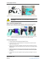
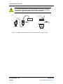
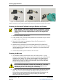
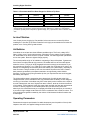
Digital PicoView® 450
Nanospray Ion Source
For AB SCIEX Mass Spectrometers
Hardware Manual
DOCUMENT: DPV45016215
RELEASE DATE: 06/11/15
Read This First
Read This First
This document is provided to customers who have purchased New Objective equipment to use in
the operation with appropriate analytical equipment. This document is copyright protected and
any reproduction of this document or any part of this document is strictly prohibited, except as
New Objective may authorize in writing.
Software that may be described in this document is furnished under a license agreement. It is
against the law to copy, modify, or distribute the software on any medium, except as specifically
allowed in the license agreement. Furthermore, the license agreement may prohibit the software
from being disassembled, reverse engineered, or decompiled for any purpose.
Portions of this document may make reference to other manufacturers and/or their products,
which may contain parts whose names are registered as trademarks and/or function as
trademarks of their respective owners. Any such use is intended only to designate those
manufacturers’ products as supplied by AB SCIEX for incorporation into its equipment and does
not imply any right and/or license to use or permit others to use such manufacturers’ and/or their
product names as trademarks.
New Objective makes no warranties or representations as to the fitness of this equipment for any
particular purpose and assumes no responsibility or contingent liability, including indirect or
consequential damages, for any use to which the purchaser may put the equipment described
herein, or for any adverse circumstances arising therefrom.
For research use only. Not or use in diagnostic procedures.
The trademarks mentioned herein are the property of New Objective, Inc. All other trademarks
are the property of their respective companies.
New Objective, Inc.
2 Constitution Way
Woburn, MA 01801 USA
888 290 2998 Sales
781 933 9560 Phone
781 933 9564 Fax
www.newobjective.com
® 2014 New Objective, Inc. All rights reserved.
®
Digital PicoView 450
2 of 2
User Manual
DOCUMENT #DPV45016215
Read This First
Limited Warranty
DISCLAIMER
Technical information contained in this publication is for reference purposes only and is subject to
change without notice. The information is believed to be reliable and accurate; however, nothing
set forth herein constitutes a warranty of any kind or nature. Given the variety of experimental
conditions, New Objective, Inc., cannot guarantee performance at a given flow rate; the best
guide to tip selection and operation is empirical testing.
The user is solely responsible for complying with any patent(s) pertaining to applications or
methods using the products described or mentioned in this manual.New Objective, Inc., warrants
this Product (Digital PicoView®) to be free of defects in materials and workmanship for a period
of one (1) year from the date of shipment. Any item believed to be defective within the meaning of
the foregoing sentence shall be returned to New Objective, Inc., and, if found by us to be
defective, shall be repaired or replaced with conforming Product of like kind. Please note that a
Return Merchandise Authorization Number (RMA) will be required. New Objective, Inc., will pay
return freight on unsatisfactory items. New Objective, Inc., shall have no other liability or
obligation with respect to goods alleged to be defective. The foregoing shall constitute the sole
and exclusive remedy, and New Objective, Inc.’s total liability for any and all losses and damages
arising out of any cause whatsoever (whether such cause be based in contract, negligence, strict
liability, other tort, or otherwise) shall in no event exceed the purchase price of the Product(s) in
respect of which the cause rose. New Objective, Inc., disclaims, and shall not be liable, in any
event, for loss of profits, consequential or incidental damages, or punitive or exemplary damages
in connection with the Product furnished hereunder.
The foregoing limited warranty (i) shall be void as to any item of Product which is in any material
respect altered by the user, and (ii) does not cover misuse of the Product (for example, but not
limited to, dropping or other mishandling of any components of PicoView, improper trimming of
SilicaTips™, PicoFrit® Columns, or TaperTips™, damage caused by application of or exposure
to excessive temperature, pressure, or voltage) or SilicaTip, PicoFrit, or TaperTip failure by
reason of clogging.
Trademarks
The following trademarks are found in this instruction manual:
Teflon is a registered trademark of E.I. du Pont de Nemours and Co.; QTrap, and TripleTOF are
trademarks of AB SCIEX Pte Ltd. or their respective owners; MicroTight and SealTight are
trademarks or registered trademarks of Upchurch Scientific, Inc. a division of IDEX Corporation;
PEEK and PEEKsil are trademarks of Victrex plc; PicoView, Digital PicoView, PicoClear, PicoTip,
PicoTip Powered, PicoFrit, IntegraFrit, SilicaTip, TaperTip, and GlassTip are trademarks or
registered trademarks of New Objective, Inc. All other trademarks are the properties of their
respective companies.
®
Digital PicoView 450
3 of 3
User Manual
DOCUMENT #DPV45016215
Technical Specifications
Technical Specifications
PicoView Main Unit
Type of Use:
Indoor use only
Operating Conditions:
Normal – 5º - 40º C, 2000 m max, 80% to
temperatures up to 31º C decreasing
linearly to 50% rH at 40º C
Dimensions:
40.54 cm x 30.48 cm x 25.40 cm / 16” x
12” x 10” (packaged)
Weight:
4.9 kg / 11 lbs.
RoHS Compliant:
Yes
260698
Power Usage & Requirements
LED Illuminator:
Stage Actuators:
Digital Divert box:
Digital Camera:
100-240 VAC, 120W, 50/60Hz, 1.2A (max)
100-240 VAC, 50/60Hz, 1.2A (max)
100-240 VAC, 50/60Hz, 1.0A (max)
5V VAC, 500 mA USB 2.0
Please contact New Objective for any information not contained
herein.
®
Digital PicoView 450
4 of 4
User Manual
DOCUMENT #DPV45016215
Safety Considerations
1. Safety Information
Labels on the Nanospray Ion Source and in this Manual
In accordance with regulatory requirements, all warning labels displayed on the ion source are
documented in this guide. Warnings and labels on the ion source use international symbols.
WARNING: This symbol indicates a warning of electrical shock hazard.
Read the warning and follow all precautions before performing any operation
described in the manual. Failure to do so can result in serious injury.
WARNING: This symbol indicates a warning of potential burns from
hot surfaces. Read the warning and follow all precautions before performing
any operation described in the manual. Failure to do so can result in serious
injury.
WARNING: This symbol indicates that ANSI-approved safety glasses
should be worn to protect eyes in the use of indicated equipment and/or
related operations. Failure to do so can result in serious injury.
WARNING: This symbol indicates that ANSI-approved rubber gloves
rated for laboratory use should be worn when handling chemicals or when
working with items that are impacted by handling. Failure to do so can result in
serious injury or cause damage to equipment.
WARNING: This symbol indicates a warning of potential injury to
persons operating the instrument. Read the warning and follow all precautions
before performing any operation described in the manual. Failure to do so can
result in serious injury.
IMPORTANT: This symbol indicates that the information presented is
beneficial to the operation of indicated equipment
®
Digital PicoView 450
5 of 5
User Manual
DOCUMENT #DPV45016215
Safety Considerations
Safety Considerations
WARNING: Electrospray ionization involves the use of potentially
lethal high-voltage electrical current. Observe all manufacturers’ safety
recommendations in the use of such equipment. No equipment modifications
should be made except by trained personnel using methods approved by the
manufacturer in accordance with all safety requirements. Installation of
equipment should be performed by qualified personnel in accordance with all
applicable electrical codes.
WARNING: Never use this product with defective, damaged, or faulty
equipment. Serious injury or death could result.
WARNING: Only qualified personnel should use this product. Provide a
safe workplace equipped with all necessary safety equipment.
Prior to Installation
Follow all safety recommendations of the equipment manufacturer(s). All system voltages must
be brought to ground potential and all high-voltage contacts disconnected from the inlet system
before installation of the PicoView system.
Inspect all equipment carefully prior to use. Any damaged, chipped, or cracked components
should not be used and must be discarded or repaired.
Handling Fused-Silica Tubing
WARNING: Handling of fused-silica or glass tubing and tips can
result in serious personal injury, including eye and skin injury. Use safety
glasses or goggles meeting ANSI Z87.1-1989 requirements, or the equivalent.
Puncture- and chemical-resistant gloves should also be worn at all times.
Tip Adjustment and/or Replacement
Do not attempt to adjust or replace the tip unless the ESI high voltage and other applicable
voltages are turned off and are at ground potential.
®
Digital PicoView 450
6 of 6
User Manual
DOCUMENT #DPV45016215
Safety Considerations
WARNING: Reduce any applicable backing pressure (liquid, gas, etc.)
to ambient before loosening ESI tip fittings and removing the fused-silica tip or
transfer line from the coupling union. Prior to pressurization, make sure that
components are tightened to specifications to prevent separation during use.
Failure to adhere to this warning could result in projectile-like expulsion of the
tip from the coupling union, which could cause serious personal injury or
damage to surrounding apparatus.
The Transfer Line
WARNING: The transfer line connecting to either a tip module or the
Micro Injection Valve must not be made from an electrically conductive
material. It must be fabricated from an electrically insulating material such as
PEEK™ or fused silica. Otherwise, the operator may be exposed to potentially
lethal voltage.
In systems where high voltage is applied directly to the ESI tip, the liquid sample inside the tip
and transfer line tubing is also raised to a high voltage. To prevent exposure to potentially lethal
voltages, a suitable ground point for the liquid inside the line must be provided.
WARNING: Do not defeat any mass spectrometer system software or
hardware safety interlocks.
®
Digital PicoView 450
7 of 7
User Manual
DOCUMENT #DPV45016215
Components
2. Applications
®
Digital PicoView supports a variety of operating modes, ranging from continuous infusion
at nanospray flow rates to gradient run nanobore LC-MS. The uncoated tip module (UTM)
of the Digital PicoView system affords the user the versatility to design experiments for a
variety of flow rates and sensitivity requirements. With this flexible design, you can run the
same analysis several different ways. This manual provides the most robust configurations
for a given application. Following the schematic drawings, locate the desired application
and the most effective PicoView configuration for that experimental design. See the
referenced section for detailed directions on setting up Digital PicoView. Techniques to
®
optimize your spray, including how to select the best PicoTip for your application, can be
found in Section 6.
Continuous-Infusion Nanospray
Continuous infusion is the most straightforward method for sample introduction, with a
syringe pump providing the solvent stream as illustrated in Figure 2.1. Sample is introduced
directly from a syringe pump, at flow rates typically of 10–300 nL/min. The high voltage is
®
applied through the uncoated tip module (UTM) to the PicoTip . Suggested tip sizes for
continuous-infusion nanospray are 5–10 µm with no conductive coating necessary. All tips
should be handled with care. Use a pair of fine tweezers to handle the tips.
Figure 2.1 Continuous-infusion nanospray
Nanospray Flow-Injection
Nanospray flow-injection entails injecting small volumes of sample into an established
solvent stream, as depicted in Figure 2.2. An aliquot of sample (1–2 µL) is injected as a
plug into the solvent stream through the micro injection valve sample loop. A syringe pump
at flow rates of 10–300 nL/min is used to deliver the solvent stream that pushes the sample
through the PicoTip. The flow-injection mode allows for smaller sample sizes than
continuous infusion. This type of experiment is particularly useful for the rapid analysis of
desalted samples. Voltage application for nanospray flow-injection is accomplished using
the uncoated tip module (UTM). SilicaTips in particular are recommended with no
conductive coating (those with -N- in their item number).
Figure 2.2 Nanospray flow-injection
®
Digital PicoView 450
8 of 8
User Manual
DOCUMENT #DPV45016215
Components
Microspray Flow-Injection
Microspray flow-injection, as with nanospray flow-injection, entails injecting small volumes
of sample into an established solvent, as diagrammed in Figure 2.3. The difference
between the two is the flow rate. Nanospray flow rates are typically below 300 nL/min,
whereas the higher microspray flow rates are typically between 0.5–5 µL/min. Sample is
introduced as a plug into the solvent stream from an HPLC pump or syringe at flow rates of
400–5,000 nL/min. The Microspray flow-injection is particularly useful for the rapid analysis
of desalted samples. Using a TaperTip™, a type of PicoTip, voltage is applied through the
liquid junction-style contact of the uncoated tip module (UTM). For the most robust setup, it
is recommended to use uncoated TaperTips with an inner diameter of 20 µm.
Figure 2.3 Microspray flow injection
Nanobore LC-MS Using a PicoFrit® Column
®
Digital PicoView is ideal for performing nanoscale LC-MS and LC-MS/MS using PicoFrit
Columns. PicoFrit Columns, are nanobore LC-MS chromatography columns with an
integral tip, used at flow rates of 100–500 nL/min. In this configuration, the high voltage is
applied to the back of the column through the liquid junction in the uncoated tip module
(UTM). Solvent is delivered via a conventional HPLC pump with a flow splitter or through a
nano-HPLC pump. Suggested tip size is 10 µm with an uncoated PicoFrit column.
®
Figure 2.4 Nanobore LC-MS using a PicoFrit column
Nanobore LC Using a PicoTip® with a Separate Column
®
Digital PicoView can be used effectively for microscale LC-MS and LC-MS/MS. When
®
running nanoscale separations it is best to use a PicoFrit column, a combined emitter and
column, for increased sensitivity and decreased problems due to less plumbing and
connections. If experimental parameters do not allow use of a PicoFrit Column, Digital
®
PicoView can accommodate a nanobore column connected to a PicoTip . New Objective
®
Digital PicoView 450
9 of 9
User Manual
DOCUMENT #DPV45016215
Components
offers IntegraFrit™ Columns designed specifically for this purpose. In this application it is
recommended to use the SilicaTip style of PicoTip. Sample flows through the IntegraFrit,
through the SilicaTip™, and into the mass spectrometer (Figure 2.5). Voltage is applied
through the liquid junction betwen the IntegraFrit and SilicaTip. For a 75 µm ID column, the
suggested tip size is 10 µm with an uncoated tip.
®
Figure 2.5 Nanobore LC-MS using a PicoTip with a separate column
Supplying Voltage to the Uncoated Tip Module
When using the UTM, high voltage is applied directly to the solvent stream in a liquid
®
junction via an electrode. Digital PicoView offers different styles of electrodes to create a
liquid junction and charge the solvent stream: a microtee made of PEEK™ polymer that
contains an integral platinum electrode, a stainless steel union with lower interior volume
(approx. 7 nL), and a step-down union [INSERT DESCRIPTION]. Both are included in the
Digital PicoView accessory box. Figure 2.6 shows both assemblies. The swept volume of
the microtee is approximately 29 nL. For applications requiring lower post-column volume,
the Valco stainless steel union is provided. The internal volume of the stainless steel union
is less than 7 nL. The Valco union uses PEEK fittings designed specifically for 360 µm OD
tubing. These fittings are not compatible with tubing having an OD other than 360 µm.
Figure 2.6 Stainless Steel union in holder (left); Microtee (right)
®
Digital PicoView 450
10 of 10
User Manual
DOCUMENT #DPV45016215
Components
3. Components
Components of Digital PicoView®
®
Figures 3.1A and B illustrate the general layout of Digital PicoView components. The
translation stage and stage plate comprise the Digital PicoView hardware used for
mounting and aligning emitters with respect to the orifice on the mass spectrometer.
DPV-450 Chassis
17
1
19
18
14
15
2
16
3
21
21
4
11
20
13
8
6
5
7
10
10
12
9
Figure 3.1 DPV-450 chassis
Item
1
2
3
4
5
6
7
8
9
10
11
12
13
Description
High-contrast curtain plate
Rinsing station
Safety shield
Camera mounting ring
Digital camera
Camera USB cable
Base plate
Magnetic stage plate
Rail lock bolt
Mounting rails
XYZ stage
Actuator Y
Actuator X
®
Digital PicoView 450
11 of 11
User Manual
DOCUMENT #DPV45016215
Components
Item
14
15
16
17
18
19
20
21
Description
Fiber optic cable
Fiber optic coupler (coupler factory installed)
Illuminator mount
Actuator Z
Voltage module
Nebulizer gas module
Rinse basin
Locking levers (open position)
DPV-450 Interface Ring
7
1
2
8
3
8
4
6
5
5
9
Figure 3.2 Interface ring
Item
1
2
3
4
5
6
7
8
9
Description
Interface ring
Rinsing station
Safety shield
Rinse catch basin
Mounting rails
Interlock pin port
Gas port
Locking levers (open position)
Rinse catch basin drainage nozzle
®
Digital PicoView 450
12 of 12
User Manual
DOCUMENT #DPV45016215
Components
Camera Controls
3
1
2
4
5
Figure 3.3 Camera mount and controls
Item
1
2
3
4
5
Description
Zoom control knob
Pan control knob
Tilt control knob
Camera mounting ring
Zoom control knob lock
Voltage Module Configurations
Sheath Gas Tee
Cover
Locking Screw
To Autosampler,
LC or LC Column
HV Connection
Figure 3.4 DPV-450 UTM (Uncoated Voltage Module)
®
Digital PicoView 450
13 of 13
User Manual
DOCUMENT #DPV45016215
Components
PicoFrit Column
Microtee
To Autosampler
or LC
HV Connection
Figure 3.5 DPV-4500 UTM plumbed with microtee
SilicaTip or
TaperTip
Steel Union
To LC Column
HV Connection
Figure 3.6 DPV-450 plumbed with metal union
Uncoated Tip Module
®
The uncoated tip module (UTM) included with the Digital PicoView system affords the user
the versatility to design experiments for a variety of flow rates and sensitivity requirements.
The module supplies the high voltage for sample ionization through a liquid-junction style
contact, providing rugged and reliable voltage application. The UTM is magnetically
mounted on the stage plate during operation, providing tool-free experimental setup.
Within the uncoated tip module (UTM), the transfer line connects to the emitter via a
modified microtee or through a stainless steel union. High voltage is applied to the liquid
junction via either the platinum electrode in the microtee or through the body of stainless
steel union. Refer to Section 2, “Supplying Voltage” to learn which electrode is best for your
®
application. The UTM provides an optimal interface for PicoFrit columns to afford
purification, concentration, and separation of analytes at high sensitivity. The UTM can also
®
be configured to connect an uncoated PicoTip to a nano- or capillary-bore LC column.
®
Digital PicoView 450
14 of 14
User Manual
DOCUMENT #DPV45016215
Components
WARNING: Turn off or disconnect all power prior to performing any
service on Digital PicoView or any devices attached to it to avoid
potentially lethal electrical voltages.
WARNING: Always use chemical- and puncture-resistant gloves and
ANSI-approved safety glasses when handling fused-silica tubing.
Digitally-Controlled XYZ Positioning Stage
®
Precise alignment of the tip is accomplished using the Digital PicoView PV Acquire™
software and the actuated X, Y, and Z translation stage. The translation stage moves the
stage plate, on which a tip module is mounted. Consult the provided Digital PicoView PV
Acquire Software Manual for more information regarding the stage operation and
specifications.
Imaging System
The imaging system allows the user to quickly and efficiently optimize the electrospray
conditions by providing direct observation of the character of the spray. The system
includes a high-resolution CCD camera and an objective lens. Alignment of the imaging
system is accomplished using the Focus, Tilt, and Pan adjustment screws of the optical
stage (refer to Figure 3.1C).
®
Digital PicoView 450
15 of 15
User Manual
DOCUMENT #DPV45016215
Installing Digital PicoView
4. Installing Digital PicoView®
There are five primary steps involved in installation:
®
Step 1. Mount the Digital PicoView onto the mass spectrometer
Step 2. Install the Stage Control System
Step 3. Install the Imaging System
Step 4. Connect Digital Divert™ Components (optional)
Step 5. Install PV Acquire™ PicoView Software Components (Refer to the Digital
PicoView Software Manual for software installation)
Preparing the Mass Spectrometer
Before installing Digital PicoView, the mass spectrometer must be put into standby mode
and the standard source must be removed if installed.
IMPORTANT: your mass spectrometer must be nanospray-capable with
the AB SCIEX nanospray interface components installed. Please refer to
your AB SCIEX system documents for more information.
Place the Mass Spectrometer into Standby Mode
Refer to your operator manual provided by AB SCIEX for specific information regarding
your system.
Remove Existing Source
Disconnect any transfer lines, voltage connections, gas lines,etc. and remove the existing
source from your system. Be sure to store the existing source in a dry, clean location.
Replace the Curtain Plate
Digital PicoView provides a high-resolution digital view of the nanospray emitter tip and
spray. To enable the best possible imaging, a high-contrast curtain plate is supplied which
allows for high-contrast and minimized reflection.
CAUTION: The curtain plate may be hot. Wear heat-resistant gloves or
allow the system to cool before proceeding with the installation.
®
Digital PicoView 450
16 of 16
User Manual
DOCUMENT #DPV45016215
Installing Digital PicoView
Remove the existing curtain plate by grasping it firmly and pulling the curtain plate away
from the mass spectrometer (Figure 4.1). Refer to your AB SCIEX system manual for
instructions on how to properly remove the curtain plate.
Figure 4.1 Remove the standard curtain plate from the nanospray interface (4000 shown)
Install the high-contrast curtain plate by aligning the curtain plate on the instrument and
pushing it into place (Figure 4.2)
Figure 4.2 Install the high-contrast curtain plate onto the mass spec
Step 1: Attach Digital PicoView to the Mass Spectrometer
The source ring is used to secure the instrument-end of Digital PicoView to the detector
face plate on the front of the mass spectrometer. Digital PicoView is equipped with a safety
shield to prevent accidental contact with potentially high-temperature and high-voltage
components during operation.
1. Locate the Digital PicoView interface ring (see Figure 3.2).
2. Be sure that the locking levers are open and pointing up (see Figure 3.2)
®
Digital PicoView 450
17 of 17
User Manual
DOCUMENT #DPV45016215
Installing Digital PicoView
3. Align the two guide pins on the source ring with the holes on the mass
spectrometer interface (Figure 4.3). Carefully push the source ring towards the
mass spectrometer until it is flush against the instrument panel.
Figure 4.3 Mounting the interface ring onto the mass spectrometer
4. Lock the source ring to the instrument by rotating the locking levers (Figure 3.2)
180º so that they are pointing down. The source ring should now be firmly locked to
the instrument panel.
5. Free the nebulizing gas tube by removing the twist tie from the bundled tubing.
Figure 4.4 Free the nebulizer gas tubing
6. Locate the Digital PicoView source. Remove the protective cover from the interface
pin located on the instrument-facing side of the source (Figure 4.5).
®
Digital PicoView 450
18 of 18
User Manual
DOCUMENT #DPV45016215
Installing Digital PicoView
Figure 4.5 Remove the interlock pin cover before mounting the source to the source ring
7. With the instrument-facing side of the source facing the instrument, align the two
mounting through-bores on the PicoView source with the mounting rails on the
source ring and slide the PicoView source onto the source ring (Figure 4.6). Push
the source as far forward–towards the instrument–as it will go.
Figure 4.6 Slide the source onto the source ring rails. Push source as far forward as possible.
8. Locate the rail lock bolt (refer to Figure 3.1) located in the PicoView accessories
box. Screw this bolt into the right-side rail of the PicoView source ring. This
prevents the source from accidentally sliding off of the source ring.
Figure 4.6 Insert the rail lock bolt into the right-hand rail after mounting the source
9. The XYZ stage is locked to prevent damage during shipping. Remove the shipping
bolt and tube using an appropriate hex wrench (Figure 4.7). Retain bolt and tube in
the accessories box in the event that the unit needs to be shipped in the future.
®
Digital PicoView 450
19 of 19
User Manual
DOCUMENT #DPV45016215
Installing Digital PicoView
Figure 4.7 Remove the shipping bolt and tube
10. Once the stage has been freed and the rail lock screw is in place, slide the
PicoView source away from the mass spectrometer along the rail to continue
installation of the control system.
Step 2: Install the Stage Control System
The stage control system is comprised of three high-precision stepper motor actuators, a
single power supply for the actuators, and USB cabling to connect the system to the mass
spec PC. Refer to Figure 3.1A for actuator references.
The Digital PicoView actuators are very sensitive to mishandling and
impact. Use the utmost care in handling actuators until securely installed
on your Digital PicoView system. Physical damage to actuators due to
dropping or mishandling is not covered under warranty.
1. Locate the three actuators supplied with Digital PicoView. Each actuator is labeled
X, Y, and Z for sequential installation. The stage will not function properly if
actuators are not installed according to instructions.
2. Install Actuator X first. The actuator ports on the XYZ stage are labeled with
corresponding letters. Locate the X-axis port (on the left side of the PicoView
source). Grasp the stage head and gently move the stage slightly against the
spring tension away from the port (Figure 4.8). Insert the lead screw shoulder of
Actuator X through the opening on the port. Be sure that the actuator shoulder
rests snugly against the collar and orient the actuator so that the green LED light is
easily visible.
®
Digital PicoView 450
20 of 20
User Manual
DOCUMENT #DPV45016215
Installing Digital PicoView
Figure 4.8 Insert actuator X into the stage collar marked X. Gently pull the stage head away from the
collar to allow the actuator body to but up to the collar.
3. Using an appropriate hex wrench, tighten the collar lock screw to lock the actuator
into place. Again, you may need to manually adjust the stage to accommodate
positioning for installation. DO NOT let go of the actuator until you have confirmed
that it is secure.
4. Repeat this process for Actuator Y, gently pushing the XYZ stage head forward to
insert the actuator into the stage port. Tighten using the hex wrench (provided).
5. Use the hex wrench to lock it into place. DO NOT let go of the actuator until you
have confirmed it is secure.
6. Lastly, repeat process for Actuator Z , gently lifting the XYZ stage up to insert the
actuator into the stage port (Figure 4.9). Tighten using the hex wrench. DO NOT let
go of the actuator before confirming that it is locked into place.
Figure 4.9 All three stage actuators installed
Make all actuator and camera installation connections prior to connecting
PicoView components to your PC.
7. Daisy-chain connect the X actuator to the Y actuator to the Z actuator by
connecting the color-coded cables, one to another; red to red and blue to blue. The
Z actuator will have an open connector when properly connected.
8. Locate the actuator coupling cable components (Figure 4.10). This includes a 15’long, split-end cable that supplies power and transfers data to and from the motors.
Connect the coupling cable (yellow) to the X actuator cable (yellow). DO NOT
connect to the PC at this time.
®
Digital PicoView 450
21 of 21
User Manual
DOCUMENT #DPV45016215
Installing Digital PicoView
Figure 4.10 Actuator coupling cable components (left). Connect the coupling cable to the X actuator.
The female (or second) cable on the Z-axis actuator should be left
unconnected.
Step 3: Install the Imaging System
Digital PicoView is equipped with a high-magnification digital camera and an optimized
illumination system to provide the highest quality spray and tip imaging possible.
Figure 4.11 Attach the lens tube to the camera body (left). Orient camera as shown (center) and
insert lens tube through camera mounting ring. Connect USB cable (right).
Installing the Digital Camera
1. Locate the digital camera supplied with Digital PicoView.
2. Locate the lens tube in the accessories box. Screw the tube onto the front of the
digital camera (Figure 4.10).
3. Using a 2.5 mm hex wrench (supplied), loosen the camera mounting ring (refer to
Figure 3.1A) lock screw so that the barrel of the camera lens can be easily inserted
without force.
4. Rotate the camera in the mounting ring so that the logos are on the left and right
sides (see Figure 4.11A). The shoulder of the camera lens should rest fully against
the slip ring.
5. Using the same hex wrench, tighten the slip ring screw just until tight. Do not overtighten.
®
Digital PicoView 450
22 of 22
User Manual
DOCUMENT #DPV45016215
Installing Digital PicoView
6. Locate the 15’ USB cable (supplied). Plug one end into the USB socket on the
back of the camera (Figure 4.11B). DO NOT connect to the PC at this time.
Mounting the Fiber Optic Illuminator
The fiber optic illuminator provides an intense method of illuminating the spray without heat.
Figure 4.12 Fiber optic cable (left); Insert fiber optic into the illuminator mount on Digital PicoView
(center); Tighten thumb screw to secure fiber optic in place (right)
Figure 4.13 Fiber optic cable installed in illuminator mount (left); Insert fiber optic coupler into
illuminator (center); Tighten the thumb screw to secure the coupler in place (right)
1. Place the illuminator itself within approximately 5’ of the Digital PicoView source.
The top of the mass spectrometer is most common.
2. Attach the power cable into the appropriate socket on the back of the illuminator.
Plug the opposite end into an appropriately grounded standard power outlet.
3. Locate the fiber optic coupler and cable from the illuminator box.
4. Insert fiber optic coupler into the illuminator mount and tighten thumb screw to
secure. The coupler holds a lens which focuses the illumination on the nanospray
emitter and can be adjusted to accommodate for tip position using the adjustment
knobs (see Figure 3.3).
5. Insert the opposite end of the fiber optic cable into the ring mount on the illuminator
(see Figure 4.13). Tighten the thumb screw to lock the cable in place.
®
Digital PicoView 450
23 of 23
User Manual
DOCUMENT #DPV45016215
Installing Digital PicoView
Step 4: Install Digital Divert™ Components (optional)
Digital Divert™ controls the stage and emitter positon between two preprogrammed points
via contact closure. When one of these programmed positions is the rinsing station, your
emitter or column tip can be kept clean as well as from drying out in between runs. The
rinse station tubing is pre-installed. The reservoir is a simple gravity-driven supply fed
through a supply tube to the rinse station. A preferred mobile phase can be utilized as
rinsing agent, such as 50% MeOH. Refer to the Digital PicoView Software Manual for more
information on using Digital Divert.
The Digital Divert Control Interface must be installed for remote
positioning control by means of contact closure or digital input from a
separate control instrument, usually the LC. Please refer to your LC
manual for more information.
Install Rinsing Reservoir
1. Using an appropriate solvent, wash reservoir bottle prior to use.
2. Fill reservoir with desired solvent for rinsing the exterior of your emitter, such as
50% MeOH/water. Use of acidified water or acetonitrile is not recommended, as
these can damage rinsing delivery and catch basin components.
3. Attach cap to reservoir bottle. The PEEK™ tubing should hang into the bottle, but
should not touch the bottom.
4. Place the reservoir bottle into the stainless steel container fitted with the bottle
collar. Place the reservoir container so that it is positioned higher than the Digital
PicoView source.
5. Prime the PEEK tubing using the supplied syringe (located in the accessories kit)
by pulling liquid from the reservoir.
6. Using the PEEK fitting supplied, connect the plain end of the PEEK tubing to the
rinse station supply connection on Digital PicoView. Connection should be leak
tight.
Install Digital Divert™ Interface Box
1. Connect one end of the supplied serial cable to the back of the digital camera and
the other end to the female connection on the Digital Divert™ Interface Box.
2. Connect the 5V power supply on the side of the Interface Box.
3. Using the bare-wire terminated cable, provided, connect the appropriate wire(s) to
the control instrument. Refer to the user manual supplied with your particular
instrument for specific instructions in making this connection.
®
Digital PicoView 450
24 of 24
User Manual
DOCUMENT #DPV45016215
Installing Digital PicoView
Pin 1 on the interface box is 15V and should be connected to a contact
closure start output. Pin 4 on the interface box is ground and should be
connected to a grounded output on the control instrument.
PIN 1 - CONTACT CLOSURE (+5V) CH 0
PIN 2 - CONTACT CLOSURE (IN+) CH 0
PIN 3 - DIGITAL IN (–) CH 1
9-pin cable
PIN 4 - DIGITAL IN (+) CH 1
control
instrument
+5V plug
DIGITAL CHANNEL (–) CHANNEL 1
DIGITAL CHANNEL (+) CHANNEL 1
DIGITAL CHANNEL (IN–) CHANNEL 0
DIGITAL CHANNEL (+5V) CHANNEL 0
5V supply
digital camera
Figure 4.14 Digital Divert Box interface connections (left); Electrical connections (right)
®
Digital PicoView 450
25 of 25
User Manual
DOCUMENT #DPV45016215
Installing Digital PicoView
5. Setup
Cutting Fused Silica
Proper cleaving of the fused-silica tubing is critical for achieving optimal performance in
nanospray applications. A flat, smooth cut is essential for maintaining low dead volume
connections. Cleaving is best accomplished with a high-quality diamond chip scribe,
available from many chromatography supply houses. New Objective carries a high-quality
scribe as part of a nanospray tool kit (stock number TIP-KIT). Inexpensive carbide or
ceramic scribing tools are not recommended, since they generally result in poor-quality (i.e.,
ragged) cleaved ends, generating fine particles that lead to clogging.
Figure 5.1 Diamond-chip scribe (left); Proper scribe position for cleaving with diamond chip
perpendicular to tubing (center); cleanly cleaved tubing end (right)
1. Place the tubing to be cut on a clean, flat surface and position the cleaving tool
blade perpendicular to the tubing bore, as illustrated in Figure 5.2
2. Press down with a gentle force. DO NOT saw or move the blade laterally; simply
nick the surface of the polyimide coating to score the fused silica. (Figure 5.2 inset)
3. Pull gently on the tubing along its axis; it should easily separate at the point of
scoring. If it does not, repeat the procedure with slightly more force. Be careful not
to force the blade through the tubing, as this will create a ragged end.
Be sure to pull the tubing apart, do not bend the tubing to induce a snap.
This will produce a burr along the tubing face and result in less-thanoptimal connections.
4. It is best to check the cleaved tubing ends for particle contamination prior to
making connections. This is most effectively done using a light microscope at 10x
magnification.
Always select proper ferrules, nuts, and sleeves for the union.
Mismatching of union components will result in spaces with dead volume
or a leaky seal.
®
Digital PicoView 450
26 of 26
User Manual
DOCUMENT #DPV45016215
Installing Digital PicoView
®
Always cleave the fused silica, either tubing or the back end of a PicoTip ,
after pushing it through a sleeve. The fused silica will collect dirt and
particles that were in the sleeve, which, if left in the fused silica, may
cause clogs downstream. Cleaving the fused silica will help prevent
particle contamination.
5.2
Plumbing the Uncoated Tip Module
The uncoated tip module uses a modified microtee or stainless steel union to supply the
high voltage. Which connector you use depends on the application. Refer to Section 2 for
explanations of the two types of junctions and set up instructions. “PicoTip” refers to any of
®,
New Objective’s high-quality tips for electrospray ionization, such as SilicaTips™, PicoFrit
and TaperTips™.
Using PicoFrit® Columns
®
Digital PicoView is ideal for performing nanoscale LC-MS and LC-MS/MS using PicoFrit®
columns. In this configuration, the high voltage is applied to the back of the column through
a liquid junction in the uncoated tip module. The PicoFrit column is packaged as a loop, as
shown in Figure 5.1, to keep both ends of the column at the same pressure during storage
and shipping. Do not remove either the orange-colored PEEK™ sleeve or the snug-fitting
®
FEP (Teflon ) tubing holding the ends of the loop together until the column is being
prepared for installation and use.
There are some important considerations in the handling and use of PicoFrit columns that
make them very different from any other chromatography columns on the market today.
PicoFrit columns are fabricated from 360 µm OD, polyimide-coated, fused-silica tubing. The
column has a specially tapered tip with an integral high-porosity frit. Behind the frit is the
packed chromatography bed. There is no frit at the back end of the bed, only unpacked
fused-silica tubing. Mobile phase flow must always be directed toward the tip. Reversing
the flow may result in partial or complete unpacking of the chromatography bed.
The column is shipped filled with methanol and needs to be conditioned with an appropriate
mobile phase for your gradient. Since there is no distal frit, the distal end of the column bed
may loosen with time; this is not a problem, as the bed will repack when the column is
pressurized.
Refer to the label attached to the opaque orange PEEK sleeve that slides
along the length of the column. The arrow on the label points toward the
tip end. The tip end may also be identified by the charred section of
polyimide coating just prior to the tapered region of the tip.
Removing a PicoFrit® Column from the FEP Sleeve
®
Care must be taken to properly remove the column from the clear FEP (Teflon ) sleeve to
prevent damaging the fragile tip and frit. Use the free-sliding orange PEEK sleeve–assisted
by gravity–to push the clear FEP sleeve off the fused-silica tubing without damaging the tip.
1. Remove the distal end of the column from the FEP sleeve by either pulling it free of
the sleeve or (preferably) by cleaving the fused-silica tubing near the terminus.
2. Slide the PEEK sleeve toward the tip end until it butts up against the FEP sleeve,
as in Figure 5.1.
®
Digital PicoView 450
27 of 27
User Manual
DOCUMENT #DPV45016215
Installing Digital PicoView
3. Orient the FEP sleeve vertically, with the tip facing toward the floor. This way, when
the FEP sleeve slides free, it will fall toward the ground without damaging the tip.
4. Carefully push the PEEK sleeve against the FEP sleeve until the FEP sleeve falls
off, as shown in Figure 5.2. This may or may not take a LOT of force. You will have
to move the PEEK sleeve about 3–5 mm. Grasp the column in one hand while
pushing the sleeve off with the other hand.
5. Once the FEP sleeve falls away, remove the PEEK sleeve by sliding it over the
back end. Do not let the PEEK sleeve slide off the tip end as this will damage the
tip.
Retain the column label for identification purposes.
Figure 5.2 PicoFrit column identified (left); Pushing the PEEK sleeve against the FEP sleeve
(center); Push the FEP sleeve enough to allow gravity to pull the sleeve off of the tip end of the
PicoFrit column
Plumbing the Uncoated Tip Module using PicoFrit Columns
1. Remove lid by loosening thumb screw
2. Insert microtee (located in the accessories box) into recess in base, as shown in
Figure 5.4
3. Remove PicoFrit column from packaging (see Section 5.2.2)
4. Feed the PicoFrit through the front of the sheath gas tee DISTAL END FIRST
taking care to protect the tip from any contact. Slowly pull the entire length through
until the fragile tip is safely inside the sleeve. Tighten the nut on the sheath tee to
secure emitter in place.
5. Continue with plumbing of the microtee or the steel union.
®
Digital PicoView 450
28 of 28
User Manual
DOCUMENT #DPV45016215
Installing Digital PicoView
Figure 5.3 Uncoated tip module – UTM – (left); Microtee inserted into the UTM (center); Feed
emitters and PicoFrit columns distal-end first through the gas tee first before connecting into the UTM
Plumbing the Uncoated Tip Module using an Emitter and Column
®
Digital PicoView 450 requires emitters that are a minimum of 11.5cm in
length. Please be sure to specify either pre-cut SilicaTips (p/n FS360-2010-N-5-11.5CT) or longer length emitters to cleave to this length when
ordering.
1. Remove lid by loosening thumb screw
2. Insert microtee or SS union with holder (located in the accessories box) into recess
in base, as shown in Figure 5.3
3. Remove PicoTip emitter from packaging. Refer to PicoTip instructions for
information on proper handling.
4. Feed the PicoTip through the front of the sheath gas tee DISTAL END FIRST
taking care to protect the tip from any contact. Slowly pull the entire length through
until the fragile tip is safely inside the sleeve. Tighten the nut on the sheath tee to
secure emitter in place.
5. Continue with plumbing of the microtee or the steel union.
Plumbing the Microtee
1. The modified microtee joins the transfer line to the PicoFrit column or, in the
instance of conventional setup, joins the column or transfer line to the PicoTip and
supplies the high voltage. The microtee can be located in the Digital PicoView
accessory box. Orient the microtee as shown in Figure 5.4 so that the platinum
electrode is facing away from the user. Unscrew the nuts and remove the black
ferrules from the posts of the microtee.
Do not loosen the setscrews or remove the electrode cap, as this may
damage the electrode. The solvent will not become charged and an
electrospray will not form. Altering will void warranty.
2. Thread the end of the PicoTip tubing through a green MicroTight sleeve (Upchurch
P/N F-185), which is used for assembly with 360 µm OD tubing. Make sure the
PicoTip does not extend past the tubing sleeve end that will be inserted into the
microtee. Thread the sleeved PicoTip through the fitting nut and a black
MicroFerrule, as shown in Figure 5.8.
®
Digital PicoView 450
29 of 29
User Manual
DOCUMENT #DPV45016215
Installing Digital PicoView
3. Cleave the end of the PicoTip after the tubing is threaded through the sleeve, nut,
and ferrule. Instructions for cleaving fused silica may be found in Section 5.1. Slip
the end of the tubing through the right post of the microtee, as viewed in Figure
5.9A, until the tubing and sleeve seat against the bottom ledge inside the post, as
shown in Figure 5.9B. Screw the nut finger-tight onto the microtee.
Do not adjust
end cap!
Inlet
Outlet
Figure 5.4 Above left; the microtee with sleeves oriented for assembly. Above right; fitting nut,
microferrule and sleeve threaded on to PicoTip emitter. Tip protrudes from the ferrule at left.
A
B
A
B
Figure 5.5 Left; assemble the nut, ferrule, sleeve and emitter as shown in panel A, and secure the
nut finger-tight into the microtee. Right; Assemble the nut, ferrule, sleeve and transfer line as shown
in panel A, and insert into microtee and tighten finger-tight as shown in panel B
4. Insert the distal end of the fused-silica transfer line through a green MicroTight
sleeve, then through the nut and the black MicroFerrule, as shown in Figure 5.10A.
Carefully trim the end of the transfer line. After trimming, insert the assembly back
into the microtee, seat the transfer line, ferrule, and sleeve against the PicoTip, and
finger-tighten the nut, as shown in Figure 5.10B. Gently pull on the tubing ends to
ensure the connection is tight. Check for leaks by running solvent through the
tubing at the expected operating pressure. Leaks will be apparent if solvent collects
at the exposed ends of the sleeves.
Plumbing the Stainless Steel Union
®
This option is not recommended with PicoFrit Columns.
1. Remove the SS union from the PicoView accessories kit. Unscrew the nuts from
the union.
2. Insert 360 µm OD fused silica tubing into the first nut, exposing the tubing beyond
the ferrule (Figure 5.12).
3. Cleave the tubing using the diamond scribe provided (located in the accessories
kit).
®
Digital PicoView 450
30 of 30
User Manual
DOCUMENT #DPV45016215
Installing Digital PicoView
Figure 5.6 Above left: Fully assembled stainless steel union
A
B
4. Insert the assembled tubing/nut combo into the union and tighten the nut while
placing pressure on tubing to ensure proper seating of the tubing. Tighten the nut
until it stops turning (Figure 5.13).
5. Using the provided Valco tightening tool (accessories kit) tighten the nut an
additional ¼ to ½ turn. Gently tug on the tubing to ensure it is properly seated.
6. Repeat with 360 µm OD fused silica tubing on the other side.
7. Once the union is fully assembled insert the union into the SS union holder. Refer
to figure 5.16 if the spring loaded screw needs to be adjusted to insert the union
into the SS holder.
Loading the Assembled Microtee or SS Union into the UTM
8. Lower the assembled microtee or stainless steel union into the cavity in the base of
the UTM. If using the microtee, the warranty label should face forward when the
microtee is properly in place. if desired, an optional mounting screw can be used to
secure the union into the UTM.
9. Replace the UTM module top, being sure to fully seat the lid to the base. Replace
the cover screw through the hole in the module top and align it with the mating hole
in the module base and tighten.
®
Digital PicoView 450
31 of 31
User Manual
DOCUMENT #DPV45016215
Installing Digital PicoView
Alignment of the UTM cover is critical. Misalignment of cover may
damage the internal spring contact mechanism. Make sure cover is
correctly aligned with base before applying pressure and securing cover.
Connecting the High Voltage
Locate the high-voltage cable from the mass spectrometer. Connect the cable to the
appropriate plug on the UTM by pushing it into the cable jack and turning the locking ring
clockwise until it is tight.
Adjusting the Tip Position
By visual inspection, adjust the stage plate position through the PicoView Acquire™ Stage
Control panel (refer to the PV Acquire™ software manual for details) until the tip is
approximately 2–5 mm from the mass spectrometer orifice. Focus the camera using the
focus knob on the optical stage. Instead of focusing on the orifice, focus on the tip, which
may at first appear as a smudged line.
®
Digital PicoView 450
32 of 32
User Manual
DOCUMENT #DPV45016215
Installing Digital PicoView
6. Techniques to Optimize PicoView
This section provides techniques to assure successful use of Digital PicoView®, along with
hints on ways to optimize the spray to consistently generate high-quality data. Also
discussed are the interdependent parameters involved in creating stable electrospray.
Selecting a PicoTip®
Low flow rate ESI (under 1 µL/min) differs substantially from conventional ESI in that signal
levels in the mass spectrometer are more sensitive to solvent composition, flow stability,
and applied voltage. It may take a little time to learn how to obtain consistent results at low
flow rates. A little patience and practice early on can pay off greatly in terms of success.
An effective way to begin working at low flow rates is by starting with larger (15–30 µm) ID
tips and using flow rates at the higher end of the recommended range of operation for a
given tip style. Once you are comfortable working at a certain level of performance, you can
more easily switch to emitters with smaller diameters and operate at lower flow rates.
“PicoTip®” refers to any of New Objective’s high-quality tips for electrospray ionization,
such as SilicaTips™ or TaperTips™. TaperTips are used for higher flow rate applications
and may be a good starting point when learning to work with nanospray. Once basic
performance levels are established, you can switch to SilicaTips with smaller tip sizes. For
highly aqueous mobile phases, however, tip sizes of 10–15 µm and smaller are
recommended.
Select sizes of PicoTips are available pre-cut. A pre-cut emitter has been laser cut and
polished to ensure a flat, clean tubing cut end, This maximizes success in making
connections, reducing the risk of introducing particulates into the flow path.
Choosing a Tip Size
New Objective SilicaTips are available in a full range of sizes from 20µm to 150µm ID with
complimentary tip openings. The DPV-450 Digital PicoView utilizes uncoated PicoTips that
are a minimum of 11.5 cm in length. This length permits the plumbing from the sheath gas
tee to the microtee or voltage application. Always cleanly cleave the distal end of your
emitter as well as any other fused-silica tubing (unless emitters are indicated as pre-cut)
before making connections. Use a pair of fine tweezers to handle the tips.
Uncoated (-N-) PicoTips are required when using a liquid junction-style voltage connection,
typically for nanoscale flow injection applications or when using LC columns larger than 100
µm ID. The choice of tip size will be influenced by the desired flow and application
(continuous-flow nanospray, capillary LC, CE interfacing, etc.). See Section 2 for
assistance in choosing tip size based on the desired application. Since the size of the
Taylor cone grows with flow rate, it is proportional to tip size. Use Table 6.1 as a guide in
choosing the proper tip size.
Follow the flowrate guidelines below to obtain the best results. Smaller diameter tips will
operate most effectively at the lower end of the flow rate range, and larger diameter tips
require higher flow rates to establish a stable spray.
®
Digital PicoView 450
33 of 33
User Manual
DOCUMENT #DPV45016215
Installing Digital PicoView
Table 6.1: Recommended Flow Rate Ranges for Different Tip Sizes
SilicaTip™ Tip ID
Flow Rate
TaperTip™ Tip ID
Flow Rate*
(µm)
(nL/min)
(µm)
(nL/min)
5
20 – 200
20
200 – 500
8
50 – 300
75
300 – 2,000
10
100 – 350
100
400 – 3,000
15
150 – 500
–
–
30
300 – 1,000
–
–
* Approximate range of flow rates over which the tips will generate a stable electrospray plume
without sheath gas assistance. Actual performance may differ due to variations in experimental
parameters (mobile phase composition, applied voltage, etc.). Operable flow rate is a function of tip
size.
In-Line Filtration
Loss of spray due to clogging by fine particles is the most common cause of tip failure.
Installing an in-line filter in the solvent transfer line is highly recommended to minimize this
problem, even if using HPLC-grade solvents.
Air Bubbles
Air bubbles in an emitter have three different possible origins. The first is a leaky HPLC
fitting. A fitting, even if under high pressure, will leak air into the system if liquid is leaking
out. Small leaks, even those in which no liquid is visible, can admit significant quantities of
air into the system. Be sure to tighten fittings properly.
The second possible origin of air bubbles is outgassing of the mobile phase. If gasses are
forced into the mobile phase at high pressure, air bubbles will form as the mobile phase
exists the column. The use of strictly degassed solvents is strongly recommended. If you
are connecting a SilicaTip™ or a TaperTip™ to the outlet of a conventional LC column, air
bubbles from outgassing can adversely affect the stability of the electrospray, especially at
lower flow rates. Using a smaller tip size can also reduce this effect since the increase in
back pressure generated by the tapered restriction can significantly reduce bubble
formation. You may end up using a smaller tip than your required flow rate would suggest,
but stability will improve.
The third possible cause is outgassing due to electrolysis of mobile phase at the highvoltage electrode. As the electrode is at a high potential there are always re-dox reactions
occurring on its surface. Air bubbles may form at the liquid junction interface in the UTM as
a result of electrolysis; the use of higher flow rates, however, tends to minimize the effects
of air bubbles. These relatively higher flow rates match well with the flow rate requirements
of most LC delivery systems. If air bubbles persist and you believe they are due to
electrolysis, the most effective way to completely eliminate the phenomenon is to switch to
a pre-column high-voltage contact with the UTM in combination with a PicoFrit column. The
even backpressure gradient created by the column will eliminate air bubble formation due
to electrolysis.
Operating Parameters
Parameters that require optimization for stable electrospray are the position of the tip with
respect to the orifice, the applied voltage, and the flow rate.
®
Digital PicoView 450
34 of 34
User Manual
DOCUMENT #DPV45016215
Installing Digital PicoView
Tip Position
The transfer of ions created in the electrospray process is maximized when the flow rate is
minimized and when the tip is positioned closest to the mass spectrometer orifice. The
optimal gap between the tip and the orifice varies from 0.5 mm to 5 mm. Too close and the
tip may arc; too far away and the electric field strength drops to a point where the Taylor
cone collapses.
Tuning becomes somewhat difficult at distances less than 0.5 mm due to the large effect on
the spray pattern of relatively small changes in voltage. Most tips can be used at distances
of 2–5 mm with a minimal loss in ion current (under 10 percent). For the majority of
operating conditions, a distance of 1–2 mm appears to be an optimal compromise between
sensitivity and ease of tuning.
Applied Voltage
Applied voltage is perhaps the most important parameter for stable, efficient operation.
Never use a “turn on” voltage above 500 volts unless stable ESI has been previously
established. Direct application of a high voltage (e.g., 2.0 kV) can cause a corona
discharge or an arc between the tip and orifice. This can destroy the conductive coating,
disrupt the fine structure of the tip, and cause the formation of air bubbles within the tip.
Once stable operation has been achieved, however, the voltage can be turned on and off at
the same level with no fear of arcing, provided no other operating parameters have
changed.
Solvent Flow Rate
The optimal flow rate of solvent delivered by Digital PicoView depends on the tubing inner
diameter, the tip size and the applied voltage. A flow rate too low or too high may result in
an unstable spray pattern.
Using a flow rate that is too low leads to large fluctuations in the ion current. Ion current will
likely drop to zero periodically, even frequently. To improve the spray quality, raise the flow
rate by 25 percent and look for an improvement in signal and spray stability.
Using a flow rate that is too high is generally not as problematic; ion current will fluctuate
but will probably not drop to zero. General chemical noise may increase, and the quality of
the mass spectra may be diminished. To minimize the ion current fluctuations, reduce the
flow rate by 25 percent and look for improvements in signal stability. Raising the applied
voltage can sometimes compensate for a flow rate that is too high, provided the voltage is
not above the threshold for corona discharge.
Electric Field Strength and Flow Rate Interdependence
In low-flow ESI, it is important to recognize the interdependence of flow rate and the
applied electric field. The optimal value of the flow rate is altered when a parameter is
changed that affects the “strength” of the electric field (e.g., the size of the tip, the distance
from the tip to the orifice, or the applied voltage).
For a given tip size, stable ESI can occur over a wide range of flow rates but only over a
narrow range of field strength (100 volts or less). Raising the flow rate requires a higher
field strength, and vice versa.
®
Digital PicoView 450
35 of 35
User Manual
DOCUMENT #DPV45016215
Installing Digital PicoView
Voltage Tuning Procedure
For a continuous-infusion experiment, prepare a standard sample and load 100–200 µL
into a 250 µL syringe. Peptide and protein standards should be prepared at 1 µM in a
suitable solvent system, such as 1:1 0.5% acetic acid:methanol. Secure the syringe to the
mass spectrometer syringe pump using the syringe holder.
1. Be sure that Digital PicoView is in operating position by pushing the source as far
forward (towards the curtain plate and orifice) as it will go, taking care that the tip
does not come into contact with the safety shield.
2. Turn on the mass spectrometer and put the mass spec into standby mode.
3. Set the initial ESI voltage to 500 volts.
4. Set the solvent flow rate to a value greater than 100 nL/min.
5. Click “start.”
6. Look on the imaging system monitor to see if solvent is flowing through, forming a
droplet at the tip. If it is, increase the voltage in 100-volt increments until ESI
current is observed. If solvent is not flowing, try increasing the flow rate setting until
a solvent droplet comes into view. If a solvent droplet does not appear, a clog may
have formed. If necessary, change tips.
7. If signal is unstable, increase the voltage in 50-volt increments and look for
improvements in signal stability.
8. If the ion current does not stabilize, optimal field strength has been exceeded.
Lower the voltage 200 volts below the point at which current was first observed,
then raise the voltage in 50-volt increments.
9. The flow rate should be adjusted if stable ESI current cannot be achieved.
10. If no signal is observed, turn off the applied voltage and look for droplet formation
at the tip to visually verify solvent flow-through. If a clog has formed, change the tip.
Do not be concerned if the applied voltage required to generate an electrospray is greater
than that normally required for nano-electrospray methods (e.g., nano-ESI may only require
600 volts for proper operation, while PicoTip® operation using a 15 µm ID may require 2 kV
or more). The applied voltage should still be well below that required for conventional ESI.
Voltages above 4 kV are generally considered excessive with most PicoTips. A corona
discharge may occur if the applied voltage is too high, even when the distance between the
tip and the orifice is large (greater than 5 mm).
Optimizing the Spray
PicoView is ready for use once the tip or column is in position, fluid transfer has been
established, and electrical contact has been made. Bringing the system to stable ESI
conditions will involve adjusting the solvent flow rate and the ESI spray voltage and using
the imaging system to visualize the resulting spray pattern.
®
Digital PicoView 450
36 of 36
User Manual
DOCUMENT #DPV45016215
Installing Digital PicoView
Selecting a Flow Rate
®
The UTM is used most effectively at flow rates above 100 nL/min using PicoFrit columns
at flow rates ranging between 150 and 350 nL/min. The user will need to empirically
determine the best flow rate for each specific experimental design. When using a syringe
pump for delivery, a 100–250 µL syringe is recommended.
To set the flow rate using a syringe pump, access the syringe pump parameter. Set the
flow rate to approximately 0.350 µL/min. Once the spray is established, decrease the flow
rate while adjusting the voltage and tip position (if necessary) until a stable spray is
established at the desired flow rate.
®
Digital PicoView 450
37 of 37
User Manual
DOCUMENT #DPV45016215