1
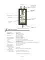
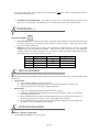
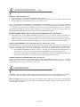
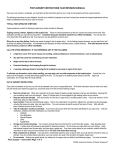
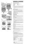
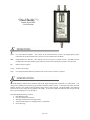
“Dual Buddy” ™ Satellite Signal Meter User Instructions DEFINITIONS LNB: Low Noise Block amplifier. The portion of the antenna-dish that receives the high-frequency signal reflected from the dish and then down-converts it to the L-band (950-2150 MHz). IRD: Integrated Receiver Decoder. Also referred to as the set-top box or satellite receiver. The IRD processes the digital data carried by the RF signal and then provides the baseband picture signal to the television. RF: Radio Frequency signals Cable: 75 Ohm coaxial cable Dish: Oval shaped antenna hardware mounted on the exterior of the customer’s premises. INTRODUCTION The Dual Buddy™ satellite meter measures relative RF signal strength when connected to a dish antenna. It is designed for installing and maintaining typical DBS residential satellite systems. In the balancing modes, the Dual Buddy™ measures two satellite feeds and displays their relative signal strength. The Dual Buddy™ also measures LNB current and the voltage being supplied to the LNBs. It can power LNBs and multi-switches using its internal battery or allow IRD power to run through it. Each Dual Buddy™ package contains: • Dual Buddy™ meter • Protective rubber boot with clip • Wall plug transformer for charging battery • Vehicle power adapter for charging battery in automobile • Instruction page Page 1 of 6 To LNBs Field Replaceable F-81 Double F Female Barrels Measurement Bar Graph LEDs Mode Status LED s Mode Selection Audible Tone ON/OFF LNB/Switch Control To IRD (unless using internal battery) Battery Charger Input SPECIFICATIONS Frequency Range ........................950 to 2150 MHz Impedance ..................................75 Ohm Measurable Input Level .............-48 to –8 dBm total power -60 to –20 dBm per transponder Insertion Loss.............................14 dB (950 to 1450 MHz) 22 dB (1450 to 2150 MHz) Size (HxWxD)/Weight...............6.5” x 2.7” x 1.1”, 1.0 lbs. (16.5 cm x 6.9 cm x 2.8 cm, 455g) Operating Temperature..............0º to 125º F (-17º to 50º C) Connectors .................................F81 Double F female barrel (field replaceable) Power .........................................Uses IRD power when connected, otherwise uses internal battery. IRD voltage loss is 1.3 V. LNB Power ................................Current limited at 600 mA. Internal Battery Pack..................Rechargeable 12 cell NiMH, 350 mAh, 12-16 volts nominal, 10 minute automatic shut off, 1.3 hours typical use per charge. Battery Charge Time ..................12 hours from wall charger Wall Charger Output ..................12 VDC, 200 mA Signal Measure Mode • Signal Level Display..........Bar graph LEDs • Audible Tone......................Dual beep rate with solid tone at peak and when balanced Current/Voltage Mode • LNB current draw ..............0 to 500 mA (each LED segment is 50 mA) • LNB supply voltage ...........10 to 20 volts (each LED segment is 1V, above 9V) Specifications subject to change without notice. Page 2 of 6 OPERATION MODES • SIGNAL STRENGTH: Measures and displays the signal strength on input connector [1]. Each segment of the left LED bar graph is equal to 10 segments of the right LED bar graph. To align the dish for maximum signal strength, obtain the highest possible measurement on the left LED bar graph and use the right side LED bar graph for fine alignment. The measurement displayed is relative signal strength; more is stronger. The numeric value displayed is NOT tied to the IRD’s signal quality value. However, after a few installs, you may learn to correlate the value on the Dual Buddy™ to an approximate IRD value. AUTO RANGING When the Dual Buddy receives a signal greater than the two top segments on the LED bar graphs (99), the unit will automatically switch into an upper scale mode that will allow you to continue peaking the dish. When the Dual Buddy enters this mode, the SIGNAL STRENGTH LED will flash and the signal level displayed will drop to around 70, allowing extra scale to peak the dish. • COARSE BALANCE: Measures and displays the signal strength on input connectors [1] & [2]. The measurement sensitivity is fairly coarse (4 dB per bar). The left LED bar graph corresponds to input [1] and the right with input [2]. You should achieve a peaked and balanced alignment in the COARSE BALANCE mode before going to the FINE BALANCE mode. • FINE BALANCE: Measures and displays the signal strength on inputs [1] & [2]. Because the FINE BALANCE mode is so sensitive (0.8 dB per bar), if you have not previously peaked and balanced the alignment in the COARSE mode, the measurement may be off scale and displayed as a flashing bar (top bar flashing for above scale, bottom bar flashing for below scale). If this occurs, go to the COARSE BALANCE mode to peak and balance the coarse alignment again. • CURRENT/VOLT: Current drawn by the LNB(s) is displayed on the left LED bar graph. Voltage being supplied is displayed on the right LED bar graph. If the Dual Buddy™ detects an over-current situation, it will switch to CURRENT/VOLT mode and flash the highest LED segment on the CURRENT side. LNB power will be shut off except for retesting every 4 seconds. If the Dual Buddy™ detects a voltage from the IRD greater than 20V or less than 10V while in the CURRENT/VOLT mode, it will flash either the highest or lowest LED segment on the VOLT side, respectively. AUDIBLE TONE • Press the audible tone button to turn the tone on or off. There are three tones: slow beep, fast beep and solid. The function depends on the measurement mode: In SIGNAL STRENGTH mode: The audible tone will be a slow beep if not connected to an LNB and a fast beep or solid tone when connected to an LNB. For the audible tone to work correctly, the meter has to “learn” the installation’s maximum and minimum signal level. With the meter connected to the LNB and the audible tone activated, slowly adjust the horizontal (azimuth) dish alignment over a wide left/right sweep. The audible tone will change from a solid tone to a fast beep indicating the meter is “learning and remembering” different signal strengths. After a forward sweep Page 3 of 6 through the peak signal, slowly sweep back until obtaining a solid tone, which will indicate the meter is receiving the maximum signal. • COARSE and FINE BALANCE: The audible tone beeps faster as the signal strength of inputs [1] and [2] get closer to being equal. The audible tone will be solid when the inputs are closely balanced. OPERATION Con’t SWITCH CONTROL • • Normal 22 kHz: While connected to an LNB, a quick push of the 22 kHz button provides a 22 kHz tone to the input [1] connector for controlling 22 kHz switches or universal LNBs. Another quick push of the button turns off the 22 kHz tone. DiSEqC™: While connected to an LNB, push and hold the 22 kHz button for 3 seconds. The Dual Buddy™ beeps and the adjacent LED flashes. With each new press of the button, a new DiSEqC™ command will be sent and the LED flash rate will change to indicate the LNB or switch selection made. The commands are sent on input connector [1] only. Flashes 1 2 3 4 DiSEqC switch A B C D DPP and 1000.2 119° 110° 129° DP 34/44 switch Dish 1 Dish 2 Dish 3 Dish 3 DISH ALIGNMENT Mount the dish and adjust the azimuth, elevation, and skew per the instructions of the service provider and hardware manufacturer. • Single satellite: 1) Connect the Dual Buddy’s input [1] to the LNB. 2) Adjust the dish azimuth until signal strength is maximized on the display or audible tone. 3) Adjust the dish elevation until signal strength is maximized. • Dual Satellite: 1) Connect two cables from the LNB to input connectors [1] and [2]. 2) In SIGNAL STRENGTH mode, adjust the dish until signal strength on input [1] is maximized on the display or audible tone. 3) Select COARSE BALANCE mode and make small adjustments to balance the left (input [1]) and right (input [2]) LED bar graphs or until a solid audible tone is obtained. 4) Select FINE BALANCE mode and make small adjustments to balance the left and right LED bar graphs or until a solid audible tone is obtained. APPLICATION NOTES DIRECTV™ SINGLE SATELLITE: • Follow DISH ALIGNMENT instructions above. Page 4 of 6 APPLICATION NOTES Con’t DIRECTV™ MULTI-SATELLITE: • Dual Cable Input: Follow DISH ALIGNMENT instructions above. • Single Cable Input: Signal received without the 22 kHz tone activated is from the 101º satellite. Signal received with the 22kHz tone activated is from the 119º/110º satellite signal. Note: For North American DIRECTV™ multi-satellite antenna installations, do not try to obtain a perfectly balanced measurement on the Dual Buddy’s ™ LED displays. At the time of printing these instructions, there were 16 transponders measured by the Dual Buddy™ from 101º and only 13 transponders from the 119º/110º satellites. We recommend peaking the 101º feed and then bringing the 119º/110º feed to a level no more than one bar less in the COARSE BALANCE mode and about 3 bars less in the FINE BALANCE mode. ECHOSTAR DPP TWIN LNB (119° and 110°) and 1000/1000.2 (119°, 110° and 129°): • • Dual Cable Input: Follow DISH ALIGNMENT instructions on Page 4. With no switching commands, the cable from the 119º side will carry the 119º signal and the cable from the 110º side will carry the 110º signal. Single Cable Input: Connect a cable from input [1] to either side of the LNB head. Press and hold the 22 kHz button for 3 seconds to enable DiSEqC™ switching. Now, select the LNB according to the table on Page 4. ECHOSTAR SUPERDISH™, three LNBs (DBS 110°/119°, and FSS 105° or 121°): The Dual Buddy ™ can power two LNBs and the switch, but not all three LNBs at the same time. Therefore, it is necessary to work with only two LNBs at the same time. Connect the two outermost LNBs to the Dual Buddy; connect the DBS LNB to input port [1] and the FSS LNB to input port [2]. Perform the following to align the dish: • Follow DISH ALIGNMENT instructions on Page 4. See steps 2 and 3 under the Dual Satellite section to align both outer LNBs. Do not use the FINE STENGTH MODE (Step 4) when aligning this dish. • Disconnect both the DBS and FSS LNBs from the Dual Buddy™. Connect the middle (DBS) LNB to the Dual Buddy’s™ input port [1]. Verify that adequate signal strength is being received. ECHOSTAR LEGACY (DISH 500 TWIN LNB, 110° and 119°): Connect both cables from the LNB head and follow DISH ALIGNMENT instructions on Page 4. The Dual Buddy™ does not control the switch inside the LNB head so the cable from the 119º side will carry the 119º signal and the cable from the 110º side will carry the 110º signal. MAINTENANCE Connectors: The F-81 double F female barrels should be replaced when worn. When changing the F-81 barrels, use a 7/16” wrench. Be careful to protect and align the base connector’s stinger when changing connectors. Battery Charging: While the unit is off, charge it overnight to obtain a full charge. Do not use a wall transformer other than the one provided. Improper voltage or current input may damage the battery charge circuit and require non-warranted service work. Page 5 of 6 MAINTENANCE Con’t Dual Buddy ™ spare parts and associated labor: Description Battery charger wall-transformer Battery charger auto-cigarette charger Protective rubber boot with clip F-81 double female barrel Battery pack Lexan face adhered to metal front panel Top metal end panel Bottom metal end panel (without charge jack) Base connector & cable that receives F-81 Material Labor $5.85 $8.00 $15.00 $2.00 $27.69 $15.00 $3.00 $3.00 $7.00 ------------$5.00 $5.00 $5.00 $5.00 $5.00 Shipping, handling and evaluation fees are extra. Prices subject to change without notice. WARRANTY The Applied Instruments Dual Buddy™ has a limited warranty against defects in materials and workmanship for a period of twelve months. Applied Instruments agrees to repair or replace any assembly or component (except F-connectors, battery, and protective rubber boot) found to be defective under normal use during this period. Applied Instruments’ obligation under this warranty is limited solely to repairing the instrument proved to be defective within the scope of the warranty when returned to the factory. Transportation to the factory is to be arranged and prepaid by the customer. Authorization by Applied Instruments is required prior to shipment. Applied Instruments assumes no liability for secondary charges or consequential damages and, in any event, Applied Instruments’ liability for breach of warranty under any contract shall not exceed the purchase price of the instrument shipped, and against which a claim is made. Any application recommendations made by Applied Instruments for the use of its products are based upon tests believed to be reliable, but Applied Instruments makes no warranty of the results to be obtained. This warranty is in lieu of all other warranties, expressed or implied, and no representative or person is authorized to represent or assume for Applied Instruments, any liability in connection with the sale of Applied Instruments products other than that set forth herein. Please keep your receipt of purchase to verify purchase date. If it becomes necessary to have your Dual Buddy™ serviced, contact: Applied Instruments, Inc. 5230 Elmwood Avenue Indianapolis, IN 46203 USA Tel. (317) 782-4331 Fax (317) 786-9665 www.appliedin.com Revised 3/2007 Page 6 of 6