1
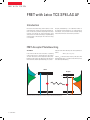
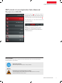
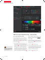
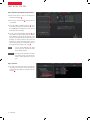
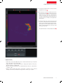
No.44, November 2013 Confocal Application Letter resolution FRET Acceptor Photobleaching LAS AF Application Wizard FRE T with TCS SP8 FRET with Leica TCS SP8 LAS AF Introduction Fluorescence Resonance Energy Transfer (FRET) is a technique which allows insights into interactions between proteins or molecules in proximities beyond light microscopic resolution. The principle: An excited fluorophore, called donor, transfers its excited state energy to a light-absorbing molecule which is called acceptor. This transfer of energy is non-radiative. Acceptor photobleaching is an established method for the evaluation of FRET efficiencies. It is usually applied to fixed samples, as any relocation of donor molecules during measurement will lead to false intensity correlations. FRET Acceptor Photobleaching The method In the event of FRET the donor encounters a quenching of fluorescence due to its energy transfer to the acceptor. The donor fluorescence will be unquenched after photobleaching of the acceptor. The difference in the intensity of the donor before and after photobleaching gives a direct indication of the FRET efficiency and can be quantified as follows: FRETeff = (Dpost - Dpre) / Dpost where Dpost is the fluorescence intensity of the donor after photobleaching and Dpre is the fluorescence intensity of the donor before photobleaching. Donor Acceptor S1 S1 In the event of FRET an excited fluorophore transfers its energy to another light-absorbing molecule. 2 reSolution FRE T with TCS SP8 FRET wizards in Leica Application Suite Advanced Fluorescence (LAS AF) 1 In the LAS AF menu bar 1 you can find two wizards for performing FRET experiments: FRET AB (Acceptor Photobleaching) and FRET SE (Sensitized Emission). This application letter describes work with the FRET AB Wizard 2 . The wizard consists of 3 steps and an overview of the experimental workflow. Step 1 is dedicated to the imaging set-up. Step 2 allows the definition of bleaching conditions. The experiment is executed between Step 2 and 3. Step 3 allows the evaluation of results and generation of experimental reports. 2 General Safety Notes The system and LAS AF may only be used by persons who have been trained in the use of the system and about the potential hazards of laser radiation. Observe the user manual Follow the safety notes and instructions in the user manual. WARNING Permanent eye and skin damage from laser radiation Skin and eye damage can occur while using lasers if safety precautions are not taken. Pay particular attention to the laser safety. Confocal Application Letter 3 fre t WitH tCS Sp8 5 3 6 2 1 7 4 fret acceptor photobleaching – Step by Step Step 1: Setting of experimental conditions Define the imaging conditions for donor and acceptor fluorescence by following the workflow. You may start your experiment with previously saved imaging conditions. Use the Load and Save options 1 . If you want to establish imaging conditions yourself, you must start out in the Beam Path Settings 2 . from this time on, laser radiation may be present in the specimen area of the laser scanning microscope. follow the safety notes in the user manual. 4 resolution 1. Begin by simultaneous excitation and detection of the donor and acceptor. You can load existing settings out of the IPS list 3 , or set up the imaging conditions manually (e.g.: Donor = CFP excitation 458 nm; emission 462-510 nm; Acceptor = YFP excitation 514 nm; emission 518-580 nm). This enables you to optimize the laser excitation dose, PMT gain and detection slider position for each label. It also allows you to judge where you may find donor and acceptor fluorescence and where they coincide. Do all adjustments by using the Live button 4 . Check for appropriate imaging resolution. You may change the zoom factor via the control panel or use the mouse over info at the button in Acquisition 5 . 2. Now follow the workflow and change the imaging conditions to donor detection 6 only by switching off the acceptor detection channel and setting the laser light of the acceptor to 0 %. 3. Start Live Scan 4 for image optimization. 4. Continue by defining the acceptor imaging set-up. Turn the donor excitation light down to 0 %, turn off the donor detection channel, turn on the acceptor detection channel instead and then set the excitation laser line of the acceptor for adequate excitation light. 5. Start Live Scan 4 for image optimization. fre t WitH tCS Sp8 A B C 8 6. If you would like to see both donor and acceptor acquired together, you need to activate the sequential imaging option via checkbox 7 . Image acquisition of donor and acceptor is done in a line-by-line sequential scan mode. 8. Define the number of averages for best image quality with the tools under Acquisition 5 . 9. Proceed to the next step Bleach 8 to define bleaching conditions. 7. The images visible in the viewer are generated by means of line-by-line sequential scan. Images A + B show donor (green) and acceptor (red). The image bottom left shows the overlay of both fluorescence signals C . To display an overlay image, activate this button . The overlay image will help you to choose the appropriate region for acceptor photobleaching. ConfoCal appliCation letter 5 fre t WitH tCS Sp8 Step 2: Define Acceptor Photobleaching Conditions 1. Begin with the choice of laser line and intensity for acceptor photobleaching 1 . 1 2. Draw a region of interest (ROI) 2 around the area you wish to bleach. 2 3. Select the number of bleaching iterations 3 . If you have defined averaging under Acquisition in step 1, this will not apply to the bleaching, so please consider the bleach duration accordingly. 3 4. You may now run the bleaching experiment 4 . The measurement will start by imaging donor and acceptor before bleaching, followed by the bleaching of the acceptor, and end by imaging donor and acceptor after bleaching. The imaging conditions before and after bleaching are identical. Bleaching progress may be followed by the progress bar or bleaching progress in the image and may be stopped if necessary 4 . 4 You may stop the bleaching. The wizard will now finish the experiment by taking the post bleach sequence. You may stop the experiment at this point. This might be useful if the specimen has moved or imaging parameters need to be reset. Step 3: Evaluation 1. The image now shown in the viewer is the FRET efficiency image. The mean values of FRET efficiency within the bleached region (ROI1) are displayed in the user interface 1 . 6 resolution 1 FRE T with TCS SP8 2. You may choose additional regions of interest for better interpretation of results 2 . 2 3. FRET efficiencies may also be estimated via the intensity display in the viewer 3 . The displayed LUT may be changed for better visualization or understanding by clicking on the intensity slider. Color coding for high or low values may be altered by moving the slider ends up and down. This may, for example, set the purple background to black. 4. Saving data: Images are saved via Save As by right mouse click on the experiment in the experiment tree. Regions of interest (ROIs) and images that have undergone changes (e.g. FRET efficiency images with LUT changes or added annotations) are saved by a right mouse click on the viewer. The experimental data is saved by creating a report 4 . 3 4 Suggested reading: • Gadella TWJ, Van der Krogt GNM and Bisseling T, “GFP-based FRET Microscopy in Living Plant Cells”, Trends Plant Sci. 4 (7): 287-291, 1999 • Lippincott-Schwartz J, Snapp E. and Kenworthy AK, “Studying protein dynamics in living cells”, Molecular Cell Biology, 2, 444-456, 2001 • Wouters FS, Verveer PJ and Bastiaens PIH, “Imaging biochemistry inside cells”, Trends Cell Biol., 11(5): 203-11, 2001. • Clegg R, “Förster resonance energy transfer – FRET: what is it, and how it´s done”, Laboratory Techniques in Biochemistry and Molecular Biology, Volume 33. Elsevier. pp. 1-55, 2009. Confocal Application Letter 7 www.leica-microsystems.com The statement by Ernst Leitz in 1907, “With the User, For the User,” describes the fruitful collaboration with end users and driving force of innovation at Leica Microsystems. We have developed five brand values to live up to this tradition: Pioneering, High-end Quality, Team Spirit, Dedication to Science, and Continuous Improvement. For us, living up to these values means: Living up to Life. Leica Microsystems operates globally in three divisions, where we rank with the market leaders. Life Science Division The Leica Microsystems Life Science Division supports the imaging needs of the scientific community with advanced innovation and technical expertise for the visualization, measurement, and analysis of microstructures. Our strong focus on understanding scientific applications puts Leica Microsystems’ customers at the leading edge of science. Industry Division The Leica Microsystems Industry Division’s focus is to support customers’ pursuit of the highest quality end result. Leica Microsystems provide the best and most innovative imaging systems to see, measure, and analyze the microstructures in routine and research industrial applications, materials science, quality control, forensic science investigation, and educational applications. Medical Division The Leica Microsystems Medical Division’s focus is to partner with and support surgeons and their care of patients with the highest-quality, most innovative surgical microscope technology today and into the future. Leica Microsystems – an international company with a strong network of worldwide customer services: Active worldwideTel.Fax Australia ∙ North Ryde +61 2 8870 3500 2 9878 1055 Austria ∙ Vienna +43 1 486 80 50 0 1 486 80 50 30 Belgium ∙ Diegem +32 2 790 98 50 2 790 98 68 Canada ∙ Concord/Ontario +1 800 248 0123 847 405 0164 Denmark ∙ Ballerup +45 4454 0101 4454 0111 France ∙ Nanterre Cedex +33 811 000 664 1 56 05 23 23 Germany ∙ Wetzlar +49 64 41 29 40 00 64 41 29 41 55 Italy ∙ Milan +39 02 574 861 02 574 03392 Japan ∙ Tokyo +81 3 5421 2800 3 5421 2896 Korea ∙ Seoul +82 2 514 65 43 2 514 65 48 Netherlands ∙ Rijswijk +31 70 4132 100 70 4132 109 +852 2564 6699 2564 4163 21 6387 6606 21 6387 6698 People’s Rep. of China∙ Hong Kong ∙ Shanghai +86 Portugal ∙ Lisbon +351 21 388 9112 21 385 4668 Singapore +65 6779 7823 6773 0628 Spain ∙ Barcelona +34 93 494 95 30 93 494 95 32 Sweden ∙ Kista +46 8 625 45 45 8 625 45 10 Switzerland ∙ Heerbrugg +41 71 726 34 34 71 726 34 44 United Kingdom ∙ Milton Keynes +44 800 298 2344 1908 246312 +1 800 248 0123 847 405 0164 USA ∙ Buffalo Grove/lllinois Order no.: English 1593104031 ∙ Copyright © by Leica Microsystems CMS GmbH, Mannheim, Germany, 2013. Subject to modifications. LEICA and the Leica Logo are registered trademarks of Leica Microsystems IR GmbH.