1
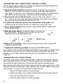
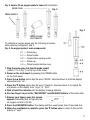
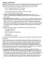
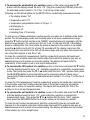
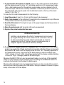
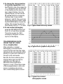
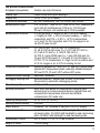
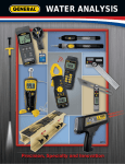
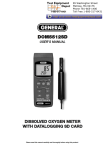
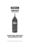
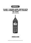
WK2017SD
USER’S MANUAL
pH, ORP, CONDUCTIVITY, TDS,
SALT AND DO METER
WITH DATALOGGING SD CARD
Please read this manual carefully and thoroughly before using this product.
TABLE OF CONTENTS
Introduction . . . . . . . . . . . . . . . . . . . . . . . . . . . . . . . . . 3
Key Features . . . . . . . . . . . . . . . . . . . . . . . . . . . . . . . . 4
Operating Instructions . . . . . . . . . . . . . . . . . . . . . 4 – 16
What’s in the case . . . . . . . . . . . . . . . . . . . . 4 – 5
Setup . . . . . . . . . . . . . . . . . . . . . . . . . . . . . . . 6 – 8
Calibrating a pH Electrode . . . . . . . . . . . . . . 8 – 9
Calibrating the Conductivity/
TDS/Salt Probe. . . . . . . . . . . . . . . . . . . . . . . 10
Calibrating an Oxygen Probe . . . . . . . . . . 10 – 11
Normal Operation . . . . . . . . . . . . . . . . . . . 12 – 14
Holding and Storing Measurements. . . . . . . . . 15
Automatic vs. Manual Datalogging . . . . . 15 – 16
Transferring Data from the SD Card
to a Computer . . . . . . . . . . . . . . . . . . . . . . . 16
Specifications . . . . . . . . . . . . . . . . . . . . . . . . . . . . . . 17
Maintenance & Troubleshooting Tips . . . . . . . . . . . . 18
Optional Accessories. . . . . . . . . . . . . . . . . . . . . . . . . 18
Warranty Information . . . . . . . . . . . . . . . . . . . . . . . . 19
Return for Repair Policy . . . . . . . . . . . . . . . . . . . . . . 19
2
INTRODUCTION
Thank you for purchasing General Tools & Instruments’ WK2017SD pH, ORP, Conductivity,
TDS, Salt and DO Meter with Datalogging SD Card. Please read this user’s manual carefully
and thoroughly before using the instrument.
The WK2017SD is a general purpose handheld instrument capable of measuring the pH,
oxidation-reduction potential (ORP) or conductivity of a solution, as well as its TDS
(total dissolved solids), DO (dissolved oxygen) or salt content. Using an included
conductivity/TDS/salt probe, an optional DO probe, and optional ORP and pH electrodes,
the meter can measure pH from 0 to 14, ORP from -1999 mV to +1999 mV, conductivity
up to 200 mS (milliSiemens), TDS up to 132,000 ppm, DO up to 20 mg/L, and salt content
up to 12% by weight.
The meter also accepts an optional automatic temperature compensation (ATC) probe that
configures a pH electrode to measure solutions at temperatures between 32º and 150ºF
(0º and 65ºC). For measuring the pH of solutions at temperatures between 32º and 212ºF
(0º and 100ºC), the temperature compensation can be set manually. pH electrodes must be
calibrated for pH 4, pH 7 and pH 10 using buffer solutions, as do conductivity/TDS/salt
probes and oxygen probes using their own standard solutions.
Among the applications and environments suitable for the WK2017SD are water
conditioning, wastewater monitoring, beverage production, aquaculture (fish farming),
aquariums, pulp and paper processing, electroplating, and photography.
The WK2017SD has the performance and features needed to satisfy the most demanding
aspects of the above applications. A front-panel pushbutton enables rapid switching among
the meter’s four measurement modes.
Because it is microprocessor-based, the WK2017SD can make full use of the portability,
reliability and large storage capacities that SD memory cards offer. Measurements can be
made automatically at any sampling rate between one second and nine hours. After timestamping and storing the measurements on an SD card plugged into the meter (a process
called datalogging), the user can remove the card and plug it into to a laptop or desktop
computer either directly or via a USB card reader. The data logs are stored on the card as
files with the .xls extension, which can be opened by Microsoft’s Excel application
The WK2017SD has a backlit 2-1/2 in. diagonal display and is powered by six “AA” Alkaline
batteries or an optional 9-VDC AC adapter.
3
KEY FEATURES
• Measures pH, ORP and conductivity, and TDS, salt and DO content using included
and optional electrodes and probes
• Measured parameter can be changed by pressing front-panel buttons
• DO measurements can be compensated for salt, altitude and temperature
• Also measures oxygen content of a volume of air
• Optional ATC probe automatically temperature-compensates pH electrode
• Displays maximum and minimum readings
• Performs real-time automatic datalogging at sampling time settable from
1 second to 9 hours
• Also supports manual logging and changing of card storage location
• Outputs Excel-compatible data logs
• Accepts SD memory cards of up to 16 GB capacity
• Big (2.5 in. diagonal) front-panel green backlit LCD is easy to read
• Auto power off function
• Powered by six “AA” batteries or optional 9V AC/DC adapter
OPERATING INSTRUCTIONS
WHAT’S IN THE CASE
The WK2017SD comes fully assembled in a hard carrying case along with a
conductivity/TDS/salt probe, a 2 GB SD card and this user’s manual.
Optional accessories available from General Tools & Instruments include:
• pH and ORP electrodes
• A probe for automatic temperature compensation (ATC) of pH electrodes
• A DO probe
• pH 4 and pH 7 buffer solutions
• A 1.413 uS (microSiemens) standard conductivity solution
• A probe-filling electrolyte
• A spare DO probe and diaphragm set
• A 9VDC adapter for a 110V power supply
See the Optional Accessories section of this manual for more details.
Figure 1 shows all of the controls and indicators on the front, back, top, bottom and right
side of the WK2017SD. Familiarize yourself with the positions and functions of these
controls, indicators and connectors before moving on to the setup procedure.
4
TOP
FRONT
BOTTOM
RIGHT
SIDE
BACK
Fig. 1. The WK2017SD’s controls and indicators and other physical features
1-1 Liquid-crystal display
1-2 POWER button
1-3 HOLD/ESC button
1-4 REC/ENTER button
1-5 ▲ button
1-6 ▼ button
1-7 TIME button
1-8 LOGGER SET button
1-9 Kickstand
1-10 Battery compartment cover
1-11 Battery compartment cover screws
1-12 Tripod attachment nut
1-13 Socket for ATC temperature probe
1-14 Socket for oxygen probe
1-15 Socket for conductivity/TDS/salt probe
1-16 Socket for pH electrode with
BNC connector
1-17 Socket for 9VDC AC adapter
1-18 Reset button
1-19 RS-232 output jack
1-20 SD card socket
5
SETUP
1. Choose the power source. Before using the WK2017SD, be sure it is powered by fresh
batteries or an optional 9VDC AC adapter plugged into the bottom jack on its right side
(callout 1-15).
To remove the battery compartment cover, remove the two screws holding it in place
(callout 1-11). Then install six “AA” batteries in the correct orientation, using the polarity
marks on the inside of the compartment as a guide. Replace the cover by replacing the two
screws.
2. Install an SD card. To prepare for setup, also install the supplied 2 GB SD memory card
or another card with a capacity from 1 GB to 16 GB capacity in the socket on the bottom
of the meter (callout 1-18). When installing the card, make sure its gold contacts are
facing front and push the card into the socket until you hear a click. To remove the card,
push it in until you hear a click and the card pops out.
Now power on the instrument by pressing the POWER button (callout 1-2) to generate a
short beep. (To power off the WK2017SD, press the POWER button and hold it until the
instrument responds with a long beep.)
When the meter powers on, a series of transient startup screens will briefly appear. Once
the display has stabilized, perform the following 13 setup steps in the order presented.
3. Format the SD card. The first step in the setup procedure determines whether or not to
format the SD memory card plugged into the instrument. Press the LOGGER SET button
(callout 1-8) and hold it for at least five seconds, until “Sd-F” appears in the lower half
of the display. Quickly (within three seconds) press the REC/ENTER button.
(If you press buttons too slowly in setup mode, the screen will revert to the normal display.
To return to the setup sequence, press and hold the LOGGER SET button again. To move
ahead to the next field in the sequence or to the next parameter, press the HOLD/ESC
button.)
Pressing the REC/ENTER button causes the word “no” or “yES” to appear over the term
“Sd-F”. Press the ▼ button to make a selection. Choose “yES” whenever a new SD card is
being used, or when a used card is being repurposed (from use with another SD card
instrument or a camera, for example) and all data on it is to be erased. Choose “no” to
preserve any data on a card previously used with this instrument.
If you choose “yES”, after you press the REC/ENTER button the instrument will prompt you
to confirm that decision by displaying the term “Ent” below “yES” and sounding three
beeps. To confirm that you want to begin the erasure/formatting procedure, press the
REC/ENTER button. “Ent” will then flash several times and the meter will sound another
three beeps to confirm that the SD card has been erased and formatted.
4. Set the date and time. Once the SD card has been formatted, the meter will
automatically move to the next step in the startup sequence: setting the current date and
time. When the word “dAtE” appears in the center of the display, along with the flashing
value “00.00.00” at the lower left, above “yy.mm.dd”, set the current year by pressing
the ▼ or ▲ button repeatedly until the correct value appears above “yy”. Press the
REC/ENTER button to store the setting. The next screen that appears will have the value
6
above “mm” flashing. Use the ▼ or ▲ button to navigate to the current month and press
the REC/ENTER button to store the setting. When the next screen flashes the value above
“dd”, again use the ▼ or ▲ button to navigate to the current day and press the
REC/ENTER button to store the setting.
Once you have set the date, the display will prompt you to set the hour, minute and second
of the current time. Again use the ▼ or ▲ buttons to navigate to the correct values, and the
REC/ENTER button to store the settings.
5. Set the datalogging sampling time. Once the date and time have been set and
stored, the display will show a value below the letters “SP-t”. Press the ▼ or ▲ button
to decrease or increase the flashing hour value until the desired number appears below
“SP-t”. Press the REC/ENTER button to store that setting. The minutes value will then
flash. Press the ▼ or ▲ button to decrease or increase the value and then press the
REC/ENTER button to store that setting. Finally, press the ▼ or ▲ button to decrease or
increase the flashing seconds value and then press the REC/ENTER button to store that
setting.
6. Enable or disable auto power off. Once the sampling time has been set and stored,
the display will show the word “yES’ over the term “PoFF”. Press the ▼ button until the
desired automatic power off management scheme (“yES” for enable; “no” for disable)
is displayed. Press the REC/ENTER button to store the selection. If enabled, the power
off function shuts off the WK2017SD after a period of inactivity of ten minutes.
7. Enable or disable the beeper. Once the auto power off scheme has been chosen and
stored, the display will show the word “yES” over the word “bEEP”. Press the ▼ button
until the desired setting (“yES” or “no”) is displayed, and then press the REC/ENTER
button to store the selection as the default.
8. Choose a decimal point or comma. Once the beep sound has been enabled or
disabled, the display will show the word “bASIC” above the phrase “dEC”. The next step
in the setup sequence determines whether displayed values use a period or a comma
to represent the decimal division between integers and fractions (for example,
American-style 20.88 vs. European-style 20,88). Press the ▼ button to make “bASIC”
(American style) or “Euro” appear in the upper display, as desired. Press the REC/ENTER
button to store the selection as the default.
9. Select the temperature unit. Once the format of decimal point divisions has been set
and stored, the lower portion of the display will show the term “t-CF”. Press either the
▼ or ▲ button to change the letter displayed at the right of the display to “C” (for
Celsius units) or “F” (for Fahrenheit units), as desired. Then press the REC/ENTER
button to store the selection as the default.
10. Set the optional DO probe’s level of compensation for salt in the solution when
operating in DO measurement mode. The default value is 0% by weight. The level of
compensation is adjustable between 0 and 50%. Once the display temperature unit has
been set and stored, the lower portion of the display will show the term “SALt”. Press
either the ▼ or ▲ button repeatedly until the value above “SALt” matches the desired
compensation level. Press the REC/ENTER button to store the setting.
7
11. Compensate for altitude in metric units when operating in DO measurement mode.
The default value is 0 meters (sea level). The level is adjustable from 0 to 8,900 meters.
Once the salt compensation level has been set and stored, the lower portion of the
display will show the term “High-”. Press the ▼ or ▲ button repeatedly until the value
above “High-” reflects your altitude in meters. Press the REC/ENTER button to store the
setting.
12. Compensate for altitude in English units when operating in DO measurement mode.
The default value is 0 ft (sea level). The level is adjustable from 0 to 29,200 ft. Once the
altitude compensation level in meters has been set and stored, the lower portion of the
display will show the term “Highf”. Press the ▼ or ▲ button repeatedly until the value
above “Highf” reflects your altitude in feet. Press the REC/ENTER button to store the
setting.
13. Compensate the conductivity/TDS/salt probe for temperature. The default value is
2% per degree C. The value is adjustable from 0 to 5% per degree C. Once the altitude
compensation level in feet has been set and stored, the lower portion of the display
will show the term “PEr C”. Press the ▼ or ▲ button repeatedly until the value above
“PEr C” matches the desired temperature compensation level. Press the REC/ENTER
button to store the setting.
14. Choose conductivity (uS or mS) or TDS (ppm) units. Once the temperature
compensation level in conductivity measurement mode has been set and stored, the
lower portion of the display will show the term “tDs”. Press the ▼ or ▲ button until
either the term “Cd” or “tdS” appears above it. Then press the REC/ENTER button to
store the setting as the default.
15. Set the compensation temperature for the pH electrode when the meter is operating
in pH measurement mode without an ATC probe. The default value is 77ºF (25ºC).
The compensation temperature can be set anywhere between 32º and 212ºF
(0º and 100ºC). Once the units of conductivity measurements have been set and stored,
the lower portion of the display will show the term “t-Set”. Press the ▼ or ▲ button
repeatedly until the value above “t-Set” matches the desired compensation
temperature. Press the REC/ENTER button to store the setting.
The display will then either return to the first of the 13 steps in the setup sequence—
choosing whether or not to format the SD memory card—or show the term “ESC”. If “ESC”
appears, press either the HOLD/ESC button or the LOGGER SET button to exit the setup
procedure and enter normal operating mode.
CALIBRATING A pH ELECTRODE
The optional pH electrode you are using must be calibrated before making pH measurements with it for the first time. The electrode also should be calibrated whenever you wish
to maximize the accuracy of measurements. Calibration is necessary because not every
pH electrode is an “ideal” electrode that generates 0 mV at pH 7 and 177.4 mV at pH 4.
To calibrate a pH electrode, perform the following procedure while referring to Figure 2:
8
Fig. 2. Calibrating a pH electrode using the buffer solution
2-1 Electrode plug
2-2 Electrode handle
2-3 Electrode head
2-4 pH buffer solution
1. Insert the plug of a pH electrode into the BNC socket at the
top of the meter (callout 1-16 of Fig. 1).
2. Power on the meter by pressing the POWER button.
3. Using Step 15 of the setup procedure, manually adjust the
compensation temperature so it matches the temperature of
the buffer solution. Alternatively, use an ATC temperature
probe to make the adjustment automatically.
4. Holding the electrode by its handle, immerse it in the bottle of
buffer solution. (If you are using the ATC temperature probe,
immerse its head in the bottle as well.)
5. Gently shake the electrode (and the probe, if used).
The display will show the pH value.
6. Use two fingers to press the REC/ENTER and
HOLD/ESC buttons at the same time. When
this screen appears, release the buttons.
7. Press the ▼ or ▲ button until this screen appears. Press the REC/ENTER
button to calibrate the electrode for pH 7.
8. Press the ▼ or ▲ button again until this screen
appears. Press the REC/ENTER button to
calibrate the electrode for pH 4.
9. Press the ▼ or ▲ button again until this screen appears. Press the
REC/ENTER button to calibrate the electrode for pH 10.
10. The pH electrode has now been calibrated once. To maximize measurement accuracy,
General recommends rinsing the head of the electrode (and the head of the ATC
temperature probe, if used) in distilled water and then repeating the above steps at
least twice more.
11. To recalibrate the electrode in the future, you must clear the existing
settings. To do so, press the ▼ or ▲ button until this screen appears.
Then press the REC/ENTER button to clear the saved settings before
repeating the steps above to calibrate the electrode for pH 7, pH 4
and pH 10.
9
CALIBRATING THE CONDUCTIVITY/TDS/SALT PROBE
The following procedure is sufficient to calibrate the supplied conductivity/TDS/salt probe
so it accurately measures all three parameters.
1. Obtain the correct standard conductivity solution(s) for the full-scale range(s) you
expect to use. For example, if you expect to measure conductivity values using a fullscale range of 2 mS, use a 1.413 mS standard conductivity solution. For measurements
within the 200 uS full-scale range, obtain and use an 80 uS standard solution.
2. Plug the probe into its dedicated socket on the top of the meter (callout 1-15 of
Fig. 1). Then power on the meter and push the ▼ button (which has the word “MODE”
stenciled above it) until the display shows the term “Cd”.
3. To perform the calibration, immerse and shake the head of the probe in the
standard solution. The display will show its conductivity in units of uS or mS.
4. Once a value is displayed, use two fingers to press the REC/ENTER and HOLD/ESC
buttons simultaneously.
5. When this screen appears, release both fingers. Then press the
REC/ENTER button. The display will then switch into a two-level
(upper and lower) mode that looks like this:
6. Press the ▼ or ▲ button to raise or lower the measured value until it matches the
standard conductivity value.
7. Complete the calibration procedure by pressing the REC/ENTER button.
If you expect to make conductivity readings using other full-scale ranges, you should repeat
this calibration procedure using other standard conductivity solutions of appropriate
strength. If you do, General advises performing the above procedure (for a 2-ms full-scale
range) first.
CALIBRATING AN OXYGEN PROBE
An optional oxygen probe must be calibrated before you use it for the first time, and again
after a long period (weeks or months) of sitting idle. General also recommends calibrating
an oxygen probe before making any measurements that must be extremely precise.
Before beginning the calibration procedure, make sure that the oxygen probe is full of fresh
electrolyte. Use the following steps—while referring to Fig. 3 below—either to fill the probe
with electrolyte or to replace old electrolyte with fresh electrolyte.
1. Unscrew the probe head from the probe handle
2. Empty and dispose of any residual electrolyte from the probe head’s reservoir
3. Pour fresh electrolyte into the reservoir
4. Screw the probe head back into the probe body
10
Fig. 3. How to fill an oxygen probe’s head with electrolyte
PROBE PLUG
Fig. 3
PROBE HANDLE
Fig. 4
PROBE-FILLING
ELECTROLYTE
To calibrate an oxygen probe, use the following procedure
while referring to Figures 1 and 4.
Fig. 4. An oxygen probe’s main components
4-1 — Probe plug
4-2 — Probe handle
4-3 — Temperature-sensing metal
4-4 — Probe cap
4-5 — Probe head protective cover
1. Plug the probe plug into the DO probe socket
(callout 1-14 of Fig. 1) on the top of the meter.
2. Power on the instrument by pressing the POWER button
on the front panel.
3. Press the ▲ button (which has the word “MODE” stenciled above it) until the display
shows the term “do”.
4. Press the ▼ button (which has the word “Function” stenciled above it) to switch the
unit shown on the display from “mg/L” to “%O2”.
5. Wait at least five minutes until the display readings stabilize.
6. Use two fingers to press the "REC/ENTER" and HOLD/ESC buttons at the same time.
7. Release your fingers once this screen
appears (indicating that air typically has
an oxygen content of 20.9%.
8. Press the REC/ENTER button. The display will then count down from 30 seconds to 0.
9. When the countdown is complete, press the ▼ button once to return to the normal
display of “mg/L”.
11
NORMAL OPERATION
The WK2017SD can operate in any of four measurement modes, selectable by pressing the
▼ button (which has the word “Function” stenciled above it). Pressing the button
repeatedly cycles through the modes and produces the following on-screen text:
• PH (for measuring the pH or ORP of a solution)
• Cd (for conductivity and TDS measurements)
• SALt (for measuring the salt content of a solution by weight)
• do (for dissolved oxygen measurements)
1. To select the measurement mode, press the ▼ button (which has the word
“Function” stenciled above it) repeatedly until the term for the desired measurement
mode appears.
2. To measure the pH of a solution, power on the meter and press the ▼ button until the
display shows the term “PH”. Obtain a pH electrode and seat it firmly in the BNC socket
(callout 1-16 of Fig. 1) on the top of the meter. If an ATC temperature probe is being
used, make sure it is seated firmly in its socket (callout 1-13 of Fig. 1) on the top of the
meter as well. If an ATC probe is not being used, perform Step 15 of the setup procedure
to manually match the compensation temperature to the temperature of the solution
being tested.
Following are the default states for the WK2017SD in pH measurement mode:
• The display shows “PH”
• Temperature unit of ºC
• Manual temperature compensation
• Auto power off
• Sampling time of 2 seconds
To change any of these parameters, use the specific procedure for it detailed earlier in the
Setup section.
To make the pH measurement, hold the pH electrode by its handle and immerse it in the
solution under test. (If you are using the ATC temperature probe, immerse its head in the
solution as well.) Gently shake the electrode (and probe, if used) to help any air bubbles
escape and to ensure an accurate reading. The display will simultaneously show the
solution’s pH in the center and either the manually selected compensation temperature or
the actual temperature of the solution (as measured by the ATC probe) below it. By default,
the temperature reading will be in ºC, unless ºF has been selected.
3. To measure the ORP of a solution, power on the meter and make sure that it is
operating in pH measurement mode. Then press the ▼ or ▲ button to make the display
show the term “mV”. Next, obtain an ORP electrode with a BNC connector and plug it
into the same socket on the top of the meter (callout 1-16 of Fig. 1) that accepts the plug
of a pH electrode. Holding the ORP electrode by its handle, immerse it in the solution
under test. Gently shake the head of the electrode) to help any air bubbles escape and
to ensure an accurate reading. The display will show the ORP of the solution, in mV.
12
4. To measure the conductivity of a solution, power on the meter and press the ▼
button until the display shows the term “Cd”. Plug the conductivity/TDS/salt probe into
its dedicated socket (callout 1-15 of Fig. 1) on the top of the meter.
Following are the default states for the WK2017SD in conductivity measurement mode:
• The display shows “Cd”
• Temperature unit of ºC
• Temperature compensation factor of 2% per °C
• Autoranging on
• Auto power off
• Sampling time of 2 seconds
To change any of these parameters, use the specific procedure for it detailed in the Setup
section. To exit autoranging mode and manually enter a full-scale measurement range,
press the ▼ button (which has the word “RANGE” stenciled below it) repeatedly until the
desired range appears. The options are 200 uS, 2 mS, 20 mS and 200 mS. If the display
shows a reading other than zero before the probe is inserted in the solution to be tested,
press the ▲ button and hold it for at least 10 seconds until the display reads zero (this
zeroing function only works in the 200 uS full-scale range and only when the original nonzero value that appears is less than 2 uS).
To make the conductivity measurement, hold the conductivity probe by its handle and
immerse it in the solution under test. Gently shake the head of the probe to help any air
bubbles escape and to ensure an accurate reading. The display will show both the
conductivity of the solution in uS or mS and its temperature.
5. To measure the TDS content of a solution, power on the meter and press the ▼ button
until the display shows the term “Cd”, indicating operation in conductivity measurement
mode. Then press the press the ▼ or ▲ button until the term “tdS” appears. Next, press
the REC/ENTER button to store the setting as the temporary default. Finally, plug a
conductivity/TDS/salt probe into its dedicated socket (callout 1-15 of Fig. 1) on the top of
the meter.
To make the TDS measurement, hold the conductivity probe by its handle and immerse it
in the solution under test. Gently shake the head of the probe to help any air bubbles
escape and to ensure an accurate reading. The display will show both the TDS of the
solution in uS or mS and its temperature.
6. To measure the salt content of a solution, power on the meter and press the ▼ button
until the display shows the term “Cd”, again indicating operation in conductivity
measurement mode. Then press the ▼ or ▲ button until the term “SALt” appears.
Next, press the REC/ENTER button to store the setting as the temporary default.
To make the salt content measurement, hold the conductivity probe by its handle and
immerse it in the solution under test. Gently shake the head of the probe to help any air
bubbles escape and to ensure an accurate reading. The display will show the salt content
of the solution as a % by weight value.
13
7. To measure the DO content of a liquid, power on the meter and press the ▼ button
until the display shows the term “do”, indicating operation in DO measurement mode.
Then—after making sure that the optional oxygen probe you have obtained is full of
fresh electrolyte and has been recently calibrated—remove the protective cover from
the probe head and plug the probe into its dedicated socket on the top of the meter
(callout 1-14 of Fig. 1).
To make the DO content measurement, do the following:
1. Insert the probe at least 4 in. (10cm) into the liquid to be measured
2. Wait a few minutes for the instrument to automatically compensate for any difference
in temperature between the probe and the liquid
3. Read the DO content of the liquid in mg/L on the upper display and its temperature on
the lower display
4. Rinse the probe head with tap water after each measurement
5. Replace the probe head protection cover
A DO measurement tip
Agitating a liquid reduces the effect of measurement errors caused
by oxygen diffusing into it from ambient air. At a minimum, this can
be done by shaking the probe while it is immersed. To minimize
measurement errors of this type, General recommends using a
magnetic agitator, especially in laboratory settings.
8. To measure the oxygen content of a volume of air, first make sure that the oxygen
probe to be used is full of fresh electrolyte and recently calibrated. Power on the meter
and press the ▼ button until the display shows the term “do”, indicating operation in
DO measurement mode. Then press the ▼ button again to make the display read
“%O2” instead of “mg/L”. Wait at least five minutes until the display reading stabilizes.
To return to “mg/L” readings, press the ▼ button again.
Whenever the WK2017SD is in any measurement mode, you can turn off the backlight
(which is on by default) by briefly pressing (but not holding) the POWER/ESC button. To
reactivate the backlight, briefly press the button again.
Whenever the instrument is in any measurement mode, you also can check the current
date and time by briefly pressing the TIME button. Doing so causes both values to appear
briefly at the lower left of the display.
14
HOLDING AND STORING MEASUREMENTS
1. To hold a measured value of any parameter, press the HOLD/ESC button during the
measurement. Doing so will cause the word “HOLD” to appear at the top of the display.
Pressing the HOLD/ESC button again releases the hold.
2. To record and recall readings, press the REC/ENTER button while making
measurements. This will make the term “REC” appear at the top of the display. Pressing
the REC/ENTER button again, briefly, will make the term “MAX” appear to the right of
“REC” and switch the display to the maximum value stored in memory during the last
recording session. Pressing the REC/ENTER button again, briefly, will make the term
“MIN” appear to the right of “REC” and switch the display to the minimum value stored
during the last session.
3. To exit recording mode, press and hold the REC/ENTER button for at least three
seconds, until the term “REC” disappears from the top line of the display. The display will
then revert to showing the current reading.
AUTOMATIC VS. MANUAL DATALOGGING
The WK2017SD can automatically log data at a user-selected sampling period from
1 second to 9 hours. To view the sampling time that the instrument has been set up to use,
press the LOGGER SET button (which has the words “Sampling check” stenciled below it)
once. To change the sampling time, perform Step 5 of the setup procedure.
1. To start automatic datalogging, press the REC/ENTER button once. The top line of the
display will then show the term “REC”. Pressing the LOGGER SET button at this point will
make REC flash and add the flashing term “LOGGER” at the top right of the display. This
indicates that the instrument is currently storing measured values and their time stamps
in memory.
2. To pause automatic datalogging, press the LOGGER SET button once; this action
makes the flashing term LOGGER disappear from the top right of the display and changes
the term “REC” from flashing to constant. Pressing the LOGGER SET button again
resumes automatic datalogging.
3. To end automatic datalogging, press the REC/ENTER button and hold it for at least two
seconds. This action causes the “REC” message to disappear.
4. To log data manually, set the sampling time to zero using the procedure detailed earlier.
Then press the REC/ENTER button once. The display will show the term “REC” on the top
line, a value in the middle, and below it the letter “P” on the left and a number from 1 to
99 on the same line to the right. The number indicates the position
on the SD card that will be used to store manually logged data.
Now press the LOGGER SET button. This will cause the beeper to sound and the term
“LOGGER” to briefly appear at the upper right of the display. As in automatic datalogging
mode, in this mode the instrument is storing measurements and their time stamps on the
SD card.
In manual datalogging mode, however, measurements are being stored continuously
(with a sampling time of zero), and their locations on the card can be changed.
15
5. To change the storage location
of manually logged data, press
the ▼ button once; this causes the
“P” to disappear from the left side
of the display and the value on its
line to begin flashing. Once the
flashing begins, you can use the
▼ and ▲ buttons to change the
flashing value to any number
between 1 and 99. Once you have
chosen the storage location, press
the REC/ENTER button to save the
setting. This causes the value to
stop flashing and the “P” to return. Fig. 5. Typical Excel data-only screen
6. To end manual datalogging,
press the REC/ENTER button and
hold it for at least three seconds.
This action causes the “REC”
message to disappear from the
top line of the display.
TRANSFERRING DATA
FROM THE SD CARD
TO A COMPUTER
After automatic or manual
datalogging of measurements,
remove the SD card from the meter
and plug it into your computer either
directly (if it has an SD card slot) or
through an SD card reader.
Because the files containing timestamped data logs have the file
extension .xls, they open in
Microsoft’s Excel application.
Figures 5, 6 and 7 show three kinds
of Excel presentations: a data-only
screen, a graphics-only screen,
and a mixed data/graphics screen.
Fig. 6. Typical Excel graphics-only screen
Fig. 7. Typical Excel mixed
data/graphics screen
SPECIFICATIONS
Embedded microcontroller
Display type
Display size
Parameters measured
Measurement range
Measurement accuracy
Measurement resolution
Temperature compensation
Storable/recallable readings
Datalogging sampling time
SD card capacity
Settable parameters
Operating temperature
Operating relative humidity
Power source
Power consumption
Dimensions of meter
Weight of meter
Custom one-chip LSI device
Liquid-crystal with green backlight
2.05 x 1.5 in. (52 x 38mm)
pH, ORP, conductivity, TDS, DO content, salt content
0 to 14 for pH; -1999 mV to +1999 mV for ORP; conductivity
up to 200 mS (milliSiemens); TDS up to 132,000 ppm;
DO up to 20 mg/L; salt content up to 12% by weight.
± (0.02 pH units + 2 digits) for pH; ± (0.5% of reading
+ 2 digits) for ORP; ± 2% of full-scale reading + 1 digit for
conductivity and TDS; ± 0.8ºC/± 1.5ºF for temperature;
± 0.4 mg/L for DO in solution and 0.1% for oxygen in air;
±0.5% of value for salt
0.01 unit for pH; 1 mV for ORP; for conductivity:
0.1 uS @ 200 uS full-scale (f.s.), 0.001 mS @ 2 mS f.s.,
0.01 mS @ 20 mS f.s., 0.1mS @ 200 mS f.s.;
for TDS: 0.1 ppm @200 ppm f.s., 1 ppm @2,000 ppm f.s.,
10 ppm @ 20,000 ppm f.s., 100 ppm @ 100,000 ppm f.s.;
0.1ºF/0.1ºC for temperature; 0.1 mg/L for DO in solution and
0.1% for oxygen in air; 0.01% of reading for salt
Automatic between 32º and 150ºF (0º and 65ºC) when using
optional ATC temperature probe; manually settable between
32º and 212ºF (0º and 100ºC) without ATC probe
Maximum, minimum
Settable between 1 second and 8 hours, 59 minutes,
59 seconds (in automatic datalogging mode)
1 GB to 16 GB
Date, time, auto power off, beep sound, sampling time,
decimal point or comma decimal division, temperature unit,
compensation temperature. Also salt and altitude
compensation (DO mode only)
32º to 122ºF (0° to 50ºC)
0 to 85%
6 Alkaline “AA” batteries or optional 9-VDC AC adapter
14 mADC (normal operation, with backlight off and SD card
not saving data); 37 mADC with backlight on and card saving
data; 49 mADC with backlight on and card saving data
6.97 x 2.68 x 1.77 in. (177 x 68 x 45mm)
1.08 lb. (489g)
17
MAINTENANCE & TROUBLESHOOTING TIPS
Keep all probes and electrodes clean and protected from the elements when not in use.
When a pH electrode is not being used, General recommends keeping its head inserted in
the bottle of pH buffer solution.
When the icon
appears in the left corner of the display, it’s time to replace the six
“AA” batteries that power the instrument (although measurements will remain valid for
several hours after the low-battery indicator first appears). Replacing the batteries requires
removing the two screws that hold the battery compartment cover in place, in Step 1 of the
setup procedure on page 6. After inserting fresh batteries in the correct orientation, tighten
the screws to secure the cover.
If the meter “freezes” (like a computer) and buttons become unresponsive, try resetting the
instrument by pushing the RESET button on its right side (callout 1-15 of Fig. 1) with the
end of a paper clip.
Remove the batteries when storing this product for an extended period of time.
Do not drop or disassemble the instrument or immerse it in water.
OPTIONAL ACCESSORIES
• pH electrodes
• pH 4, pH 7 and pH 10 buffer solutions
• ORP electrode
• DO probe
• DO probe-filling electrolyte
• Spare DO probe and diaphragm set
• ATC temperature probe
• 9-VDC adapter for a 110VAC power supply
18
WARRANTY INFORMATION
General Tools & Instruments’ (General’s) WK2017SD pH, ORP, Conductivity, TDS, Salt and
DO Meter with Datalogging SD Card is warranted to the original purchaser to be free from
defects in material and workmanship. Subject to certain restrictions, General will repair or
replace this instrument if, after examination, the company determines it to be defective in
material or workmanship for a period of one year.
This warranty does not apply to damages that General determines to be from an attempted
repair by non-authorized personnel or misuse, alterations, normal wear and tear, or
accidental damage. The defective unit must be returned to General Tools & Instruments or
to a General-authorized service center, freight prepaid and insured.
Acceptance of the exclusive repair and replacement remedies described herein is a
condition of the contract for purchase of this product. In no event shall General be liable for
any incidental, special, consequential or punitive damages, or for any cost, attorneys’ fees,
expenses, or losses alleged to be a consequence of any damage due to failure of, or defect
in any product including, but not limited to, any claims for loss of profits.
RETURN FOR REPAIR POLICY
Every effort has been made to provide you with a reliable product of superior quality.
However, in the event your instrument requires repair, please contact our Customer Service
to obtain an RGA (Return Goods Authorization) number before forwarding the unit via
prepaid freight to the attention of our Service Center at this address:
General Tools & Instruments
80 White Street
New York, NY 10013
212-431-6100
Remember to include a copy of your proof of purchase, your return address, and your
phone number and/or e-mail address.
19
GENERAL TOOLS & INSTRUMENTS
80 White Street
New York, NY 10013-3567
PHONE (212) 431-6100
FAX (212) 431-6499
TOLL FREE (800) 697-8665
e-mail: [email protected]
www.generaltools.com
WK2017SD User’s Manual
Specifications subject to change without notice
©2010 GENERAL TOOLS & INSTRUMENTS
NOTICE - WE ARE NOT RESPONSIBLE FOR TYPOGRAPHICAL ERRORS.
MAN#WK2017SD 12/03/10