1
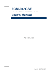
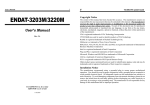
NEXCOM International Co., Ltd. Industrial Computing Solutions Multi-media Panel PC MPPC 2210/T User Manual NEXCOM International Co., Ltd. Published October 2009 www.nexcom.com Contents Contents Preface Chapter 4: Award BIOS Setup Copyright .............................................................................................. iii Disclaimer .............................................................................................. iii Acknowledgements ............................................................................... iii Regulatory Compliance Statements . ...................................................... iii Federal Communications Commission (FCC) For Class A Device.............. iii CE Certification ..................................................................................... iv Starting Setup . .....................................................................................11 Using Setup ..........................................................................................11 Getting Help .........................................................................................13 In Case of Problems ..............................................................................13 Main Menu . .........................................................................................13 Standard CMOS Features ......................................................................14 Advanced BIOS Features .......................................................................15 Advanced Chipset Features ...................................................................18 Integrated Peripherals ...........................................................................20 Power Management Setup ...................................................................24 PnP/PCI Configurations .........................................................................26 PC Health Status ...................................................................................27 Load Optimized Defaults . .....................................................................28 Save & Exit Setup ..................................................................................29 Chapter 1: General Information Main Feature...........................................................................................1 Specifications . ........................................................................................1 System Overview ....................................................................................2 System Dimension ..................................................................................3 Chapter 2: Jumper Setting Before You Begin ....................................................................................4 Precautions .............................................................................................4 Installation Procedure . ............................................................................5 Main Memory .........................................................................................5 Jumper and Connector List .....................................................................6 Chapter 3: Hardware Configuration Installing Memory ...................................................................................9 Installing HDD . .......................................................................................9 Copyright © 2009 NEXCOM International Co., Ltd. All Rights Reserved. ii MPPC 2210/T User Manual Preface Preface Copyright Acknowledgements This publication, including all photographs, illustrations and software, is protected under international copyright laws, with all rights reserved. No part of this manual maybe reproduced, copied, translated or transmitted in any form or by any means without the prior written consent from NEXCOM International Co., Ltd. The MPPC series is a trademark of NEXCOM international CO., LTD. All other product names mentioned herein are registered trademarks of their respective owners. Regulatory Compliance Statements Version 1.2 This section provides the FCC compliance statement for Class A devices and describes how to keep the system CE compliant. Copyright 2005 Disclaimer Federal Communications Commission (FCC) For Class A Device The information in this document is subject to change without prior notice and does not represent commitment from NEXCOM International Co., LTD. However, users may update their knowledge of any product in use by constantly checking its manual posted on our website: http://www.nexcom. com. NEXCOM shall not be liable for direct, indirect, special, incidental, or consequential damages arising out of the use of any product, nor for any infringements upon the rights of third parties, which may result from such use. Any implied warranties of merchantability of fitness for any particular purpose is also disclaimed. Copyright © 2009 NEXCOM International Co., Ltd. All Rights Reserved. This equipment has been tested and verified to comply with the limits for a Class A digital device, pursuant to Part 15 of FCC Rules. These limits are designed to provide reasonable protection against harmful interference when the equipment is operated in a commercial environment. This equipment generates, uses, and can radiate radio frequency energy and, if not installed and used in accordance with the instructions, may cause harmful interference to radio communications. Operation of this equipment in a residential area (domestic environment) is likely to cause harmful interference, in which case the user will be required to correct the interference (take adequate measures) at their own expense. iii MPPC 0810/T User Manual Preface CE Certification Safety Information The product(s) described in this manual complies with all applicable European Union (CE) directives if it has a CE marking. For computer systems to remain CE compliant, only CE-compliant parts may be used. Maintaining CE compliance also requires proper cable and cabling techniques. Before installing and using the MPPC series, note the following precautions: ▪▪ Read all instructions carefully. ▪▪ Do not place the unit on an unstable surface, cart, or stand. ▪▪ Follow all warnings and cautions in this manual. ▪▪ When replacing parts, ensure that your service technician Warnings specified by the manufacturer. uses parts ▪▪ Avoid using the system near water, in direct sunlight, or near a hearing Read and adhere to all warnings, cautions, and notices in this guide and the documentation supplied with the chassis, power supply, and accessory modules. If the instructions for the chassis and power supply are inconsistent with these instructions or the instructions for accessory modules, contact the supplier to find out how you can ensure that your computer meets safety and regulatory requirements. device. Cautions Electrostatic discharge (ESD) can damage embedded computer components. Do the described procedures only at an ESD workstation. If no such station is available, you can provide some ESD protection by wearing an antistatic wrist strap and attaching it to a metal part of the computer chassis. Copyright © 2009 NEXCOM International Co., Ltd. All Rights Reserved. iv MPPC 0810/T User Manual Chapter 1: General Information Chapter 1: General Information ▪▪ Luminance: 300 cd/m² ▪▪ Contrast ratio: 1000 ▪▪ Viewing angle: 80(U), 80(D), 85(L), 85(R ) ▪▪ Response time: 5 ms ▪▪ Backlight: CCFL ▪▪ Touch screen(optional): 5-line Resistive ▪▪ Touch Light Transmission: 80% ▪▪ Touch Interface: USB Main Feature Multimedia Panel PC ▪▪ 16:9 21.6” Fan-less panel Computer ▪▪ Intel® Atom™ N270, Low Consumption CPU ▪▪ VGA ▪▪ Dual GbE ▪▪ USB x 2/1 x Mini-PCIe/1 x CF/1 x RS232/422/485 ▪▪ Optional Touch screen, WiFi Module, 2.5”HDD ▪▪ DDR2 1GB (onboard 1G for 5.25”) ▪▪ 2.5” HDD bracket. ▪▪ Two speakers ▪▪ CF as default(DVI/COM2/TV-out as optional) ▪▪ +12V Power Adaptor ▪▪ Dimension: 508(W)x301(H)x53.9(D)mm 1.2 Specifications System ▪▪ CPU: Onboard Intel® Atom™ N270 1.6GHz(2.5W) ▪▪ BIOS: Award 8Mbit Flash BIOS ▪▪ System Chipset: Intel® 945GSE / ICH7M ▪▪ I/O Chip: ITE8712F ▪▪ System Memory: Onboard 1GB DDR2 and One 200-pin DDR2 SODIMM supports up to 2GB DDR2 400/533 (1GB per bank) ▪▪ SSD: One CF socket by IDE secondary slave channel supports Type I / II Compact Flash Card Specifications ▪▪ Hard Driver Bay: Optional 2.5” SATA HDD ▪▪ Watchdog Timer: Reset: 1 sec.~255 min. and 1 sec. or 1 min./step ▪▪ H/W Status Monitor: Monitoring system temperature, voltage, and Panel ▪▪ LCD size: 21.6”, 16:9 ▪▪ Resolution: Full HD, 1920x1080 cooling fan status. Auto throttling control when CPU overheats ▪▪ Pixel pitch: 0.248mm(H) x 0.248mm(V) Copyright © 2009 NEXCOM International Co., Ltd. All Rights Reserved. ▪▪ Expansion: Mini-PCI, Mini-PCIe 1 MPPC 2210/T User Manual Chapter 1: General Information Rear I/O ▪ Serial Port: 1 x RS232/422/485 ▪ Ethernet: 2 x RJ45 ▪ ▪ ▪ Order Information ▪ MPPC 2210: 21.6” TFT Panel PC with Intel® Atom™ N270 1.6 GHz ▪ MPPC 2210T: 21.6” TFT Panel PC with Intel® Atom™ N270 1.6 GHz with Touch screen VGA: 1 x DB-15 Audio port: Line out System Overview USB: 2 x USB 2.0 Audio ▪ AC97 Codec: Realtek ALC 655 supports 5.1CH Audio ▪ Audio Interface: Connector: Line out Ethernet ▪ LAN Chip: Dual Realtek RTL8111C Gigabit LAN ▪ Ethernet Interface: 10/100/1000 Base-Tx Fast Ethernet compatible Mechanical & Environment ▪ Color: Front & Rear panel Black ▪ Mounting: Wall/Stand/VESA 75 mm x 75 mm or 100mm x100mm ▪ ▪ ▪ ▪ ▪ ▪ ▪ ▪ Vibration: Operating test: EC 60068-2-64 Non-operating test: IEC60068-2-6 Power Input: 100~250 Vdc/ 47~63 Hz Power Output: ‘+12 Vdc / 7A (80W) Operating Temperature: 32 to 104°F (0 to 40°C) Storage Temperature: -4 to 167°F (-20 to 75°C) Operating Humidity: 5%~90% relative humidity, non-condensing Dimensions: 508(W) x 301(H) x 53.9(D)mm Weight: 6 Kgs Copyright © 2009 NEXCOM International Co., Ltd. All Rights Reserved. 2 MPPC 2210/T User Manual Chapter 1: General Information System Dimension Copyright © 2009 NEXCOM International Co., Ltd. All Rights Reserved. 3 MPPC 2210/T User Manual Chapter 2: Jumper Setting Chapter 2: Jumper Setting This chapter of the User’s Manual describes how to set jumpers. Note: The procedures that follow are generic for all MPPC series. environments. A grounding strap is warranted whenever danger of static electricity exists. Before You Begin Precautions Ensure you have a stable, clean working environment. Dust and dirt can get into components and cause a malfunction. Use containers to keep small components separated. Computer components and electronic circuit boards can be damaged by discharges of static electricity. Working on the computers that are still connected to a power supply can be extremely dangerous. Follow the guidelines below to avoid damage to your computer or yourself: ▪▪ AAlways disconnect the unit from the power outlet whenever you are working inside the case. ▪▪ If possible, wear a grounded wrist strap when you are working inside the computer case. Alternatively, discharge any static electricity by touching the bare metal chassis of the unit case, or the bare metal body of any other grounded appliance. ▪▪ Hold electronic circuit boards by the edges only. Do not touch the components on the board unless it is necessary to do so. Don’t flex or stress the circuit board. ▪▪ Leave all components inside the static-proof packaging that they shipped with until they are ready for installation. ▪▪ Use correct screws and do not over tighten screws. Adequate lighting and proper tools can prevent you from accidentally damaging the internal components. Most of the procedures that follow require only a few simple tools, including the following: ▪▪ A Philips screwdriver ▪▪ A flat-tipped screwdriver ▪▪ A set of jewelers Screwdrivers ▪▪ A grounding strap ▪▪ An anti-static pad Using your fingers can disconnect most of the connections. It is recommended that you do not use needle-nosed pliers to disconnect connections as these can damage the soft metal or plastic parts of the connectors. Before working on internal components, make sure that the power is off. Ground yourself before touching any internal components, by touching a metal object. Static electricity can damage many of the electronic components. Humid environment tend to have less static electricity than dry Copyright © 2009 NEXCOM International Co., Ltd. All Rights Reserved. 4 MPPC 2210/T User Manual Chapter 2: Jumper Setting Installation Procedure Main Memory This chapter explains you the instructions of how to setup your system. MPPC2210/T provides one 200-pin SODIMM sockets to support DDR2 SDRAM. The total maximum memory size is 2GB. 1. Turn off the power supply. 2. Insert the SODIMM module (be careful with the orientation). 3. Insert all external cables for hard disk, floppy, keyboard, mouse, USB etc. except for flat panel. A CRT monitor must be connected in order to change CMOS settings to support flat panel. SODIMM 4. Connect power adaptor supply to MPPC 5. Turn on the power. 6. Enter the BIOS setup by pressing the delete key during boot up. Use the “LOAD BIOS DEFAULTS” feature. The Integrated Peripheral Setup and the Standard CMOS Setup Window must be entered and configured correctly to match the particular system configuration. 7. If TFT panel display is to be utilized, make sure the panel voltage is correctly set before connecting the display cable and turning on the power. Make sure to unplug the power supply before adding or removing SODIMMs or other system components. Failure to do so may cause severe damage to both the board and the components. Copyright © 2009 NEXCOM International Co., Ltd. All Rights Reserved. 5 MPPC 2210/T User Manual Chapter 2: Jumper Setting ▪ ▪ ▪ ▪ Jumper and Connector List Locate the SODIMM socket on the board. Hold two edges of the SODIMM module carefully. Keep away of touching its connectors. Align the notch key on the module with the rib on the slot. You can configure your board to match the needs of your application by setting jumpers. A jumper is the simplest kind of electric switch. It consists of two metal pins and a small metal clip (often protected by a plastic cover) that slides over the pins to connect them. To “close” a jumper you connect the pins with the clip. To “open” a jumper you remove the clip. Sometimes a jumper will have three pins, labeled 1, 2, and 3. In this case, you would connect either two pins. Firmly press the modules into the socket automatically snaps into the mounting notch. Do not force the SODIMM module in with extra force as the SODIMM module only fit in one direction. Mounting Notch Notch Key Ejector Tab Ejector Tab The jumper settings are schematically depicted in this manual as follows: 200-pin DDRSODIMM ▪ To remove the SODIMM modules, push the two ejector tabs on the slot outward simultaneously, and then pull out the SODIMM module. A pair of needle-nose pliers may be helpful when working with jumpers. Note: (1) Please do not change any DDR2 SDRAM parameter in BIOS setup to increase your system’s performance without acquiring technical information in advance. Connectors on the board are linked to external devices such as hard disk drives, a keyboard, or floppy drives. In addition, the board has a number of jumpers that allow you to configure your system to suit your application. (2) Static electricity can damage the electronic components of the computer or optional boards. Before starting these procedures, ensure that you are discharged of static electricity by touching a grounded metal object briefly. If you have any doubts about the best hardware configuration for your application, contact your local distributor or sales representative before you make any changes. Copyright © 2009 NEXCOM International Co., Ltd. All Rights Reserved. 6 MPPC 2210/T User Manual Chapter 2: Jumper Setting Clear CMOS (JCMOS1) The following tables list the function of each of the board’s jumpers and connectors. Jumpers Label JCMOS1 JIDEMS Function Clear CMOS CF Master/Slave Select Note 3 x 1 header, pitch 2.0mm 3 x 1 header, pitch 2.0mm Function Compact Flash card connector Serial Port 1 connector 200-pin DDR2 SODIMM socket General purpose I/O connector Primary IDE connector PS/2 keyboard & mouse connector RJ-45 Ethernet 1 RJ-45 Ethernet 2 Mini-PCI connector SATA1 power input Power connector Power connector Serial ATA connector 1&2 USB connector USB connector USB connector VGA connector LCD backlight brightness adjustment TV-out connector Reset/Power bottom Note Protect* Connectors Label JCF1 JCOM1 JDIMM1 JDIO1 JIDE1 JKBMS2 JLAN1 JLAN2 JMPCI1 JPSATA1 JPWR1 JPWR2 JSATA1&2 JUSB1 JUSB2 JUSB3 JVGA1 JVR1 JTV1 S1 3 10 x 2 header, pitch 2.0mm 22 x 2 header, pitch 2.0mm 4 x 2 header, pitch 2.54mm 1 Clear CMOS 3 1 * Default 2 x 1 wafer, pitch 2.54mm 2 x 2 wafer, pitch 4.2mm CF Master/Slave select (JIDEMS) Wafer 7P pitch 1.27mm 5 x 2 header, pitch 2.0mm 5 x 2 header, pitch 2.0mm Master* 3 x 2 header, pitch 2.0mm 3 x 2 header, pitch 2.0mm 3 1 Slave 3 1 * Default Copyright © 2009 NEXCOM International Co., Ltd. All Rights Reserved. 7 MPPC 2210/T User Manual Chapter 2: Jumper Setting General purpose I/O connector (JDIO1) IDE Connector (JIDE1) 19 43 1 1 Signal PIN PIN Signal Signal PIN PIN Signal Signal PIN PIN Signal Signal PIN PIN Signal +5V 20 19 GND GPIO34 10 9 GPIO24 RESET# 1 2 GND PDIOW# 23 24 GND SMB_DATA 18 17 SMB_CLK GPIO33 8 7 GPIO23 PDD7 3 4 PDD8 PDIOR# 25 26 GND GPIO37 16 15 GPIO27 GPIO32 6 5 GPIO22 PDD6 5 6 PDD9 PIORDY 27 28 CSEL GPIO36 14 13 GPIO26 GPIO31 4 3 GPIO21 PDD5 7 8 PDD10 PDACK# 29 30 GND GPIO35 12 11 GPIO25 GPIO30 2 1 GPIO20 PDD4 9 10 PDD11 IRQ15 31 32 NC PDD3 11 12 PDD12 PDA1 33 34 LID PDD2 13 14 PDD13 PDA0 35 36 PDA2 PDD1 15 16 PDD14 PDCS1# 37 38 PDCS3# PDD0 17 18 PDD15 HD_LED1 39 40 GND GND 19 20 NC +5V 41 42 +5V PDREQ 21 22 GND GND 43 44 NC Copyright © 2009 NEXCOM International Co., Ltd. All Rights Reserved. 8 MPPC 2210/T User Manual Chapter 3: Hardware Configuration Chapter 3: Hardware Configuration Installing Memory Installing HDD Step 1. Unfasten 6 screws from the case. Then take off the top chassis. Step 1. Unfasten 2 screws of the bracket and take it off. Step 2. Insert the SODIMM into the memory socket. Step 2. Insert the HDD into the bracket and fasten 4 screws. Copyright © 2009 NEXCOM International Co., Ltd. All Rights Reserved. 9 MPPC 2210/T User Manual Chapter 3: Hardware Configuration Step 3. Unlock 2 screws from the rear side of the panel PC as above. Step 5. Insert the HDD back and fasten 2 screws. HDD Step 6. Place back the chassis with 6 screws locked. Step 4. By default, the SATA cables had been inserted to the according connectors. Just connect to SATA HDD with the two cables. SATA cable SATA wire Copyright © 2009 NEXCOM International Co., Ltd. All Rights Reserved. 10 MPPC 2210/T User Manual Chapter 4: BIOS Setup Chapter 4: BIOS Setup This chapter explains how to use the BIOS Setup program for the MPPC2210/T. The current BIOS setup pictures in the chapter are for reference only, which may change by the BIOS modification in the future. User can download any major updated items or reversion from NEXCOM web site http://www. nexcom.com.tw. If any unclear message occurs, please contact NEXCOM customer service representative for help or log onto If the message disappears before you respond and you still wish to enter Setup, restart the system to try again by turning it OFF then ON or pressing the “RESET” button on the system case. You may also restart by simultaneously pressing <Ctrl>, <Alt>, and <Delete> keys. If you do not press the keys at the correct time and the system does not boot, an error message will be displayed and you will again be asked to. http://www.nexcom.com.tw/contact/contact.htm. Press to Continue, to enter SETUP Starting Setup The AwardBIOS™ is immediately activated when you first power on the computer. The BIOS reads the system information contained in the CMOS and begins the process of checking out the system and configuring it. When it finishes, the BIOS will seek an operating system on one of the disks and then launch and turn control over to the operating system. Using Setup In general, you use the arrow keys to highlight items, press <Enter> to select, use the PageUp and PageDown keys to change entries, press <F1> for help and press <Esc> to quit. The following table provides more detail about how to navigate in the Setup program using the keyboard. While the BIOS is in control, the Setup program can be activated in one of two ways: By pressing <Del> immediately after switching the system on, or By pressing the <Del> key when the following message appears briefly at the bottom of the screen during the POST (Power On Self Test). Press to enter SETUP Copyright © 2009 NEXCOM International Co., Ltd. All Rights Reserved. 11 MPPC 2210/T User Manual Chapter 4: BIOS Setup Button Description Button Description Move to previous item Reserved Move to next item Restore the previous CMOS value from CMOS, only for Option Page Setup Menu Move to the item in the left hand Load the default CMOS value from BIOS default table, only for Option Page Setup Menu Move to the item in the right hand Load the default Main Menu -- Quit and not save changes into CMOS Reserved Status Page Setup Menu and Option Page Setup Menu -- Exit current page and return to Main Menu Reserved Increase the numeric value or make changes Save all the CMOS changes, only for Main Menu Decrease the numeric value or make changes ▪▪ Navigating Through The Menu Bar Increase the numeric value or make changes Use the left and right arrow keys to choose the menu you want to be in. Decrease the numeric value or make changes Note: Some of the navigation keys differ from one screen to another. General help, only for Status Page Setup Menu and Option Page Setup Menu ▪▪ To Display a Sub Menu Change color from total 16 colors. F2 to select color forward, (Shift) F2 to select color backward Use the arrow keys to move the cursor to the sub menu you want. Then press <Enter>. A “” pointer marks all sub menus. Calendar, only for Status Page Setup Menu Copyright © 2009 NEXCOM International Co., Ltd. All Rights Reserved. 12 MPPC 2210/T User Manual Chapter 4: BIOS Setup Getting Help Main Menu Press F1 to pop up a small help window that describes the appropriate keys to use and the possible selections for the highlighted item. To exit the Help Window press <Esc> or the F1 key again. Once you enter the AwardBIOS™ CMOS Setup Utility, the Main Menu will appear on the screen. The Main Menu allows you to select from several setup functions and two exit choices. Use the arrow keys to select among the items and press <Enter> to accept and enter the sub-menu. In Case of Problems Note that a brief description of each highlighted selection appears at the bottom of the screen. If, after making and saving system changes with Setup, you discover that your computer no longer is able to boot, the AwardBIOS™ supports an override to the CMOS settings which resets your system to its defaults. The best advice is to only alter settings which you thoroughly understand. To this end, we strongly recommend that you avoid making any changes to the chipset defaults. These defaults have been carefully chosen by both Award and your systems manufacturer to provide the absolute maximum performance and reliability. Even a seemingly small change to the chipset setup has the potential for causing you to use the override. Note: The BIOS setup screens shown in this chapter are for reference purposes only, and may not exactly match what you see on your screen. Visit the Avalue website (www.avalue.com.tw) to download the latest product and BIOS information. Copyright © 2009 NEXCOM International Co., Ltd. All Rights Reserved. 13 MPPC 2210/T User Manual Chapter 4: BIOS Setup Standard CMOS Features The items in Standard CMOS Setup Menu are divided into few categories. Each category includes no, one or more than one setup items. Use the arrow keys to highlight the item and then use the <PgUp> or <PgDn> keys to select the value you want in each item. Item Options Description Time HH : MM : SS Set the system time IDE Channel 0 Master IDE Channel 0 Slave IDE Channel 1 Master IDE Channel 1 Slave Options are in 3.5.1.2 Press <Enter> to enter the sub menu of detailed options Video Halt On EGA/VGA CGA 40 CGA 80 MONO All Errors No Errors All, but Keyboard Select the default video device Select the situation in which you want the BIOS to stop the POST process and notify you IDE Adapter Setup The IDE adapters control the hard disk drive. Use a separate sub menu to configure each hard disk drive. The below table will shows the IDE primary master sub menu. Item Options Description IDE HDD Auto-detection Press Enter Press Enter to auto-detect the HDD on this channel. If detection is successful, it fills the remaining fields on this menu. IDE Channel 0 Master None IDE Channel 0 Slave Auto IDE Channel 1 Master Manual IDE Channel 1 Slave Access Mode Choose the access mode for this hard disk The following options are selectable only if the ‘IDE Channel …’ item is set to ‘Manual’ Main Menu Selection Cylinder This reference table shows the selections that you may make on the Main Menu. Head Precomp Landing zone Sector Copyright © 2009 NEXCOM International Co., Ltd. All Rights Reserved. CHS, LBA Large, Auto Selecting ‘manual’ lets you set the remaining fields on this screen. Selects the type of fixed disk. “User Type” will let you select the number of cylinders, heads, etc. Note: PRECOMP=65535 means NONE ! 14 Min = 0 Max = 65535 Min = 0 Max = 255 Min = 0 Max = 65535 Min = 0 Max = 65535 Min = 0 Max = 255 Set the number of cylinders for this hard disk. Set the number of read/write heads **** Warning: Setting a value of 65535 means no hard disk **** Number of sectors per track MPPC 2210/T User Manual Chapter 4: BIOS Setup Advanced BIOS Features CPU Feature This section allows you to configure your system for basic operation. You have the opportunity to select the system’s default speed, boot-up sequence, keyboard operation, shadowing and security. Item Options Description Delay Prior to Thermal 4, 8, 16, 32 Min Allow the Thermal Monitor to be activated of certain minutes in automatic mode after the system boots. Thermal Management Thermal Monitor 1 Allow to choose the thermal management method of Thermal Monitor 2 the monitor. TM2 Bus Ratio 0~255 Represents the frequency. Bus ratio of the throttled performance state that will be initiated when the ondie sensor goes from not hot to hot. TM2 Bus VID 0.700 ~ 1.708 Represents the voltage of the throttled performance state that will be initiated when the on-die sensor goes from not hot to hot. This item allows you to setup the CPU thermal management function. Limit CPUID MaxVal Disable Enable C1E Function Auto, Disabled The C1E function enables the Core™ 2 Extreme to throttle back to its standard clock rate under light load Execute Disable Bit Enabled, Disabled It can help prevent certain classes of malicious buffer overflow attacks when combined with a supporting operating system. Virtualization Technology Enabled, Disabled Copyright © 2009 NEXCOM International Co., Ltd. All Rights Reserved. 15 In order to mask the physical CPUID for Proscott core when running WinNT, Award BIOS provides “Limit CPUID MaxVal” feature. Enabling this feature will make the main board BIOS respond “suitable”, “virtual” CPUID to OS kernel. So WinNT or the legacy OS can use the masked CPUID to work well with the new CPU design. This BIOS feature is used to enable or disable the Intel® Virtualization Technology (IVT) extensions that allow multiple operating systems to run simultaneously on the same system. MPPC 2210/T User Manual Chapter 4: BIOS Setup Hard Disk Boot Priority Virus Warning Allows you to choose the VIRUS Warning feature for IDE Hard Disk boot sector protection. If this function is enabled and someone attempt to write data into this area, BIOS will show a warning message on screen and alarm beep. Item Description Enabled Activates automatically when the system boots up causing a warning message to appear when anything attempts to access the boot sector or hard disk partition table. Disabled No warning message will appear when anything attempts to access the boot sector or hard disk partition table. CPU L1 & L2 & L3 Cache The item allows you to speed up memory access. However, it depends on CPU design. This item allows you to set the boot priority of the hard drives installed in the system. Item Description Pri./Sec. Master/Slave Boot up from IDE Primary/Secondary Master/Slave Hard Disk USBHDD 0/1/2 Boot up from 1st/2nd/3rd USB Hard Disk Bootable Add-in Cards Boot up from other Add-In Card Hard Disk Device. Copyright © 2009 NEXCOM International Co., Ltd. All Rights Reserved. Item Description Enabled Enable cache Disabled Disable cache Hyper-Threading Technology The item allows you to enable HT Technology. However, it depends on CPU design. 16 Item Description Enabled Enable cache Disabled Disable cache MPPC 2210/T User Manual Chapter 4: BIOS Setup Quick Power On Self Test Typematic Rate Setting This category speeds up Power On Self Test (POST) after you power up the computer. If it is set to Enable, BIOS will shorten or skip some check items during POST. This feature enables you to control the keystroke repeat rate when you depress a key continuously. When enabled, you can manually adjust the settings using the two typematic controls (Typematic Rate and Typematic Delay). If disabled, the BIOS will use the default setting. Item Description Enabled Enable quick POST Item Description Disabled Normal POST Enabled Enable typematic rate/delay setting Disabled Disable typematic rate/delay setting First/Second/Third/Other Boot Device Security Option The BIOS attempts to load the operating system from the devices in the sequence selected in these items. Select whether the password is required every time the system boots or only when you enter setup. Item Description LS120 LS120 Device Hard Disk Hard Disk Device CDROM CDROM Device ZIP100 ZIP-100 Device USB-FDD USB Floppy Device USB-ZIP USB ZIP Device USB-CDROM USB CDROM Device Note: LAN Network Device Disabled Disabled any boot device To disable security, select PASSWORD SETTING at Main Menu and then you will be asked to enter password. Do not type anything and just press <Enter>, it will disable security. Once the security is disabled, the system will boot and you can enter Setup freely. Item Description System The system will not boot and access to Setup will be denied if the correct password is not entered at the prompt. Setup The system will boot, but access to Setup will be denied if the correct password is not entered at the prompt. Boot Up NumLock Status Select power on state for NumLock. APIC Mode Item Description On Enable NumLock The BIOS supports versions 1.4 of the Intel® multiprocessor specification. When enabled, The MPS Version 1.4 Control for OS can be activated. Off Disable NumLock Copyright © 2009 NEXCOM International Co., Ltd. All Rights Reserved. The choice: Enabled/Disabled. 17 MPPC 2210/T User Manual Chapter 4: BIOS Setup Advanced Chipset Features MPS Version Control For OS This feature is only applicable to multiprocessor board as it specifies the version of the Multi-Processor Specification (MPS) that the board will use. This section allows you to configure the system based on the specific features of the installed chipset. This chipset manages bus speeds and access to system memory resources, such as DRAM and the external cache. It also coordinates communications between the conventional ISA bus and the PCI bus. It must be stated that these items should never need to be altered. The default settings have been chosen because they provide the best operating conditions for your system. The only time you might consider making any changes would be if you discovered that data was being lost while using your system. The choice: 1.4, 1.1. OS Select for DRAM > 64MB Select the operating system that is running with greater than 64MB of RAM on the system. Item Description Non-OS2 Disable OS for over 64 MB DRAM OS2 Enable OS for over 64 MB DRAM The first chipset settings deal with CPU access to dynamic random access memory (DRAM). The default timings have been carefully chosen and should only be altered if data is being lost. Such a scenario might well occur if your system had mixed speed DRAM chips installed so that greater delays may be required to preserve the integrity of the data held in the slower memory chips. Report No FDD For WIN95 The original Windows95 requires the presence of a floppy. Unless the BIOS tells it to disregard the absence of the drive, it will generate an error message. For other operating systems as Win98 etc this field is without relevance. Item Description No Don’t generate error message Yes Generate error message Small Logo (EPA) Show This item allows you enabled/disabled the small EPA logo show on screen at the POST step. Item Description Enabled EPA Logo show is enabled Disabled EPA Logo show is disabled Copyright © 2009 NEXCOM International Co., Ltd. All Rights Reserved. 18 MPPC 2210/T User Manual Chapter 4: BIOS Setup Onboard – DRAM DRAM RAS# Precharge This item allows you to select the onboard – DRAM by yourself. This option sets the number of cycles required for the RAS to accumulate its charge before the SDRAM refreshes. Reducing the precharge time to 2 improves SDRAM performance but if the precharge time of 2 is insufficient for the installed SDRAM, the SDRAM may not be refreshed properly and it may fail to retain data The choices: Enabled, Disabled. DRAM Timing Selectable This item allows you to select the DRAM timing value by SPD data or Manual by yourself. So, for better SDRAM performance, set the SDRAM RAS Precharge Time to 2 but increase it to 3 if you face system stability issues after reducing the precharge time. The choices: Manual, By SPD. The choices: 2, 3, 4, 5, 6, Auto. CAS Latency Tim Precharge Delay (tRAS) This item controls the time delay (in clock cycles - CLKs) that passes before the SDRAM starts to carry out a read command after receiving it. This also determines the number of CLKs for the completion of the first part of a burst transfer. In other words, the lower the latency, the faster the transaction. It allows controlling the memory bank’s minimum row active time (tRAS). This constitutes the time when a row is activated until the time the same row can be deactivated. If the tRAS period is too long, it can reduce performance by unnecessarily delaying the deactivation of active rows. Reducing the tRAS period allows the active row to be deactivated earlier. The choices: 5, 4, 3, 6, Auto. If the tRAS period is too short, there may not be enough time to complete a burst transfer. This reduces performance and data may be lost or corrupted. DRAM RAS# to CAS# Delay This option allows you to insert a delay between the RAS (Row Address Strobe) and CAS (Column Address Strobe) signals. This delay occurs when the SDRAM is written to, read from or refreshed. Naturally, reducing the delay improves the performance of the SDRAM while increasing it reduces performance. The choices: Auto, 4, 5, 6, 7, 8, 9, 10, 11, 12, 13, 14, 15. System Memory Frequency The choices: 2, 3, 4, 5, 6, Auto. It allows controlling the system memory frequency. The memory frequency will either be equal to or less than the processor system bus frequency. The choices: Auto, 400MHz, 533MHz. Copyright © 2009 NEXCOM International Co., Ltd. All Rights Reserved. 19 MPPC 2210/T User Manual Chapter 4: BIOS Setup Integrated Peripherals System BIOS Cacheable This feature is only valid when the system BIOS is shadowed. It enables or disables the caching of the system BIOS ROM at F0000h-FFFFFh via the L2 cache. This greatly speeds up accesses to the system BIOS. However, this does not translate into better system performance because the OS does not need to access the system BIOS much. Use this menu to specify your settings for integrated peripherals. The choices: Disabled, Enabled. Video BIOS Cacheable This feature is only valid when the video BIOS is shadowed. It enables or disables the caching of the video BIOS ROM at C0000h-C7FFFh via the L2 cache. This greatly speeds up accesses to the video BIOS. However, this does not translate into better system performance because the OS bypasses the BIOS using the graphics driver to access the video card’s hardware directly. The Choice: Enabled, Disabled. Memory Hole At 15M-16M Enabling this feature reserves 15MB to 16MB memory address space to ISA expansion cards that specifically require this setting. This makes the memory from 15MB and up unavailable to the system. Expansion cards can only access memory up to 16MB. The choice: Enable, Disable. Copyright © 2009 NEXCOM International Co., Ltd. All Rights Reserved. 20 MPPC 2210/T User Manual Chapter 4: BIOS Setup OnChip IDE Device The chipset contains a PCI IDE interface with support for one IDE channel and two SATA channels. Select Enabled to activate the primary IDE interface. Select Disabled to deactivate this interface. Item Options Description Enabled Disabled Speeds up HDD access by transferring data from multiple sectors at once instead of using the old single sector transfer mode if the HDD supports block transfers and configure the proper block transfer settings for it. Up to 64KB of data can be transferred per interrupt with IDE HDD Block Mode enabled. (Virtually all HDDs now support block transfers.) IDE DMA transfer access Enabled Disabled It allows you to enable or disable DMA (Direct Memory Access) support for all IDE devices. If you disable this BIOS feature, the BIOS will disable DMA transfers for all IDE drives. They will revert to PIO mode transfers. If you enable this BIOS feature, the BIOS will enable DMA transfers for all IDE drives. The proper DMA mode will be detected at boot-up. If the drive does not support DMA transfers, then it will use PIO mode instead. On-Chip Primary/ Secondary PCI IDE Enabled Disabled The integrated peripheral controller contains an IDE interface with support for two IDE channels. It allows you to activate each channel separately. IDE Primary Master PIO IDE Primary Slave PIO IDE Secondary Master PIO IDE Secondary Slave PIO Auto Mode 0 Mode 1 Mode 2 Mode 3 Mode 4 The IDE PIO (Programmed Input/Output) fields let you set a PIO mode (0-4) for each of the four IDE devices that the onboard IDE interface supports. Modes 0 through 4 provide successively increased performance. In Auto mode, the system automatically determines the best mode for each device. Auto Disabled Ultra DMA implementation is possible only if your IDE hard drive supports it and the operating environment includes a DMA driver (Windows 95 OSR2 or a thirdparty IDE bus master driver). If the hard drive and the system software both support Ultra DMA, select Auto to enable BIOS support. IDE HDD Block Mode IDE Primary Master UDMA IDE Primary Slave UDMA IDE Secondary Master UDMA IDE Secondary Slave UDMA Copyright © 2009 NEXCOM International Co., Ltd. All Rights Reserved. 21 MPPC 2210/T User Manual Chapter 4: BIOS Setup On-Chip Serial ATA Setting The field under the SATA setting includes SATA Mode (IDE), On-Chip Serial ATA (Auto), PATA IDE Mode (Secondary) and SATA Port (P0, P2 is Primary). Item Options Description SATA Mode IDE AHCI It allows you to select the operation mode for SATA controller. On-Chip Serial ATA Disabled, Auto, Combined Mode, It provides access to set the mode of the On-Chip Enhanced Mode, SATA devices. SATA Only Disabled SATA PORT Speed Settings Force GEN I Force GEN II This item allows you to select the speed of SATA ports. PATA IDE Mode This item shows the PATA IDE mode. Secondary Item Options Description Azalia/AC97 Audio Select Auto Azalia AC97 Audio All Disabled This item allows you to select the Audio codec. Onboard LAN1 Device Enabled Disabled This item allows you to enabled the PCIe Lan1 Device. Onboard LAN2 Device Enabled Disabled This item allows you to enabled the PCIe Lan2 Device Onboard Lan Boot ROM Enabled Disabled This item allows you to enabled the LAN Boot ROM. Super IO Device Onboard Device Copyright © 2009 NEXCOM International Co., Ltd. All Rights Reserved. 22 MPPC 2210/T User Manual Chapter 4: BIOS Setup Item Options Description Onboard Serial Port 1 Onboard Serial Port 2 Disabled, 3F8/IRQ4 2F8/IRQ3, 3E8/IRQ4 2E8/IRQ3, Auto Select an address and corresponding interrupt for the first and second serial ports. COM1 232/422/485 COM2 232/422/485 RS232 RS422 RS485 It allows you to select the COM Port mode Onboard Parallel Port Disabled, 378/IRQ7 278/IRQ5, 3BC/IRQ7 Select a matching address and interrupt for the physical parallel (printer) port. USB Device Setting PWRON After PWR-Fail This option will determine PWRON after PWR-Fail. The choices: Off, On, Former-Sts Watch Dog Timer This option will determine watch dog timer. The choices: Disabled, 30,40,50,60 Sec, 2, 10, 30 Min. Copyright © 2009 NEXCOM International Co., Ltd. All Rights Reserved. 23 Item Options Description USB 1.0 Controller Disabled Enabled This item enables you to use the onboard USB 1.0 controller to communicate with your USB devices USB 2.0 Controller Enabled Disabled This item enables you to use the onboard USB 2.0 controller to communicate with your USB devices USB Operation Mode Full/Low Speed This item allows you to select the USB mode. High Speed USB Keyboard Function Disabled Enabled This BIOS feature determines if support for the USB keyboard should be provided by the operating system or the BIOS. USB Mouse Function Enabled Disabled This BIOS feature determines if support for the USB mouse should be provided by the operating system or the BIOS. USB Storage Function Enabled Disabled This BIOS feature determines if support for the USB Storage should be provided by the operating system or the BIOS. MPPC 2210/T User Manual Chapter 4: BIOS Setup Power Management Setup ACPI Suspend Type The Power Management Setup allows you to configure you system to most effectively save energy while operating in a manner consistent with your own style of computer use. The choices: S1(POS), S3(STR).S1&S3. This item will set which ACPI suspend type will be used. Run VGABIOS if S3 Resume There are 3 modes for you to decide to operate VGABIOS or not when the ACPI suspend type is S3. The choices: Auto, Yes, No Power Management This category allows you to select the type (or degree) of power saving and is directly related to the following modes: Item User Defined Min. Saving PCI Express PM Function Description Allows you to set each mode individually. When not disabled, each of the ranges are from 1 min. to 1 hr. except for HDD Power Down which ranges from 1 min. to 15 min. and disable. Minimum power management, HDD Power Down = 15 Min, Max. Saving Maximum power management, HDD Power Down =1 Min, Disabled Power management is disabled. Video Off Method This item allows you to enable/disable the PCI Express PME Function. The choices: Enabled, Disabled. This determines the manner in which the monitor is blanked. The choices: Blank Screen, V/H SYNC+Blank, DPMS. ACPI Function Video Off In Suspend This item allows you to enable/disable the ACPI function. This determines the manner in which the monitor is blanked. The choices: Enabled, Disabled. The choice: No, Yes. Copyright © 2009 NEXCOM International Co., Ltd. All Rights Reserved. 24 MPPC 2210/T User Manual Chapter 4: BIOS Setup Suspend Type Power On By Ring This function allows to select Suspend type. This determines whether the system boot up if there’s an incoming call from the Modem. The choices: Stop Grant, PwrOn Suspend. The choices: Enable, Disabled. Suspended Mode Resume By Alarm It specifies the length of time of system inactivity while in full power on state before the computer enters suspend mode and motivates the enable ‘Wake Up Events In Doze & Standby’ / ‘PM Events’. This function is for setting date and time for your computer to boot up. The choices: Enabled, Disabled. The choices: Disabled, 1, 2, 4, 8, 12, 20, 30, 40 mins, 1 hr. Date<of Month>/Time<hh:mm:ss> Alarm HDD Power Down After enabled “Resume By Alarm”, set the specific date/hour/minute/second specified in these fields. When enable and after the set time of system inactivity, the hard disk drive will be powered down while all other devices remain active. The choices: Alarm Date: 01-31, Every Day / Alarm Hour: 00-23 / The choices: Disabled, 1 ~ 15 mins. Alarm Minute: 00-59/ Alarm Second: 00-59 Soft-Off by PWR-BTTN Primary/Secondary IDE 0/1, FDD,COM,LPT PORT, PCI PIRQ[A-D]# Pressing the power button for more than 4 seconds forces the system to enter the Soft-Off state when the system has “hung”.(Only could working on ATX Power supply) Reload Global Timer events are I/O events whose occurrence can prevent the system from entering a power saving mode or can awake the system from such a mode. In effect ,the system remain alert for anything which occurs to a device which is configured as Enabled ,even when the system is in a power down mode. The choices: Delay 4 Sec, Instant-Off. The choices: Enabled, Disabled. Wake Up by PCI Card This will enable the system to wake up through PCI Card peripheral. The choices: Enable, Disabled. Copyright © 2009 NEXCOM International Co., Ltd. All Rights Reserved. 25 MPPC 2210/T User Manual Chapter 4: BIOS Setup PnP/PCI Configuration Reset Configuration Data Normally, you leave this field Disabled. Select Enabled to reset Extended System Configuration Data (ESCD) when you exit Setup if you have installed a new add-on and the system reconfiguration has caused such a serious conflict that the operating system cannot boot. This section describes configuring the PCI bus system. PCI, or Personal Computer Interconnect, is a system which allows I/O devices to operate at speeds nearing the speed the CPU itself uses when communicating with its own special components. This section covers some very technical items and it is strongly recommended that only experienced users should make any changes to the default settings. The choices: Enabled, Disabled. Resources Controlled By The Award Plug and Play BIOS has the capacity to automatically configure all of the boot and Plug and Play compatible devices. However, this capability means absolutely nothing unless you are using a Plug and Play operating system such as Windows® 95. If you set this field to “manual” choose specific resources by going into each of the sub menu that follows this field (a sub menu is preceded by a “”). The choices: Auto(ESCD), Manual. PCI / VGA Palette Snoop Leave this field at Disabled. The choices: Enabled, Disabled. INT Pin 1/2/3/4/5/6/7/8 Assignment This feature allows you to assign the PCI IRQ numbers for PCI slots. Selecting the default, Auto, allows the PCI controller to automatically allocate the IRQ numbers. Init Display First It allows you to select whether to boot the system using the AGP graphics card or the PCI graphics card. This is particularly important if you have AGP and PCI graphics cards but only one monitor. The choices: Auto, 3, 4, 5, 7, 9, 10, 11, 12, 14, 15. The choices: PCI Slot, Onboard, PCIex. Copyright © 2009 NEXCOM International Co., Ltd. All Rights Reserved. 26 MPPC 2210/T User Manual Chapter 4: BIOS Setup Maximum Payload Size Load Fail-Safe Defaults This setting defines the maximum payload size. Use this menu to load the BIOS default values for the minimal/stable performance for your system to operate. The choices: 128, 256, 512, 1024, 2048, 4096. Press <Y> to load the BIOS default values for the most stable, minimalperformance system operations. PC Health Status This section shows the status of your CPU, Fan & System. Frequency/ Voltage Control Use this menu to specify your settings for frequency/voltage control. CPU Clock Ratio This feature allows owners to change the CPU Clock Ratio. The choices: 6~50 Copyright © 2009 NEXCOM International Co., Ltd. All Rights Reserved. 27 MPPC 2210/T User Manual Chapter 4: BIOS Setup Load Optimized Defaults Set Supervisor / User Password You can set either supervisor or user password, or both of them. Use this menu to load the BIOS default values that are factory settings for optimal performance system operations. While Award has designed the custom BIOS to maximize performance, the factory has the right to change these defaults to meet their needs. Supervisor Password: able to enter/change the options of setup menus. Press <Y> to load the default values setting for optimal performance system operations. Copyright © 2009 NEXCOM International Co., Ltd. All Rights Reserved. 28 MPPC 2210/T User Manual Chapter 4: BIOS Setup User Password: able to enter but no right to change the options of setup menus. every time your system is rebooted. This would prevent unauthorized use of your computer. You determine when the password is required within the BIOS Features Setup Menu and its Security option (see Section 3). If the Security option is set to “System”, the password will be required both at boot and at entry to Setup. If set to “Setup”, prompting only occurs when trying to enter Setup Save& Exit Setup Save CMOS value changes to CMOS and exit setup. Enter <Y> to store the selection made in the menus in CMOS, a special section in memory that stays on after turning the system off. The BIOS configures the system according to the Setup selection stored in CMOS when boot the computer next time. The system is restarted after saving the values. Type the password, up to eight characters in length, and press <Enter>. The password typed now will clear any previously entered password from CMOS memory. You will be asked to confirm the password. Type the password again and press <Enter>. You may also press <Esc> to abort the selection and not enter a password. To disable a password, just press <Enter> when you are prompted to enter the password. A message will confirm the password will be disabled. Once the password is disabled, the system will boot and you can enter Setup freely. Password Disabled When a password has been enabled, you will be prompted to enter it every time you try to enter Setup. This prevents an unauthorized person from changing any part of your system configuration. Additionally, when a password is enabled, you can also require the BIOS to request a password Copyright © 2009 NEXCOM International Co., Ltd. All Rights Reserved. 29 MPPC 2210/T User Manual Chapter 4: BIOS Setup Exit Without Save Abandon all CMOS value changes and exit setup, and the system is restarted after exiting. Copyright © 2009 NEXCOM International Co., Ltd. All Rights Reserved. 30 MPPC 2210/T User Manual