1
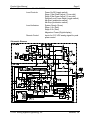
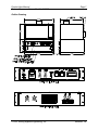
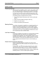
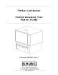
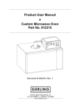
Product User Manual ♦ Custom Microwave Oven Part No. 910883 Document # 930022, Rev. 2 November 2001 P.O. Box 580816 ♦ Modesto, CA 95358 www.2450mhz.com Product User Manual Custom Microwave Oven – Part No. 910883 REV. 1 2 REVISION HISTORY DESCRIPTION PROTOTYPE RELEASE ADDED POWER CALIBRATION PROCEDURE Page 2 DATE 13DEC01 03JAN02 APPROVAL JFG JFG WARRANTY Products manufactured and sold by Gerling Applied Engineering, Inc. (“GAE”) are warranted to be free of defects in materials and workmanship under normal use and service for a period of twelve (12) months from the date of original shipment. GAE’s obligation under this warranty is limited to repairing or replacing, at GAE’s option, all nonconsumable component parts. Consumable parts are specifically excluded from this warranty and may include, but are not be limited to, magnetrons, fuses, lamps, seals, orings, v-belts, and fluids. All warranty repairs are to be done at GAE’s facility or as otherwise authorized by GAE. All shipping charges for warranty repair or replacement are the purchaser’s responsibility unless otherwise agreed to by GAE. This warranty supercedes all other warranties, expressed or implied. No warranty is given covering the product for any particular purpose other than as covered by the applicable product specifications. GAE assumes no liability in any event for incidental or consequential damages, financial losses, penalties or other losses incurred in conjunction with the use of GAE products. DOCUMENT CONVENTIONS NOTE: Means the reader should take note. Notes contain helpful information, suggestions, or references to other sections, chapters, or documents. CAUTION: Means the reader should be careful. You are doing something that might result in equipment damage or loss of data. WARNING: Means danger. A situation exists that could cause bodily injury or death. All personnel must be aware of the hazards involved with high voltage electrical circuitry and high power microwave devices. 2001 Gerling Applied Engineering, Inc. Modesto, CA Product User Manual Custom Microwave Oven – Part No. 910883 Page 3 WARNING The microwave oven described in this manual is capable of producing a microwave field that is potentially hazardous to operating personnel. The unit must never be connected or operated in a manner that allows a field in excess of 10 milliwatts per square centimeter to be generated in an area accessible to operating personnel. Contact GAE, Inc. for technical support prior to installation and/or operation of these units if there is any question or concern about microwave leakage. All electrical cable connections must be secure prior to operation. Never operate the microwave oven without a properly rated absorbing load inside the oven cavity. To ensure safe operation and prevent microwave leakage, the equipment must be periodically inspected and maintained as required or recommended. 2001 Gerling Applied Engineering, Inc. Modesto, CA Product User Manual Custom Microwave Oven – Part No. 910883 Page 4 TABLE OF CONTENTS EQUIPMENT DESCRIPTION ......................................................................................... 5 General Specifications Schematic Diagram Outline Drawing 5 6 7 INSTALLATION ............................................................................................................. 8 Preliminary Inspection Mounting Position Line Power Connection Remote Control and Interlock Connections Timer Programming Stage 1 Duration Stage 2 Duration 8 8 8 8 9 9 9 OPERATION ................................................................................................................ 10 Basic Oven Operation Control Power Standby Mode Operate Mode Microwave Power Adjustment (Local) Remote Microwave Power Adjustment Magnetron Current Meter 10 10 10 10 11 11 11 OVEN POWER CALIBRATION PROCEDURE ........................................................... 12 Equipment Required Initial Conditions Procedure Output Power Calculation 12 12 13 13 MAINTENANCE ........................................................................................................... 14 Magnetron Removal and Replacement 2001 Gerling Applied Engineering, Inc. 14 Modesto, CA Product User Manual Custom Microwave Oven – Part No. 910883 Page 5 EQUIPMENT DESCRIPTION The microwave oven described in this manual was custom designed by GAE, Inc. for Sherwin Williams Company for use in their product development laboratories. It was designed for use in conjunction with a humidity control system supplied by the Nyle Corporation of Bangor, Maine. The primary purpose of the custom oven system is to provide a means to quickly dry test samples of paint under controlled ambient conditions. The goal is to maintain consistency and repeatability between drying runs under same test conditions, and between multiple systems in use at either the same or different lab locations. To achieve the above goal, a special control system has been developed for use with a custom modified Garland/Sanyo model EMS100 commercial microwave oven. This control system provides variable average power control of the microwave oven that can be adjusted either locally or remotely via an analog control voltage provided externally. Also provided is a two-stage programmable timer that allows the operator to set the duration and microwave power level of each stage. An external interlock device may be connected that will prevent operation in the event the external interlock function is not satisfied. The controls provided with the microwave oven remain unchanged and can be used separately from the custom controls. All safety related functions of the microwave oven also remain unmodified and fully functional. General Specifications Microwave Power 1000 Watts rated output (per original oven manufacturer’s specification) Power Control Variable duty cycle from zero to 100% in 4% increments; 417 millisecond time base Input Power 110-120 VAC, 60 Hz, 15 Amp max. Turntable Standard oven turntable covered with hightemp silica cloth Cavity Ventilation Oven cavity modified for connection to 4” inlet and outlet air ducts; All other cavity perforations sealed Oven Interlocks Oven door; Magnetron over-temp Remote Interlock Connections for dry contact switch rated for 120 VAC, 1/4 Amp Cycle Timer 2-Stage digital programmable timer, EagleSignal model B856-511 2001 Gerling Applied Engineering, Inc. Modesto, CA Product User Manual Custom Microwave Oven – Part No. 910883 Page 6 Local Controls Power On/Off (toggle switch) Stage 1 Mw Power Adjust (10-turn dial) Stage 2 Mw Power Adjust (10 turn dial) Remote/Local Power Adjust (toggle switch) Mw Start (pushbutton switch) Mw Stop (pushbutton switch) Local Indicators System Ready (Green) Stage 1 On (Red) Stage 2 On (Red) Magnetron Power (Digital display) Remote Control Inputs for 0-10 VDC analog signal for peak power control Schematic Diagram 2001 Gerling Applied Engineering, Inc. Modesto, CA Product User Manual Custom Microwave Oven – Part No. 910883 Page 7 Outline Drawing 2001 Gerling Applied Engineering, Inc. Modesto, CA Product User Manual Custom Microwave Oven – Part No. 910883 Page 8 INSTALLATION Preliminary Inspection Upon arrival at the installation site the custom oven system should be thoroughly inspected for damage or wear caused during shipping. Any visible damage to the packaging material or the magnetron head itself should be noted and reported immediately to the shipping company in accordance with standard claims procedures. The following items are supplied with the system: 1. Custom Oven System (microwave oven, control module and cabinet) 2. Fabric covered turntable and support roller ring 3. Original oven user manual 4. Product User Manual (this document) Mounting Position The custom oven system is supplied as an integral assembly consisting of the modified microwave oven, control module control cabinet. It must be mounted upright on a level surface capable of supporting its weight. Sufficient clearance must be provided at the top and rear of the oven to allow adequate ventilation and connection to the inlet and outlet ventilation ducts. Line Power Connection Line power is supplied to the system by connecting the oven power cord (located at the rear of the oven) to a standard 120 VAC grounded outlet receptacle. The circuit supplying voltage to the receptacle must be rated for at least 15 Amps of continuous current draw. Although a 15 Amp fuse is provided inside the oven, the line power supply circuit should also be fused or circuit breaker protected. Remote Control and Interlock Connections Remote control and interlock connections are made to the 6position terminal block (TB1) located on the rear panel of the control module. Positions TB1-1 and TB1-2 are to be connected to a dry contact type interlock device rated for 120 VAC, ¼ Amp, that provides a short circuit connection when the interlock function is satisfied. In the absence of an external interlock device, connect a jumper wire between positions 1 and 2 to enable system operation. 2001 Gerling Applied Engineering, Inc. Modesto, CA Product User Manual Custom Microwave Oven – Part No. 910883 Page 9 For remote control of microwave peak power, connect a 0-10 VDC analog signal between positions TB1-3 and TB1-4 with the positive (+) side connected to TB1-3. Timer Programming The control module includes a multifunction digital timer which can be programmed directly from the front panel. The operating instructions supplied by the timer manufacturer have been provided as a supplement to this Product Use Manual as a reference for user programming. The timer has been preprogrammed for the “Delay/Interval” operating function which provides 2-stage timer functionality. WARNING: The control module circuitry requires the timer to be programmed for the “Delay/Interval” operating function ONLY. Operating the oven system with the timer programmed for a different operating function can result in faulty and possibly unsafe system operation. Stage 1 Duration Use the numeric keys 1 through 4 to adjust the Stage 1 duration from 1 to 9999 seconds. Once set, the value will be retained for each consecutive cycle until readjusted by the operator. Stage 2 Duration The duration of Stage 2 may be programmed by pressing the “P” button and holding down for 3 seconds. This puts the timer into “Program Mode” where it will stay until a) the “P” button is again pressed and held for 3 seconds, or b) there has been no key activity for 60 seconds. Once in Program Mode, press the “P” button twice to enter the Interval Time parameter (“int” appears on the top line of the LCD display). Use the 1 thru 4 keys to set the value in the range of 0.1 to 999.9 seconds. 2001 Gerling Applied Engineering, Inc. Modesto, CA Product User Manual Custom Microwave Oven – Part No. 910883 Page 10 OPERATION Basic Oven Operation The microwave oven can be operated independently of the custom controls by means of the original oven control panel. The custom controls need not be turned on or operating to use the oven in this manner. All safety related functions of the original oven remain fully operational. However, no preprogramming of the original oven controls has been done by the oven manufacturer or GAE. Consult the oven operating instructions supplied by the oven manufacturer (provided with this manual) for detailed operating and programming instructions. NOTE: Operation of the microwave oven independently of the custom controls will not be disabled by opening the external interlock contacts. Control Power Line power is available to the custom control module whenever line power is supplied to the oven and the oven door is closed. Turning on the POWER switch on the control module front panel supplied line power to and enable the control circuitry which is evidenced by the timer display. Unplugging the oven from the line power source, opening its door or turning off the POWER switch will remove line power from and disable the custom control circuitry altogether. Standby Mode Once line power has been supplied to the control circuitry, the READY indicator will turn on if the external interlock device is closed. The system is then in Standby mode and ready to start generating microwave power. Opening the contacts of the external interlock device or pressing the STOP button will return the system to Standby mode and turn off microwave power. Operate Mode Once in Standby mode, the two stage operating cycle can be started by pressing the START button. Microwave energy will then be delivered to the oven cavity at power levels determined by the settings of the POWER ADJUST dials for each stage of operation. Upon pressing the START button the cycle timer display will begin counting down in seconds and the STAGE 1 indicator will be on. After the first stage has counted down the STAGE 1 indicator will 2001 Gerling Applied Engineering, Inc. Modesto, CA Product User Manual Custom Microwave Oven – Part No. 910883 Page 11 turn off, the STAGE 2 indicator will turn on and the “Interval Time“ will begin to count down on the timer display. After completion of the second stage, microwave power will turn off and the timer will be automatically reset to display the Stage 1 duration setting. Pressing the STOP button at any time during operation, or opening the contacts of the external interlock device, will stop the generation of microwave power and return the system to Standby mode. Microwave Power Adjustment (Local) The average microwave power delivered by the oven can be controlled locally using the two POWER ADJUST dials located on the front panel. The REMOTE ANALOG / LOCAL selector switch must be in the LOCAL position to enable power control using the front panel dials. Two dials are provided for independent power control during each stage of the operating cycle. The dials can be adjusted either before or during cycle operation. The dial readings when multiplied by ten (x10) provide an approximate indication of the percentage of microwave output power. Remote Microwave Power Adjustment The average microwave power can also be controlled remotely using a 0-10 VDC analog control signal (see the previous section for connection information). The REMOTE ANALOG / LOCAL selector switch must be in the REMOTE ANALOG position to enable remote power control. The same analog control signal is used to control microwave power during both stages of the operating cycle. The percentage of microwave power generated is approximately equal to ten times (x10) the voltage delivered. Power can be adjusted at any time before or during operation. Magnetron Current Meter The digital LED meter on the control module front panel provides a relative indication of average magnetron current which correlates to the approximate level of microwave power being generated by the magnetron. The actual power level will depend on factors relating the type, size and location of the power absorbing load placed inside the oven cavity. This meter reading should never be construed to be an accurate measure of microwave power delivered to and absorbed by the load. However, in conjunction with the calibration procedure outlined in the next section, the meter reading can be used to monitor and verify oven performance. 2001 Gerling Applied Engineering, Inc. Modesto, CA Product User Manual Custom Microwave Oven – Part No. 910883 Page 12 OVEN POWER CALIBRATION PROCEDURE The procedure outlined in this section can be used to correlate the MAGNETRON CURRENT meter reading with actual microwave power delivered by the oven for a specific load. It is derived from the international standard IEC 60705 (3rd Edition, 1999-04) used worldwide by microwave oven manufacturers for performance measurement. NOTE: This procedure utilizes a standardized water load for calibration. As with any microwave oven, the actual power generated may vary with different load types, sizes and locations within the oven cavity. However, the performance variation between two different loads will remain constant as long as both loads remain unchanged. The procedure involves heating the water from a starting temperature below ambient temperature to approximately ambient temperature using energy from the microwave oven. This enables a reasonably accurate compensation for heat loss to the container. The procedure may be performed at any microwave power setting as may be required for calibration of normal operation. Equipment Required • Cylindrical container made of borosilicate glass (Pyrex) with outside diameter of approximately 190 mm, height of approximately 90 mm and maximum thickness of 3 mm • Potable (tap) water, approximately 1000 grams • Thermocouple probe thermometer capable of accurately measuring the temperature of the water • IR optopyrometer capable of accurately measuring the temperature of the empty container • Scale capable of accurately measuring the weight of the container, both empty and filled with water • Line voltage to be within the range per the oven specifications and within +/-1 % of the voltage to be supplied during normal operation. • Ambient temperature to be 20 °C +/-5 °C. • The temperature of the microwave oven power supply components to be within +/-5 °C of ambient. This condition can usually be met by not operating the oven for a few hours. External forced air cooling may be used to shorten this time. Initial Conditions 2001 Gerling Applied Engineering, Inc. Modesto, CA Product User Manual Custom Microwave Oven – Part No. 910883 Page 13 Procedure 1. Adjust both Stage 1 and Stage 2 microwave power settings on the control panel to the same desired power level. 2. Set the cycle timer on the control panel as follows: Stage 1: 2 seconds (this allows filament warm-up) Stage 2: A value (t) equal to 52 seconds multiplied by the ratio of full output power to the set output power (i.e. for half power setting the Stage 2 cycle time should be 104 seconds). 3. Adjust the water temperature to 10 °C +/- 1 °C before putting it into the container. Ice chips may be used to lower the temperature, but the ice should be completely melted prior to heating. 4. Accurately measure and record the container mass (mc) in grams. Note: Steps 5 through 10 should be done in rapid succession to minimize heat loss and temperature measurement error. 5. Accurately measure and record the initial container temperature (T0) in degrees Celsius. 6. Accurately measure and record the initial water temperature (T1) in degrees Celsius. 7. Pour the water into the container and accurately measure and record the filled container weight. Subtract the empty container weight (mc) to obtain the actual water weight (mw) in grams. 8. Place the filled container inside the oven cavity, centered on the turntable, and close the oven door. 9. Press the Start button on the control panel to turn on microwave power. During Stage 2, record the reading of the Magnetron Current meter. Allow the system to operate through both cycle stages. The oven will turn off automatically. 10. Upon completion of Stage 2, open the oven door and accurately measure and record the final water temperature (T2) in degrees Celsius. Gentle stirring will provide a more accurate measurement of average temperature. Output Power Calculation Calculate the microwave output power using the following formula: P = [4.187 ∗ mw (T2 – T1) + 0.55 ∗ mc (T2 – T0)]/t The meter reading recorded in step 9 above now corresponds to the calculated output power. 2001 Gerling Applied Engineering, Inc. Modesto, CA Product User Manual Custom Microwave Oven – Part No. 910883 Page 14 MAINTENANCE The custom microwave oven is designed to be maintenance free with the exception of magnetron replacement. The magnetron is considered a consumable component and is expected to fail within 1000 to 3000 of operation depending on operating conditions and usage. No calibration is necessary. In the event of damage due to improper operation or mishandling, the system should be returned to GAE for repair. Contact GAE for information on repair services. Magnetron Removal and Replacement The magnetron used in the custom microwave oven is the same as that supplied with the original oven by its manufacturer. Replacement of the magnetron can be done by technical personnel properly trained for repair of residential and commercial microwave ovens. 2001 Gerling Applied Engineering, Inc. Modesto, CA