1
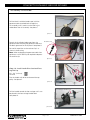
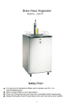
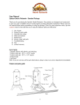
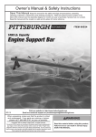
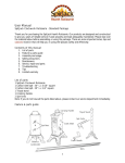
UNPACKING AND ASSEMBLY
CONCEPT2 DYNAMIC INDOOR ROWER
Assembly Instructions
Step 1. Open the two boxes and remove all the parts. Lay out the parts as shown below and read
through the assembly instructions before beginning assembly. Note: The clear plastic shield located
on the top of the flywheel is the optional Wind Shield. See Additional Notes for usage on page 9.
Wind Shield
Foot Carriage
Flywheel
Return
Assembly
Handle
Rail Assembly
Shuttle
Channel
Front Leg/Monitor Arm Assembly
Rear Foot
Parts for Assembly
2 20-penny nails
2 PN 2226 T27 6 lobe drive x
1/2” patched rev. ss
1 Rail Assembly
End Stop w/2 nuts
9 PN 2239 T27 6 lobe drive x
3/8” patched rev. ss
Installation
leader tape
(Located in plastic
bag with manuals)
1 Front Leg End Cap
1 6 lobe Driver
11 PN 2228 T27 6 lobe drive
x 1 3/8” patched rev. ss
Page 2
0811
CONCEPT2.COM
CONCEPT2 DYNAMIC INDOOR ROWER
Assembly Instructions
Step 2: Attach Rear Foot to Flywheel Box Assembly
(2) 3/8” (.95 cm)
PN 2239
Be sure that caster wheels point back, as shown
in the photo of the assembled Dynamic Indoor
Rower on page 9. Install the two screws and
tighten snugly. See photo A.
photo A
Before turning the flywheel box assembly right
side up to continue with assembly, inspect the
chain routing over the chain idler pulleys. See
image B. The chain should be routed around the
chain idler pulleys.
Step 3: Install Shuttle Channel
image B
(3) 3/8” (.95 cm)
PN 2239
Position the foot carriage and handle away from
the flywheel and on either side of the flywheel
return assembly with about equal lengths of the
drive cord leading to each part. See photo C.
Shuttle
Note: The drive cord is a single cord that is
attached to the handle on one end and the foot
carriage on the other end.
photo C
Important: Pull shuttle down by pulling on
drive cord so that the shuttle lies flat on the
return mechanism box. The drive cord should
be routed around the pulley as shown.
See photo D.
Remove the cardboard packaging from inside the
shuttle channel by sliding it out as indicated by the
arrow on the cardboard.
photo D
Note: The plastic “floor” remains in the
shuttle channel and is adhered at one end
only.
Position the shuttle channel with the slot
facing up, and the flange to the flywheel
side. The end with four holes in it should
be away from the flywheel. Place the
outstretched drive cord through the slot into the
shuttle channel so that the foot carriage and the
handle are on either side of the shuttle channel as
shown. See photo E.
photo E
Page 3
0811
CONCEPT2.COM
CONCEPT2 DYNAMIC INDOOR ROWER
Slide the shuttle channel into the rear leg with the
shuttle positioned inside the shuttle channel. See
image F. Be sure the drive cord going to the handle
and foot carriage are not twisted around each other.
image F
Shuttle
Start all three 3/8” screws through the flange of the
shuttle channel into the corresponding threaded holes
in the return mechanism box. Do not fully tighten the
screws until all three screws are in place. See photo G.
photo G
Step 4: Attach Rail Assembly to Flywheel
Assembly
Note: It will be helpful to have a second person
assist with this step.
(4) 3/8” (.95 cm)
PN 2239
Place the rail assembly as shown in photo H. Lift the
front end of the rail assembly up so that the bottom
lies flat against the top of the rear leg.
photo H
Start all four screws into the threaded holes. Do not
fully tighten the screws until all four screws are in
place. See photo I.
photo I
Step 5: Attach Seat Bungee
(1) 1 3/8” (3.49 cm)
PN 2228
Insert the screw through the round seat
bungee anchor and into the rear leg.
See photo J.
Seat Bungee
Hint: You will need to put tension on
the seat bungee to align the screw
with the threaded hole.
photo J
Page 4
0811
Seat Bungee
Anchor
CONCEPT2.COM
CONCEPT2 DYNAMIC INDOOR ROWER
Assembly continued
Step 6:
Slide Foot Carriage onto Rail Assembly
Slide foot carriage onto rail assembly
as shown in photo K. Make sure the
drive plate to the foot carriage extends
through the slot and into the shuttle
channel.
Pull the handle all the way out (away from the
flywheel) so that the drive cord is stretched out
straight in the shuttle channel. This action will cause
the foot carriage to move toward the flywheel.
See photo L. Again, be sure the drive cord going to the
handle and foot stretcher is not twisted around itself or
the drive plate.
Hint: Look into the open end of the shuttle channel to
ensure the drive cord is routed properly. The drive cord
attached to the handle should lay on the “floor” of the
shuttle channel and should not be wrapped around the
drive plate.
photo K
photo L
Step 7: Install Rail Assembly End Stop
(2) 1/2” (1.27 cm) PN 2226
(1) x Rail Assembly end stop w/2 nuts
Install the rail assembly end stop on the underside
of the rail assembly. Be sure nuts are oriented down
toward the floor. See photo M.
Rail Assembly
photo M
Shuttle Channel
Step 8: Attach Front Leg/Monitor Arm Assembly
(8) 1 3/8” (3.49 cm)
PN 2228
Note: You may need a second person to assist you
with aligning the holes.
Position the front leg/monitor arm assembly at end of
the shuttle channel and rail assembly. Lift the shuttle
channel and rail assembly up with one hand and slide
them between the two front legs taking care that the
handle is extended fully and the drive cord is routed
through the underside of the pulley. Take care not to
pinch the drive cord between the pulley guides and
the end of the shuttle channel. See photo N.
Page 5
Rail
Assembly
photo N
0811
Front Leg/
Monitor Arm
Assembly
Shuttle
Channel
CONCEPT2.COM
CONCEPT2 DYNAMIC INDOOR ROWER
Assembly continued
Front Leg/
Monitor Arm
Assembly
Hint: Insert one 20-penny nail through the top fastener
hole into the rail assembly and one 20-penny nail
through the top fastener hole into the shuttle channel
to temporarily align all fastener holes. Note that these
nails will be replaced with the screws. See photo O.
2
photo O
Rail Assembly
Once you have the parts aligned, insert screws but
do not fully tighten until all eight screws are in place.
Note that you may need to jostle the rail assembly and
shuttle channel to get the screws started.
See photo P.
1
Pulley
Guides
Pulley
photo P
Step 9: Install the Generator Cable
Uncoil the black installation leader tape by removing
the blue tape. DO NOT remove the white tape on the
end.
At the back end of the shuttle channel near the
flywheel, feed the white-taped end of the black
installation leader tape through the hole in the
underside of the rail assembly. See photo Q.
photo Q
Feed it all the way through the rail assembly until it
comes out the other end. See photo R.
photo R
Partially unwrap the white tape
and wrap it around the generator
cable plug, covering the plug.
See photo S.
photo S
Page 6
0811
CONCEPT2.COM
CONCEPT2 DYNAMIC INDOOR ROWER
Assembly continued
Pull the black installation leader tape (with the
generator cable attached) back through the
rail assembly until it comes out the hole in the
underside of the rail assembly. See photo T.
photo T
Detach the installation leader tape from the
generator cable and plug the generator cable into
the black generator on the flywheel. See photo U.
Retainer Clip
Generator
Be careful to position so the retainer clip is as
shown in the drawing.
Note: When unplugging the generator cable from
generator, a small tool may be required to depress
the retainer clip.
Generator
Cable
photo U
Top Pulley
Step 10: Install Handle Drive Cord and Front
Leg End Cap
(2) 1 3/8” (3.49 cm)
PN 2228
Run the handle with drive cord around the top
pulley. See photo V.
photo V
Foot Carriage Handle Hook
Pull the handle toward the foot carriage until it can
be placed in the foot carriage handle hook.
See photo W.
photo W
Page 7
0811
CONCEPT2.COM
CONCEPT2 DYNAMIC INDOOR ROWER
Monitor Arm
Front Leg
End Cap
Insert the front leg end cap over open end of front leg
where monitor arm joins the leg. Insert screws all the
way until the screw head meets the end cap. Even
though the screws will continue to spin, they are as
tight as they need to be. See photo X.
photo X
Front Leg
Step 11: FOR PM4 ONLY - Install Rechargeable
Battery Pack in the Performance Monitor (PM4)
(1) Rechargeable Battery Pack
Step 1
Step 2
Step 3
Page 8
0811
Step 4
CONCEPT2.COM
CONCEPT2 DYNAMIC INDOOR ROWER
Additional Notes
Setting the Level of the Dynamic Indoor Rower
The Dynamic Indoor Rower should be approximately level for the moving components to work properly.
Use the front foot leveling screws to fine tune the level as follows:
Have a friend watch you row:
• If the seat tends to stretch the bungee more to the front of the machine than the rear while rowing, raise
the front of the Dynamic Indoor Rower by turning both front foot leveling screws clockwise several turns.
• If the seat tends to stretch the bungee more to the rear of the machine than the front while rowing, lower
the front of the Dynamic Indoor Rower by turning both front foot leveling screws counter-clockwise several
turns.
Handle Return Tension
The design of the Dynamic Indoor Rower has allowed us to reduce the handle return tension significantly
compared to our Model D and E. Handle return tension, inherent in erg rowing, is not something we
experience in the boat. We therefore view the lower tension that can be achieved with this design as a positive
feature. The tension is set low when we ship the Dynamic Indoor Rower and we suggest rowing with it like
this for a while before choosing to tightening the bungee if you really want it to feel “more like an erg.” See
page 16 of the Dynamic Indoor Rower User Manual for directions.
Wind Shield
The clear plastic Wind Shield located on the top of the flywheel is an optional accessory designed to deflect air
coming from the flywheel away from the rower’s body. If you prefer the additional breeze, the Wind Shield can
be easily removed by bending it slightly and pulling the tabs at either end out of the flywheel enclosures.
Note: Using the Wind Shield will slightly reduce the current drag factor setting, making it feel like you’re
rowing in a slightly lower damper setting. The flywheel damper may be adjusted as needed to maintain the
desired feel. More about damper setting and drag factor can be found at concept2.com.
Maintenance
It is important that some simple steps be taken to ensure the proper working order and quality feel of the
Dynamic Indoor Rower.
1. Inspect the drive cord for wear and replace if excessive wear is visible.
2. Clean the seat and rail assembly, including the foot carriage rails, after every workout.
3. Clean and lubricate the chain.
For complete instructions on performing proper maintenance see page 16 of the Dynamic Indoor Rower
User Manual.
Front Leg/
Monitor Arm
Assembly
Foot Carriage
Wind Shield
Rail Assembly
Flywheel
Front Foot
Leveling Screws
Shuttle Channel
Caster Wheel
Page 9
0811
CONCEPT2.COM