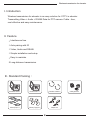
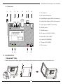
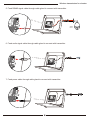
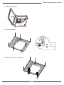
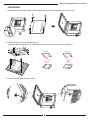
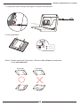
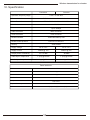
1
Wireless Transmission For Elevator
User Manual
Wireless transmission for elevator
The default value of digital code pairing is done before delivery.
If the transmission isn’t available, please accord below steps to
re-pairing again
Pairing process
Press the pair keys of transmitter and receiver. Both of them will search
each other to finish setting with encryption. when the “Link” light is on, that
means successful.
Note:
1. The pairing is successful after delivery.
2. After successful pairing process, while the Link light is off, it shows that
there is no connection between the transmitter and the receiver.
It means the transmission rage is a little too far to connect between
the transmitter and the receiver. The reception between the transmitter &
the receiver is not stable. Please reduce the distance between the
transmitter and the receiver until it works.
Notes :
a. Please connect antenna to Transmitter / Receiver firstly then power on.
b. Panel antenna is directional. Please keep both Panel antennas
face - to - face
c. Elevator moves fast for passengers.
Before installation, please make sure the elevator operation is under
controlled by elevator manager.
d. Please confirm the power supply voltage from elevator system is available
for our wireless devices.
1
Wireless transmission for elevator
I. Introduction
Wireless transmission for elevator is an easy solution for CCTV in elevator.
Transmitting Video + Audio + RS485 Data for PTZ camera. Cable - free,
cost effective and easy maintenance.
II. Feature
• Interference free
• Auto pairing with ID
• Video, Audio and RS485
• Simple installation and setup
• Easy to maintain
• Long distance transmission
III. Standard Packing :
PWR
PAIR
Video
LINK
RS485
LINK
PWR
Audio
RS485
PAIR
Video
Audio
Transmitter box X 1
Receiver box X 1
Extension cable X 2
Mount (Flat) X 4
Mount (Z type) X 2
Adaptor X 2
2
Cable gland X 2
Wireless transmission for elevator
IV. Transmitter / Receiver
Transmitter / Receiver are both built-in the boxes. Together with the boxes,
Please keep Transmitter / Receiver away from water, dirt, collision, ...or any
other damage. Before touching Transmitter / Receiver, please wear gloves
to anti-static electricity.
a. Transmitter
1
2
3
4
5
6 7
8
1. To antenna
2. TX means Transmitter
3. Audio(Right) input (RCA Connector)
4. Audio(Left) input (RCA Connector)
5. Video input (BNC Connector)
6. RS485 Output -
Video
7. RS485 Output +
8. DC input (5.5 Ø DC JACK)
Transmitter
9. Data LED (YELLOW)
10. Link LED (GREEN)
RS485
LINK
11. Power LED (RED)
PWR
PAIR
9
10
11
12
3
12. Pair button
Wireless transmission for elevator
b. Receiver
1
2
3
4
5
6 7
8
1. To antenna
2. RX means Receiver
3. Audio(Right) input (RCA Connector)
4. Audio(Left) Output (RCA Connector)
5. Video output (BNC Connector)
6. RS485 input -
Video
7. RS485 input +
8. DC input (5.5 Ø DC JACK)
Receiver
9. Data LED (YELLOW)
10. Link LED (GREEN)
LINK
RS485
11. Power LED (RED)
PWR
PAIR
9
10
11
12. Pair button
12
V. Installation
(TRANSMITTER)
1. Install waterproof cable gland, fixed boards and antenna accessory on transmitter box.
RS485
PWR
PAIR
Video
4
LINK
PWR
Audio
Audio
RS485
LINK
Video
PAIR
Wireless transmission for elevator
2. Locate transmitter box on the elevator.
(Depending situation on bottom or top)
3. Connect antenna extension cable.
PWR
PAIR
RS485
LINK
Video
PWR
PAIR
4. Feed video signal cable through cable gland to connect with transmitter.
t
LINK
LINK
tter
Video
Transmi
RS485
itter
Transm
RS485
Video
PWR
PAIR
PWR
PAIR
5
LINK
Audio
Speed
Dome
Audio
RS485
Video
Wireless transmission for elevator
5. Feed RS485 signal cable through cable gland to connect with transmitter.
t
LINK
Transmi
LINK
itter
RS485
Transm
RS485
tter
Video
PWR
Video
PAIR
Speed
Dome
PWR
PAIR
6. Feed audio signal cable through cable gland to connect with transmitter.
t
LINK
Transmi
RS485
LINK
Transm
RS485
Mic
tter
itter
Video
PWR
Video
PAIR
7. Feed power cable through cable gland to connect with transmitter.
t
LINK
itter
Transm
RS485
Video
LINK
Transmi
tter
RS485
PWR
Video
PWR
PAIR
PAIR
6
Wireless transmission for elevator
8. Tighten cable gland
LINK
Transmi
RS485
tter
Video
PWR
PAIR
9. Close and fasten
1 indicates lock
0 indicates unlock
10. Use brackets to fix on elevator.
7
Wireless transmission for elevator
(RECEIVER)
1. Install waterproof cable gland, fixed boards and antenna accessory on receiver box.
RS485
PWR
PAIR
PAIR
Video
LINK
PWR
Audio
RS485
LINK
Video
Audio
2. Locate receiver box on the elevator pit.
(Please notice the grooves of transmitter and receiver are at the same direction.)
Transmitter
Transmitter
Receiver
Receiver
3. Connect antenna extension cable.
LINK
PWR
PAIR
RS485
LINK
PWR
PAIR
8
Audio
Video
Audio
RS485
Video
Wireless transmission for elevator
4. Feed video signal cable through cable gland to connect with Receiver.
t
LINK
Receiv
RS485
To DVR video input
er
LINK
Receiver
RS485
Video
Video
PWR
PAIR
PWR
PAIR
5. Feed RS485 signal cable through cable gland to connect with Receiver.
t
LINK
LINK
er
Receiver
RS485
Receiv
RS485
To RS485 control device
Video
PWR
Video
PAIR
PWR
PAIR
6. Feed audio signal cable through cable gland to connect with Receiver.
t
LINK
Video
itter
Receiver
RS485
LINK
Transm
RS485
To DVR audio input
PWR
Video
PAIR
9
Wireless transmission for elevator
7. Feed power cable through cable gland to connect with Receiver.
t
LINK
Receiv
e
RS485
r
Video
LINK
Receiver
RS485
PWR
Video
PWR
PAIR
PAIR
8. Close and fasten
1 indicates lock
0 indicates unlock
Notice : Please make both (Transmitter / Receiver) face to face and keep them
on the same direction.
Transmitter
Transmitter
Receiver
Receiver
10
Wireless transmission for elevator
VI. Specification
Transmitter
Receiver
Operation frequency range
2.400 ~ 2.483 GHz
Channel switch
FHSS mode / Auto channel selection
Video Resolution
NTSC : 720 X 480 / PAL : 704 X 576
Modulation
16QAM
Data rate
Up to 12Mbps
Video connector
BNC connector
Audio connector
RCA connector
RS485 baudrate
1200/2400/4800 by auto
RS485 control protocol
PELCO D / PELCO P
Latency
500mS MAX
Supply voltage
DC 9 ~12 V
DC 9 ~12 V
Supply current
300mA @ 12V
300mA @ 12V
Output power / Sensitivity
18 +/-2 dBm
-80 dBm
Video input / output level
1 Vp-p @75 ohm
1 Vp-p @75 ohm
Audio input / output level
2.4 Vp-p @ 75 ohm
2.2 Vp-p 75 ohm
Panel antenna
Gain
14dBi
Beamwidth horizontal
20 degree
Beamwidth vertial
20 degree
VSWR
≤ 1.5 : 1
Impedance
50Ω ± 5Ω
Operation temperature
-10°C ~ +50°C
Measurement
253(L) x 253(W) x 70mm(H)
11