1
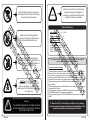
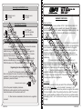
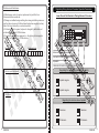
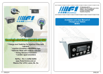
Instalation and User Manual of
Electronic Timing Advance Processors:
BLASTER, EAGLE, HAWK, SPARROW and VIPER.
Timing Advance
Processors
* Change-over Switches for Injection fitted with
indicator
* Injectors Emulators UNIVERSAL type
* Switches fitted with reserve indicator
* Timing Advance Processors
* Lambda signal emulators
BLASTER
Tel/Fax.: 54-11-4262-6249
www.f1electronica.com.ar
Máximo Paz 1276, Lanús, Bs. As.
ENGLISH
ENGLISH
Install the timing advance processor in
vertial position so as to prevent the entry
of water inside the processor
Inform end user that in case the timing
advance processor is damaged, an
emergency connector that restores the
original connection is available.
S.O.S.
Technical Features.
Input voltage:
ºC
Always locate the timing advance
processor far away from heat sources,
such as exhaust manifolds, etc...
10 - 14 Vdc
Advance regulation: 6º - 15º
Unit measurements:
Fixing hole diameter = 6mm approx.
Height = 106mm approx.
Width = 62mm approx.
Depth = 27mm approx.
Always locate the timing advance
processor far away from the ignition coil
and make sure the electric installation is
far from high voltage cables.
NEVER open the timing advance
processor unit, If this occurs while the
vehicle is operating, you run the risk of
electrocution and the product’s warranty is
no longer valid.
!
2
ENGLISH
For the proper installation of timing advance processors in the different
vehicles, please refer to the diagrams attached.
General connection standards:
The timing advance processor is placed in the vehicle's ignition signal between the
Electronic Control Unit and the ignition module. After cutting the cable from said
signal, the end coming from the control unit must be connected to the timing
advance processor's BLACK cable, and the cable end coming from the ignition
module must be connected to the timing advance processor's BROWN cable.
The timing advance processor's RED cable must be connected at 12V through the
ignition switch.
The timing advance processor's BLUE cable must be connected to the fuel changeover switches GAS output.
The timing advance processor's PURPLE cable must be connected to the TPS or
FLOWMETER signal that changes during acceleration.
The timing advance processor's YELLOW-GREEN cable must be connected to firm
MASS.
Electrical connections must be welded and properly
isolated.
THE PROPER OPERATION OF THE TIMING ADVANCE
PROCESSOR DEPENDS ON FOLLOWING THE ABOVEMENTIONED INSTRUCTIONS
F1 Electrónica S.R.L. Shall assume no liability for any damage
caused to people or things resulting from the manipulation of the
product by third parties not authorized to that effect.
ENGLISH
7
Selecting the ADVANCE Curve
5
Advance curve
for CNG
5
Advance curve
for LPG
Selecting the TPS Type
6
For TPS with
0V to 5V variation
(normal TPS)
6
For TPS with
5V to 0V variation
(reverted TPS)
WARRANTY CERTIFICATE
Dear customer:
Congratulations on your purchase of this F1 Electrónica product. All
our products undergo rigorous quality tests. However, if the product
features any kind of defect, please address your installer urgently, who
will make the necessary checkups or will intervene as necessary.
General Warranty Information:
How and when to apply the advance during deceleration and at idle
In some vehicles it is convenient to remove the advance
during deceleration or at idle, so as to prevent irregular
malfunctioning. On the other hand, it is convenient to apply the
advance during acceleration to reduce the possibility of counterexplosions to a minimum.
Timing advance processors may apply or remove the
advance automatically by connecting the advance processors’
PURPLE cable to the TPS potentiometer or air flowmeter.
Regulating the Advance Intervention
As the TPS or flowmeter position when the vehicle is at
idle is not always the same, the advance intervention point may be
regulated. This is achieved by regulating the timing advance
processor’s preset as follows:
Advance intervention register
A) Turn the preset completely clockwise.
B) While the vehicle is at idle, turn the preset slowly
counterclockwise until the advance led is off.
If, after minimum acceleration, the led turns on, regulation
is correct.
6
ENGLISH
This product is warranted by F1 Electrónica for a period of 12
(twelve) months from the date of installation. Defects in manufacturing
and materials, as well as defects in everything related to the good
operation of the equipment will be covered. Should the product be
defective during the warranty period, F1 Electrónica will repair or
replace the defective parts. Shipping expenses will be borne by the
addressee.
Components or accessories not manufactured by F1
Electrónica will be covered only by the warranties of their respective
manufacturers. This warranty is the only one provided by F1
Electrónica. Therefore, any other warranty is excluded.
F1 Electrónica shall assume no liability for any damage
against individuals or things resulting from product misfunction, except
in the event of gross deceit or intent. This warranty will be valid only for
those who are not late in payments.
Conditions:
This warranty will only be valid if this certificate is submitted,
which shall be fully filled in, and, enclosed, if necessary, to the
purchase receipt. F1 Electrónica may refuse to recognize this warranty
if it is incomplete or false. This warranty will only be valid if the product
was in good operating conditions at the moment of purchase and its
packaging, intact, as F1 Electrónica is the only one that may warranty
its origin.
ENGLISH
3
Exclusions and Limitations:
Regulating Timing Advance Processor Operation Parameters.
a) Maintenance, control, repair or replacement of parts that have
deteriorated after normal use.
b) Damage or malfunctioning resulting from wrong installation, misuse or
use that does not agree with the technical instructions supplied, and any
defect that is not caused by a construction defect.
c) Products installed, repaired, replaced or changed by individuals not
authorized in writing by F1 Electrónica.
d) Accidents caused by force majeure (i.e.: fire, water, electromagnetic
fields, etc.) not controlled by F1 Electrónica.
Serial Nr.:
Lower View of the Electronic Timing Advance Processor
1 2 3 4 5 6
ONê
Installation Date:
Advance indicator led applied.
Connector for electrical installation.
Dipswitch
Advance intervention preset, that regulates TPS
Regulating the number of cylinders in the vehicle
Vehicle model and brand:
4-cylinder engine
1 2
5-cylinder engine
1 2
6-cylinder engine
1 2
8-cylinder engine
1 2
Fitter Stamp:
Regulating the advance amount applied
6º advance
3 4
9º advance
3 4
12º advance
3 4
4
ENGLISH
15º advance
3 4
ENGLISH
5