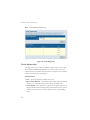
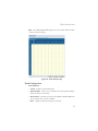
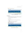
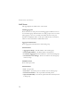
1
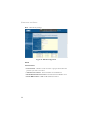
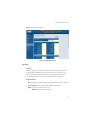
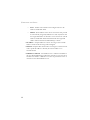
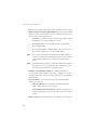
TigerSwitch 10/100/1000
Managed Ethernet Switch
◆
◆
◆
◆
◆
◆
◆
◆
◆
◆
24 auto-MDI/MDI-X 10/100/1000BASE-T ports
4 ports shared with 4 SFP transceiver slots
Non-blocking switching architecture
Spanning Tree Protocol
Up to eight LACP or static 8-port trunks
Layer 2/3/4 CoS support through four priority queues
Full support for VLANs
IGMP multicast filtering and snooping
Support for jumbo frames up to 9 KB
Manageable via console, Web, SNMP/RMON
Management Guide
SMC8024L2
TigerSwitch 10/100/1000
Installation Guide
From SMC’s Tiger line of feature-rich workgroup LAN solutions
38 Tesla
Irvine, CA 92618
Phone: (949) 679-8000
April 2006
Pub. # 150000022900H
Information furnished by SMC Networks, Inc. (SMC) is believed to be accurate and reliable. However, no
responsibility is assumed by SMC for its use, nor for any infringements of patents or other rights of third
parties which may result from its use. No license is granted by implication or otherwise under any patent or
patent rights of SMC. SMC reserves the right to change specifications at any time without notice.
Copyright © 2006 by
SMC Networks, Inc.
38 Tesla
Irvine, CA 92618
All rights reserved. Printed in Taiwan
Trademarks:
SMC is a registered trademark; and EZ Switch, TigerStack and TigerSwitch are trademarks of SMC
Networks, Inc. Other product and company names are trademarks or registered trademarks of their
respective holders.
LIMITED WARRANTY
Limited Warranty Statement: SMC Networks, Inc. (“SMC”) warrants its products to be
free from defects in workmanship and materials, under normal use and service, for the
applicable warranty term. All SMC products carry a standard 90-day limited warranty from
the date of purchase from SMC or its Authorized Reseller. SMC may, at its own discretion,
repair or replace any product not operating as warranted with a similar or functionally
equivalent product, during the applicable warranty term. SMC will endeavor to repair or
replace any product returned under warranty within 30 days of receipt of the product.
The standard limited warranty can be upgraded to a Limited Lifetime* warranty by registering
new products within 30 days of purchase from SMC or its Authorized Reseller. Registration
can be accomplished via the enclosed product registration card or online via the SMC Web
site. Failure to register will not affect the standard limited warranty. The Limited Lifetime
warranty covers a product during the Life of that Product, which is defined as the period of
time during which the product is an “Active” SMC product. A product is considered to be
“Active” while it is listed on the current SMC price list. As new technologies emerge, older
technologies become obsolete and SMC will, at its discretion, replace an older product in its
product line with one that incorporates these newer technologies. At that point, the obsolete
product is discontinued and is no longer an “Active” SMC product. A list of discontinued
products with their respective dates of discontinuance can be found at:
http://www.smc.com/index.cfm?action=customer_service_warranty.
All products that are replaced become the property of SMC. Replacement products may be
either new or reconditioned. Any replaced or repaired product carries either a 30-day limited
warranty or the remainder of the initial warranty, whichever is longer. SMC is not responsible
for any custom software or firmware, configuration information, or memory data of
Customer contained in, stored on, or integrated with any products returned to SMC pursuant
to any warranty. Products returned to SMC should have any customer-installed accessory or
add-on components, such as expansion modules, removed prior to returning the product for
replacement. SMC is not responsible for these items if they are returned with the product.
Customers must contact SMC for a Return Material Authorization number prior to returning
any product to SMC. Proof of purchase may be required. Any product returned to SMC
without a valid Return Material Authorization (RMA) number clearly marked on the outside
of the package will be returned to customer at customer’s expense. For warranty claims within
North America, please call our toll-free customer support number at (800) 762-4968.
Customers are responsible for all shipping charges from their facility to SMC. SMC is
responsible for return shipping charges from SMC to customer.
i
WARRANTIES EXCLUSIVE: IF AN SMC PRODUCT DOES NOT OPERATE AS
WARRANTED ABOVE, CUSTOMER’S SOLE REMEDY SHALL BE REPAIR OR
REPLACEMENT OF THE PRODUCT IN QUESTION, AT SMC’S OPTION. THE
FOREGOING WARRANTIES AND REMEDIES ARE EXCLUSIVE AND ARE IN
LIEU OF ALL OTHER WARRANTIES OR CONDITIONS, EXPRESS OR IMPLIED,
EITHER IN FACT OR BY OPERATION OF LAW, STATUTORY OR OTHERWISE,
INCLUDING WARRANTIES OR CONDITIONS OF MERCHANTABILITY AND
FITNESS FOR A PARTICULAR PURPOSE. SMC NEITHER ASSUMES NOR
AUTHORIZES ANY OTHER PERSON TO ASSUME FOR IT ANY OTHER
LIABILITY IN CONNECTION WITH THE SALE, INSTALLATION,
MAINTENANCE OR USE OF ITS PRODUCTS. SMC SHALL NOT BE LIABLE
UNDER THIS WARRANTY IF ITS TESTING AND EXAMINATION DISCLOSE THE
ALLEGED DEFECT IN THE PRODUCT DOES NOT EXIST OR WAS CAUSED BY
CUSTOMER’S OR ANY THIRD PERSON’S MISUSE, NEGLECT, IMPROPER
INSTALLATION OR TESTING, UNAUTHORIZED ATTEMPTS TO REPAIR, OR
ANY OTHER CAUSE BEYOND THE RANGE OF THE INTENDED USE, OR BY
ACCIDENT, FIRE, LIGHTNING, OR OTHER HAZARD.
LIMITATION OF LIABILITY: IN NO EVENT, WHETHER BASED IN CONTRACT
OR TORT (INCLUDING NEGLIGENCE), SHALL SMC BE LIABLE FOR
INCIDENTAL, CONSEQUENTIAL, INDIRECT, SPECIAL, OR PUNITIVE
DAMAGES OF ANY KIND, OR FOR LOSS OF REVENUE, LOSS OF BUSINESS, OR
OTHER FINANCIAL LOSS ARISING OUT OF OR IN CONNECTION WITH THE
SALE, INSTALLATION, MAINTENANCE, USE, PERFORMANCE, FAILURE, OR
INTERRUPTION OF ITS PRODUCTS, EVEN IF SMC OR ITS AUTHORIZED
RESELLER HAS BEEN ADVISED OF THE POSSIBILITY OF SUCH DAMAGES.
SOME STATES DO NOT ALLOW THE EXCLUSION OF IMPLIED WARRANTIES
OR THE LIMITATION OF INCIDENTAL OR CONSEQUENTIAL DAMAGES FOR
CONSUMER PRODUCTS, SO THE ABOVE LIMITATIONS AND EXCLUSIONS
MAY NOT APPLY TO YOU. THIS WARRANTY GIVES YOU SPECIFIC LEGAL
RIGHTS, WHICH MAY VARY FROM STATE TO STATE. NOTHING IN THIS
WARRANTY SHALL BE TAKEN TO AFFECT YOUR STATUTORY RIGHTS.
* SMC will provide warranty service for one year following discontinuance from the active
SMC price list. Under the limited lifetime warranty, internal and external power supplies, fans,
and cables are covered by a standard one-year warranty from date of purchase.
SMC Networks, Inc.
38 Tesla
Irvine, CA 92618
ii
TABLE OF CONTENTS
Introduction . . . . . . . . . . . . . . . . . . . . . . . . . . . . . . . . . . . 1
Features and Benefits . . . . . . . . . . . . . . . . . . . . . . . . . . . . . . . . . . . . . . . . . . 1
Initial Configuration . . . . . . . . . . . . . . . . . . . . . . . . . . . . 2
Configuring the Switch . . . . . . . . . . . . . . . . . . . . . . . . . . 4
Using the Web Interface . . . . . . . . . . . . . . . . . . . . . . . . . . . . . . . . . . . . . . . 4
Navigating the Web Browser Interface . . . . . . . . . . . . . . . . . . . . . . . . . . . . 5
Home Page . . . . . . . . . . . . . . . . . . . . . . . . . . . . . . . . . . . . . . . . . . . . 5
Configuration Options . . . . . . . . . . . . . . . . . . . . . . . . . . . . . . . . . . . 6
Panel Display . . . . . . . . . . . . . . . . . . . . . . . . . . . . . . . . . . . . . . . . . . . 6
Main Menu . . . . . . . . . . . . . . . . . . . . . . . . . . . . . . . . . . . . . . . . . . . . 7
Web Configuration . . . . . . . . . . . . . . . . . . . . . . . . . . . . . . . . . . . . . . . . . . . . 9
Displaying Status Overview . . . . . . . . . . . . . . . . . . . . . . . . . . . . . . . 9
Showing Port Statistics . . . . . . . . . . . . . . . . . . . . . . . . . . . . . . . . . . 13
Displaying System Name . . . . . . . . . . . . . . . . . . . . . . . . . . . . . . . . 16
Setting the Switch’s IP Address . . . . . . . . . . . . . . . . . . . . . . . . . . 17
Configuring the Logon Password . . . . . . . . . . . . . . . . . . . . . . . . . 18
Tools . . . . . . . . . . . . . . . . . . . . . . . . . . . . . . . . . . . . . . . . . . . . . . . . 19
Register Product . . . . . . . . . . . . . . . . . . . . . . . . . . . . . . . . . . . . . . . 22
Static MAC . . . . . . . . . . . . . . . . . . . . . . . . . . . . . . . . . . . . . . . . . . . 22
Counter Config . . . . . . . . . . . . . . . . . . . . . . . . . . . . . . . . . . . . . . . . 23
Port Configuration . . . . . . . . . . . . . . . . . . . . . . . . . . . . . . . . . . . . . 24
Configuring Rate Limits . . . . . . . . . . . . . . . . . . . . . . . . . . . . . . . . . 25
Storm Control . . . . . . . . . . . . . . . . . . . . . . . . . . . . . . . . . . . . . . . . . 27
Port Mirroring . . . . . . . . . . . . . . . . . . . . . . . . . . . . . . . . . . . . . . . . . 28
Cable Diagnostic . . . . . . . . . . . . . . . . . . . . . . . . . . . . . . . . . . . . . . . 29
Trunks Membership . . . . . . . . . . . . . . . . . . . . . . . . . . . . . . . . . . . . 30
Trunk Configuration . . . . . . . . . . . . . . . . . . . . . . . . . . . . . . . . . . . . 31
Trunk Rate Limit . . . . . . . . . . . . . . . . . . . . . . . . . . . . . . . . . . . . . . 32
LACP Setup . . . . . . . . . . . . . . . . . . . . . . . . . . . . . . . . . . . . . . . . . . 33
LACP Status . . . . . . . . . . . . . . . . . . . . . . . . . . . . . . . . . . . . . . . . . . 34
VLAN Settings . . . . . . . . . . . . . . . . . . . . . . . . . . . . . . . . . . . . . . . . 35
vii
QOS Settings . . . . . . . . . . . . . . . . . . . . . . . . . . . . . . . . . . . . . . . . . 38
RSTP . . . . . . . . . . . . . . . . . . . . . . . . . . . . . . . . . . . . . . . . . . . . . . . . 40
802.1X . . . . . . . . . . . . . . . . . . . . . . . . . . . . . . . . . . . . . . . . . . . . . . . 43
Security . . . . . . . . . . . . . . . . . . . . . . . . . . . . . . . . . . . . . . . . . . . . . . 47
IGMP Snoop . . . . . . . . . . . . . . . . . . . . . . . . . . . . . . . . . . . . . . . . . 52
SNMP . . . . . . . . . . . . . . . . . . . . . . . . . . . . . . . . . . . . . . . . . . . . . . . 55
Troubleshooting . . . . . . . . . . . . . . . . . . . . . . . . . . . . . . .57
Diagnosing Switch Indicators . . . . . . . . . . . . . . . . . . . . . . . . . . . . . . . . . . 57
Changing a PC’s IP Address . . . . . . . . . . . . . . . . . . . . .59
Software Specifications . . . . . . . . . . . . . . . . . . . . . . . . . .61
Software Features . . . . . . . . . . . . . . . . . . . . . . . . . . . . . . . . . . . . . . . . . . . . 61
Management Features . . . . . . . . . . . . . . . . . . . . . . . . . . . . . . . . . . . . . . . . 62
Standards . . . . . . . . . . . . . . . . . . . . . . . . . . . . . . . . . . . . . . . . . . . . . . . . . . 63
Management Information Bases . . . . . . . . . . . . . . . . . . . . . . . . . . . . . . . . 64
viii
FEATURES AND BENEFITS
INTRODUCTION
The Tiger Switch SMC8024L2 is a high performance managed switch that
delivers performance and control to your network. It provides 24
full-duplex 1000BASE-T ports that significantly improve network
performance and boost throughput using features configured through the
web interface. With 48 Gigabits of throughput bandwidth, these switches
provide the quickest solution to meeting the growing demands on your
network.
Features and Benefits
•
•
•
•
User friendly web-management interface
Supports Qos, Spanning Tree, IGMP, VLANs and trunk configuration
Store-and-forward switching ensures error-free transmission
Half- and full-duplex flow control prevents packets from being dropped
under heavy loading
• Plug-and-play—optional configuration using web interface
• “At-a-glance” LEDs for port and system status monitoring
• Desktop or rack installation
1
INITIAL CONFIGURATION
INITIAL CONFIGURATION
To make use of the management features of your Tiger Switch, you must
first configure it with an IP address that is compatible with the network it
is being installed in. For simplicity, this should be done before you
permanently install the switch in the network.
The following procedure is recommended:
1. Place your Tiger Switch close to the PC that you will use to configure
it. It will help if you can see the front panel of the switch while
working on your PC.
2. Connect the Ethernet port of your PC to any port on the front panel
of your Tiger Switch. Connect power to the switch and verify that you
have a link by checking the front-panel LEDs. (See the Hardware
Description on page 2 for more information on the LEDs.)
3. The default IP address of the switch is 192.168.2.10 and the subnet
mask is 255.255.255.0. If your PC has a different IP address from the
switch but is on the same subnet (i.e. the PC and switch both have
addresses that start 192.168.2.x ) you can skip directly to step 4.
Otherwise, you must set your PC’s IP address manually. If you are
unfamiliar with this process, see “Changing a PC’s IP Address” on
page 7.
4. Open your web browser and enter the address http://192.168.2.10. If
your PC is properly configured, you will see the login page of your
Tiger Switch. If you do not see the login page, please check your IP
address and repeat step 3.
5. Enter the default password "smcadmin" and click on the Login
button.
2
FEATURES AND BENEFITS
6. From the menu, click on SYSTEM, then click on LAN Settings. On
the LAN Settings page, enter the new IP address, Subnet Mask and
Gateway IP Address for the switch, then click on the APPLY button.
No other configuration changes are required at this stage, but it is
recommended that you change the administrator’s password before
logging out. To change the password, click SYSTEM, Password, and then
fill in all the fields on the Password Settings page before clicking on the
APPLY button.
3
CONFIGURING THE SWITCH
CONFIGURING THE SWITCH
Using the Web Interface
This switch provides an embedded HTTP web agent. Using a web browser
you can configure the switch and view statistics to monitor network
activity. The web agent can be accessed by any computer on the network
using a standard web browser (Internet Explorer 5.5 or above, or Mozilla
Firefox 1.0 or above).
Prior to accessing the switch from a web browser, be sure you have first
performed the following tasks:
1. Configure the switch with a valid IP address, subnet mask, and default
gateway. (Default: 192.168.2.10/255.255.255.0/0.0.0.0)
(See “Initial Configuration” on page 2.)
2. Set a new password using the web interface. (Default: “smcadmin”).
Access to the web interface is controlled by the password.
(See “Configuring the Logon Password” on page 18.)
Note:
4
If, at any point, you cannot remember the switch's IP address,
you can restore the original settings by following the procedure
described in the "Troubleshooting" section.
NAVIGATING THE WEB BROWSER INTERFACE
Navigating the Web Browser Interface
To access the web-browser interface you must first enter a password. The
user has Read/Write access to all configuration parameters and statistics.
The default password for the switch is “smcadmin.” If user input is not
detected within five minutes, the current session will be terminated.
Home Page
When your web browser connects with the switch’s web agent, the home
page is displayed as shown below. The home page displays the Main Menu
on the left side of the screen and System Information on the right side.
The Main Menu links are used to navigate to other menus, and display
configuration parameters and statistics.
Figure 1 Home Page
5
CONFIGURING THE SWITCH
Configuration Options
Configurable parameters have a dialog box or a drop-down list. Once a
configuration change has been made on a page, be sure to click on the
Apply button to confirm the new setting. The following table summarizes
the web page configuration buttons.
Table 1 Web Page Configuration Buttons
Button
Action
Apply
Sets specified values to the system.
Cancel
Discards all changes and restores current values.
Help
Links directly to web help.
Notes:
To ensure proper screen refresh, be sure that Internet Explorer
is configured as follows: Under the menu “Tools / Internet
Options / General / Temporary Internet Files / Settings,” the
setting for item “Check for newer versions of stored pages”
should be “Every visit to the page.”
Panel Display
The web agent displays an image of the switch’s ports. The port will turn
green when the corresponding front-panel port is in connection with
another device. To show the port number, place mouse pointer onto the
intended port.
Figure 2 Front Panel Indicators
6
NAVIGATING THE WEB BROWSER INTERFACE
Main Menu
Using the onboard web agent, you can define system parameters, manage
and control the switch, and all its ports, or monitor network conditions.
The following table briefly describes the selections available from this
program.
Table 2 Switch Main Menu
Menu
Description
STATUS
Page
9
Overview
Provides basic system description, including
system information, address information, port
information, trunk information, and VLAN
information.
Statistics
Shows statistics for port, interface, and
RMON.
SYSTEM
9
13
16
Name
Shows the name of the switch.
16
LAN Settings
Sets LAN IP address, subnet mask, and
gateway IP address.
17
Password
Changes password.
18
Tools
19
Restore to Factory
Defaults
Force the Switch to perform a power reset
and restore the original factory settings.
19
Upgrade Firmware
Upgrade the Switch system firmware using a
file provided by SMC.
20
Restart
Restarts the switch.
21
Register Product
Registers the switch online.
22
Static MAC
Creates Static MAC addresses.
22
Counter Config
Selects which statistics to count and show.
23
Configure the speed and duplex mode of the
port.
24
PORTS
Settings
24
7
CONFIGURING THE SWITCH
Table 2 Switch Main Menu (Continued)
Menu
Description
Rate Limiting
Sets the rate limiting parameters for each port
on the Switch
25
Storm Control
Sets the broadcast storm control parameters
for every port on the Switch.
23
Port Mirroring
Sets up the port mirroring features of the
switch to enable traffic monitoring.
28
Cable Diagnostic
Diagnoses cable faults.
29
TRUNKS
30
Membership
Specifies ports to group into static trunks
31
Settings
Configures trunk connection settings
31
Rate Limiting
Sets the rate limiting parameters for each
Trunk configured on the Switch.
32
LACP Setup
Sets link aggregation.
33
LACP Status
Shows the LACP groups status.
34
VLANS
33
VLAN Membership
Sets VLAN group.
35
VLAN Port Config
Configures the VLANs on the switch for both
Ports and Trunks.
33
QOS
Settings
38
Sets the priority of packets within the switch.
38
Settings
Sets up RSTP configuration.
41
Status
Shows RSTP bridge and port status.
42
RSTP
40
802.1X
43
Settings
Sets up 802.1X configuration.
44
Statistics
Displays the 802.1x statistics collected by the
switch.
46
Security
IP Filter
8
Page
47
Setus up IP filter.
47
WEB CONFIGURATION
Table 2 Switch Main Menu (Continued)
Menu
Description
Port Security
Sets security policy for port.
ACL
Sets up management access filter.
IGMP Snoop
Page
49
51
52
Settings
Sets up IGMP Snooping configuration
54
Status
Shows IGMPSNOOP instances and port
states.
54
SNMP
Settings
LOGOUT
55
Sets up SNMP agent.
55
Quits to the Login page.
Web Configuration
Displaying Status Overview
You can easily identify the system by displaying the device name, location
and contact information.
Field Attributes
System Information
• System Name – Name assigned to the switch system.
• Number of Ports – Number of built-in ports.
• Hardware Version – Hardware version of the main board.
• Code Version – Version number of the code.
• Serial Number – The serial number of the switch.
Address Information
• Management VLAN – ID of the configured VLAN (this is set to 1 and
cannot be changed) all ports on the unit are members of VLAN 1. The
management station must always be attached to a port on VLAN 1.
• IP Address – Address of the VLAN to which the management station
9
CONFIGURING THE SWITCH
is attached. (Note that the management station must always be on VLAN
1) Valid IP addresses consist of four numbers, 0 to 255, separated by
periods.
• Subnet Mask – This mask identifies the host address bits used for
routing to specific subnets. (Default: 255.255.255.0)
• Gateway IP Address – IP address of the gateway router between the
stack and management stations that exist on other network segments.
(Default: 0.0.0.0)
• MAC Address – The physical layer address.
Port Information
• Type – Indicates the port type.
• Link Status – Indicates if the link is Up or Down.
• Speed/Duplex Status – Shows the current speed and duplex mode.
Displays a number, the speed in Mbps, followed by either "fdx" for
full-duplex or "hdx" for half-duplex.
• Flow Control Status – Indicates whether flow control is enabled or
disabled.
• Autonegotiation – Shows if auto-negotiation is enabled or disabled.
• Frame Type – Either "Tagged" or "All". "Tagged" means that the port
will only send and receive VLAN-tagged packets. When set to "All", the
port will also send and receive untagged packets.
• PVID – VLAN ID assigned to untagged frames received on the
interface. (Default: 1)
Trunk Information
• Trunk – The trunk label. "T1" through "T8" are used as trunk labels.
• Type – All trunks and ports on this switch are 10/100/1000M
• Trunk Status – An indication of the speed and duplex setting of the
trunk. This is a number, the speed in Mbps, followed by either “Full” for
full-duplex or “Half” for half-duplex. This can be changed on the
TRUNKS > Settings page.
• Ports – The ports that are members of the trunk.
10
WEB CONFIGURATION
VLAN Inoformation
• VLAN ID – A number in the range 1 - 4094 which identifies the VLAN.
• VLAN Member – A list of the ports that are members of the VLAN.
By default, all ports are members of VLAN 1.
11
CONFIGURING THE SWITCH
Web – Click STATUS, Overview.
Figure 3 Switch Information
12
WEB CONFIGURATION
Showing Port Statistics
You can display statistics on network traffic from the ports. These statistics
can be used to identify potential problems with the switch (such as a faulty
port or unusually heavy loading). All values displayed have been
accumulated since the last system reboot, but can be reset to zero by
clicking the CLEAR button. The current statistics are not displayed until
you click the REFRESH button.
Table 3 Port Statistics
Parameter
Description
Interface Statistics
Received Octets
The total number of octets received on the interface,
including framing characters.
Received Unicast Packets
The number of subnetwork-unicast packets delivered
to a higher-layer protocol.
Received Errors
The number of inbound packets that contained errors
preventing them from being deliverable to a
higher-layer protocol.
Transmitted Multicast
Packets
The total number of packets that higher-level
protocols requested be transmitted, and which were
addressed to a multicast address at this sub-layer,
including those that were discarded or not sent.
Transmitted Broadcast
Packets
The total number of packets that higher-level
protocols requested be transmitted, and which were
addressed to a broadcast address at this sub-layer,
including those that were discarded or not sent.
Received High Priority
Packets
The total number of received packets that set as High
Priority in the QoS settings.
Transmitted High Priority The total number of transmitted packets that set as
Packets
High Priority in the QoS settings.
Received Multicast Packets The number of packets, delivered by this sub-layer to
a higher (sub-)layer, which were addressed to a
multicast address at this sub-layer.
13
CONFIGURING THE SWITCH
Table 3 Port Statistics (Continued)
Parameter
Description
Received Broadcast
Packets
The number of packets, delivered by this sub-layer to
a higher (sub-)layer, which were addressed to a
broadcast address at this sub-layer.
Transmitted Octets
The total number of octets transmitted out of the
interface, including framing characters.
Transmitted Unicast
Packets
The total number of packets that higher-level
protocols requested be transmitted to a
subnetwork-unicast address, including those that
were discarded or not sent.
Transmitted Errors
The number of outbound packets that could not be
transmitted because of errors.
Received Normal Priority
Packets
The total number of received packets that set as High
Priority in the QoS settings.
Transmitted Normal
Priority Packets
The total number of transmitted packets that set as
High Priority in the QoS settings.
RMON Statistics
14
Drop Events
The total number of events in which packets were
dropped due to lack of resources.
Received Frames
The total number of frames (bad, broadcast and
multicast) received.
Multicast Frames
The total number of good frames received that were
directed to this multicast address.
Undersize Frames
The total number of frames received that were less
than 64 octets long (excluding framing bits, but
including FCS octets) and were otherwise well
formed.
Fragments
The total number of frames received that were less
than 64 octets in length (excluding framing bits, but
including FCS octets) and had either an FCS or
alignment error.
Collisions
The best estimate of the total number of collisions on
this Ethernet segment.
WEB CONFIGURATION
Table 3 Port Statistics (Continued)
Parameter
Description
Received Bytes
Total number of bytes of data received on the
network. This statistic can be used as a reasonable
indication of Ethernet utilization.
Broadcast Frames
The total number of good frames received that were
directed to the broadcast address. Note that this does
not include multicast packets.
CRC/Alignment Errors
The number of CRC/alignment errors (FCS or
alignment errors).
Oversize Frames
The total number of frames received that were longer
than 1518 octets (excluding framing bits, but
including FCS octets) and were otherwise well
formed.
Jabbers
The total number of frames received that were longer
than 1518 octets (excluding framing bits, but
including FCS octets), and had either an FCS or
alignment error.
64 Bytes Frames
The total number of frames (including bad packets)
received and transmitted that were 64 octets in length
(excluding framing bits but including FCS octets).
65-127 Byte Frames
128-255 Byte Frames
256-511 Byte Frames
512-1023 Byte Frames
1024-1518 Byte Frames
The total number of frames (including bad packets)
received and transmitted where the number of octets
fall within the specified range (excluding framing bits
but including FCS octets).
15
CONFIGURING THE SWITCH
Web – Click STATUS, Statistics.
Figure 4 Port Statistics
Displaying System Name
You can easily identify the system by displaying the device name.
Field Attributes
• Switch Name – Name assigned to the switch system.
16
WEB CONFIGURATION
Web – Click System, Name.
Figure 5 System Name
Setting the Switch’s IP Address
This section describes how to configure an IP interface for management
access over the network. The IP address for this switch is 192.168.2.10 by
default. To manually configure an address, you need to change the switch’s
default settings (IP address 192.168.2.10 and netmask 255.255.255.0) to
values that are compatible with your network. You may also need to a
establish a default gateway between the switch and management stations
that exist on another network segment.
Field Attributes
•
DHCP Enabled – Clciik to select the box to enable DHCP. (default:
enabled)
•
LAN IP Address – Address of the VLAN interface that is allowed
management access. Valid IP addresses consist of four numbers, 0 to
255, separated by periods. (Default : 192.168.2.10)
•
Subnet Mask – This mask identifies the host address bits used for
routing to specific subnets. (Default: 255.255.255.0)
•
Gateway IP Address – IP address of the gateway router between this
device and management stations that exist on other network segments.
(Default: 0.0.0.0)
Note:
If, at any point, you cannot remember the switch's IP address,
you can restore the original settings by following the procedure
described in the "Troubleshooting" section.
17
CONFIGURING THE SWITCH
Manual Configuration
Web – Click System, LAN Settings. Enter the IP address, subnet mask and
gateway, then click APPLY.
Figure 6 LAN Settings
Configuring the Logon Password
The administrator has write access for all parameters governing the
onboard agent. You should therefore assign a new administrator password
as soon as possible, and store it in a safe place.
Field Attributes
•
Password – Specifies the user password.
(Range: 1-16 characters plain text, case sensitive)
Note:
18
If, at any point, you cannot remember the password, you can
restore the original settings by following the procedure described
in the "Troubleshooting" section.
WEB CONFIGURATION
Web – Click System, Password. To change the password for the
administrator, enter current password, the new password, confirm it by
entering it again, then click APPLY.
Figure 7 Password Settings
Tools
On Tools page, you can restore the switch to default settings, upgrade the
firmware of the switch, or restart the switch.
Restore to Factory Defaults
Force the Switch to restore the original factory settings. To reset the
switch, select "Reset to Factory Defaults" from the drop-down list and
click APPLY. The LAN IP Address, Subnet Mask and Gateway IP Address
will not be reset.
19
CONFIGURING THE SWITCH
Web – Click System, Tools, Reset to Factory Defaults.
Figure 8 Reset to Factory Defaults
Upgrade Firmware
Upgrades the Switch system firmware using a file provided by SMC. Select
"Upgrade Firmware" from the Tools drop-down list then click on the
"Browse" button to select the firmware file. Finally, press the APPLY
button to upgrade the selected Switch firmware file. You can download
firmware files for your Switch from the Support section of www.smc.com.
Web – Click System, Tools, Reset to Factory Defaults.
Figure 9 Upgrade Firmware
20
WEB CONFIGURATION
Upload/Download Configuration
Web – Click SYSTEM, Tools, Upload/Download Configuration. To
upload or download the configuration file, select "Upload/Download
Configuration" from the Tools drop-down list, then click "Upload" or
"Download", and then click on the "Browse" button to select the file.
Figure 10 Upload/Download Configuration
Restart Switch
Web – Click SYSTEM, Tools, Restart Switch. To restart the switch, select
from the Tools drop-down list, and then click APPLY. The reset will be
complete when the user interface displays the login page.
Figure 11 Restart Switch
21
CONFIGURING THE SWITCH
Register Product
Register your product if you have not already done so.
Web – Click System, Register Product. By clicking the Register Now
button you will be taken to the SMC website, where you can enter the
products details.
Figure 12 Register Product
Static MAC
A static MAC address is an entry in MAC table which can not be aged out.
Add Static MAC
Type the static MAC address and associated VLAN ID (1-4095) into
corresponding fields in the Add Static MAC table. After pressing ADD
button, you will be navigated to a new page to configure the Destination
Mask for this MAC entry. Only one static MAC address can be added per
time.
Static MAC Address Configuration
This table shows the stored static MAC entries in MAC table. Symbol X
indicates that the corresponding bit for the port the symbol X respresents
is set to 1 in the destination mask. Click the radio button which is
associated with the static MAC entry that is displayed immediately at its
right side and use Modify or Delete button can modify or delete this entry.
Modify button will navigate to a web page for reconfiguring the
Destination Mask.
22
WEB CONFIGURATION
Web – Click System, Static MAC.
Figure 13 Static MAC Address Configuration
Counter Config
This page allows the customer to select the statistics to count and display.
It is possible to monitor 5 Transmit counters,5 receive counters as well as 1
transmit byte counter and receive byte counter at the same time. Please
also note the following restrictions.
Received Unicast Packets can be enabled after Received Multicast Packets
and Received Broadcast Packets are enabled.
Received Multicast Packets and Received Broadcast Packets can be
disabled after Received Unicast Packets is disabled.
The above 2 rules are also applied to Transmitted Multicast Packets,
Transmitted Unicast Packets and Transmitted Broadcast Packets.
23
CONFIGURING THE SWITCH
Web – Click PORTS, Settings.
Figure 14 Counter Configuration
Port Configuration
You can use the Port Configuration page to manually fix the speed, duplex
mode, and flow control.
Field Attributes
• Speed/Duplex – Allows you to manually set the port speed and duplex
mode.
• Flow Control – Allows flow control to be enabled or disabled. When the
box is checked, flow control is enabled.
• Trunk – Indicates if a port is a member of a trunk.
24
WEB CONFIGURATION
Web – Click PORTS, Settings.
Figure 15 Port Configuration
Configuring Rate Limits
This function allows the network manager to control the maximum rate
for traffic transmitted or received on an interface. Rate limiting is
configured on interfaces at the edge of a network to limit traffic into or out
of the switch. Traffic that falls within the rate limit is transmitted, while
packets that exceed the acceptable amount of traffic are dropped.
Rate limiting can be applied to individual ports or trunks. When an
interface is configured with this feature, the traffic rate will be monitored
by the hardware to verify conformity. Non-conforming traffic is dropped,
conforming traffic is forwarded without any changes.
The Input/Output Bandwidth Limit field is a type-in box which accepts an
integer number in the range 1 to 100. The number specifies the percentage
25
CONFIGURING THE SWITCH
of the total input bandwidth of the port that can be used before packets
are dropped or flow-control starts.
Web – Click PORTS, Rate Limiting. This page enables you to set the rate
limiting parameters for each port on the Switch.
Figure 16 Rate Limiting
26
WEB CONFIGURATION
Storm Control
Broadcast storms may occur when a device on your network is
malfunctioning, or if application programs are not well designed or
properly configured. If there is too much broadcast traffic on your
network, performance can be severely degraded or everything can come to
complete halt.
You can protect your network from broadcast storms by setting a
threshold for broadcast traffic for each port. Any broadcast packets
exceeding the specified threshold will then be dropped.
Field Attributes
• Type – List the type of traffic which can be rate limited, including ICMP,
Learn Frames, Broadcast, Multicast and Flooded Unicast frames.
• Enable Storm Control – Click to select the box to enable/disable the
storm control for the type of frames listed just in the left side of it.
• Rate(number of frame per second) – The Rate field is set by a single
drop-down list. The same threshold is applied to every port on the
switch. When the threshold is exceeded, packets are dropped,
irrespective of the flow-control settings.
27
CONFIGURING THE SWITCH
Web – Click PORTS, Storm Control. This page enables you to set the
broadcast storm control parameters for every port on the Switch.
Figure 17 Port Broadcast Control
Port Mirroring
You can mirror traffic from any source port to a target port for real-time
analysis. You can then attach a logic analyzer or RMON probe to the target
port and study the traffic crossing the source port in a completely
unobtrusive manner.
Field Attributes
Ports to Mirror
Select the ports that you want to mirror from this section of the page. A
port will be mirrored when the"Mirroring Enabled" check-box is checked.
• Port to Mirror to – The port that will “duplicate” or “mirror” the traffic
on the source port. Only incoming packets can be mirrored. Packets will
be dropped when the available egress bandwidth is less than ingress
bandwidth.
Note: If the total ingress bandwidth exceeds the mirror port's egress
bandwidth, packets will eventually be dropped on ingress to the
28
WEB CONFIGURATION
switch which means they will not reach the mirror port or their
intended destination port. Input rate-limiting in conjunction with
port flow-control could be used to ensure that the total ingress
bandwidth never exceeds the egress bandwidth.
Web – Click PORTS, Port Mirroring.
Figure 18 Port Mirroring
Cable Diagnostic
You can perform cable diagnostics for all ports or selected ports to
diagnose any cable faults (Short, Open etc..) and feedback a distance to the
fault.
Field Attributes
• Cable Diagnostics – It can be performed on a per-port basis. Select the
port that you want to do the cable diagnostics.
• Cable Status – Show the cable length, operating conditions and isolate
a variety of common faults that can occur on the CAT5 twisted pair
cabling.
29
CONFIGURING THE SWITCH
Web – Click PORTS, Port Mirroring.
Figure 19 Cable Diagnostics
Trunks Membership
This page allows you to create a maximum of eight trunks of up to eight
ports each. The Membership Table has one row for each port and ten
columns. Each row contains nine radio buttons which are used to indicate
which trunk (if any) the port belongs to.
Field Attributes
• Port – The front-panel port-number of the port.
• Not a Trunk Member – If the radio button in this column is selected,
the port is not a member of any trunks. This is the default state.
• Trunk T1-T8 – These columns correspond to the eight trunks that are
supported by the Switch. Clicking on the radio button in any one of these
columns causes the port to become a member of the corresponding
trunk.
30
WEB CONFIGURATION
Web – Click TRUNKS, Membership. Click to select which Trunk member
to which each port belongs.
Figure 20 Trunk Membership
Trunk Configuration
Field Attributes
• Trunk – Indicates trunk identification.
• Speed/Duplex – Allows you to manually set the port speed and duplex
mode for all ports in the trunk.
• Flow Control – Allows flow control to be enabled or disabled. When the
box is checked, flow control is enabled.
• Ports – Indicates which ports belong to the trunk.
31
CONFIGURING THE SWITCH
Web – Click TRUNKS, Settings.
Figure 21 Trunk Configuration
Trunk Rate Limit
This page allows you to change the maximum data-rate into and out of
each trunk on the switch.
Field Attributes
• Trunk – Indicates trunk identification.
• Trunk Speed – Indicates the trunk speed.
• Enable Input Rate Limiting - Click to select the box to enable the
Input Rate Limiting function.
• Input Limit – Enter the desired limit. (% of port speed)
• Enable Output Rate Limiting – Click to select the box to enable the
Output Rate Limiting function.
• Output Limit – Enter the desired limit. (% of port speed)
• Ports – Indicates which ports belong to the trunk.
32
WEB CONFIGURATION
Web – Click TRUNKS, Settings.
Figure 22 Trunk Rate Limiting
LACP Setup
This page enables you to setup the configuration of LACP on all or some
ports. LACP (IEEE 802.3ad Link Aggregation Protocol) provides a way to
set up aggregation automatically between switc
Field Attributes
• Port – The front-panel port-number of the port. This cannot be
changed.
• Enabled – Enable LACP on the associated port.
• Key Value – Setup key value for each port.
Web – Click TRUNKS, Settings.
Figure 23 LACP Port Configuration
33
CONFIGURING THE SWITCH
LACP Status
This page displays the LACP status of the switch.
LACP Aggregation
Shows the status of each port. The LACP Aggregation table has one row
for each LACP group. Normal means no LACP group is active. For active
LACP groups, a new row is created from which the status of its port
members are displayed. Status of each port is indicated by a colored box,
which use color and number to differentiate status.
Aggregation Information
Shows aggregation information for each LACP group.
Field Attributes
•
•
•
•
Aggregation Group - The ID number of the LACP group.
Partner MAC Address - The MAC address of link partner.
Local Ports Aggregated - Port member list of the local LACP group.
Seconds Since Last Change - Time in seconds for the LACP group
since last setup.
LACP Port Status
Shows LACP port status.
Field Attributes
•
•
•
•
34
Port - The port ID.
Port Active - Show if the port is a member of active LACP group.
Partner Port Number - List of port ID for the link partner.
Operational Port Key - The current operational value of the Key for the
LACP group.
WEB CONFIGURATION
Web – Click TRUNKS, LACP Status.
Figure 24 LACP Status Overview
VLAN Settings
You can configure VLAN behavior for specific interfaces, including the
default VLAN identifier (PVID) and accepted frame types. This page
allows you to create and delete VLANs (Virtual LANs) and to change the
VLAN membership and behaviour of individual ports. VLANs are
powerful but can be difficult to set up properly. Each row of the table
corresponds to one port or trunk; trunked ports cannot be configured
individually.
Introduction to VLANs
VLANs (or Virtual LANs) are logical partitions of the physical LAN. You
can use VLANs to increase network performance or increase internal
network security.
35
CONFIGURING THE SWITCH
If the network has adequate performance and security for your current
needs, it is recommended that you leave the VLAN settings in the default
configuration. The default configuration is as follows:
• All ports are members of VLAN 1
• The switch management interface is on VLAN 1 (this cannot be
changed)
• All ports have a Port VLAN ID (PVID) of 1
• All ports can send and receive both VLAN-tagged and untagged packets
(i.e. they are hybrid ports)
In the default configuration, any port is able to send traffic to any other
port and a PC connected to any port will be able ro reach the management
interface. Broadcast traffic, for example, will be flooded to all ports on the
switch.
There are three different parameters that can be configured for each port
on the switch; VLAN IDs (VLAN membership), PVID and Packet Type.
Note that the ports within a Trunk cannot be configured individually;
configure the Trunk instead (Trunks are labelled T1 to T8).
Field Attributes
• Port/Trunk – The front-panel port-number of the port or the ID of a
trunk. This cannot be changed.
• VLAN Awareness – VLAN aware ports will strip the VLAN tag from
received frames and insert the tag in transmitted frames (except PVID).
VLAN unaware ports will not strip the tag from received frames or insert
the tag in transmitted frames.
For QinQ application, customer port should be VLAN unaware and
network port (trunk port) should be VLAN aware.
• QinQ – QinQ enabled port will accept packets up to 1526 bytes in
length, which means double tag header frames can be accepted.
For QinQ application, the QinQ should be enabled for provider port but
not for customer port.
Note: For QinQ application, customer ports indicate those ports which
36
are connected to normal VLAN aware switches at the customer network
and the network ports are those which are connected to the service
provider network. To tunnel the packets through MAN, QinQ needs to
be enabled on network ports
• Packet Type – Sets the interface to accept all frame types, including
tagged or untagged frames, or only tagged frames. When set to receive
all frame types, any received frames that are untagged are assigned to the
default VLAN. PCs should be connected to ports with Packet Type set
to “All”. PCs cannot, in general, send or receive tagged packets. Switches
should be connected to each other with Packet Type set to “Tagged”. If
the Packet Type is set to “All”, the port can accept incoming tagged and
untagged packets. Untagged packets will be associated with the VLAN
identified by the PVID. Tagged packets will be dropped unless the port
is a member of the VLAN identified by the VLAN tag in the packet.
Outgoing packets will be tagged unless the packet's VLAN ID is the
same as the PVID. If the Packet Type is set to “Tagged”, the port will
drop untagged packets and will only send and receive tagged packets.
Tagged packets will be dropped unless the port is a member of the
VLAN identified by the VLAN tag in the packet. The PVID has no
effect in this case.(Option: All, Tagged; Default: All)
• PVID – VLAN ID assigned to untagged frames received on the
interface. The PVID is (Port VLAN ID) is the VLAN ID that is
associated with untagged, ingress packets. It is not possible to remove a
port from VLAN 1 unless its PVID has been changed to something other
than 1. The PVID has no effect on ports that have Packet Type set to
Tagged. (Default: 1)
CONFIGURING THE SWITCH
Web – Click VLANS, VLAN Settings. Fill in the required settings for each
interface, click Apply.
Figure 25 VLAN Settings
QOS Settings
QoS (Quality of Service) is a mechanism which is used to prioritize certain
traffic as it is moves through the switch. Traffic can be classified as High or
Normal priority and, when the switch is heavily loaded, it is the Normal
priority packets that are dropped first. You can select how traffic is
prioritized by using one of the four QoS modes which is selected using the
QoS Mode drop-down list.
Note:
Only one QoS mode can be active at one time. It is not possible,
for example, to prioritise traffic using the IP Port number and
802.1p tag.
QoS Disabled
QoS is turned off and all packets have equal priority.
38
WEB CONFIGURATION
802.1p
Packets are prioritzed using the content of the VLAN-tag. The 802.1p field
is held within the VLAN-tag of a packet. The field is three bits long so can
hold eight values; 0 - 7 inclusive. When QoS Mode is set to 802.1p, the
802.1p Configuration table appears which allows a priority (normal or
high) to be set for each of the eight values.
You can use the Prioritize Traffic drop-down list to quickly set the values
in the 802.1p Configuration table. Select All Normal Priority to set all
values to normal priority or select All High Priority to set all values to high
priority. Use Custom if you want to set each value individually.
Note: Because end-stations, like PCs, are not usually VLAN aware, they do
not create VLAN-tagged frames. As a result, this method of prioritization
is not ideal when there are a lot of PCs connected to the Switch.
DSCP
Packets are prioritized using the DSCP (Differentiated Services Code
Point) value.
The Differentiated Services Code Point (DSCP) is a six bit field that is
contained within an IP (TCP or UDP) header. Six bits allows the DSCP
field to take any value in the range 0 - 63 inclusive. When QoS Mode is set
to DSCP, the DSCP Configuration table appears which allows a priority
(normal or high) to be set for each of the DSCP values.
You can use the Prioritize Traffic drop-down list to quickly set the values
in the DSCP Configuration table. Select All Normal Priority to set all
values to normal priority or select All High Priority to set all values to high
priority. Use Custom if you want to set each value individually.
39
CONFIGURING THE SWITCH
Web – Click QOS, Settings. In QoS Mode, select QoS Diabled, 802.1p, or
DSCP to configure the related parameters.
Figure 26 QoS Settings
RSTP
RSTP is a protocol that prevents loops in the network and dynamically
reconfigures which physical links in a switch should forward frames.
STA Introduction
The Spanning Tree Algorithm (STA) can be used to detect and disable
network loops, and to provide backup links between switches, bridges or
routers. This allows the switch to interact with other bridging devices (that
is, an STA-compliant switch, bridge or router) in your network to ensure
that only one route exists between any two stations on the network, and
provide backup links which automatically take over when a primary link
goes down. The spanning tree algorithms supported by this switch are
STP, Spanning Tree Protocol (IEEE 802.1D), and RSTP, Rapid Spanning
Tree Protocol (IEEE 802.1w).
40
WEB CONFIGURATION
RSTP System Configuration
Field Attributes
• System Priority – This parameter configures the spanning tree priority
globally for this switch. The device with the highest priority becomes the
STA root device. However, if all devices have the same priority, the
device with the lowest MAC address will then become the root device.
Number between 0 - 61440 in increments of 4096. Therefore, there are
16 distinct values.
• Hello Time – Interval (in seconds) at which the root device transmits a
configuration message (BPDU frame). Number between 1 - 10 (default
is 2).
• Max Age – The maximum time (in seconds) a device can wait without
receiving a configuration message before attempting to reconfigure. That
also means the maximum life time for a BPDU frame. Number between
6 - 40 (default is 20).
• Forward Delay – The maximum time (in seconds) the root device will
wait before changing states (i.e., discarding to learning to forwarding).
Number between 4 - 30 (default is 15).
• Force Version – Set and show the RSTP protocol to use. Normal - use
RSTP, Compatible - compatible with STP.
RSTP Port Configuration
Field Attributes
• Port - The port ID. It can not be changed. Aggregations means any
configured trunk group.
• Enabled - Click on the tick-box to enable/disable the RSTP prototocl
for the port.
• Edge - Expect the port to be an edge port (linking to an end station) or
a link to another STP device.
41
CONFIGURING THE SWITCH
• Path Cost - This parameter is used by the STP to determine the best
path between devices. Therefore, lower values should be assigned to
ports attached to faster media, and higher values assigned to ports with
slower media. Set the RSTP pathcost on the port. Number between 0 200000000. 0 means autogenerated pathcost.
Web – Click RSTP, Settings.
Figure
26
Figure 27 RSTP Configuration
RSTP Status Overview
The RSTP Bridge Overview table has one row to display settings for the
whole switch. Hello Time, Maximum Age and Forward Delay are
displayed. Topology shows the switch current state. Root ID indicates the
root port ID for the switch.
RSTP Port Status
Shows the detailed RSTP information for each port.
42
WEB CONFIGURATION
Field Attributes
•
•
•
•
Port/Trunk - Port/Trunk ID number.
VLAN ID - VLAN IDs of the port.
Path Cost - Show the path cost on this port.
Edge Port - Yes if the port is an edge port which connects to an end
station.
• P2p Port - Yes if the port link is connected to another STP device.
• Protocol - Show the running protocol, RSTP or STP.
• Port State - Show the current port state, blocking, forwarding, learning
etc...
Web – Click RSTP, Status.
Figure 28 RSTP Status Overview
802.1X
Network switches can provide open and easy access to network resources
by simply attaching a client PC. Although this automatic configuration and
access is a desirable feature, it also allows unauthorized personnel to easily
43
CONFIGURING THE SWITCH
intrude and possibly gain access to sensitive network data. With IEEE
802.1X (dot1X), access to all switch ports in a network can be centrally
controlled from a server, which means that authorized users can use the
same credentials for authentication from any point within the network.
802.1 X Setting
The IEEE 802.1x standard defines a port-based access control procedure
that prevents unauthorized access to a network by requiring users to first
submit credentials for authentication.
Field Attributes
System Setting
• Mode - Indicates if 802.1x protocol is globally enabled or disabled on the
switch.
• RADIUS IP - Set RADIUS server IP address.
• RADIUS UDP Port - Set up UDP Port for the external RADIUS
server.
• RADIUS Secret - Set the secret shared between the switch and the
RADIUS server.
• Reauthentication Enabled - Sets the client to be re-authenticated after
the interval specified by the Re-authentication Period. Re-authentication
can be used to detect if a new device is plugged into a switch port.
• Reauthentication Period - Sets the time period after which a
connected client must be re-authenticated.
• EAP timeout - The time the switch shall wait for the supplicant
response before re-transmitting a packet.
Port Setting
• Port - The port ID. It can not be changed.
• Admin State - Sets the authentication mode to one of the following
options:
• Auto - Requires a dot1x-aware client to be authorized by the
authentication server. Clients that are not dot1x-aware will be
44
WEB CONFIGURATION
denied access.
•
Force-Authorized - Forces the port to grant access to all clients,
either dot1x-aware or otherwise.
•
Force-Unauthorized - Forces the port to deny access to all
clients, either dot1x-aware or otherwise.
• Port State - The state of the port.
• Reset - Two options available:
• Re-Authenticate - Schedules a reauthentication to whenever the
quiet-period of the port runs out.
•
Note:
Force-Reinitialize - Bypasses the quiet-period of the port and
enables immediate reauthentication regardless of the status for the
quiet-period.
The reason for a "quiet-period" follows: If a re-authentication
fails, the IEEE802.1X standard enforces a so-called
"quiet-period" in which the authenticator (switch) shall be quiet
and not re-try another authentication - also packets from
supplicant are discarded in this quiet period - this way
'brute-force' attacks are prevented.
45
CONFIGURING THE SWITCH
Web – Click 802.1X, Settings.
Figure 29 802.1X Configuration
802.1X
Field Attributes
• Port Statistics - Statistics can be viewed on a per-port basis. Select the
port that you want to view here.
• Authenticator counters - General statistics for authenticator.
• Backend Authenticator counters - General statistics for Radius server.
• Dot1x MIB counters - MIB module defined for 802.1x.
46
WEB CONFIGURATION
Web – Click 802.1X, Statistics.
Figure 30 802.1X Statistics
Security
IP Filter
On this page, you can setup the source IP Filter on all or some ports. It is
used to block unwanted access and provide access to the network for
either a specific source IP address or a specific subnet. The IP Filter
Configuration table has one row for each port and five columns.
Field Attributes
• Port - The front-panel port-number of the port. This cannot be changed.
• Source IP Filter - Set mode and IP addresses for IP filter.
• Mode - Select the mode for this port.
• Disabled - Disable source IP filter.
47
CONFIGURING THE SWITCH
•
Static - Enable source IP filter with configured values in IP
Address and IP Mask fields.
•
DHCP - The IP address for the device connected to this port will
be automatically assigned by DHCP server and only frames with
the assigned IP address are allowed to access the network. The IP
Address and IP Mask fields will be filled with the assigned IP
address and 255.255.255.255 individually by software.
• IP Address - Setup IP addresses to allow accessing. Frames with IP
address outside the allowed range will be dropped.
• IP Mask - Setup IP subnet mask to allow accessing for a subnet. If frame
with a specific IP address is allowed, the mask should be set to
255.255.255.255.
• DHCP Sever Allowed - Set if DHCP server is enabled or disabled on
this port. When DHCP Server Allowed is selected on a port, the port is
allowed to be linked to a DHCP server. This can prevent the access of
unwanted or unsolicited DHCP servers.
48
WEB CONFIGURATION
Web – Click Security, IP Filter.
Figure
30
Figure 31 IP Filter Configuration
Port Security
Port security is a feature that allows you to configure a port with one or
more MAC addresses that are authorized to access the network through
that port. The Port Security table has one row for each port and five
columns.
When port security is enabled on a port, the switch stops learning new
MAC addresses on the specified port when it has reached a configured
maximum number. Only incoming traffic with source addresses already
stored in the dynamic or static address table will be accepted as authorized
to access the network through that port. If a device with an unauthorized
MAC address attempts to use the switch port, the intrusion will be
detected and the switch can automatically take action which is specified in
Intrusion Action.
Field Attributes
49
CONFIGURING THE SWITCH
• Port - The front-panel port-number of the port. This cannot be changed.
• Allowed number of Learned MAC addresses - Set maximum of MAC
addresses which can be learned by this port. The Mode settings for the
port are set by a single drop-down list.
• No Limit - No limitation on the number of dynamcally learned
MAC address. Also means disable port security.
•
8/7/6/5/4/3/2/1 - The maximum number of dynamically
learned MAC address.
•
0 - No dynamically learned MAC address is allowed on this port.
But this has no influence on the static MAC address.
Note:
Port security only handles dynamically learned MAC addresses
and have no limitations on static MAC addresses. On this switch,
24 static MAC address can be configured by System > Static
MAC.
Note:
The MAC addresses already in the address table will be retained
and will not age out. Any other device that attempts to use the
port will be prevented from accessing the switch.
• Number of Learned MAC addresses - Display the number of
currently learned MAC addresses. The string '-' is displayed if a port is
setup with "No Limit" mode in the Allowed number of Learned MAC
addresses field.
• Intrusion Action - Action to be carried out if unauthorized MAC
addresses are detected.
• Deny New Stations - The station with unauthorized MAC
address will be denied to access the port.
•
Send Trap and Deny New Stations - Besides denying the new
station, trap message is sent by the switch to report an intrusion
action.
• Trunk - Display the trunk ID if the port is member of a trunk group.
50
WEB CONFIGURATION
Web – Click Security, Port Cecurity.
Figure 32 Port Security
ACL
This page enables you to setup management access filter on the switch.
With the Management Access Filter Configuration table, you can create a
list of up to 8 IP addresses or IP address groups that are allowed
management access to the switch through the web interface or SNMP. The
management interfaces are open to all IP addresses by default. Once you
add an entry to a filter list, access to that interface is restricted to the
specified addresses. If anyone tries to access a management interface on
the switch from an invalid address, the switch will reject the connection.
Note:
Invalid frames will not be able to access management interface,
but normal forwarding is not impacted.
51
CONFIGURING THE SWITCH
Web – Click Security, ACL.
Figure 33 Management Access Filter Configuration
IGMP Snoop
IGMPSNOOP monitors IGMP service requests passing between
multicast clients and servers, and dynamically configures the ports which
need to recieve the mulitcast traffic. For IGMPV3, basic support for
reports only, Source Multicast not supported.
Settings
Field Attributes
IGMP Snooping Configuration
• IGMP Enabled - When enabled, the switch will monitor network traffic
to determine which hosts want to receive multicast traffic.
• Router Ports - Set if ports are conneting to the IGMP administrative
routers.
52
WEB CONFIGURATION
• Unregistered IPMC Flooding enabled - Set forwarding mode for
unregistered (not-joined) IP multicast traffic. The traffic will flood when
enabled, and forward to router-ports only when disabled.
IGMP Snooping VLAN Configuration
• VLAN ID - The VLAN ID. It can not be changed.
• IGMP Snooping Enabled -When enabled, the port will monitor
network traffic to determine which hosts want to receive the multicast
traffic.
• IGMP Querying Enabled - When enabled, the port can serve as the
Querier, which is responsible for asking hosts if they want to receive
multicast traffic.
Web – Click IGMP Snoop, Settings.
Figure 34 IGMP Snooping Configuration
53
CONFIGURING THE SWITCH
IGMP Status
Show the IGMPSNOOP statistics for the whole switch.
Field Attributes
•
•
•
•
•
•
•
•
VLAN ID - VLAN ID number.
Querier - Show whether Querying is enabled.
Queries transmitted - Show the number of transmitted Query packets.
Queries received - Show the number of received Query packets.
v1 Reports - Show the number of received v1 Report packets.
v2 Reports - Show the number of received v2 Report packets.
v3 Reports - Show the number of received v2 Report packets.
v3 Leave - Show the number of v3 leave packets received.
Web – Click IGMP Snoop, Status.
Figure 35 IGMP Snoop Status
54
WEB CONFIGURATION
SNMP
Simple Network Management Protocol (SNMP) is a communication
protocol designed specifically for managing devices on a network.
Equipment commonly managed with SNMP includes switches, routers
and host computers. SNMP is typically used to configure these devices for
proper operation in a network environment, as well as to monitor them to
evaluate performance or detect potential problems. The switch includes an
onboard SNMP agent that continuously monitors the status of its
hardware, as well as the traffic passing through its ports. A network
management station can access this information using network
management software. Access rights to the onboard agent are controlled
by community strings. To communicate with the switch, the management
station must first submit a valid community string for authentication.
Field Attributes
• SNMP Enabled -Activate or deactivate SNMP.
• SNMP Trap Destination - IP address of the trap manager.
Traps indicating status changes are issued by the switch to specified trap
managers. You must specify trap managers so that key events are
reported by this switch to your management station. SNMP trap
destination specifies the IP address of the trap manager.
• SNMP Read Community - A community string that acts like a
password and permits access to the SNMP protocol. The read
community string specifies read-only access. Authorized management
stations are only able to retrieve MIB objects.
• SNMP Write Community - Specifies read-write access. Authorized
management stations are able to both retrieve and modify MIB objects.
• SNMP Trap Community - Community string sent with the
notification operation.
55
CONFIGURING THE SWITCH
Web – Click IGMP Snoop, Status.
Figure 36 SNMP Configuration
56
DIAGNOSING SWITCH INDICATORS
TROUBLESHOOTING
Diagnosing Switch Indicators
1. Symptom
Power LED does not light after power on.
Probable Causes
• AC power cord may be defective.
Possible Solutions
• Check for loose connections.
• Check the power outlet by using it for another device.
• Replace the AC power cord.
2. Symptom
Link LED does not light after connection is made.
Probable Causes
• Switch port, network card or cable may be defective.
Possible Solutions
• Check that the switch and attached device are both powered on.
• Be sure the network cable is connected to both devices.
• Verify that Category 5 or better cable is used for 10/100 Mbps
connections, Category 5 or 5e cable for 1000 Mbps connections, and that
the length of any cable does not exceed 100 meters (328 feet).
• Check the network card and cable connections for defects.
• Replace the defective card or cable if necessary.
57
TROUBLESHOOTING
3. Forgotten password
If you have forgotten the administration password you can return the
Switch to its factory default state by dong the following:
1. Remove the power cord from the back of the Switch.
2. Remove all cables from the front-panel ports.
3. Connect port 1 to port 2, on the front panel, using a standard network
cable.
4. Reconnect the power cord to the rear of the Switch.
5. Wait at least 40 seconds before disconnecting port 1 from port 2.
After completing this procedure, the password will be “smcadmin” and the
network address will be returned to the default; 192.168.2.10.
58
DIAGNOSING SWITCH INDICATORS
CHANGING A PC’S IP ADDRESS
To change the IP address of a Windows 2000 PC:
1. Click Start, Settings, then Network and Dial-up Connections.
2. For the IP address you want to change, right-click the network
connection icon, and then click Properties.
3. In the list of components used by this connection on General tab,
select Internet Protocol (TCP/IP), and then click the Properties
button.
4. In the Internet Protocol (TCP/IP) Properties dialog box, click to
select Use the following IP address. Then type your intended IP
address, Subnet mask, and Default gateway in the provided text boxes
5. Click OK to save the changes.
To change the IP address of a Windows XP PC:
1. Click Start, Control Panel, then Network Connections.
2. For the IP address you want to change, right-click the network
connection icon, and then click Properties.
3. In the list of components used by this connection on General tab,
select Internet Protocol (TCP/IP), and then click the Properties
button.
4. In the Internet Protocol (TCP/IP) Properties dialog box, click to
select Use the following IP address. Then type your intended IP
address, Subnet mask, and Default gateway in the provided text boxes
5. Click OK to save the changes.
59
CHANGING A PC’S IP ADDRESS
Note:
60
For users of systems other than Windows 2000 or Windows XP,
refer to your system documentation for information on changing
the PC's IP address.
SOFTWARE FEATURES
SOFTWARE SPECIFICATIONS
Software Features
Authentication
RADIUS, Port (802.1X), Port Security
Access Control Lists
IP, MAC (up to 88 lists)
DHCP Client
Port Configuration
100BASE-TX: 10/100 Mbps, half/full duplex
1000BASE-T: 10/100 Mbps at half/full duplex, 1000 Mbps at full duplex
Flow Control
Full Duplex: IEEE 802.3-2002
Half Duplex: Back pressure
Broadcast Storm Control
Traffic throttled above a critical threshold
Port Mirroring
One source port, one destination port
Rate Limits
Input Limit
Output limit
Range (configured per port)
Port Trunking
Static trunks (Cisco EtherChannel compliant)
Dynamic trunks (Link Aggregation Control Protocol)
Spanning Tree Algorithm
Spanning Tree Protocol (STP, IEEE 802.1D)
61
SOFTWARE SPECIFICATIONS
Rapid Spanning Tree Protocol (RSTP, IEEE 802.1w)
VLAN Support
Up to 255 groups; port-based or tagged (802.1Q),
GVRP for automatic VLAN learning, private VLANs
Class of Service
Supports four levels of priority and Weighted Round Robin Queueing
(which can be configured by VLAN tag or port),
Layer 3/4 priority mapping: IP Port, IP Precedence, IP DSCP
Multicast Filtering
IGMP Snooping (Layer 2)
Additional Features
BOOTP client
SNTP (Simple Network Time Protocol)
SNMP (Simple Network Management Protocol)
RMON (Remote Monitoring, groups 1,2,3,9)
SMTP Email Alerts
Management Features
In-Band Management
Telnet, Web-based HTTP or HTTPS, SNMP manager, or Secure Shell
Out-of-Band Management
RS-232 DB-9 console port
Software Loading
TFTP in-band or XModem out-of-band
SNMP
Management access via MIB database
Trap management to specified hosts
RMON
Groups 1, 2, 3, 9 (Statistics, History, Alarm, Event)
62
STANDARDS
Standards
IEEE 802.1D Spanning Tree Protocol and traffic priorities
IEEE 802.1p Priority tags
IEEE 802.1Q VLAN
IEEE 802.1w Rapid Spanning Tree Protocol
IEEE 802.1X Port Authentication
IEEE 802.3-2002
Ethernet, Fast Ethernet, Gigabit Ethernet
Full-duplex flow control
Link Aggregation Control Protocol
IEEE 802.3ac VLAN tagging
DHCP Client (RFC 1541)
HTTPS
IGMP (RFC 1112)
IGMPv2 (RFC 2236)
RADIUS+ (RFC 2618)
RMON (RFC 1757 groups 1,2,3,9)
SNMP (RFC 1157)
SNMPv2 (RFC 2571)
SNTP (RFC 2030)
SSH (Version 2.0)
TFTP (RFC 1350)
63
SOFTWARE SPECIFICATIONS
Management Information Bases
Bridge MIB (RFC 1493)
Entity MIB (RFC 2737)
Ether-like MIB (RFC 2665)
Extended Bridge MIB (RFC 2674)
Extensible SNMP Agents MIB (RFC 2742)
Forwarding Table MIB (RFC 2096)
IGMP MIB (RFC 2933)
Interface Group MIB (RFC 2233)
Interfaces Evolution MIB (RFC 2863)
IP Multicasting related MIBs
MAU MIB (RFC 2668)
MIB II (RFC 1213)
Port Access Entity MIB (IEEE 802.1X)
Port Access Entity Equipment MIB
Private MIB
RADIUS Authentication Client MIB (RFC 2621)
RMON MIB (RFC 2819)
RMON II Probe Configuration Group (RFC 2021, partial
implementation)
SNMP Community MIB (RFC 2576)
SNMPv2 IP MIB (RFC 2011)
TACACS+ Authentication Client MIB
TCP MIB (RFC 2013)
Trap (RFC 1215)
UDP MIB (RFC 2012)
64
FOR TECHNICAL SUPPORT, CALL:
From U.S.A. and Canada (24 hours a day, 7 days a week)
(800) SMC-4-YOU; (949) 679-8000; Fax: (949) 679-1481
From Europe: Contact details can be found on
www.smc-europe.com or www.smc.com
INTERNET
E-mail addresses:
[email protected]
[email protected]
Driver updates:
http://www.smc.com/index.cfm?action=tech_support_drivers_downloads
World Wide Web:
http://www.smc.com
http://www.smc-europe.com
FOR LITERATURE OR ADVERTISING RESPONSE, CALL:
U.S.A. and Canada:
Spain:
UK:
France:
Italy:
Benelux:
Central Europe:
Nordic:
Eastern Europe:
Sub Saharian Africa:
North West Africa:
CIS:
PRC:
Taiwan:
Asia Pacific:
Korea:
Japan:
Australia:
India:
(800) SMC-4-YOU;
34-91-352-00-40;
44 (0) 1932 866553;
33 (0) 41 38 32 32;
39 (0) 335 5708602;
31 33 455 72 88;
49 (0) 89 92861-0;
46 (0) 868 70700;
34 -93-477-4920;
216-712-36616;
34 93 477 4920;
7 (095) 7893573;
86-10-6235-4958;
886-2-8797-8006;
(65) 6 238 6556;
82-2-553-0860;
81-45-224-2332;
61-2-8875-7887;
91-22-8204437;
Fax (949) 679-1481
Fax 34-93-477-3774
Fax 44 (0) 118 974 8701
Fax 33 (0) 41 38 01 58
Fax 39 02 739 14 17
Fax 31 33 455 73 30
Fax 49 (0) 89 92861-230
Fax 46 (0) 887 62 62
Fax 34 93 477 3774
Fax 216-71751415
Fax 34 93 477 3774
Fax 7 (095) 789 35 73
Fax 86-10-6235-4962
Fax 886-2-8797-6288
Fax (65) 6 238 6466
Fax 82-2-553-7202
Fax 81-45-224-2331
Fax 61-2-8875-7777
Fax 91-22-8204443
If you are looking for further contact information, please visit www.smc.com,
www.smc-europe.com, or www.smc-asia.com.
38 Tesla
Irvine, CA 92618
Phone: (949) 679-8000
Model Numbers: SMC8024L2
Pub. Number: 150000022900H E042006-JC-R01