1
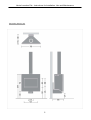
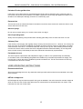
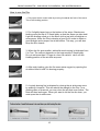
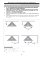
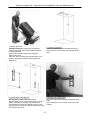
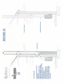
Harrie Leenders Dia Instructions for Installation, Use and Maintenance INSTRUCTIONS FOR INSTALLATION, USE AND MAINTENANCE DIA 1 Harrie Leenders Dia Instructions for Installation, Use and Maintenance IDENTIFICATION PLATE 2 Harrie Leenders Dia Instructions for Installation, Use and Maintenance General instructions and regulations Maintenance ………………………………………………………….. Service ………………………………………………………………… Declaration ……………………………………………………………. Characteristics report ………………………………………………... Description of the Dia ………………………………………...……… HETAS supplement Health and Safety precautions …………..…………………………. Chimney ……………………………………………………………….. Hearth …………………………………………………………………. Combustion air supply ……………………………………………….. Connection to chimney …………………………………………….... Commissioning and handover ……………………………………… Manual What you should know about the Dia …………………………..…. The three basic rules for proper burning ………………………….. Warning note …………………………………………………………. Important notes ………………………………………………………. User operating instructions …………………………………………. The fine heat from wood …………………………………………….. Initial fireup, a good start …………………………………………… Initial fireup in steps …………………………………………………. How to use the Dia …………………………………………..………. The power of fire ……………………………………………………… A few tips ……………………………………………………………… Maintenance Ceramic firebricks ……………………………………………………. Glass ………………………………………………………………….. Moving parts ………………………………………………………….. Collecting soot when sweeping the chimney ……………………… Installation instructions Dia specifications ……………………………………..……………… General instructions and regulations ………………………………. Safety recommendations ……………………………………………. Materials and tools required ………………………………………… Installation diagrams ………………………………………………… 3 6 6 6 6 6 7 8 9 9 9 9 10 10 11 11 12 13 13 14 15 16 16 17 17 17 18 19 20 20 20 21 / 24 Harrie Leenders Dia Instructions for Installation, Use and Maintenance 1. 2. 3. 4. 5. 6. 7. 8. 9. Door Ceramic Glass Aeration Slide Closing Convection slots Back casing Wall Bracket Refractory Baffle Steel Baffle 4 Harrie Leenders Dia Instructions for Installation, Use and Maintenance Connection sizes in mm 5 Harrie Leenders Dia Instructions for Installation, Use and Maintenance General instructions and regulations Maintenance Have the appliance serviced regularly by a qualified technician. Ensure that the fluegas connection and the chimney are cleaned regularly. Check to ensure that the chimney is still open before lighting the stove again if it has not been used for an extended period of time. If, in spite of the precautions taken, there should occur a chimney fire (usually accompanied by a roaring noise in the chimney), proceed as follows: Shut off the air supply and close the door of the stove immediately Call the fire brigade Quickly extinguish the fire in the stove with sand to prevent smoke from getting into your house Ventilate the house Never use water to extinguish the fire Ensure that after a fire the chimney is first swept and inspected for any damage and leaks. Service It is not allowed to make any modifications to the appliance without prior authorization of the manufacturer. Only use replacement parts recommended by the manufacturer. Declaration The undersigned, representing the following: Harrie Leenders Haardkachels, Industrieweg 25, 5688 DP, Oirschot, Nederland herewith declare that the product Dia is in conformity with the provisions of the following EC Directives when installed in accordance with the installation instructions contained in the product documentation: EN 13240:2001/A2:2004 (E) "Roomheaters fired by solid fuel" Product: Roomheaters fired by solid fuels as covered under the scope of this standard intended use: Space heating in residential buildings. Characteristics Report Fire safety Emission of combustion products Release of dangerous substance Surface temperature Mechanical resistance (to carry a chimney / flue) Thermal output / energy efficiency 2005PMC/12 2005PMC/12 2005PMC/12 2005PMC/12 2005PMC/12 2005PMC/12 Description of the room heater Dia: Wood stove made of sheet metal. The stove is designed to be installed on the wall. It is provided with a selfclosing window door, fixed secondary air supply and controllable air wash air supply. The combustion chamber is insulated with refractory ceramic elements. The fluegas connection is located at the top of the appliance. Notified body: Report number: Manufacturer: SGS Environmental Services, Postbus 5252, 6802 EG Arnhem 2005PMC/12 Harrie Leenders Haardkachels Name: Bart Leenders Position: General Manager Date: 15072005 6 Harrie Leenders Dia Instructions for Installation, Use and Maintenance READ THE INSTRUCTION BOOKLET AND THESE SUPPLEMENTARY INSTRUCTIONS CAREFULLY BEFORE INSTALLATION These instructions together with those in the instruction booklet cover the basic principles to ensure the satisfactory installation of the stove, although detail may need slight modification to suit particular local site conditions. In all cases the installation must comply with current Building Regulations, Local Authority Byelaws and other specifications or regulations as they affect the installation of the stove. It should be noted that the Building Regulations requirements may be met by adopting the relevant recommendations given in British Standards BS 8303, BS EN 152871:2007 as an alternative means to achieve an equivalent level of performance to that obtained following the guidance given in Approved Document J. Please note that it is a legal requirement under England and Wales Building Regulations that the installation of the stove is either carried out under Local Authority Building Control approval or is installed by a Competent Person registered with a Government approved Competent Persons Scheme. HETAS Ltd operate such a Scheme and a listing of their Registered Competent Persons can be found on their website at www.hetas.co.uk. CO Alarms: Building regulations require that when ever a new or replacement fixed solid fuel or wood/ biomass appliance is installed in a dwelling a carbon monoxide alarm must be fitted in the same room as the appliance. Further guidance on the installation of the carbon monoxide alarm is available in BS EN 50292:2002 and from the alarm manufacturer’s instructions. Provision of an alarm must not be considered a substitute for either installing the appliance correctly or ensuring regular servicing and maintenance of the appliance and chimney system. HEALTH AND SAFETY PRECAUTIONS Special care must be taken when installing the stove such that the requirements of the Health and Safety at Work Act are met. Handling Adequate facilities must be available for loading, unloading and site handling. Fire Cement Some types of fire cement are caustic and should not be allowed to come into contact with the skin. In case of contact wash immediately with plenty of water. Asbestos This stove contains no asbestos. If there is a possibility of disturbing any asbestos in the course of installa tion then please seek specialist guidance and use appropriate protective equipment. Metal Parts When installing or servicing this stove care should be taken to avoid the possibility of personal injury. STOVE PERFORMANCE Please refer to the table in the main instruction manual for details of the stoves’ performances 7 Harrie Leenders Dia Instructions for Installation, Use and Maintenance PREPARATORY WORK AND SAFETY CHECKS IMPORTANT WARNING This stove must not be installed into a chimney that serves any other heating appliance. There must not be an extractor fan fitted in the same room as the stove as this can cause the stove to emit fumes into the room. Chimney In order for the stove to perform satisfactorily the chimney height must be sufficient to ensure an adequate draught of approximately 15 Pa so as to clear the products of combustion and prevent smoke problems into the room. NOTE: A chimney height of not less than 4.5 metres measured vertically from the outlet of the stove to the top of the chimney should be satisfactory. Alternatively the calculation procedure given in EN 133841 may be used as the basis for deciding whether a particular chimney design will provide sufficient draught. The outlet from the chimney should be above the roof of the building in accordance with the provisions of Building Regulations Approved Document J. If installation is into an existing chimney then it must be sound and have no cracks or other faults which might allow fumes into the house. Older properties, especially, may have chimney faults or the cross sec tion may be too large i.e. more than 230 mm x 230 mm. Remedial action should be taken, if required, seek ing expert advice, if necessary. If it is found necessary to line the chimney then a flue liner suitable for solid fuel must be used in accordance with Building Regulations Approved Document J. Any existing chimney must be clear of obstruction and have been swept clean immediately before installa tion of the stove. If the stove is fitted in place of an open fire then the chimney should be swept one month after installation to clear any soot falls which may have occurred due to the difference in combustion be tween the stove and the open fire. If there is no existing chimney then any new system must be to the designation described above and in ac cordance with Building Regulations Approved Document J. A single wall metal fluepipe is suitable for connecting the stove to the chimney but is not suitable for use as the complete chimney. The chimney and connecting fluepipe must have a minimum diameter of 150 mm and its dimension should be not less than the size of the outlet socket of the stove. Any bend in the chimney or connecting fluepipe should not exceed 45°. 90° bends should not be used. Combustible material should not be located where the heat dissipating through the walls of fireplaces or flues could ignite it. Therefore when installing the stove in the presence of combustible materials due ac count must be taken of the guidance on the separation of combustible material given in Building Regula tions Approved Document J and also in these stove instructions. If it is found that there is excessive draught in the chimney then a draught stabiliser should be fitted. Fitting of a draught stabiliser will affect the requirement for the permanent air supply into the room in which the stove is fitted in accordance with Approved Document J (see also combustion air supply). Adequate provision e.g. easily accessible soot door or doors must be provided for sweeping the chimney and connecting fluepipe where it is not intended for the chimney to be swept through the appliance. 8 Harrie Leenders Dia Instructions for Installation, Use and Maintenance Hearth The hearth should be able to accommodate the weight of the stove and its chimney if the chimney is not independently supported. The weight of the stove is indicated in the brochure. The stove should preferably be installed on a noncombustible hearth of a size and construction that is in accordance with the provisions of the current Building Regulations Approved Document J. The clearance distances to combustible material beneath, surrounding or upon the hearth and walls adja cent to the hearth should comply with the guidance on the separation of combustible material given in Building Regulations Approved Document J and also in these stove instructions. If the stove is to be installed on a combustible floor surface, it must be covered with a noncombustible ma terial at least 12mm thick, in accordance with Building Regulations Approved Document J, to a distance of 30 cm in front of the stove and 15 cm to each side measuring from the door of the combustion chamber. Combustion air supply In order for the stove to perform efficiently and safely there must be an adequate air supply into the room in which the stove is installed to provide combustion air. The provision of air supply to the stove must be in accordance with current Building Regulations Approved Document J. An opening window is not appropriate for this purpose. Connection to chimney Stoves may have a choice of either a rear or top flue gas connector that allows connection to either a ma sonry chimney or a prefabricated factory made insulated metal chimney in accordance with their instruc tions. In some cases it may be necessary to fit an adaptor to increase the diameter of the flue to the mini mum required 150 mm section of the chimney or liner. Commissioning and handover Ensure all parts are fitted in accordance with the instructions. On completion of the installation allow a suitable period of time for any fire cement and mortar to dry out, before lighting the stove. Once the stove is under fire check all seals for soundness and check that the flue is functioning correctly and that all products of combustion are vented safely to atmosphere via the chimney terminal. On completion of the installation and commissioning ensure that the operating instructions for the stove are left with the customer. Ensure to advise the customer on the correct use of the appliance and warn them to use only the recommended fuel for the stove. Advise the user what to do should smoke or fumes be emitted from the stove. The customer should be warned to use a fireguard to BS 8423:2002 (Replaces BS 6539) in the presence of children, aged and/or infirm persons. 9 Harrie Leenders Dia Instructions for Installation, Use and Maintenance Manual We congratulate you on the purchase of your stove. This manual will inform you about the best way of using the stove and the art of keeping a perfect fire. Before using the stove, carefully read the text about breaking in the stove. These heating instructions apply to the Dia. They are merely intended as a guideline as your stove will behave differently according to the place where it is installed, simply because the conditions are different. The flue, the weather, the quality of the wood used and the climate conditions in the house determine your stove's burning behaviour. In time you will develop your own directions for use, based on these heating instructions. What you should know about the Dia The Dia is a radiant fireplace with a convection back plate which, when the fireplace is burning properly, ensures a fine heat distribution. The burning chamber is lined inside with highgrade ceramic firebrick elements (prisolith). These bricks are subject to the greatest impacts (being hit by wood when loading the fireplace) and so have been additionally reinforced. The air control slide controls the primary air flow over the fire and keeps the glass clean from above when used properly. The air control slide is opened by pulling it outwards. This is only the kindling position. The three basic rules for proper burning are: 1 Use dry and clean wood. The stove is suitable for burning socalled 'stackable fuels': wood and briquettes. We assume you will be using dry fuels only. So, this also holds for the kindling paper and cardboard. Wet fuel costs more energy, leaves moisture on the glass and soils the flue. 2 Do not temper the burning process excessively. Allow the stove sufficient time to warm up (stay with it at this stage) and do not temper the fire too quickly. Bear this rule in mind: you must not temper a stove until it has warmed up properly. 3 Always make sure there is enough fresh air. In houses today, cracks and chinks have often been sealed. Opening a small grate or cantilever window will ensure sufficient fresh air, provided no freshairsupply system is used. The main thing when making the fire is that both the flue and the stove reach the proper temperature. 10 Harrie Leenders Dia Instructions for Installation, Use and Maintenance READ THE INSTRUCTION BOOK AND THESE INSTRUCTIONS CAREFULLY BEFORE USING THE STOVE WARNING NOTE Properly installed, operated and maintained this stove will not emit fumes into the dwelling. Occasional fumes from de‑ashing and re‑fuelling may occur. However, persistent fume emission is potentially dangerous and must not be tolerated. If fume emission does persist, then the following immediate action should be taken:‑ (a) Open doors and windows to ventilate the room and then leave the premises. (b) Let the fire go out. (c) Check for flue or chimney blockage and clean if required (d) Do not attempt to relight the fire until the cause of the fume emission has been identified and corrected. If necessary seek expert advice. The most common cause of fume emission is flueway or chimney blockage. For your own safety these must be kept clean at all times. IMPORTANT NOTES General Before lighting the stove check with the installer that the installation work and commissioning checks de scribed above have been carried out correctly and that the chimney has been swept clean, is sound and free from any obstructions. As part of the stoves’ commissioning and handover the installer should have shown you how to operate the stove correctly. CO Alarm Your installer should have fitted a CO alarm in the same room as the appliance. If the alarm sounds unex pectedly, follow the instructions given under “Warning Note” above. Use of fireguard When using the stove in situations where children, aged and/or infirm persons are present a fireguard must be used to prevent accidental contact with the stove. The fireguard should be manufactured in accordance with BS 8423:2002 (Replaces BS 6539). Chimney cleaning The chimney should be swept at least twice a year. It is important that the flue connection and chimney are swept prior to lighting up after a prolonged shutdown period. If the stove is fitted in place of an open fire then the chimney will require sweeping after a month of continuous operation. This is a precaution to ensure that any “softer” deposits left from the open fire usage have not been loosened by the higher flue temperatures generated by the closed stove. In situations where it is not possible to sweep through the stove the installer will have provided alternative means, such as a soot door. After sweeping the chimney the stove flue outlet and the flue pipe connecting the stove to the chimney must be cleaned with a flue brush. 11 Harrie Leenders Dia Instructions for Installation, Use and Maintenance Periods of Prolonged NonUse If the stove is to be left unused for a prolonged period of time then it should be given a thorough clean to remove ash and unburned fuel residues. To enable a good flow of air through the appliance to reduce con densation and subsequent damage, leave the air controls fully open. Extractor fan There must not be an extractor fan fitted in the same room as the stove as this can cause the stove to emit smoke and fumes into the room. Aerosol sprays Do not use an aerosol spray on or near the stove when it is alight. Use of operating tools Always use the operating tools provided when handling parts likely to be hot when the stove is in use. Chimney Fires If the chimney is thoroughly and regularly swept, chimney fires should not occur. However, if a chimney fire does occur turn off the stove immediately and isolate the mains electricity supply (if applicable), and tightly close the doors of the stove. This should cause the chimney fire to go out. If the chimney fire does not go out when the above action is taken then the fire brigade should be called immediately. Do not relight the stove until the chimney and flueways have been cleaned and examined by a professional. Permanent air vent The stove requires a permanent and adequate air supply in order for it to operate safely and efficiently. In accordance with current Building Regulations the installer may have fitted a permanent air supply vent into the room in which the stove is installed to provide combustion air. This air vent should not under any circumstances be shut off or sealed. USER OPERATING INSTRUCTIONS Recommended fuels Stoves may be designed to burn dry seasoned wood logs and/or solid mineral fuel as indicated in the main stove manuals. HETAS Ltd Approval HETAS approval may be limited to specific fuel types as detailed in the main instruction manuals. Approval does not cover the use of other fuels either alone or mixed with the recommended fuel, nor does it cover instructions for the use of other fuels. 12 Harrie Leenders Dia Instructions for Installation, Use and Maintenance Initial fireup, a good start You have purchased a brandnew stove, 'zero on the meter', has not seen a flame yet. This means you are going to take care of the initial 'miles'. The ceramic firebricks will start evaporating moisture and your woodburning stove will start setting. For this reason, the first few times, do not make your fire too hot because otherwise the bricks could crack. You need not worry about any shrinkage cracks. The initial fireup requires some additional time and attention, as well as the approach we have outlined below for you in steps. Before starting, please note the following important points: When starting the fire in the stove, open the aeration slide. (This is the kindling position.) You can properly control the fire with the aeration slide. The further the slide is opened, the more vigorously your fire will burn. Make sure there is sufficient ventilation. 13 Harrie Leenders Dia Instructions for Installation, Use and Maintenance Initial fireup in steps 1. Open the air slide completely by pulling it towards the front of the stove. This is the kindling position. 2. Light a large ball of dry paper against the back plate of the burning chamber and allow this fire to go out again. 3. Fill the stove with a handful of dry and thin kindling wood and light it. When it burns properly, close the air slide a bit by pushing it inwards. 4. Allow the fire to burn up and the stove to cool off for an hour so that the moisture in the firebrick can evaporate. Some liquid might come free from the ceramic firebrick. Therefore place an old towel underneath the stove before firingup 5. After an hour, you will start bringing the entire stove to the proper temperature using first some thin kindling wood. Use the kindling position of the air slide until the fire burns properly. 6. Then use thicker logs, ± 5x5 cm thick and 20 cm long. At the same time, leave the aeration slide open. Close it a little bit when the fire is burning properly. 14 Harrie Leenders Dia Instructions for Installation, Use and Maintenance How to use the Dia 1. Fully open the aircontrol slide by moving it towards the front of the stove. This is the kindling position. 2. Put 2 slightly larger logs on the bottom of the stove. Stack some kindling wood on top of it. Stack lightly so that the flame can take hold. Light the kindling wood up in the stove (at the top) with a firelighter or some paper. Allow the Dia to develop a good fire in order to obtain a good draught and a proper fire at the bottom. This way, you will also keep the flue cleaner. 3. When the fire gets smaller, add solid wood varying in thickness from 5 to 7cm. The amount depends on the heat required. Stack lightly. Do not add more than 2.5 logs at a time. Be careful, don't use the kindling position of the air slide anymore. 4. After each loading, give the fire some extra oxygen by opening the air slide a little bit until it is burning properly. 5. A quietly burning fire is obtained by closing the air slide even more by pushing it inwards. This will reduce the draught in the Dia. For a glowing mass of charcoal, you may close the air slide even further. The heat will then last longer. When you want to let the fire die down, you must open the air slide more. 15 Harrie Leenders Dia Instructions for Installation, Use and Maintenance The power of fire As a matter of fact just a few things withstand a real hot fire. Your fireplace can also be damaged by overheating. Just to prevent this, take account of not burning more than 3,5 kilograms of wood at the same time. 3,5 Kilograms is approximately equal to 3,5 large logs; oak with 15% moisture. The construction and the materials used from the fireplace are chosen to control and resist a fire in a considered way. So heat with consideration. A few tips Make the fire always on a bed of ash. This is an insulating layer for the fire and an excellent bed for the fuel. If the Dia is overloaded with too much wood and the maximum amount of oxygen is sup plied (which happens when the air slide is fully open), the fire may 'run wild'. If this should occur, close air slide by pushing it inwards. Never in such case leave the fireplace unat tended. You also control the temperature by the amount and kind of fuel used for each load. Remove excess ashes using a shovel or an ash cleaner. Never remove ashes using a vacuum cleaner because fire may still continue to smoulder for days. Make sure you leave a layer of ashes (± 3 cm) for the next fire to be made. When the weather is foggy, preheat the flue prior to lighting your fire.. 16 Harrie Leenders Dia Instructions for Installation, Use and Maintenance Maintenance Maintenance Maintenance 1. Dust the stove using a nonfibrous cloth. 2. Damaged spots can be touched up using an abrasive cloth and Harrie Leenders stove paint. Ask you supplier for advice Maintenance ceramic firebricks You need not worry about any cracks in the ceramic firebrick elements as long as the flame does not come into direct contact with the metal behind them. Glass The glass can steam up when burning wet fuel or too little oxygen is supplied. Also, the glass may steam up if the fire does not start fiercely enough. This happens, for instance, when you start with small logs instead of thin kindling wood. Moisture will then remain in the fireplace for too long, and will settle on the coldest part: the glass. Light moisture: Use paper towel and then remove the light moisture using a damp cloth. Counter pressure a little at the outside so that the glass panel does not move. Thicker deposits: These can be treated with special fireplace glass cleaner (this can also be done with a piece of moist paper towel and white ash). Allow a moment for this to have its effect. Always make sure that these agents do not come into contact with the painted surfaces in order to prevent stains from being formed. Moving parts Moving and squeaking parts can be lubricated using graphite grease. Ask your supplier for advice. 17 Harrie Leenders Dia Instructions for Installation, Use and Maintenance Collecting soot when sweeping the chimney The refractoryboard baffle and steel baffle must be removed so that the soot being removed during chimney sweeping will land at the bottom of the stove. 1. Slightly lift the ceramic baffle and pull it towards you. You can then take it out easily. Then lift the steel baffle to remove it. 2. Place a newspaper on the bottom of the stove to collect the accumulated soot. Close the door and the aircontrol slide. After sweeping the chimney, remove the accumulated soot from the stove and put the refractory baffle and the steel baffle back in their respective positions. 18 Harrie Leenders Dia Instructions for Installation, Use and Maintenance Installation instructions · · · · · All local regulations including those referring to national and European standards must be observed when installing the appliance. Ensure there is sufficient ventilation / air supply in the room from which your stove gets the combustion air. This is the room where the stove is installed if you do not use a wall or stovebase airsupply system. The stove is not suitable for a shared flue system. Ensure adequate access for cleaning the appliance, the flue gas connection and the chimney. When installing the stove, take into account the minimum distances from the wall so as to avoid any fire risk. The minimum distances (sizes in cm) are shown in the figure below. Specifications Dia Nominal power of the stove is 5.4 kW. Flue gas mass flow = 5.3 g/s Appliance weight = 95 kg Minimum chimney draught = 8.0 Pa Flue gas temperature directly over the stove = 357 °C 19 Harrie Leenders Dia Instructions for Installation, Use and Maintenance General instructions and regulations The installation of the Dia with decorative casing must be carried out by a skilled per son employed by a dealer recognized by Harrie Leenders Haardkachels. The casing parts are susceptible to scratching. Handle them gently. After the stove has been properly installed, burn some kindling wood to check the draught. Please Note, the Dia has been tested by the manufacturers on a 3m straight flue. Safety recommendations Glass tends to break easily, and broken glass is quite sharp. Therefore take adequate safety precautions. For general safety, we refer to guidelines or regulations issued by a relevant official body Materials and tools required · · · · · · · · · · Crosshead screwdriver Box spanner set Hexagonal wrench set Masonry bits Knife Plumb line Sliding pieces Spirit level Sack truck Single walled flue pipe and accessories Materials included · · · Top plate with or without a hole for top or rear outlet Right angled bend ( rear outlet only ) 4 self tapping screws 3.5 x 9.5 ( +2 spares ) TIP. Corner brackets can be ordered for inside and outside corners 20 Harrie Leenders Dia Instructions for Installation, Use and Maintenance 1. Moving the stove Carefully remove the casing from the stove by moving it upwards; leave the packaging material covering the stove. Unscrew the transport brace from the pallet. Remove the bolts. Place the stove including the transport brace on a sack truck (the stove's back resting against the sack truck). 2. Centre of connection Take the centre line for the wall bracket as pro jected from the centre of the flue (using a plumb line). 3. Positioning the wall bracket Determine the centre of the wall bracket. Drill the upper hole at 712mm from the floor using a Ø 6mm masonry bit. Use the wall bracket as a template and a spirit level to drill the other 5 holes using a Ø 6mm masonry bit. Ream the 6 holes using a Ø 14mm masonry bit. 4. Mounting the wall bracket Mount the wall bracket using the expansionshell bolts. Affix 2x flat tape on the vertical strips of the wall bracket. 21 Harrie Leenders Dia Instructions for Installation, Use and Maintenance 5. Hanging the stove Place sliding pieces underneath the transport brace. Push the stove against the wall bracket so that the oblong holes slide over the eyes. Be careful not to damage the floor. Place the 2 pins into the eyes with the opening 6. Removing the transport brace Remove the 4 bolts from the transport brace using a spanner. Remove both legs from the transport brace. 7. Levelling the stove Use the 2 MIO sockethead bolts provided on the underside of the wall bracket to level the stove width wise (sockethead wrench 5). 8. Levelling the stove Use the 2 M8 sockethead bolts provided at the back of the wall support to level the stove depth wise (sockethead wrench 4). Tap the pins into place. 22 Harrie Leenders Dia Instructions for Installation, Use and Maintenance 9. Fitting wallsupport finishing cover Fit the finishing cover by sliding the projections into the slots. If the cover is not fixed properly, use the 2 M8 bolts from the transport brace to fix the cover. 10. Placing the casing Take the casing out of the packaging material. Open the door of the stove. Carefully put the casing over the stove sliding it, without damaging the paint, until touching the stop. 11. Installing flue Place the pipe on the rotating collar at the top of the stove. Check the connection. 12. Rotatable? Fixed position: leave bolts in place as delivered. 2 x 45° rotatable: remove bolts no. 1 then release bolt no. 2 and secure it with the nut. 23 Harrie Leenders Dia Instructions for Installation, Use and Maintenance 13. Service: adjusting the door Remove the pipe and casing from the stove. Open the door. Adjust the door so that it hangs parallel using an openend 10mm spanner 24 Harrie Leenders Dia Instructions for Installation, Use and Maintenance 25 Harrie Leenders Dia Instructions for Installation, Use and Maintenance U K Distributor. Robeys Ltd. Riverside, Goods Road, Belper, Derbyshire, England. DE56 1UU Tel: 01773 820940 Fax: 01773 820477 E Mail: [email protected] www.robeys.co.uk 26 June 2011