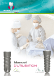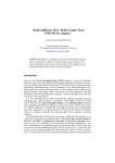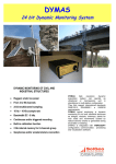
1
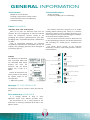
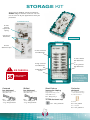
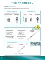
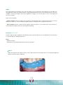
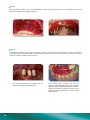
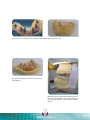
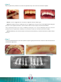
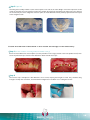
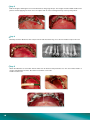
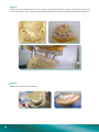
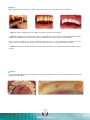
ALL BAR
IN
User’s
GUIDE
Surgery & Prosthesis
®
Introduction
euroteknika is the result of 22 years of clinical applications and 26 years of research and development
confirmed by valuable help of international research laboratories.
The design of our implants is based on the skills of our teams wich are both reactive and experienced in implantology:
Technical and biomechanical skills of our engineers enabling to guarantee the resistance of the component and
their adaptation to the oral environment thanks to modern means of simulation.
Biological and physiological skills of the associated laboratories enabling to validate the capacity of
osseointegration of our systems.
Clinical and practical skills of our dentists advisers ensuring the ergonomics of our products, the confirmation of
our protocols and the ranges adapted to the various clinical cases.
To enable you to take the best advantage of the bar abutments, we created this manual with a profesionnal care. We
invite you to read it with your best attention. Each detail, even the least important, has its importance and underlines
even more the difference between the beginner and the specialist.
2
CONTENTS
Warning
p. 3
General information
p. 5
Bar abutments
p. 6
Storage kit
p. 7
Protocol
p. 8 to 16
IMPRESSION TAKING
MATERIAL REQUIRED
USE
Indirect method
Direct method
P.
P.
P.
P.
P.
8
8
9
9
14
For more information on the ALLINBAR® system,
please visit our complete internet website,
www.euroteknika-implants.com
3
Warning
The placement ot bar abutments must be done by a practioner who has been previously trained for the dental
implantology techniques and in aseptic conditions specific to this type of treatment.
The following instructions will guide you throughout the different stages of your implantology treatments. They
contain advice as precise as possible but cannot be used as «recipes», every clinical situation must be evaluated
for each patient. A great number of factors acts independently to obtain success in an implantology treatment. It
is up to the practioner to recognize the key factors and to use his clinical experience. Among other aspects, the
coordination between the prosthesis laboratory dental technician and the practioner must be perfect so as to give
the global treatment plan more consisting. Only the practioner remains responsible for his different choices and
decisions as to the treatment’s feasibility, implants, prosthetic parts, materials used and settings... The technical
specifications and clinical advice in this manual are given solely as a guideline and cannot give rise to any claims.
All the essential information is indicated in the instruction for use supplied with products.
We have taken great care in the design and production of our products. However, we reserve the right to bring
modifications or improvements arising from new technical developments in our implantology system.We will advise
of any modifications having an implication in the operation mode. According to the importance of the modifications,
a new manual will be issued. Indeed, a mark on the back page indicates the date of issue of your surgery manual,
and enables us to check if you have the latest up date version. You will also be able to access our web site to check
the latest version of this manual.
The reproduction and distribution of all or part of this manual need previous agreement from euroteknika.
4
GENERAL INFORMATION
Instructions
Contraindications
Multiple or total restoration
Creating a rigid structure similar to a bar
Limited execution time in the laboratory
Immediate loading
Single restoration
Low primary stability (when used directly)
Parts PACKAGING
Sterility and rule of asepsis
Most of our parts are delivered sterile and can
therefore be used straightaway. A reference indicator
shows the components effective sterility on the
packaging. The sterility is guaranteed for 5 years (from
packaging date). A standard expiry date is indicated on
the label.
Only an undamaged packaging can guarantee
the products imperviousness and sterility. Do not use
implants with packaging which has been damaged or
prematurely opened.
Labels
Our abutments are delivered
with 2 principal labels and
one removable label clearly
showing the mark, the
reference and the batch
number (for a total of 3
labels):
Our products have been designed so as to enable
handling without affecting their sterility. It is therefore
important to follow a precise handling technique so as
not to compromise the conventionnal hygiene conditions
associated with the implant practice.
The non sterile instruments and items delivered used
for the implantology treatment must be decontaminated
and, according to a tested process, sterilized at the
practice.
The plastic pieces (except for the occlusion
abutments) cannot be sterilised by autoclave. Choose
cold sterilisation.
Manufacturing
!
Be careful see delailed description
Date of manufacturing
Pilier-bar
ARS_PT_AC
2 labels for the patient’s file
of the practioner who placed
the implant and/or of the
correspondent.
1 label for the patient.
Store in a dark place
Store in a dry place
Compling with European requirements directives
regarding medical plan 93/42 CEE
Use until
Don’t use if the packing is damaged
See the instruction manual
Sanitation method using radiation
Product reference number
Serial number
Don’t reuse
Don’t sterilize twice
Storage OF THE PRODUCTS
The abutments must be stored in a clean, dry and cool
place.
Precautionary MEASURES
It is strongly advised to keep in stock
abutments which cover different possible cases.
We recommend to use a safety thread on the
instruments to avoid any accidental fall of tools in the
patient’s throat.
5
BAR ABUTMENTS
Description AND INFORMATION
Bar abutments are designed to build a passive bar without using traditional methods.
The flexibility of these abutments, and the fact that they are glued together by adding resin make it easy to build a
framework.
This prosthetic construction may be performed in the mouth (direct method), or in the laboratory, after taking an
impression (indirect method).
This is why the bar abutment has the following characteristics:
Abutment with flexible winglets available in two versions (shifted and centered), and in two lengths
Sandblasted abutment that enables the resin to stick
Winglet bodies are flexible on the horizontal axis, making them more malleable
Abutment can be used on Tetra abutments (straight or angular), available in the following ranges: Naturactis,
Natea+, Naturall+, and Uneva(+)
2 horizontally flexible wings and vertically very rigid. The
horizontal flexibility allows them to be easily bent in order to
fit the patient’s arch anatomy.
Possibility to touch up the wings
by cutting them in the height
and/or width
Asperities
(holes and irregularities)
allowing the resin to infiltrate in
the wings
Sandblasted abutment in
order to allow the resin to
have a good grip
Goes onto the TETRA abutments
of our ranges of implants
CENTERED WINGS ABUTMENT
With a slight shift for the wings’
overlapping between abutments
SHIFTED WINGS ABUTMENT
For cases when the implant is
perfectly in the teeth axis
For cases when the implant is not
centered in the teeth axis
6
Axis
difference
STORAGE KIT
All the tools for building a fixed resin/titanium
ALLINBAR® bridge fit into this small case. You can
use the case for all your appointments with your
prosthetist.
SUPERIOR PLATE
8 short
pick-up
impression
coping
8 occlusion
abutments
Ref. : ARSK_74
LOWER PLATE
8 Tetra
abutment caps
8 short centered
bar-abutments
4 short shifted
bar-abutments
2 long centered
bar-abutments
!
134°c
BE CAREFUL
2 long shifted
bar-abutments
16 bar-abutment
screws
DO NOT STERILIZE
BY AUTOCLAVE
Centered
bar-abutment
Supplied with fixing screw
UPV_VMD.14.38
Shifted
bar-abutment
Supplied with fixing screw
UPV_VMD.14.38
1 housing by
component to make
easier the component
re-supplying
Short Pick-up
impression coping
Set of 4 parts
Supplied with fixing screws
UPV_VGM.14.100
Occlusion
abutment
For occlusion registration
on Tetra abutments using
the indirect method.
Ref. : ARS_TT.74_4
Ref. :
- short : ARS_PT.AC
- long : ARS_PT.AC.30
Ref. :
- short : ARS_PT.AT
- long : ARS_PT.AT.30
TETRA abutment cap
Ref. : UPV_CPT48.20
Sold unit
Ref. : UPV_PO.48
Set of 10 parts
Ref. : UPV_PO.48.10
7
THE PROTOCOL
Possible IMPRESSIONS
An impression will only be taken if the construction is performed indirectly, in the laboratory. This is a traditional
impression process on Tetra abutments. However, specific transfers are used.
SHORT PICK-UP IMPRESSION
(for impressions through a splint)
By using short pick-up transfers, an impression
with a verification of the occlusion can be made
Short pick-up impression
Tetra abutment
Supplied with a fixing screw
analog
UPV_VMD.14.100
Ref. : ARS_TT.74
Ref. : UPV HM 48
STANDARD IMPRESSION
(traditional method)
Pick-up
impression
coping
Ref. : UPV TM 48
or
Pop-in
impression
coping
Tetra abutment
analog
Ref. : UPV PI 48
Ref. : UPV HM 48
Material required FOR USING BAR ABUTMENTS
FOR SETTING TETRA ABUTMENTS
Internal hexagonal key
External hexagonal key
Ref. : CCL_HI20.24
Ref. : CCL_HE12.XX
Internal hexagonal mandrel
External hexagonal mandrel
Ref. : UMA_HI20.26
Ref. : CMA_HE12.XX
FOR USING BAR ABUTMENTS
External hexagonal key
Torque wrench
for prosthesis
Ref. : CCL_HE12.XX
Ref. : CCC_35
8
Torque wrench
for prosthesis
Ref. : CCC_35
USE
This protocol details the utilization steps, after the implants are set, and after the Tetra abutments are installed. The
Tetra abutments match the solutions that the company Euroteknika offers for trans-screwed prostheses. They are
available in various gum heights, and in three angulations: straight (1, 2, 3, 4 mm high), 17° (2, 3, 4 mm high), and
30° (3, 4 mm high).
There are two methods:
Indirect method: the bar is fitted and put together in the laboratory after a specific impression on the Tetra
abutments is taken. It is recommended for implants that have already become integrated into the bone.
Direct method: the bar is made and put together while the patient is in the dental chair. This technique is
recommended for implants that are to be installed immediately.
Indirect METHOD
The bar is adjusted and put together in the laboratory after a specific impression on Tetra abutments. This technique
is recommended for immediate placement.
Pros
Quick and simple.
Adjustment of the abutment/bar by the prosthesis specialist.
Step 1
Before the extraction and implant insertion, create a bite mould of the remaining teeth or on a temporary bridge (the
patient’s occlusion must be stabilised).
9
Step 2
After installing the implants and the Tetra abutments, connect the pick-up transfers to the Tetra abutments. Take the
impression (implant site and opposing teeth).
Step 2
Tetra occlusion abutments have been developed in order to recover the occlusion registration. They are made from
sterilisable plastic by autoclaving and can be retouched. In order to be able to re-position them on the master model, a
flat plane has been created at the crown level.
The occlusion abutments are clipped onto the
straight or angulated Tetra abutments.
10
In the mouth and in occlusion, wax, resin, or
silicone is applied liberally between the occlusion
abutments and the opposing teeth (occlusion bite
mould). This makes it possible to record the exact
position of the Tetra abutments in relation to the
opposing teeth.
Once you have the mould, create a master model and the opposing plaster cast.
The occlusion abutments are then mounted onto
the analogues.
Mount the master model and the opposing plaster
cast onto the articulator. Then align according to
the occlusion abutments and the abutment bite
mould.
11
Step 4
Mount and shape the ALLINBAR® abutments.
Step 5
Create the resin bridge with commercial teeth.
12
Step 6
After reception of the prosthetic set, remove the protection caps. Then screw the set onto the implants.
Phase 1: screw in staggered rows on 3 points, to align the occlusion and the gum.
Phase 2: manually screw the remaining screws in staggered rows. Pressure must not be applied when fitting the
prosthesis to the implant connections. There must be a clear increase in torque, and it must be effortless.
Note: experiencing effort on the screws, or difficulty inserting the set is a sign of inadequate passiveness. This can
quickly result in an implant failure. Working on the prosthesis will thus be essential for permanent loading.
Phase 3: definitively screw with the torque wrench and the external hex key, or with the external hex mandrel. Torque:
20 N.cm.
Step 7
Use your method to block the screw wells (cotton or a point of gutta-percha must be used). Then make the final occlusal
and aesthetic adjustments.
13
Direct METHOD
The bar is made and put together in the dental chair. This technique is recommended for implants that are already
osseointegrated (but it can also be used for immediate loading).
Pros
Framework/beam is completely passive.
Cons
«Tedious» work in the dental chair.
Makes the «surgery» last even longer.
Making occlusal splints (optional for both methods)
With this technique, the occlusal splints can find the exact location of the future Tetra abutments with respect to
the antagonist teeth, after extraction/implantation. The impression is taken in the occlusal splint, on the bridge side.
Building these splints requires preliminary work.
Step 1 (optional)
Take a bite registration and an impression of the patient’s upper/lower jaws. Pour the plaster models and mount with an
articulator. Create occlusion splints on the plaster models (site to be restored and opposing dental arch). Fix the female
part of the occlusion pins to the opposing splint and the occlusion pins onto the splint of the arch to be restored.
Step 2 (optional)
Put the male ends of the occlusal pins in the female ends. Put the models in the articulator in occlusion. Connect the
male ends to the splint on the side of the future bridge. A positioning bar may be added in the front.
14
Step 3 (optional)
Checking the assembly. Hollow out the occlusal splint on the side of the future bridge so that the impression can be
made via short pick-ups in the splint (be careful not to weaken the splint). By repositioning the impression in this splint via
the 4 occlusion pins on the antagonist occlusion splint, the Tetra abutments will be perfectly repositioned with respect
to the antagonist teeth.
Create the titanium framework in the mouth and bridge in the laboratory.
Step 1 (For the creation of a bridge with immediate loading)
Screw the Tetra abutments on the implants (see the procedure in the surgery manual or the Tetra product sheet). Then
screw the protection caps onto the Tetra abutments. Stitch around these caps.
Step 2
Unscrew the caps and adjust the bar abutments one at a time, keeping their lengths in mind. They should be long
enough to overlap with each other, and should limit misalignment in the back. Use a cutting disc for this.
15
Step 3
Fold the winglets, following the curve of the dental arch, with gouge forceps. The winglets must be folded outside of the
patient’s mouth. Applying too much stress on implants that are not osseointegrated may result in primary failure.
Step 4
Manually screw the abutments with a torque wrench and external hex key, or use the hex mandrel. Torque: 20 N.cm.
Step 5
Attach the abutments to each other with the white resin for dentures that prosthetists use. This resin will be mixed in a
syringe, and applied to the holes. Be careful not to fill the screw wells.
A dam must be used.
16
Step 6
Install the occlusion splint around the framework that has already been built. Attach the occlusal splint to the framework
with dots of wax in the vestibule. Then register the occlusion of the antagonist teeth with respect to the ALLINBAR®
framework. After the occlusion is registered, remove the antagonist occlusal splint.
Step 7
Use high-resolution impression silicon to take the impression of the peri-implant gum. Then bind the framework to the
splint with traditional impression material. Keep access to the screw wells free.
Step 8
Unscrew the splint/framework ensemble, mount the analogues on the bar abutments and send to the laboratory. Fix the
protective caps onto the Tetra abutments.
17
Step 9
Create the master model. Mount the master model on the articulator and align using the opposing plaster cast, using
the occlusion splints. (This re-alignment could also potentially be done with the technique using occlusion abutments).
Step 10
Build dentures with resin in the laboratory.
18
Step 11
After reception of the prosthetic set, remove the protection caps. Then screw the set onto the implants.
Phase 1: screw in staggered rows on 3 points, to align the occlusion and the gum.
Phase 2: manually screw the remaining screws in staggered rows. Pressure must not be applied when fitting the
prosthesis to the implant connections. There must be a clear increase in torque, and it must be effortless.
Note: experiencing effort on the screws, or difficulty inserting the set is a sign of inadequate passiveness. This can
quickly result in an implant failure. Working on the prosthesis will thus be essential for permanent loading.
Phase 3: definitively screw with the torque wrench and the external hex key, or with the external hex mandrel. Torque:
20 N.cm.
Step 12
Use your method to block the screw wells (cotton or a point of gutta-percha must be used). Then make the final occlusal
and aesthetic adjustments.
19
A global solution FOR IMPLANTOLOGY
euroteknika groupe
726 rue du Général De Gaulle - 74700 SALLANCHES - France
Tél. : 33 (0)4 50 91 49 20 - Fax : 33 (0)4 50 91 98 66
www.euroteknika.com
MU_ALLINBAR.GB_1402