1
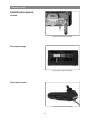
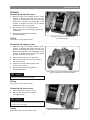
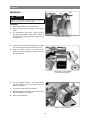
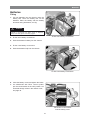
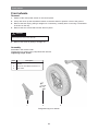
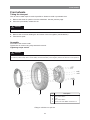
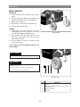
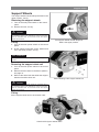
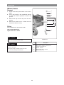
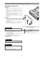
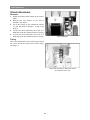
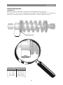
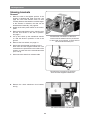
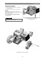
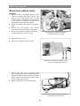
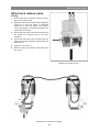
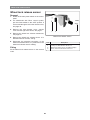
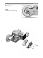
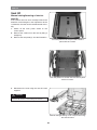
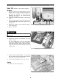
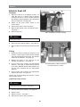
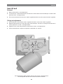
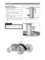
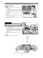
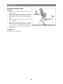
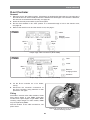
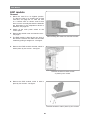
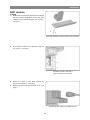
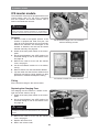
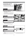
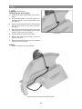
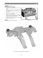
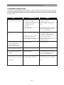
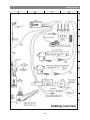
SERVICE MANUAL US Permobil C400 Power wheelchair Permobil C400 Order no.: 205225-US-0 How to contact Permobil Head Office of the Permobil group Produced and published by Permobil AB, Sweden Edition no.3, 2010-06 Order no.: 205225-US-0 Contents Contents Introduction ...................................................................................................... 5 Identification plates ......................................................................................... 6 Covers ............................................................................................................... 7 Batteries ............................................................................................................ 8 Front wheels ................................................................................................... 10 Rear wheels .................................................................................................... 12 Support wheels .............................................................................................. 13 Wheel forks ..................................................................................................... 14 Rear wheel suspension ................................................................................. 15 Shock absorbers ............................................................................................ 16 Slewing brackets ............................................................................................ 18 Wheel lock release cable ............................................................................. 20 Wheel lock release sensor ............................................................................ 22 Magnetic wheel lock ...................................................................................... 23 Drive motor ..................................................................................................... 26 Seat elevator ................................................................................................... 28 Fixed seat post ............................................................................................... 36 Adjusting the Seat Height ........................................................................... 36 Removal ...................................................................................................... 37 Control panel .................................................................................................. 38 R-net controller .............................................................................................. 39 ESP Module .................................................................................................... 40 ICS Master Module ......................................................................................... 42 Fuses ............................................................................................................... 42 Charging fuse . ............................................................................................ 42 Main Fuse ................................................................................................... 43 Lights .............................................................................................................. 44 Control System . ............................................................................................. 46 Trouble shooting ............................................................................................ 47 Cabling overview . .......................................................................................... 60 Index ................................................................................................................ 62 4 Introduction Introduction The Service Manual is intended for technical personnel who maintain and repair power wheelchairs. It is important that anyone who performs maintenance and repairs described in this manual reads and understands the content of this manual so that the work is performed professionally. Always state the chassis number when contacting Permobil to ensure that the correct information is provided. Technical Support In the event of technical problems, you should contact your dealer, or Permobil Inc. USA at 800-736-0925. Spare parts Spare parts must be ordered through your dealer. Warranties Contact your dealer or Permobil Inc. USA for information about the warranties for this chair. Maintenance See the information in the Owner’s Manual. 5 Identification plates Identification plates Chassis Chassis identification number. Rnet output stage Rnet output stage ID number Rnet control panel Control panel Rnet ID number 6 Identification plates Covers Removing the seat lift cover 1. Raise the seat to the highest position. If the chassis is equiped with fixed seat post, see page 36. If the seat lift does not work normally because the batteries are discharged or the actuator is defective, the seat can be raised/ lowered manually, see page 28. 2. The seat lift cover is mounted with four plastic plugs which can be flipped up using a screwdriver. 3. Remove the seat lift cover by lifting it upwards/forwards. The seat lift cover is mounted with four plastic plugs. Fitting Fit the cover in the reverse order. Removing the chassis cover 1. Raise the seat to the highest position. If the chassis is equiped with fixed seat post, see page 36. If the seat lift does not work normally because the batteries are discharged or the actuator is defective, the seat can be raised/ lowered manually, see page 28. 2. Remove the seat lift cover, see above. 3. Remove the two knobs on the front edge of the cover, see fig. 4. Unscrew the knob at the far back of the chassis cover, see fig. 5. Remove the chassis cover by lifting it upwards/backwards. m The chassis cover is mounted with two knobs at the front edge and a knob at the back. CAUTION If the chair is equipped with lighting, disconnect the rear-light cabling at the connector fitted on the cabling. Fitting Fit the cover in the reverse order. Removing the front fender 1. Remove the three screws, see fig. 2. Remove the front fender by lifting it upwards/forwards. m CAUTION If the chair is equipped with lighting, remove the chassisand seat lift cover. Disconnect the front-light cabling at the connector fitted on the cabling. Fitting The front fender is mounted with three screws. Fit the front fender in the reverse order. 7 Batteries Batteries m Off On Warning Be careful when using metal objects when working with batteries. A short-circuit can easily cause an explosion. Always use safety gloves and safety goggles. Removal 1. Place the wheelchair on a level surface. 2. Switch off the main power switch on the control panel. 3. On wheelchairs with Pilot+ control system, put the circuit breaker in the “OFF” position. It is accessed through a hole in the chassis cover; see page 43. Circuit breaker (Off/On). 4. Loosen the rear end of the chassis cover a little by unscrewing the knob that holds the cover. 5. Open the battery covers by loosening the knobs that holds the battery covers, and drop the covers down. The knobs on the chassisand the battery cover. 6. Use the battery straps to pull each battery out just enough so you can loosen the outer battery connection. 7. Loosen the outer battery connection. 8. Pull the batteries completely out and disconnect the inner battery connections. 9. Remove the batteries. Pulling out the batteries 8 Batteries Batteries Fitting 1. Lift new batteries into the chassis using the battery belt. Leave the battery belt on the batteries. Place the battery with the battery terminals facing backwards, see fig. m Warning Be careful when using metal objects when working with batteries. A short-circuit can easily cause an explosion. Always use safety gloves and safety goggles. Fit the inner battery connections. 2. Fit the inner battery connections. 3. Push the batteries halfway into the chassis. 4. Fit the outer battery connections. 5. Push the batteries fully into the chassis. Fit the outer battery connections. 6. Close the battery covers and tighten the knobs. 7. On wheelchairs with Pilot+ control system, put the circuit breaker in the “ON” position. It is accessed through a hole in the chassis cover; see page 43. The knobs on the chassisand the battery cover. 9 Front wheels Front wheels Removal 1. Switch off the main power switch on the control panel. 2. Lift up and chock up the wheelchair chassis so that the wheel in question is free of the ground. 3. Remove the hub cap by pulling it straight out. If necessary, carefully lever it out using a screwdriver in the slot on the cap. 4. Remove the four screws that hold the wheel in place. m Warning The central screw must not be removed. 5. Remove the wheel by pulling it straight out. Assembly Assemble in the reverse order. Tighten the four screws using a dynamometric wrench. Tightening torque 24 Nm. Item Description 1 Hub cap 3 Rear wheels 2 Screw, ISO 4762 M8x20 8.8 Fe/Zn 5 C1 1 2 3 Fitting/removing front wheels. 10 Front wheels Front wheels Taking the rim apart The rim can be taken apart to make it possible to fit/remove solid or pneumatic tires. 1. Remove the wheel in question from the wheelchair. See the previous page. 2. If the tire is pneumatic, release the air. m Warning Ensure that pneumatic tires are not pressurized before the rim is taken apart, otherwise there is a risk of personal injury. 3. Remove the six screws holding the two halves of the rim together (see illustration). 4. Take the rim apart. Assembly Assemble in the reverse order. Tighten the six screws using a dynamometric wrench. Tightening torque: 22 Nm. m Warning The recommended tire pressure for pneumatic tires is 200 kPa (2 bar). Overfilling entails a risk of explosion. Incorrect tire pressure may result in lower stability and maneuverability. Check regularly that the tires have the correct pressure. 4 3 1 Item 2 1 Rim, outer section 3 Rim, outer section 2 4 Fitting a solid tire to a split rim. 11 Description Tire Screw, ISO 4762 M8x30 8.8 Fe/Zn 5 C1 Rear wheels Rear wheels Removal 1. Turn off the main power switch on the control panel. 2. Lift the wheelchair chassis and support it on blocks so that the wheel is off the ground. 3. Remove the hucap (1). 4. Remove the screw (2) and the washer (3). 5. Pull the wheel off the shaft. Fitting 1. Check that the wheel shaft and rim are undamaged. Clean as necessary to remove dirt and rust. Replace damaged parts. Rear wheels 2. Fit the wheel onto the axle with the use of hand force only. Make sure the rim is fully seated upon the axle. 3. Fit the washer (3) onto the screw (2) and secure the wheel. Use a torque wrench to tighten the bolt to 17.7 ft-Ibs (24 Nm). m CAUTION Do not use a Pneumatic impact wrench. m WARNING The bolt must be used once only. Removed bolt is not allowed to be refitted. Other types of bolts or washers are not to be used. Do not use any other type of thread lock. 1 2 4 3 Fitting of rim. Pos. 1 Hubcap 3 Washer, 8.5x23x3 2 4 12 Description Bolt, ISO 4017 M8x16 8.8 Fe/Zn 5 C1 / Locking coat DIN 267-28 Rear heel Support wheels Support Wheels The support wheels should always be fitted in the upper position, see fig. Removing the support wheels 1. Turn off the main power switch on the control panel. 2. Remove the bolt, see fig. m WARNING Removing the support wheels entails an increased risk of the wheelchair tipping over. Wheelchairs with support wheels fitted as standard must not be driven when the support wheels are removed. The support wheels should always be fitted in the upper position. Fitting 1. Turn off the main power switch on the control panel. 2. Fit the support wheel with screw, washer and nut in the lower position, see fig. m OBSERVERA The support wheels should always be fitted in the upper position. Removing the support wheel unit 1. Turn off the main power switch on the control panel. 2. Remove the front wheel on the side in question, see page 10. 3. Remove the three bolts that holds the support wheel unit and the drive unit. m Removal/fitting of the support wheel unit. WARNING Removing the support wheels entails an increased risk of the wheelchair tipping over. Wheelchairs with support wheels fitted as standard must not be driven when the support wheels are removed. Fitting Fit the support wheel unit in the reverse order. Chassis with support wheels fitted. 13 Wheel Forks Wheel Forks Removal 1 1. Switch off the main power switch on the control panel. 2 2. Lift up and chock up the wheelchair chassis so that the wheel in question is free of the ground. 3 3. Remove the cap from the top of the link arm. See fig. 4. Remove the wheel fork. It is fitted with one screw from above, see fig. 5 4 Fitting Fit the wheel fork in the reverse order. Use a torque wrench to tighten the bolt to 24Nm. m 6 CAUTION Wheel fork Do not use a Pneumatic impact wrench. m Pos. WARNING 1 Plastic plug 3 Washer, 8.5x23x3 2 The bolt must be used once only. Removed bolt is not allowed to be refitted. Other types of bolts or washers are not to be used. 4 Do not use any other type of thread lock. 5 14 Description Bolt, ISO 4017 M8x16 8.8 Fe/Zn 5 C1/ Locking coat DIN 267-28 Bearing 6002-2RS1, 15x32x9 Circlip DIN472, Ø32 Rear wheel suspension Rear wheel suspension Removal 1. Switch off the main power switch on the control panel. 2. Lift up and chock up the wheelchair chassis so that the rear wheel suspension is free of the ground. 3. Remove the rear wheel suspension. It is fitted with a bolt with two washers, see fig. 4. Pull the rear wheel suspension straight backwards. Fitting 1. Check that the axle and the rear wheel suspension bushings are undamaged. Clean as necessary to remove dirt and rust. Replace damaged parts. 2. Lubricate the shaft with a thin coating of grease (Lubetec Redguard, art. no.1190) or oil. 1 m Rear wheel suspension. WARNING Do not use any type of lubrication in the threaded hole or on the bolt. Clean as necessary. Pos. 1 3. Fit the rear wheel suspension onto the axle using hand force only. 2 4. Fit the two washers on the bolt and secure the rear wheel suspension. Use a torque wrench to tighten the bolt to 39 ft-Ibs (53 Nm). m CAUTION Do not use a Pneumatic impact wrench. m 2 WARNING The bolt must be used once only. Removed bolt is not allowed to be refitted. Other types of bolts or washers are not to be used. Do not use any other type of thread lock. 15 Description Bolt, ISO 4017 M10x25 8.8 Fe/Zn 8 C1/ Locking coat DIN 267-28 Washer, 10 Fe/Zn 8 C1 (SRKB 11x35x3) Shock Absorbers Shock Absorbers Removal 1. Switch off the main power switch on the control panel. 2. Remove the front fender on the side in question, see page 7. 3. Lift up and chock up the wheelchair chassis so that the wheel in question is free of the ground. 4. Loosen the shock absorbers front end. It is fitted with a bolt, two washers and a nut, see fig. 5. Loosen the shock absorbers rear end. It is fitted with a bolt, two washers and a nut, see fig. Shock absorber Fitting Fit the shock absorber in the reverse order. Adjust the shock absorbers spring force before fitting, see page 17. The shock absorber is fitted with a bolt, two washers and a nut. 16 Shock Absorbers Shock Absorbers Adjustment Before the new shock absorber is mounted, it must be adjusted to the proper value. The spring force can be set to suit different user weights using the adjustment nut. Increase the dimension fo a harder suspension, decrease the dimension for a softer suspension, see fig. Adjustment nut Setting Setting Adjustment of shock absorber spring User weights 0 - 110 Ibs 110- 155 Ibs 155 - 200 Ibs 200- 265 Ibs 265 - 300 Ibs Setting 1 inch (25 mm.) 1 1/32 inch(26 mm.) 1 1/16 inch (27 mm.) 1 1/8 inch (29 mm.) 1 1/4 inch (32 mm.) 17 Slewing brackets Slewing brackets Removal 1. Raise the seat to the highest position. If the chassis is equiped with fixed seat post, see page 36. If the seat elevator does not work normally because the batteries are discharged or the actuator is defective, the seat can be raised/lowered manually, see page 28. 2. Switch off the main power switch on the control panel. 3. Remove the seat elevator cover, chassis cover and the front fender on the side in question, see page 7. The electrical connections of the drive motors and the wheel locks are positioned on the inside of the chassis, on each side of the seat elevator/seat post. 4. Lift up and chock up the wheelchair chassis so that the wheel in question is free of the ground. 5. Remove the front wheel, see page 10. 6. Disconnect the electrical connection for the drive motor and the magnetic wheel lock. The connections are positioned on the inside of the chassis, on each side of the seat elevator/seat post, see fig. 7. Disconnect the wheel lock release cable The electrical connection for the drive motor and the magnetic wheel lock. 8. Remove the shock absorbers front bracket, see fig The shock absorbers front bracket. 18 Slewing brackets Slewing brackets 9. Remove the slewing bracket, it is fitted with screw and washer. For removal of the drive motor, see page 26. Fitting Fit the slewing brackets in the reverse order. Tighten the bolt holding the wheel fork in place with a torque wrench. Use a torque wrench to tighten the bolt to 11 ft-Ibs (15Nm). m The slewing bracket is fitted with a screw and washer. CAUTION Do not use a Pneumatic impact wrench. Removal/fitting of slewing brackets. 19 Wheel lock release cable Wheel lock release cable Removal 1. Raise the seat to the highest position. If the chassis is equiped with fixed seat post, see page 36. If the seat elevator does not work normally because the batteries are discharged or the actuator is defective, the seat can be raised/lowered manually, see page 28. 2. Switch off the main power switch on the control panel. 3. Remove the seat elevator cover, chassis cover and the right front fender, see page 7. 4. Remove the wheel lock release mechanism. It is attached with two screws; see fig. The wheel lock release mechanism is attached with two screws. 5. Remove the lock nut (1). 6. Screw in the adjusting screw (2) fully. 1 2 Adjustment of wheel lock release cable. Lock nut (1) Adjusting screw (2). 7. Remove the cable at the magnetic wheel lock by pulling the cable casing forward and passing the cable through the slot in the cable holder. Detach the wheel lock release cable from the magnetic wheel lock. 8. Remove the cable from the release lever. Wheel lock release cable attachment at the magnetic wheel lock. 20 Wheel lock release cable Wheel lock release cable Fitting 1. Fit the cable at the magnetic wheel lock first, then at the release lever. 2. Adjust the cable sleeve length with the adjusting screw (2) so that the cable is sufficiently tensioned so that the wheel lock release sensor (see figure) is actuated just before the cable pulls the release. 3. Ensure that the wheel cannot be turned before the wheel lock release sensor has been actuated. 4. Ensure that the wheel can be turned when the wheel lock release coupling is released with the release lever. 5. Tighten the lock nut (1). 6. Refit the wheel lock release mechanism and the covers. Wheel lock release sensor. Mechanism for wheel lock release. 21 Wheel lock release sensor Wheel lock release sensor Removal 1. Switch off the main power switch on the control panel. 2. On wheelchairs with Pilot+ control system, put the circuit breaker in the “OFF” position. It is accessed through a hole in the chassis cover; see page 43. 3. Remove the seat elevator cover, chassis cover and the right front fender, see page 7. 1 4. Remove the wheel lock release mechanism; see page 20. 2 3 Wheel lock release sensor. 5. Remove the wheel lock release sensor. It is attached with two screws, see fig. 6. Disconnect the electrical connection of the wheel lock release sensor, it´s positioned on the wheel lock release sensors cabling. Pos. 1 Locking nut, DIN 985 M3 6 Fe/Zn 5 C1 3 Screw, ISO 4017 M3x16 8.8 Fe/Zn 5 C1 2 Fitting Fit the Wheel lock release sensor in the reverse order. 22 Description Wheel lock release sensor, VS10N001A/Highly Magnetic wheel lock Magnetic wheel lock Removal 1. Raise the seat to the highest position. If the chassis is equiped with fixed seat post, see page 36. If the seat elevator does not work normally because the batteries are discharged or the actuator is defective, the seat can be raised/lowered manually, see page 28. 2. Switch off the main power switch on the control panel. 3. On wheelchairs with Pilot+ control system, put the circuit breaker in the “OFF” position. It is accessed through a hole in the chassis cover; see page 43. 4. Remove the seat elevator cover, chassis cover and the front fender on the side in question, see page 7. 5. Disconnect the electrical connection of the magnetic wheel lock. The connections are positioned on the inside of the chassis, on each side of the seat elevator/seat post. 6. Pull the cable casing forward, out through the slot in the cable holder and detach the wheel lock release cable from the magnetic wheel lock; see fig. 7. Lift up and chock up the wheelchair chassis so that the wheel in question is free of the ground. 8. Loosen the shock absorbers front end. Follow the instructions on page 16 until paragraph 4. 9. Position the slewing bracket more downwards for easier access to the magnetic wheel lock. 10.Remove the three screws that secure the wheel lock; see fig. Note the position of the wheel lock release lever and rubber seal’s placement to facilitate subsequent reassembly. Remove the wheel lock with wheel lock disk and cover. The electrical connections of the magnetic wheel locks are positioned on the inside of the chassis, on each side of the seat elevator/seat post. Electrical connection of the magnetic wheel locks. Remove the magnetic wheel lock. Remove the wheel lock release cable. 23 Magnetic wheel lock Fitting 1. Using the adjusting screws, adjust the magnet wheel lock in accordance with the instructions on the back of the magnetic wheel lock; see fig. Wheel lock adjustment is made using the two adjusting screws. Magnetic wheel lock, wheel lock disk, cover and rubber seal disassembled. 2. Fit the wheel lock disk in the magnetic wheel lock. 3. Fit the cover. Magnetic wheel lock, wheel lock disk and cover assembled. 24 Magnetic wheel lock 4. Insert a screw to align the parts. Attach the rubber seal with the drainage hole down. Be attentive to the position of the wheel lock release lever; fit the wheel lock so that the wheel lock release lever is aligned with the motor’s cable bracket. Now fit the magnetic wheel lock using the three screws. 5. Refit the shock absorbers front end, see page. 16. Align the parts with one another using one of the attachment screws. Fit the rubber seal. 6. Connect the magnetic wheel lock’s electrical connection; see fig. Magnetic wheel lock electrical connection 7. Fit the wheel lock release cable; see fig. 8. Fit the covers; see page 7. Fit the wheel lock release cable. 25 Drive motor Drive motor Removal 1. Raise the seat to the highest position. If the chassis is equiped with fixed seat post, see page 36. If the seat elevator does not work normally because the batteries are discharged or the actuator is defective, the seat can be raised/lowered manually, see page 28. 2. Switch off the main power switch on the control panel. 3. On wheelchairs with Pilot+ control system, put the circuit breaker in the “OFF” position. It is accessed through a hole in the chassis cover; see page 43. The electrical connection for the drive motor and the magnetic wheel lock. 4. Remove the seat elevator cover, chassis cover and the front fender on the side in question, see page 7. 5. Lift up and chock up the wheelchair chassis so that the wheel in question is free of the ground. 6. Remove the wheel in question, see page 10. 7. Disconnect the electrical connection for the drive motor and the magnetic wheel lock. The connections are positioned on the inside of the chassis, on each side of the seat elevator seat post. The electrical connections of the wheel locks and drive motors are positioned on the inside of the chassis, on each side of the seat elevator/seat post. 8. Pull the drive motor’s connection cable out through the chassis cable pass-through; see fig. Cable pass-through hole. 26 Drive motor Drive motor 9. Remove the drive motor. It is attached with three screws; see fig. Fitting Fit the drive motor in the reverse order. Drive motor mounting screws. Drive motor with gear. 27 Seat lift Seat lift Manual raising/lowering of electric seat lift If the seat lift does not work normally because the batteries are discharged or the adjustment device is defective, the seat can be raised/lowered manually. 1. Switch off the main power switch on the control panel. 2. Remove the cushion from the seat by lifting it straight up. 3. Remove the seat plate(s). See the illustration. The seat plate for the Corpus seat is held in place with two screws. The seat plates for the PS seat are held in place with four screws. 4. Raise/lower the seat using the seat lift crank supplied. m Warning Drills must not be used in connection with manual operation of the seat lift. There is a risk of damage to materials. Manual raising/lowering of the Corpus seat using the seat lift crank 28 Seat lift Seat lift (Applies to older chassis models) Removal 1. Raise the seat to the highest position. If the seat lift does not work normally because the batteries are discharged or the actuator is defective, the seat can be raised/lowered manually, see page 28. 2. Switch off the main power switch on the control panel. 3. Put the circuit breaker in the “OFF” position. It is accessed through a hole in the chassis cover; see page 43. 4. Remove the seat lift cover and the chassis cover, see page 7. Seat lift’s upper attachment screws. 5. Remove the seat. m CAUTION The seat is heavy. Two people should therefore lift it. Be careful with the cabling. 6. Remove the seat lift. It is attached with four screws, see fig. The upper attachment screws are accessible from the the battery boxes. Open the battery covers and pull each battery out just enough to get access to the screws through the holes in the chassis. Seat lift’s lower attachment screws. 7. Remove the ICS master Module. It is attached with one screw, see fig. Disconnect the seat lift cabling from the ICS General Module. 8. Lift the seat lift straight up out of the chassis. Fitting Fit the seat lift in the reverse order. ICS General Module is attached with one screw. 29 Seat lift Electric Seat Lift Off Removal On 1. Raise the seat lift to its highest position. To raise the seat on a chassis with an electric seat lift that does not work normally because the batteries are discharged or the adjustment device is defective, see page 28. 2. Switch off the main power switch on the control panel. 3. Set the main fuse to the Off position. 4. Remove the seat lift cover and chassis cover see page 7. 5. Remove the seat. m Main fuse/battery isolator (On/Off). CAUTION The seat is heavy. Two people should therefore lift it. Be careful with the cabling. 6. Disconnect the seat lift cabling - see page 32. 7. Remove the four screws which secure the seat lift. Fitting 1. Identify the holes for fitting the seat lift on the chassis - see the figure. Older chassis models may not have the two lower holes. The chassis must then be adapted - see page 33. 2. Identify the holes on the seat lift for the relevant configuration - see page 31. 3. Fit the lower fixing screws and appropriate washers - see page 31. When fitting a seat lift to an older, adapted chassis without fixed nuts, use the nuts supplied with the appropriate washers. The seat plates on the PS seat are mounted with four screws. 4. Fit the upper fixing screws and appropriate washers and nuts - see page 31. Tighten the screws holding the seat lift in place with a torque wrench. Tightening torque: 24 Nm. m CAUTION Ensure that the holes on the seat lift are placed right over the corresponding holes on the chassis - see page 31. 5. Connect the seat lift cabling - see page 32. 6. Refit the seat. 7. Refit the covers - see page 7. 8. Set the main fuse to the On position. 30 Seat lift Electric Seat Lift Fitting position for different configurations m CAUTION When fitting a seat lift to an older, adapted chassis without fixed nuts on the lower holes, use the nuts and washers supplied in the same way as on the upper fixing screws. Wheelchair chassis Wheelchair chassis C400/500 STD C400/500 VS C400/500 LOWRIDER Wheelchair chassis 31 Seat lift Electric Seat Lift Disconnection 1. Remove the ICS General Module from the chassis. It is fitted with one screw - see figure. 2. Disconnect the contacts on the seat lift cabling to the ICS General Module - see figure below. Connection 1. Connect the seat lift cabling to the ICS General Module - see figure below. 2. Fit the ICS General Module to the chassis using the appropriate screw - see figure. The ICS General Module is fitted with one screw. Connected to the ICS Master Module Connected to the seat lift Connection of the seat lift to the ICS General Module. 32 Seat lift Electric Seat Lift Adaptation of older chassis An older chassis may have been designed for a different seat lift model. To fit the new type of seat lift, the chassis needs to have two new holes - see figure below. On an older chassis, two new holes need to be drilled to fit the seat lift. 33 Seat lift Seat lift cabling Removal 1. Disconnect the seat lift cabling by disconnecting the contacts on the cables that go to the General Module - see page 32. Disconnect the contacts for the seat lift motor as well. 2. Remove the seat lift sensors, which are held in place by one screw each. Note the positions of the sensors for subsequent fitting - see figure. Fitting Fit in the reverse order. Positions of the sensors on the seat lift. Sensor fitted on the seat lift. Seat lift motor Removal 1. Disconnect the seat lift cabling from the motor. Note the positions of the cables - see figure. 2. Remove the motor. It is held in place by three screws - see figure. Fitting Fit in the reverse order. The motor is held in place by three screws. Seat lift motor’s connection contacts. 34 Seat lift Seat lift belt Removal 1. Remove the seat lift - see pages 29-30. 2. Loosen the two screws that hold the seat lift motor’s shaft. Move the shaft sideways so that the belt becomes slack - see figure below. 3. First remove the belt from the motor shaft’s cogwheel and then from the seat lift screw’s cogwheel. Fitting and adjustment 1. First fit the belt on the seat lift screw’s cogwheel and then on the motor shaft’s cogwheel. 2. Adjust the belt tension by moving the motor shaft sideways. The belt is correctly tensioned when it can be pressed in 4-5 mm - see figure below. 3. Tighten the two screws that hold the seat lift motor’s shaft - see figure below. 4. Check the belt tension. Adjust as required as described in 2-3 above. 4-5 mm. The seat lift motor shaft is held in place by two screws. The belt tension can be adjusted after the two screws have been loosened. 35 Fixed seat post Fixed seat post Adjusting the Seat Height The length of the fixed seat post can be adjusted to five different fixed positions. 1. Switch off the main power switch on the control panel. 2 2. Loosen the screw that locks the fixed height position of the seat post. See figure. 1 3. Raise the seat using the seat elevator crank supplied. 4. Screw the height adjustment screw in place in the desired height position. 5. Lower the seat using the seat elevator crank supplied. Turn the seat so that the height adjustment screw ends up in its groove. See fig. m 1. Locking screw . 2. Height adjustment screw in its groove. CAUTION After adjusting, make sure the height adjustment screw ends up in its groove. On early models of the chassis, the fixed seat tube has only four positions. The length of the fixed seat post can be adjusted to five different fixed positions. Adjusting the Seat Height using the seat elevator crank. 36 Fixed seat post Fixed seat post Removal 1. Switch off the main power switch on the control panel. 2. On wheelchairs with Pilot+ control system, put the circuit breaker in the “OFF” position. It is accessed through a hole in the chassis cover; see page 43. 3. Raise the seat to its highest postion, see page 36. 4. Remove the seat elevator cover and the chassis cover, see page 7. 5. Remove the seat and if equeipped, the seat tilt. m The Seat Post’s lower attachment screws. CAUTION Because the seat is heavy, it should be lifted by two persons. Be careful with the cabling. 6. Remove the fixed seat post. It is attached with four screws, see fig. The upper attachment screws are accessible from the the battery boxes. Open the battery covers and pull each battery out just enough to get access to the screws through the holes in the chassis. 7. Lift the fixed seat post straight up out of the chassis. The Seat Post’s upper attachment screws. Fitting Fit the fixed seat post in the reverse order. The Fixed seat tube is attached with four screws. 37 Control panel Control panel R-net Removal 1 1. Switch off the main power switch on the control panel. 2. Remove the cable ties holding the control panel cabling in place under the arm rest. Note the positions of the cable ties for subsequent fitting. 2 3. Divide the control panel cabling at the contact on the cabling. 4. Remove the control panel (1). It is held in place with two screws (see illustration). These two screws also hold the bracket for the ICS control panel (2), if there is one fitted (see illustration). The control panel is held in place with two screws. Assembly Assemble in the reverse order. 38 Control panel VSI R-net Controler Removal 1. Raise the seat to the highest position. If thechassis is equiped with fixed seat post, see page 36. If the seat lift does not work normally because the batteries are discharged or the actuator is defective, the seat can be raised/lowered manually, see page 28. 2. Switch off the main power switch on the control panel. 3. Put the circuit breaker in the “OFF” position. It is accessed through a hole in the chassis cover; see page 43. 4. Remove the seat lift cover and the chassis cover, see page 7. PM80 Inhibit Motor 1 Left External charging socket Battery Motor 2 Right Output stage cable connections (Rnet PM80). PM90 BUS Motor 1 Left Inhibit Battery Motor 2 Right External charging socket Actuators Output stage cable connections (Rnet PM90). 5. Lift the R-net controller out of its holder, see fig. 6. Disconnect the electrical connections to the R-net controller, being attentive to their placement: see figure Fitting Assemble in reverse order. Older models of C400 have output stages of type PM80, while later models have output stages of type PM90. When renewing output stages on older models, PM80 may be replaced by PM90. Note the location of the cable connections, see photo above. The R-net controller sits in its container without fastening screws. 39 ESP Module ESP module Removal 1. Raise the seat lift to its highest position. To raise the seat on a chassis with a fixed seat tube, see page 36. To raise the seat on a chassis with an electric seat lift that does not work normally because the batteries are discharged or the adjustment device is defective, see page 28. 2. Switch off the main power switch on the control panel. 3. Remove the seat lift cover and chassis cover see page 7. Disconnecting the cable from the ESP module. 4. The ESP module is fitted at the very front of the chassis. Remove the cable from the ESP module by pulling it straight out - see figure. 5. Remove the ESP module’s bracket, which is held in place by two screws - see figure. The ESP module’s bracket is held in place by two screws. 6. Remove the ESP module, which is held in place by four screws - see figure. The ESP module is held in place by four screws. 40 ESP Module ESP module Fitting 1. Identify the correct holes (the holes are marked with the chassis designation) and fit the ESP module to the bracket using the four screws see figure. The ESP module is held in place by four screws. 2. Fit the ESP module and its bracket using the two screws - see figure. The ESP module’s bracket is held in place by two screws. 3. Attach the cable to the ESP module by pressing it straight in - see figure. 4. Refit the seat lift cover and chassis cover - see page 7. Connecting the cable to the ESP module. 41 ICS Master module ICS master module The wheelchair seat may be equipped with an ICS control system, and if so, the seat is controlled from the system’s ICS master module. This is fitted in the wheelchair chassis. m WARNING! The ICS Master Module must be configured for the seat before being fitted. Detailed information on configuration is provided in the technical manual for the ICS control system. Removal 1. Raise the seat to the highest position. If the chassis is equiped with fixed seat post, see page 36. If the seat lift does not work normally because the batteries are discharged or the actuator is defective, the seat can be raised/ lowered manually, see page 28. 2. Switch off the main power switch on the control panel. 3. Put the circuit breaker in the “OFF” position. It is accessed through a hole in the chassis cover; see page 43. 4. Remove the seat lift cover and the chassis cover, see page 7. 5. Lift the ICS Master module out of its holder, see fig. 6. Remove the lid from the ICS Master Module. 7. Clip the cable ties that hold the cables and its electrical connections, being attentive to their placement to facilitate subsequent refitting. The SLS-Drive Stage sits in its container without fastening screws. ICS master module with cover removed Fitting Fit the SLS drive stage in the reverse order. Replacing the Charging Fuse The charging fuse is located in it´s holder on the right side off the chassis, see fig. 1. Switch off the main power switch on the control panel. 2. Put the circuit breaker in the “OFF” position. It is accessed through a hole in the chassis cover; see page 43. m CAUTION Always make sure the main power switch on the control panel is switched off before the circuit breaker is set to the “OFF” position. 3. Remove the seat lift cover and the chassis cover, see page 7. 4. Replace the blown fuse. 5. Refit in the reverse order. Charging Fuse. 42 Circuit breaker and fuses Circuit breaker and fuses Off Resetting the circuit breake On The circuit breaker also serves as a battery isolator but is normally referred to as a circuit breaker. Circuit breaker replacement is normally not required; it is of the automatic type that can be reset when tripped. m CAUTION A tripped circuit breaker often entails a major electrical fault. The cause should be carefully investigated before resetting. Circuit breaker replacement Circuit breaker/Battery isolator. 1. Remove the seat elevator cover and the chassis cover, see page 7. 2. Put the circuit breaker in the “OFF” position. It is accessed through a hole in the chassis cover; see fig. 3. Disconnect the minus cable from the left battery. 4. Disconnect the plus cable from the right battery. m CAUTION Bend the battery connection cables off to the side to prevent them from coming in contact with the battery terminals. 5. Remove the circuit breaker by removing the two screws, see fig. m CAUTION Note the orientation of the circuit breaker with consideration to subsequent mounting. The ON/OFF positions must agree with the decal. Circuit breaker bracket. 6. Disconnect the cables from the circuit breaker by removing the screws; see figure 68. 7. Put the new circuit breaker in the “OFF” position. 8. Connect the cables to the new circuit breaker. m CAUTION Check that the cables are firmly attached. 9. Mount the new circuit breaker with the two screws, see fig. m CAUTION Note the orientation of the circuit breaker with consideration to subsequent mounting. The ON/OFF positions must agree with the decal. 10. Reconnect the battery connection cables to the batteries. 11. Refit the seat elevator cover and the chassis cover, see page 7. Circuit breaker cable connection. 12. Put the circuit breaker in the “ON” position; see fig. 43 Lights Lights (Accessories) Removing the front lights 1. Switch off the main power switch on the control panel. 2. Put the circuit breaker in the “OFF” position. It is accessed through a hole in the chassis cover; see page 43. 3. Remove the seat elevator cover, chassis cover and the front fender on the side in question, see page 7. 4. Disconnect the electrical connection of the front light in question, it´s positioned on the front light cabling on the inside of the chassis. Front lights 5. Clip the cable ties that hold the cable. 6. Remove the Cable pass-through on the front fender in question. 7. Remove the front light in question. It is attached with three screws; see fig. Fitting Fit the front light in the reverse order. The front light is attached with three screws. 44 Lights Lights (Accessories) Removing the rear lights 1. Switch off the main power switch on the control panel. 2. Put the circuit breaker in the “OFF” position. It is accessed through a hole in the chassis cover; see page 43. 3. Remove the seat elevator cover and the chassis cover, see page 7. 4. Disconnect the electrical connection of the rear light in question, it´s positioned on the rear lights cabling on the inside of the chassis. 5. Remove the rear lightin question. It is attached with two screws; see fig. Fitting Rear lights Fit the rear lights in the reverse order. The rear lights are attached with two screws each. 45 Control System Control system The wheelchair’s control system can be programmed in order to optimize the performance of the wheelchair while also maintaining a high level of safety regardless of the wheelchair’s other settings and equipment. The control system can also be programmed in order to make adjustments needed for a specific user. Standard parameter files can be downloaded from Permobil’s website, www.permobil.se. For more information on programming/adjustment of the Rnet control system and obtaining parameter files, see the technical user manual for programming R-net. (Art.no. 205222-SE-0). 46 Trouble Shooting Guide Troubleshooting R-net The following troubleshooting guide describes a number of faults and events which may occur when you use your wheelchair, together with suggested remedies. Note that this guide cannot describe all the problems and events which may occur and you should always contact your service contact or Permobil in case of doubt. EVENT POSSIBLE CAUSE REMEDY The wheelchair will not start. Batteries discharged. Charge the batteries. The cable connection to the control panel has come loose. Insert the cable in the control panel. Main fuse blown. Check possible causes carefully before resetting/replacing the main fuse. See page 43. The wheelchair cannot be Battery charger connected. driven. Stop charging and disconnect the charging cable from the wheelchair’s charging socket. Reset the brake release. Brake release activated. The wheelchair is locked. Unlock the wheelchair. See user manual An exclamation mark on the control panel display is flashing rapidly and the wheelchair will not run. Electronics fault. See pages 48–59. The wheelchair can only be driven at reduced speed. Seat lift raised too high. Lower seat lift. The wheelchair cannot be Main fuse blown. charged. Check possible causes carefully before resetting/replacing the main fuse. See page 43. The wheelchair “switches The electronics’ energy-saving Switch the wheelchair on again itself off” after a certain period mode has been activated. using the start key on the control of inactivity. panel. 47 Trouble Shooting Guide Troubleshooting R-net Rnet diagnostics When an error or a fault occurs in the wheelchair’s electronics, information on it is displayed in the control panel’s display. This information can then be used to diagnose where the error/fault occurred and its cause. Troubleshooting and repairs must always be performed by competent personnel with good knowledge of the wheelchair’s electronics. More information on troubleshooting and remedies can be found in the service manual for this wheelchair model. Diagnostic screens Current diagnostic screen When the control system’s integrated protection circuits have been triggered so that the control system can no longer operate the wheelchair, a diagnostic screen is displayed in the control panel’s display. This indicates a system fault, i.e. Rnet has detected a problem somewhere in the wheelchair’s electric-al system. NB! If the fault is in a module that is not currently being used, it will still be possible to drive the wheelchair, but the diagnostic screen is displayed occasionally. Switch off the wheelchair and leave it off for a few minutes. Then restart the wheelchair. If the fault persists, you must switch off the wheelchair and get in touch with your service contact. Write down the information displayed in plain text in the control panel’s display and pass it on to your service contact. Do not use the wheelchair until the problem has been remedied or you have received other instructions from your service contact. m Warning Diagnostics should only be performed by persons with sound knowledge of the wheelchair’s electronic control system. Incorrect or poorly performed repair works may make it dangerous to use the wheelchair. Permobil accepts no liability for any personal injury or damage to the wheelchair and its surroundings that occurs on account of incorrect or poorly performed repair work. 48 Trouble Shooting Guide Troubleshooting R-net Example of a screen showing a system fault Identified module Error message PM PM Low Battery Controller Fault 0506 2C00 Error code Identified module This indicates the control system module that detected the problem. PM= Power module JSM= Joystick module Error message The error message provides a brief description of the error type. Error code The four-digit code indicates which protection circuit has been triggered. 2.1.4 Example The screen example shown below displays the following information: Identified module: Power module error Error message: Low Battery Error code: 2C00 This means that the battery needs charging or that the battery has not been connected properly. • Check the battery connections. Attempt to charge the battery if it is properly connected. Identified module Error message PM Low Battery 2C00 49 Error code Trouble Shooting Guide Troubleshooting R-net 2.2 System log All errors are saved in the system log regardless of whether they have been remedied or are still active. The system log saves the error messages and the number of times they arise. The errors are saved in their respective modules within the system. The system log is accessed by means of programming directly in the system (On Board Programming, OBP). Contact Permobil or your repair engineer for more information on OBP. Go to OBP mode • Select System from the menu. • Select Diagnostics from the menu. • The diagnostics screen will now appear, showing the connected modules and version history. See the illustration below. • If a module has experienced no errors, the message No Entries will be displayed, otherwise something similar to the screenshot below will be displayed. PM 1.9 Diagnostics JSM 1.9 PM 1.9 ISM 1.9 M1 Brake Error System Error 50 6 1 Trouble Shooting Guide Troubleshooting R-net 3. Definitions of diagnostics messages When an error message has been displayed and the defective module has been identified, you can use the following definitions to determine the possible cause of the error and what remedial action is required to correct it. Error message Joystick Error Low Battery High Battery M1 Brake Error M2 Brake Error M1 Motor Error Description Go to section 3.1. Go to section 3.2. Go to section 3.3. Go to section 3.4. Go to section 3.4. Go to section 3.5. M2 Motor Error Go to section 3.5. Jstick Cal Error Go to section 3.7. Inhibit Active Latched Timeout Brake Lamp Short Left Lamp Short Right Lamp Short L Ind Lamp Short R Ind Lamp Short L Ind Lamp Failed Go to section 3.6. Go to section 3.8. Go to section 3.9. Go to section 3.10. Go to section 3.10. Go to section 3.11. Go to section 3.11. Go to section 3.12. R Ind Lamp Failed Go to section 3.12. Memory Error Go to section 3.17. DIME Error PM Memory Error Bad Cable Bad Settings Module Error System Error Gone to Sleep Charging Go to section 3.16. Go to section 3.18. Go to section 3.19. Go to section 3.20. Go to section 3.21. Go to section 3.22. Go to section 3.23. Go to section 3.24. 51 Trouble Shooting Guide Troubleshooting R-net 3.1 Joystick Error The commonest cause for this error is that the joystick was moved away from its central position before and during the time at which the control system was switched on. The screen for a shifted joystick is displayed for 5 seconds. If the joystick is not released during this time, a joystick error is registered. Even if an error screen is not displayed, the error and the number times it arises is registered in the system log. • Ensure that the joystick is in the central position and start up the control system. If the error persists, the joystick or joystick module may be defective. Read more in section 5. 3.2 Low Battery This occurs when the control system detects that the battery voltage is lower than 16 V. • Check the batteries and their connection to the control system. If the error persists after the batteries and connections have been checked, the power module may be defective. Read more in section 5. 3.3 High Battery This occurs when the control system detects that the battery voltage is higher than 35 V. The commonest causes for this error are that the battery has been overcharged or a poor connection between the control system and the batteries. • Check the batteries and their connection to the control system. If the error persists after the batteries and connections have been checked, the power module may be defective. Read more in section 5. 3.4 Brake Error This occurs when the control system detects a problem in the solenoid brakes or the connections to them. 1505 - 1506 - M1 Brake Error M2 Brake Error • Check the solenoid brakes, their cables and the connections to the control system. If the error persists after the checks listed above, the power module may be defective. Read more in section 5. 3.5 Motor Error This occurs when the control system detects that a motor has been disconnected. 3B00 - 3C00 - M1 Motor Error M2 Motor Error • Check the motors, their cables and the connections to the control system. If the error persists after the checks listed above, the power module may be defective. Read more in section 5. 3.6 Inhibit Active This occurs when one of the inhibit signals is active and is in blocked mode. The last two digits of the error code indicate the active inhibit signal. The code is hexadecimal. 1E01 - 1E09 - 1E0A - For inhibit signal 1. For inhibit signal 9. For inhibit signal 10. • Cycle the voltage. This will deactivate the block mode, which may remedy the error. • Check all connections and switches for the indicated inhibit signals. 52 Trouble Shooting Guide Troubleshooting R-net 3.7 Joystick Calibration Error This occurs when joystick calibration has been unsuccessful. • Go to OBP mode and recalibrate. If the error persists, the joystick module may be defective. Read more in section 5. 3.8 Latched Timeout This occurs when the control system detects that the programmed block time has been exceeded. This can, for example, be due to the signal units (joystick, main steering device, suction and blowing device, etc.) not having been used frequently enough. The error reference provides information on why the control system has left block mode. • Cycle the voltage. • Activate block mode. If the error persists after the checks listed above, the signal unit may be defective. Read more in section 5. 3.9 Brake Lamp Short This occurs when the control system detects a short circuit in the brake lamp electrical circuit. Read more about connectors in section 2.3. • Check the brake lamps, their cables and the connections to the control system. 3.10 Lamp Short This occurs when the control system detects a short circuit in the electrical circuit of one of the lamps. 7205 - 7209 - Short circuit left-hand lamp. Short circuit right-hand lamp • Check the lamps, their cables and the connections to the control system. 3.11 Indicator Lamp Short This occurs when the control system detects a short circuit in the electrical circuit of one of the indicators. 7206 - 720A - Short circuit left indicator. Short circuit right indicator. • Check the indicators, their cables and the connections to the control system. 3,12 Indicator Lamp Failed This occurs when the control system detects an error in the electrical circuit of one of the indicators. This usually means the indicator needs replacing. 7207 - 7208 - Error in left indicator. Error in right indicator. • Check the indicators, their cables and the connections to the control system. 53 Trouble Shooting Guide Troubleshooting R-net 3.16 DIME Error This occurs when the control system detects an ID conflict between two modules in the system. If a new module has been added: • Disconnect the new module and cycle the voltage. • If no error occurs, connect the new module to the system and cycle the voltage. • If the error recurs, the new module must be the cause of the problem. If no new modules have been added: • Disconnect one module at a time and cycle the voltage. If the error persists after the checks listed above have been performed, consult your service contact or Permobil. 3.17 Memory Error This is a non-specific memory error that may be caused by any of the system modules. • Check all cables and connections. • Cycle the voltage. If the error persists and the system includes third-party modules: • Disconnect all modules that do not come from PGDT and cycle the voltage. If this has dealt with the error: • Connect one third-party module at a time and cycle the voltage each time. • If the error recurs after one of the voltage cycles, the last module to be connected must be defective. If the error persists after the checks listed above, the power module may be defective. Read more in section 5. 3.18 PM Memory Error This is a specific error in the power module. • Check all cables and connections. • Reprogram the control system with the help of R-net’s PC programmers. This should be done with either the latest specific program file for the wheelchair or Permobil’s original program file. If the error persists after the checks listed above, the power unit may be defective. Read more in section 5. m CAUTION Programming should only be performed by persons with sound knowledge of control systems from PGDT. Incorrect programming can mean that the wheelchair is not safe to use. Permobil cannot be held responsible for losses of any kind if the control system factory settings are altered by programming. 54 Trouble Shooting Guide Troubleshooting R-net 3.19 Bad Cable This occurs when the control system detects a connection error in the communication cables between the modules. • Check all cables and connections to ensure there is no stoppage. • Replace any cables with visible damage. Then cycle the voltage. • Disconnect one cable at a time from the system and cycle the voltage after each disconnection. If the error persists after the checks listed above, the power unit may be defective. Read more in section 5. 3.20 Bad Settings This occurs when the control system detects incorrect or invalid program settings. • Check all parameter settings and then reprogram the control system with the help of R-net’s PC programmers. • Make a note of the current parameter settings and then reset the control system to the standard settings. • Reprogram the required settings in small groups and cycle the voltage after each group to see if the error recurs. If the error persists after the checks listed above, the power unit may be defective. Read more in section 5. 3.21 Module Error This occurs when the control system detects an error in a specific module. The module is displayed on the diagnostics screen according to the description in section 2. • Check all cables and connections. • Cycle the voltage. If the error persists after the checks listed above, the module specified may be defective. Read more in section 5. 55 Trouble Shooting Guide Troubleshooting R-net 3.22 System Error This occurs when the control system detects an error that cannot be ascribed to a specific module. • Check all cables and connections. • Cycle the voltage. If the error persists and the system includes third-party modules: • Disconnect all modules that do not come from PGDT and cycle the voltage. If this has dealt with the error: • Connect one third-party module at a time and cycle the voltage each time. • If the error recurs after one of the voltage cycles, the last module to be connected must be defective. If the error persists after the checks listed above, the system from PGDT may be defective. Read more in section 5. 3.23Gone to Sleep (energy saving mode) This occurs when the system has not been used for a period that exceeds the Sleep Timer parameter used for setting the energy saving mode. Each time this occurs it is registered in the system log. 3.24 Charging This occurs when the control system detects that a charger has been connected to either inhibit contact 1 or inhibit contact 3. Read more about connectors in section 2.3. The screen for battery charging is displayed when a charger is connected. Each time this occurs it is registered in the system log. When using an integral charger: • Disconnect the charger from the mains. When using an external charger: • Disconnect the charger from the power wheelchair. If the error persists after the charger has been disconnected, the joystick module may be defective. Read more in section 5. 56 Trouble Shooting Guide Troubleshooting R-net 4. Basic test After a repair has been completed, the following test should be performed. These are minimum recommendations. Depending on what the original error source was, further tests may be necessary. m Warning The tests described are minimum recommendations. It is the responsibility of the repair engineer(s) to perform other tests on the basis of the original error source and the wheelchair model. The necessary information on other tests is available in the wheelchair service manual. Permobil cannot be held responsible for losses of any kind that may arise when these tests are conducted, or that arise as a consequence of further relevant tests not being conducted. m Warning These tests should be conducted in an open space, and some kind of clamping device, such as a safety belt, should always be used. Permobil cannot be held responsible for losses for any kind arising due to these recommendations not being observed. 4.1 Basic inspection Check that all contacts are properly connected. • Check all cables and contacts to ensure there is no visible damage. • Check that the rubber gaiter around the base of the joystick is not damaged. Inspect the gaiter visually. It should not be subjected to manual handling. • Ensure that all components of the control system are securely installed. • Do not over-tighten the mounting screws. 57 Trouble Shooting Guide Troubleshooting R-net 4.2 Brake test These tests should be carried out on an even surface with at least one meter of free space around the wheelchair. • Switch on the control system. • Check that the screen remains on after start-up. • Bring the joystick slowly forwards until you hear the parking brakes functioning. In some cases the wheelchair may begin to move. • Release the joystick immediately. You must hear both parking brakes functioning within 2 seconds. • Repeat the test three times, bringing the joystick slowly backwards, to the left and to the right. 4.3 Test run Set the highest permitted speed to the lowest value and run the wheelchair in all directions while checking that it runs smoothly and is easy to maneuver. Repeat the test with the speed control set to the highest possible value. 4.4Gradient test m Warning When this test is conducted, an additional person must be present in order to prevent the wheelchair tipping over backwards. Run the wheelchair forwards up its steepest permitted gradient. Release the joystick when the wheelchair is on the upward slope and check that the wheelchair stops and that the brakes function as they should without the front wheels lifting from the ground. Bring the joystick forwards and continue to run up the slope. Check that the wheelchair moves gently forwards. Stop the wheelchair and reverse down the slope. Release the joystick when the wheelchair is on the upward slope and check that the wheelchair stops and that the brakes function as they should without the front wheels lifting from the ground. 58 Trouble Shooting Guide Troubleshooting R-net 4.5 Test of lights, indicators and warning lights If the wheelchair is equipped with lights: • Check that all bulbs light up as they should. • Check that all bulbs light up as they should and that the flashing frequency is 1.5 Hz ± 0.5 Hz. • Remove the bulbs in turn and check that the remaining bulb on the same side flashes at a requency of 3 Hz ± 0.5 Hz. If the wheelchair is equipped with warning lights: • Check that all bulbs light up as they should and that the flashing frequency is 1.5 Hz ± 0.5 Hz. 4.6 Test of adjustment device If the wheelchair is equipped with an adjustment device: • Check that all motors move in the right direction. • Make sure that the mechanical end stops are secured and that they stop the adjustment device motors, and thus use the automatic end stop tracking that is in the seat and light module (ISM). 4.7 Test of inhibit signal Connect a suitable battery charger or equivalent inhibit connecting device in the charging contact on the joystick module and check that the wheelchair is prevented from running. If inhibit contacts 2, 3, 4 and 5 are used for inhibiting or speed restriction, an appropriate test should be performed in order to check that they are functioning as they should. 5. Repairing defective units Apart from specific OEM-approved spare parts (contact Permobil for further information on these), there are no replaceable parts in the Rnet control system. Consequently, defective units must be sent to Permobil or a Permobil-approved repairer for repair. m CAUTION If any part is replaced without Permobil’s approval, the control system’s warranty lapses. m CAUTION Permobil cannot be held responsible for losses of any kind arising as a result of a component of the Rnet control system being opened, adjusted or modified without permission. 59 Cabling overview 1 2 3 A B C D E F 60 4 Cabling overview 5 6 7 8 A B C D E F Cabling overview 61 Index Index B R Batteries ............................................... 8 Rear wheels ....................................... 12 Rear wheel suspension .................... 15 R-net controller ................................. 35 C Cabling overview................................ 56 Circuit breaker.................................... 37 Control panel ..................................... 34 Control System . ................................ 40 Covers .................................................. 7 S Seat lift ............................................... Shock absorbers .............................. Slewing brackets ............................... Support wheels ................................. D 28 16 18 13 T Drive motor ........................................ 26 Trouble shooting ................................41 F W Fixed seat post .................................. 32 Front wheels ...................................... 10 Fuses .................................................. 36 Wheel forks ........................................ 14 Wheel lock release cable . ................ 20 Wheel lock release sensor ............... 22 I ICS Master Module ............................ 36 Identification plates ............................ 6 Introduction ......................................... 5 L Lights ................................................. 38 M Magnetic wheel lock ......................... 23 62 SERVICE MANUAL US Permobil C400 Power wheelchair Permobil C400 Order no.: 205225-US-0