1
Interrupts
Real Time
Embedded Systems
www.atomicrhubarb.com/embedded
Lecture 10 – January 31, 2012
Interrupts
Section Topic
• Where in the books
– Catsoulis chapter 1 (pg 10-12)
– Simon chapter4
– Zilog UM197 (ZNEO Z16F Series Flash Microcontroller Contest Kit User Manual)
– Zilog UM171 (ZiLOG Developer Studio II—ZNEO User Manual)
– Zilog PS220 (ZNEO Z16F Series Product Specification)
– Zilog UM188 (ZNEO CPU Core User Manual)
Revisit that simple Radio
connected to a Z16
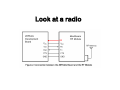
Look at a radio
int
That Radio ...
To read the data from the radio, we
could write a program that loops and
examines the CTS and Rx line looking for
data.
Thats POLLING
What if we want the radio to signal the
CPU when data is ready for it?
Thats an INTERRUPT
Interrupts
A signal (hardware or software) that
interrupts the normal flow of execution
and forces a temporary branch to a
service routine (ISR)
Common in ALL microprocessors and
microcontrollers
Interrupts
When an interrupt is triggered, the
current program counter is pushed onto
the stack, the working register set is
pushed and the interrupt service routine
is called. This is called Saving Context.
Microprocessor usually have different
return (RET) instructions for interrupt
service routines and for normal CALL
functions.
Hardware
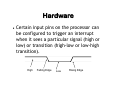
Certain input pins on the processor can
be configured to trigger an interrupt
when it sees a particular signal (high or
low) or transition (high-low or low-high
transition).
High
Falling Edge
Low
Rising Edge
Software
Interrupts can be triggered by software.
8086 INT instruction
Z16 TRAP instruction
Interrupts
Some microprocessors have 1 or 2 pins
for interrupts. Multiple external sources
have to share this and use some
mechanism to identify the source.
Microcontrollers typically have many pins
that can trigger an interrupt.
Interrupts
Interrupt – An asynchronous electrical
signal that indicates a specific reason to
interrupt the processor.
Interrupt vector – An address (a pointer)
that is the beginning of a block of code
that is executed when an interrupt is
received.
Interrupt Table - A collection of interrupt
addresses (a jump table).
Interrupts
Interrupt Handler = Interrupt Service
Routine - A subroutine for handling a
specific interrupt event.
Interrupt Number – An offset in the
interrupt table for that particular
interrupt.
Interrupts
At the completion of the ISR, control is
returned to the point in the program we
were executing when the interrupt
occurred (IRET)
Interrupts can have a priority just in case
several happen at the exact same time.
The interrupt with the highest priority is
called first.
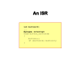
An ISR
int button=0;
...
#pragma interrupt
void button_isr(void)
{
button++;
if (button>4) button=1;
}
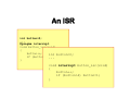
An ISR
int button=0;
...
#pragma interrupt
void button_isr(void)
{
button++;
int button=0;
if (button>4)...
button=1;
}
void interrupt button_isr(void)
{
button++;
if (button>4) button=1;
}
Common Interrupts
Timers
Data Received
Data Sent
WatchDog timer
Signal on pin
Change of signal on pin
Software Error
Enabling/Disabling
On most microcontrollers, once an
interrupt has been triggered, further
interrupts are disabled. When the ISR
returns control, interrupts are reenabled.
Software can enable and disable
interrupts at any time.
Why would you want to
disable interrupts?
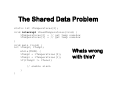
The Shared Data Problem
static int iTemperatures[2];
void interrupt vReadTemperatures(void) {
iTemperatures[0] = // get temp somehow
iTemperatures[1] = // get temp somehow
}
void main (void) {
int iTemp0, iTemp1;
while(TRUE) {
iTemp0 = iTemperatures[0];
iTemp1 = iTemperatures[1];
if(iTemp0 != iTemo1)
Whats wrong
with this?
// enable alarm
}
}
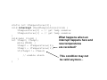
static int iTemperatures[2];
void interrupt vReadTemperatures(void) {
iTemperatures[0] = // get temp somehow
iTemperatures[1] = // get temp somehow
}
What happens when an
void main (void) {
interrupt happens here and
int iTemp0, iTemp1;
while(TRUE) {
new temperatures
iTemp0 = iTemperatures[0];
are recorded?
iTemp1 = iTemperatures[1];
if(iTemp0 != iTemo1)
// enable alarm
}
}
This condition may not
be valid anymore...
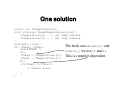
One solution
static int iTemperatures[2];
void interrupt vReadTemperatures(void) {
iTemperatures[0] = // get temp somehow
iTemperatures[1] = // get temp somehow
}
void main (void) {
The book uses disable() and
int iTemp0, iTemp1;
while(TRUE) {
enable(), we use DI and EI
DI;
iTemp0 = iTemperatures[0]; This is compiler dependent.
iTemp1 = iTemperatures[1];
EI;
if(iTemp0 != iTemo1)
// enable alarm
}
}
While processing an interrupt,
further interrupts are disabled.
Why might you want to
re-enable them (while an
ISR is still executing)?
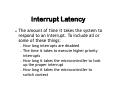
Interrupt Latency
The amount of time it takes the system to
respond to an interrupt. To include all or
some of these things:
How long interrupts are disabled
The time it takes to execute higher priority
interrupts
How long it takes the microcontroller to look
up the proper interrupt
How long it takes the microcontroller to
switch context
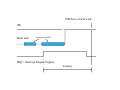
ISR does critical work
ISR
Main task
Interrupts disabled
IRQ = Interrupt Request Signal
Latency
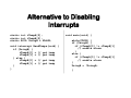
Alternative to Disabling
Interrupts
static int iTempA[2];
static int iTempB[2];
static BOOL UsingB = FALSE;
void interrupt ReadTemps(void) {
if (UsingB) {
iTempA[0] = // get temp
iTempA[1] = // get temp
} else {
iTempB[0] = // get temp
iTempB[1] = // get temp
}
}
void main(void) {
while(TRUE) {
if (UsingB) {
if (iTempB[0] != iTempB[1]
// enable alarm
}
else {
if (iTempA[0] != iTempA[1]
// enable alarm
}
UsingB = !UsingB;
}
ISR
Main task
Interrupts disabled
Missed/Avoided interrupts
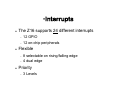
•Interrupts
The Z16 supports 24 different interrupts
12 GPIO
12 on-chip peripherals
Flexible
8 selectable on rising/falling edge
4 dual edge
Priority
3 Levels
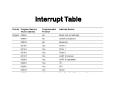
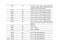
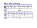
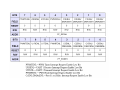
Interrupt Table
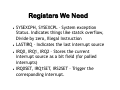
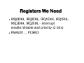
Registers We Need
SYSEXCPH, SYSEXCPL – System exception
Status. Indicates things like statck overflow,
Divide by zero, Illegal Instruction
LASTIRQ – Indicates the last interrupt source
IRQ0, IRQ1, IRQ2 – Stores the current
interrupt source as a bit field (for polled
interrupts)
IRQ0SET, IRQ1SET, IRS2SET – Trigger the
corresponding interrupt.
Registers We Need
IRQ0ENH, IRQ0ENL, IRQ1ENH, IRQ1ENL,
IRQ2ENH, IRQ2ENL – Interrupt
enable/disable and priority (2 bits)
PAIMUX1, , PCIMUX
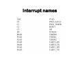
Interrupt names
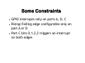
Some Constraints
GPIO interrupts only on ports A, D, C
Rising/Falling edge configurable only on
port A or D
Port C bits 0,1,2,3 triggers an interrupt
on both edges
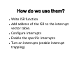
How do we use them?
Write ISR function
Add address of the ISR to the interrupt
vector table.
Configure interrupts
Enable the specific interrupts
Turn on interrupts (enable interrupt
trapping)
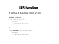
ISR function
A normal C function. More or less
#pragma interrupt
void isr_button(void) {
button++;
if (button>4) button=1;
}
or
void interrupt isr_button(void) {
button++;
if (button>4) button=1;
}
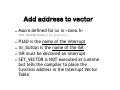
Add address to vector
Macro defined for us in <zneo.h>
SET_VECTOR(P3AD,isr_button);
P3AD is the name of the interrupt
isr_button is the name of the ISR
ISR must be declared an interrupt
SET_VECTOR is NOT executed at runtime
but tells the compiler to place the
function address in the Interrupt Vector
Table
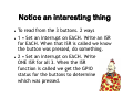
Notice an interesting thing
To read from the 3 buttons. 2 ways
1 = Set an interrupt on EACH. Write an ISR
for EACH. When that ISR is called we know
the button was pressed, do something.
2 = Set an interrupt on EACH. Write
ONE ISR for all 3. When the ISR
function is called we get the GPIO
status for the buttons to determine
which was pressed.
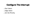
Configure The Interrupt
Port Select
Edge select
Set the Priority
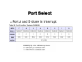
Port Select
Port A and D share in interrupt
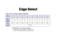
Edge Select
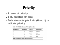
Priority
3 Levels of priority
3 IRQ registers (24 bits)
Each interrupts gets 2 bits (H and L) to
indicate priority.
Priority
Interrupt priority controls what
happens when two or more interrupt
signals are received at the same time.
Not what happens while one interrupt
is being handled and another interrupt
event occurs.
What happens while one
interrupt is being handled and
another interrupt event
occurs?
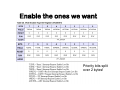
Enable the ones we want
Priority bits split
over 2 bytes!
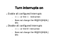
Turn interrupts on
Enable all configured Interrupts
EI() or the EI instruction
Does not change the IRQ{012}EN{HL}
bits
Disable all configured Interrupts
DI() or the DI instruction
Does not change the IRQ{012}EN{HL}
bits
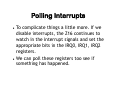
Polling Interrupts
To complicate things a little more. If we
disable interrupts, the Z16 continues to
watch in the interrupt signals and set the
appropriate bits in the IRQ0, IRQ1, IRQ2
registers.
We can poll these registers too see if
something has happened.
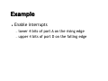
Example
Enable interrupts
lower 4 bits of port A on the rising edge
upper 4 bits of port D on the falling edge
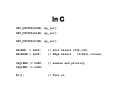
In C
SET_VECTOR(P0AD, my_isr);
SET_VECTOR(P1AD, my_isr);
...
SET_VECTOR(P7AD, my_isr);
PAIMUX = 0xF0;
PAIEDGE = 0x0F;
// Port Select (0=A,1=D)
// Edge Select
(0=fall,1=rise)
IRQ1ENH |= 0xFF;
IRQ1ENL |= 0x00;
// enable and priority
EI();
// Turn on
Interrupt Recipe
Interrupts
1. Determine which interrupts you need to watch
2. Write the necessary ISRs
3. Configure port A or D bits (PAIMUX)
4. Configure edges for port A/D (PAIEDGE)
5. Enable and set priority of each interrupt (IRQxENH
and IRQxENL}
6. Assign the ISR to the interrupt vector
(SET_VECTOR)
7. Enable interrupts (EI)
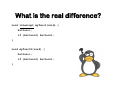
What is the real difference?
void interrupt myfunc1(void) {
button++;
if (button>4) button=1;
}
void myfunct2(void) {
button++;
if (button>4) button=1;
}
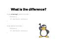
What is the difference?
void interrupt myfunc1(void) {
button++;
if (button>4) button=1;
}
void myfunct2(void) {
button++;
if (button>4) button=1;
}
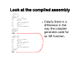
Look at the compiled assembly
_myfunc1:
LINK #0
PUSHMLO
#1
INC
_button:RAM
LD
R0,#4
CP
_button:RAM,R0
JP
LE,_3_L_6
LD
R0,#1
LD
_button:RAM,R0
_3_L_6:
POPMLO#1
UNLINK
IRET
_myfunct2:
LINK #0
INC
_button:RAM
LD
R0,#4
CP
_button:RAM,R0
JP
LE,_4_L_9
LD
R0,#1
LD
_button:RAM,R0
_4_L_9:
UNLINK
RET
Clearly there is a
difference in the
way the compiler
generates code for
an ISR function.
Software Generated
We can't simply call an ISR function like
we would a normal function.
To cause an interrupt from software,
write a “1” to the bit position of the
corresponding interrupt in IRQ0SET,
IRQ1SET or IRQ2SET.
The Z16 interrupt controller treats these
writes the same as a hardware generated
interrupt.
Using interrupts ...
• ... On the LAB board, to read a button
Not all buttons can trigger an interrupt.
Why Not?
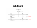
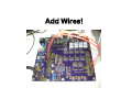
Lab Board
How can we “fix” that?
So that all 3 buttons can cause an
interrupt?
Add Wires!
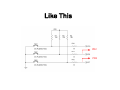
How does that work?
Like This
PD2
PD3
What get executed?
• SET_VECTOR(P0AD, my_isr);
Example
InterruptCounter
Update the 8 bit latch counter example to
count button presses using interrupts
Can we change the interrupt
vector table at runtime?
Can we change which ISR is
called by an interrupt at
runtime?
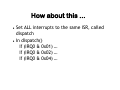
How about this ...
Set ALL interrupts to the same ISR, called
dispatch
In dispatch()
if (IRQ0 & 0x01) …
if (IRQ0 & 0x02) …
if (IRQ0 & 0x04) …
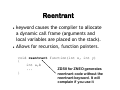
Reentrant
keyword causes the compiler to allocate
a dynamic call frame (arguments and
local variables are placed on the stack).
Allows for recursion, function pointers.
void reentrant function(int x, int y)
{
int a,b
...
ZDSII for ZNEO generates
}
reentrant code without the
reentrant keyword. It will
complain if you use it
Reentrant
Functions that require dynamic frames
include:
Any recursive function, including indirect
recursion.
Any function called through a pointer.
Any function that might be called by an
interrupt handler, unless it takes no
parameters and has no local non-static data.
Volatile
The volatile keyword indicates that the
storage is likely to change at anytime and
be changed by something the compiler
isn't aware of (like an interrupt service
routine, or IO on a SFR).
How can a variable change
value and compiler not be
aware of that?
The compiler know about
assignments ...
button = 33;
Why we need volatile
Memory-mapped peripheral registers
Global variables modified by an interrupt
service routine
Global variables within a multi-threaded
application
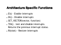
Architecture Specific Functions
EI() - Enable interrupts
DI() - Disable interrupts
SET_VECTOR(vector, function)
TDI() – test and disable interrupts.
Returns the previous interrupt status.
RI(stat) - Restore interrupts
What all do you need to do, if
you need to process interrupts
WHILE you are already
processing an interrup?
You Will Use
Interrupts for
Almost Everything!