1
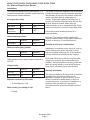
Installation and
User's Manual for
Modular Flaked & Nugget Ice Machines
Models F0522, F0822, F1222, F1522,
N0422, N0622, N0922 and N1322
Air Cooled, Water Cooled and Remote Air Cooled
N0422, F0522, N0622, F0822, N0922, F1222, N1322, F1522
Air, Water or Remote User Manual
Introduction
This ice machine is the result of years of
experience with flaked and nugget ice machines.
The latest in electronics has been coupled with the
time tested Scotsman flaked ice system to provide
reliable ice making and the features needed by
customers. The features include easily accessible
air filters, simple conductivity water level sensing,
evaporator clearing at shut down, photo-eye
sensing bin control and the ability to add options.
Table of Contents
Installation: . . . . . . . . . . . . . . . . . . . . . . . . . . . . . . . . . . . . . . . . . . . Page 2
Location:
. . . . . . . . . . . . . . . . . . . . . . . . . . . . . . . . . . . . . . . . . . . . Page 3
N0422, F0522, N0622, F0822, N0822 Cabinet Layout . . . . . . . . . . . . . . . . . . . . . Page 4
N0922, F1222, N1322, F1522 Cabinet Layout . . . . . . . . . . . . . . . . . . . . . . . . . Page 5
Unpacking & Install Prep . . . . . . . . . . . . . . . . . . . . . . . . . . . . . . . . . . . . Page 6
Water - Air or Water Cooled
. . . . . . . . . . . . . . . . . . . . . . . . . . . . . . . . . . Page 7
Electrical - All Models . . . . . . . . . . . . . . . . . . . . . . . . . . . . . . . . . . . . . . Page 8
Refrigeration - Remote Condenser Models . . . . . . . . . . . . . . . . . . . . . . . . . . . Page 9
Remote Condenser Location - Limits . . . . . . . . . . . . . . . . . . . . . . . . . . . . . . Page 10
For The Installer: Remote Condenser
. . . . . . . . . . . . . . . . . . . . . . . . . . . . . Page 11
Precharged Line Routing - Remote Only . . . . . . . . . . . . . . . . . . . . . . . . . . . . Page 12
Coupling Instructions - Remote Only . . . . . . . . . . . . . . . . . . . . . . . . . . . . . . Page 13
Water - Remote Models . . . . . . . . . . . . . . . . . . . . . . . . . . . . . . . . . . . . . Page 14
Final Check List . . . . . . . . . . . . . . . . . . . . . . . . . . . . . . . . . . . . . . . . . Page 15
Initial Start Up and Maintenance . . . . . . . . . . . . . . . . . . . . . . . . . . . . . . . . Page 16
Maintenance: Scale Removal and Sanitation . . . . . . . . . . . . . . . . . . . . . . . . . . Page 17
Maintenance: Check Top Bearing
. . . . . . . . . . . . . . . . . . . . . . . . . . . . . . . Page 18
Bearing Service . . . . . . . . . . . . . . . . . . . . . . . . . . . . . . . . . . . . . . . . . Page 19
Maintenance: Sensors
. . . . . . . . . . . . . . . . . . . . . . . . . . . . . . . . . . . . . Page 20
Options . . . . . . . . . . . . . . . . . . . . . . . . . . . . . . . . . . . . . . . . . . . . . Page 21
What to do before calling for service . . . . . . . . . . . . . . . . . . . . . . . . . . . . . . Page 22
This user and installation manual is organized in
three main sections: installation, operation, and
maintenance.
July 2009
Page 1
N0422, F0522, N0622, F0822, N0922, F1222, N1322, F1522
Air, Water or Remote User Manual
Installation:
This machine is designed to be used indoors, in a
The quality of the water supplied to the ice machine
controlled environment. Operation outside the limits will have an impact on the time between cleanings
listed here will void the warranty.
and ultimately on the life of the product. Water can
contain impurities either in suspension or in
solution. Suspended solids can be filtered out. In
Air temperature limits
solution or dissolved solids cannot be filtered, they
must be diluted or treated. Water filters are
Minimum
Maximum
recommended to remove suspended solids. Some
Ice maker
50oF.
100oF.
filters have treatment in them for suspended solids.
Remote
-20oF.
120oF.
Check with a water treatment service for a
condenser
recommendation.
Water temperature limits
Minimum
All models
o
40 F.
Maximum
RO water. This machine can be supplied with
Reverse Osmosis water, but the water conductivity
must be no less than 10 microSiemens/cm.
100oF.
Potential for Airborne Contamination
Water pressure limits (potable)
All models
Minimum
Maximum
20 psi
80 psi
Water pressure limit to water cooled condenser is
150 PSI
Voltage limits
Minimum
Maximum
115 volt
104
126
208-230 60 Hz
198
253
Minimum conductivity (RO water)
• 10 microSiemens / CM
Water Quality (ice making circuit)
Installing an ice machine near a source of yeast or
similar material can result in the need for more
frequent sanitation cleanings due to the tendency
of these materials to contaminate the machine.
Most water filters remove chlorine from the water
supply to the machine which contributes to this
situation. Testing has shown that using a filter that
does not remove chlorine, such as the Scotsman
Aqua Patrol, will greatly improve this situation.
Warranty Information
The warranty statement for this product is provided
separately from this manual. Refer to it for
applicable coverage. In general warranty covers
defects in material or workmanship. It does not
cover maintenance, corrections to installations, or
situations when the machine is operated in
circumstances that exceed the limitations printed
above.
• Potable
November 2009
Page 2
N0422, F0522, N0622, F0822, N0922, F1222, N1322, F1522
Air, Water or Remote User Manual
Location:
While the machine will operate satisfactorily within
the listed air and water temperature limits, it will
produce more ice when those temperatures are
nearer the lower limits. Avoid locations that are hot,
dusty, greasy or confined. Air cooled models need
plenty of room air to breathe. Air cooled models
must have at least six inches of space at the back
for air discharge; however, more space will allow
better performance.
Airflow
Air flows into the front of the cabinet and out the
back. The air filters are on the outside of the front
panel and are easily removed for cleaning.
Bin compatibility
All models have the same footprint: 22 inches wide
by 24 inches deep. Confirm available space when
replacing a prior model.
Bin & adapter list:
•
•
•
•
•
•
B222S or B322S – no adapter needed
B330P or B530P or B530S – Use KBT27
B842S – KBT39
B948S – KBT38 for single unit
B948S – KBT38-2X for two units side by side
BH1100, BH1300 and BH1600 upright bins
include filler panels to accommodate a 22
inch wide ice machine. No adapter is
needed.
BH900: Use baffle kit KBBF1 for these models.
Dispenser compatibility
Only nugget ice models may be used with ice
dispensers. Flaked ice is not dispensable.
• ID150 – use KBT42 and KDIL-PN-150,
includes KVS, KNUGDIV and R629088514
• ID200 – use KBT43 and KNUGDIV and KVS
• ID250 – use KBT43 and KNUGDIV and KVS
Airflow
See sales literature for other brand model ice and
beverage dispenser applications.
Options
Side air flow kits KPFSA223 or KPFSA227 are
available for air cooled models. A filter kit for the
remote condenser is KERCF
Ice is made until it fills the bin enough to block an
infrared light beam inside the base of the machine.
A field installed kit is available to adjust the
maintained ice level lower. The kit number is KVS.
The standard controller has excellent diagnostic
capabilities and communicates to the user through
the AutoAlert light panel, seen through the front
panel. Field installed kits are available that can log
data and provide additional information when the
front panel is removed. The kit numbers are KSBU
and KSB-NU. See page 21.
Other Bins & Applications:
Note the drop zone and ultrasonic sensor locations
in the illustrations on the next pages.
Scotsman ice systems are designed and
manufactured with the highest regard for safety
and performance. Scotsman assumes no liability of
responsibility of any kind for products
manufactured by Scotsman that have been altered
in any way, including the use of any part and/or
other components not specifically approved by
Scotsman.
Scotsman reserves the right to make design
changes and/or improvements at any time.
Specifications and design are subject to change
without notice.
July 2009
Page 3
N0422, F0522, N0622, F0822, N0922, F1222, N1322, F1522
Air, Water or Remote User Manual
N0422, F0522, N0622, F0822 Cabinet Layout
55.9
22.00
58.1
22.89
REF.
31.8
12.50
ULTRA SONIC
BIN LEVEL
SENSOR
OPTIONAL
[58.5]
23.00
61
24.00
REF.
PLAN VIEW
41.9
16.50
7.4
2.92
ICE DROP
OPENING
7.1
2.81
FRONT VIEW
10.9
4.30
REMOTE COND.
LIQUID LINE
3/8" MALE CPLG.
.88 DIA.
ELECTRICAL
CONNECTION
3/8" FPT
CONDENSER
WATER
INLET
3/8" FLARE
MACHINE
WATER
INLET
37
14.55
55.9
22.00
16.5
6.48
Note: Bin Top Cut-outs for
drop zone should include
ultrasonic sensor location
39.1
15.40
31.4
12.35
44.6
17.55
3/4" FPT
DRAIN
48
18.88
37.1
14.60
31.5
12.40
6.8
2.68
1/2" FPT
CONDENSER
DRAIN
49
19.31
4
1.59
3/4" FPT
DRAIN
REMOTE COOLED
BACK VIEW
5.5
2.17
WATER COOLED
BACK VIEW
5.5
2.17
REMOTE COND.
DISCHARGE LINE
1/2" MALE CPLG.
.88 DIA.
ELECTRICAL
CONNECTION
8.5
3.33
6.7
2.63
4
1.59
LOUVER AND
REMOVABLE FILTER
A/C UNITS ONLY
18.8
7.40
27.8
10.94
.88 DIA.
ELECTRICAL
ACCESS
3/8" FLARE
MACHINE
WATER
INLET
37.2
14.65
31.5
12.40
6.8
2.68
61
24.00
AIR COOLED
BACK VIEW
3/4" FPT
DRAIN
[2.4]
.92
LEFT SIDE VIEW
4
1.59
[ cm }
5.5
2.17
In
December 2009
Page 4
N0422, F0522, N0622, F0822, N0922, F1222, N1322, F1522
Air, Water or Remote User Manual
N0922, F1222, N1322, F1522 Cabinet Layout
55.9
22.00
58.1
22.89
REF.
31.8
12.50
ULTRA SONIC
BIN LEVEL
SENSOR
OPTIONAL
[68.6]
27.00
61
24.00
REF.
LOUVER AND
REMOVABLE FILTER
A/C UNITS ONLY
PLAN VIEW
41.9
16.50
7.4
2.92
ICE DROP
OPENING
7.1
2.81
55.9
22.00
16.5
6.48
Note: Bin Top Cut-outs for
drop zone should include
ultrasonic sensor location
FRONT VIEW
10.9
4.30
.88 DIA.
ELECTRICAL
ACCESS
.88 DIA.
ELECTRICAL
ACCESS
3/8" FLARE
MACHINE
WATER
INLET
39.2
15.44
34
13.39
REMOTE COND.
DISCHARGE LINE
1/2" CPLG
3/8" FLARE
MACHINE
WATER
INLET
3/8" FPT
CONDENSER
WATER INLET
47.2
18.59
REMOTE COND.
LIQUID LINE
3/8" CPLG
55.5
21.84
47.2
18.59
34
13.39
8.6
3.37
6.8
2.67
45.8
18.05
3/4" FPT
DRAIN
4
1.59
50.3
19.80
1/2" FPT
CONDENSER
DRAIN
6.8
2.67
5.5
2.17
WATER COOLED
BACK VIEW
5.5
2.17
3/4" FPT
DRAIN
4
1.59
REMOTE COOLED
BACK VIEW
18.8
7.39
27.8
10.93
.88 DIA.
ELECTRICAL
ACCESS
3/8" FLARE
MACHINE
WATER
INLET
47.3
18.64
34
13.39
6.8
2.67
3/4" FPT
DRAIN
4
1.59
61
24.00
AIR COOLED
BACK VIEW
LEFT SIDE VIEW
2.3
.92
[ cm }
In
December 2009
Page 5
N0422, F0522, N0622, F0822, N0922, F1222, N1322, F1522
Air, Water or Remote User Manual
Unpacking & Install Prep
Remove the carton from the skid. Check for hidden Panel Removal
freight damage, notify the carrier immediately if any
is found. Retain the carton for the carrier’s
inspection.
The machine is not bolted to the skid. If strapped
remove the strap.
Place on Bin or Dispenser
If reusing an existing bin, be sure that the bin is in
good shape and that the gasket tape on the top is
not torn up. Water leaks, not covered by warranty,
could result from a poor sealing surface. If
installing a remote or a remote low side, a new bin
is recommended due to the high cost to the user of
replacing an old bin when a remote system is on
top.
Install the correct adapter, following the directions
supplied with that adapter.
1. Locate and loosen the two screws at the front
edge of the top panel.
Hoist the machine onto the adapter.
2. Pull the front panel out at the top until it clears
the top panel.
Note: The machine is heavy! Use of a mechanical
lift is recommended.
Position the machine on the bin or adapter. Secure
with straps from the hardware bag packed with the
machine, or those supplied with the adapter.
Remove any plastic covering the stainless steel
panels.
3. Lift the front panel up and off the machine.
4. Remove two screws at the front of the top panel.
Lift up the front of the top panel, push the top panel
back an inch, then lift to remove.
5. Locate and loosen the screw holding each side
panel to the base. Left side panel also has a screw
holding it to the control box.
Note: The standard machine set up includes visible 6. Pull the side panel forward to release it from the
on and off switches. Those can be covered up by
back panel.
changing the bezel in the front panel’s trim strip.
Button Switch Bezel
Remove any packaging, such as tape or foam
To change bezels: Remove the front panel and
blocks, that may be near the gear reducer or ice
push snaps of standard bezel in and pull the bezel
chute.
out of the front panel trim strip.
Level the bin and ice machine front to back and left
Obtain other bezel. Push into the trim strip from the
to right by using the bin leg levelers.
front until it snaps into place. Return the front panel
to its original position and secure it to the cabinet
February 2012
Page 6
N0422, F0522, N0622, F0822, N0922, F1222, N1322, F1522
Air, Water or Remote User Manual
Water - Air or Water Cooled
The water supply for ice making must be cold,
potable water. There is a single 3 8” male flare
potable water connection on the back panel. Water
cooled models also have a 3 8” FPT inlet connection
for the water cooled condenser. Chilled water can
also be used for this connection.
Water Inlet
Backflow
The design of the float valve and reservoir
prevents potable water backflow by means of a
1" air gap between the reservoir's maximum water
level and the float valve water inlet orifice.
Drain Vent
Condensate
Drain
Drain
There is one ¾” FPT condensate drain fitting at the
back of the cabinet. Water cooled models also
have a ½” FPT discharge drain connection on the
back panel.
Building Drain
Attach Tubing
Connect the potable water supply to the potable
water fitting, 3 8” OD copper tubing or the equivalent
is recommended.
Air Cooled or Remote Plumbing
Water filtration is recommended. If there is an
existing filter, change the cartridge.
Connect the water cooled water supply to the
condenser inlet.
Condenser
Water Inlet
Note: Do NOT filter water to the water cooled
condenser circuit.
Drains - use rigid tubing: Connect the drain tube to
the condensate drain fitting. Vent the drain.
Connect the water cooled condenser drain tube
to the condenser outlet. Do not vent this drain.
Potable
Water
Inlet
Drain Vent
Condensate
Drain
Do not Tee ice machine drains into the drain tube
from the ice storage bin or dispenser. Back ups
could contaminate and / or melt the ice in the bin or
dispenser. Be sure to vent the bin drain.
Condenser
Drain
Follow all local and national codes for tubing, traps
and air gaps.
Water Cooled Plumbing
July 2009
Page 7
N0422, F0522, N0622, F0822, N0922, F1222, N1322, F1522
Air, Water or Remote User Manual
Electrical - All Models
Connect electrical power to wires inside the
The machine does not include a power cord, one
must be field supplied or the machine hard wired to junction box in the back of the cabinet. Use a strain
relief and connect a ground wire to the ground
the electrical power supply.
screw.
The junction box for the power cord is on the back
Remote models power the condenser fan motor
panel. See the next page.
from marked leads in the junction box.
Refer to the dataplate on the machine for minimum
circuit ampacity and determine the proper wire size Do not use an extension cord. Follow all local and
for the application. The dataplate (on the back of
national codes.
the cabinet) also includes the maximum fuse size.
Model
Dimensions
w" x d" x h"
Voltage
Volts/Hz/Phase
Condenser
Type
N0422A-1
22 x 24 x 23
115/60/1
N0422W-1
same
F0522A-1
same
F0522W-1
Min Circ
Ampacity
Max Fuse Size or HACR
Type Circuit Breaker
Air
15.2
20
111/60/1
Water
14.4
20
115/60/1
Air
15.2
20
same
115/60/1
Water
14.4
20
N0622A-1
same
115/60/1
Air
18.3
25
N0622W-1
same
115/60/1
Water
16.7
25
N0622R-1
same
115/60/1
Remote
19.4
25
N0622A-32
same
208-230/60/1
Air
9.8
15
N0622W-32
same
208-230/60/1
Water
8.9
15
F0822A-1
same
115/60/1
Air
18.3
25
F0822W-1
same
115/60/1
Water
16.7
25
F0822R-1
same
115/60/1
Remote
19.4
25
F0822A-32
same
208-230/60/1
Air
9.8
15
F0822W-32
same
208-230/60/1
Water
8.9
15
N0922A-32
22 x 24 x 27
208-230/60/1
Air
12.5
15
N0922W-32
same
208-230/60/1
Water
11.3
15
N0922R-32
same
208-230/60/1
Remote
12.3
15
N0922A-3
same
208-230/60/3
Air
13.0
15
N0922R-3
same
208-230/60/3
Remote
12.8
15
F1222A-32
same
208-230/60/1
Air
12.5
15
F1222W-32
same
208-230/60/1
Water
11.3
15
F1222R-32
same
208-230/60/1
Remote
12.3
15
F1222A-3
same
208-230/60/3
Air
13.0
15
F1222W-3
same
208-230/60/3
Water
11.8
15
F1222R-3
same
208-230/60/3
Remote
12.8
15
N1322A-32
same
208-230/60/1
Air
19.1
30
N1322W-32
same
208-230/60/1
Water
17.9
30
N1322R-32
same
208-230/60/1
Remote
18.9
30
F1522A-32
same
208-230/60/1
Air
19.1
30
F1522W-32
same
208-230/60/1
Water
17.9
30
November 2009
Page 8
N0422, F0522, N0622, F0822, N0922, F1222, N1322, F1522
Air, Water or Remote User Manual
Refrigeration - Remote Condenser Models
Remote condenser models have additional
installation needs.
Ground Wire
Connection
The correct remote condenser fan and coil must be
connected to the ice making head. Liquid and
discharge tubing connections are on the back of
the ice machine cabinet. Pre-charged tubing kits
are available in several lengths to accommodate
most installations. Order the one that just exceeds
the length needed for the installation.
Junction
Box
Cover
Black
Install
Strain
Relief
White
Ground
Power
Supply
Wires
The kit numbers are:
•
•
•
•
RTE10
RTE25
RTE40
RTE75
There are limits as to how far away from the ice
machine and where the remote condenser can be
located. See page 10 for those limits.
The correct condenser must be used.
Reference: Electrical Detail, air or water cooled.
To Remote
Condenser
Fan Motor
Blue
Install
Strain
Relief
Ground Wire
Connection
Install
Strain
Relief
Junction
Box
Cover
Black
White
Ground
Power
Supply
Wires
Ice Machine
Model
Voltage
Condenser
Model
F0822R,
N0622R
115
ERC111-1
F1222R,
N0922R
208-230
ERC311-32
N1322R
208-230
ERC311-32
Do not reuse condenser coils contaminated with
mineral oil (used with R-502 for example). They will
cause compressor failure and will void the
warranty.
A headmaster is required for all remote condenser
systems. Prior condensers did not have a
headmaster. New head / prior condenser retrofits
can use headmaster kit KPFHM.
Use of non-Scotsman condensers requires
pre-approval from Scotsman Engineering.
Reference: Electrical Detail - Remote
July 2009
Page 9
N0422, F0522, N0622, F0822, N0922, F1222, N1322, F1522
Air, Water or Remote User Manual
Remote Condenser Location - Limits
Use the following for planning the placement of the
condenser relative to the ice machine
Do NOT:
• Route a line set that rises, then falls, then
Location Limits - condenser location must not
exceed ANY of the following limits:
• Maximum rise from the ice machine to the
rises.
• Route a line set that falls, then rises, then
falls.
condenser is 35 physical feet
Calculation Example 1:
• Maximum drop from the ice machine to the
condenser is 15 physical feet
The condenser is to be located 5 feet below the ice
• Physical line set maximum length is 100 feet. machine and then 20 feet away horizontally.
• Calculated line set length maximum is 150.
5 feet x 6.6 = 33. 33 + 20 = 53. This location would
be acceptable
Calculation Formula:
Calculation Example 2:
• Drop = dd x 6.6 (dd = distance in feet)
• Rise = rd x 1.7 (rd = distance in feet)
• Horizontal Run = hd x 1 (hd = distance in
feet)
• Calculation: Drop(s) + Rise(s) + Horizontal
• Run = dd+rd+hd = Calculated Line Length
Configurations that do NOT meet these
requirements must receive prior written
authorization from Scotsman to maintain warranty.
The condenser is to be located 35 feet above and
then 100 feet away horizontally. 35 x 1.7 = 59.5.
59.5 +100 = 159.5. 159.5 is greater than the 150
maximum and is NOT acceptable.
Operating a machine with an unacceptable
configuration is misuse and will void the warranty.
hd
40.35"
22.87"
Remote Condenser
located above ice
machine.
rd
Max 35'
17.15"
Max 15'
dd
Remote condenser
located below ice
machine.
July 2009
Page 10
Condenser Distance &
Location Schematic
N0422, F0522, N0622, F0822, N0922, F1222, N1322, F1522
Air, Water or Remote User Manual
For The Installer: Remote Condenser
Locate the condenser as near as possible to the
interior location of the ice machine. Allow it plenty
of space for air and cleaning: keep it a minimum of
two feet away from a wall or other rooftop unit.
Note: The location of the condenser relative to the
ice machine is LIMITED by the specification on the
prior page.
Power Supply
from Ice Machine
Roof penetration. In many cases a roofing
contractor will need to make and seal the hole in
the roof for the line sets. The suggested hole
diameter is 2 inches.
Meet all applicable building codes.
Roof Attachment
Install and attach the remote condenser to the roof
of the building, using the methods and practices of
construction that conform to the local building
codes, including having a
roofing contractor secure
To
the condenser to the roof.
Pre-Charged
Refrigeration
Tubing
Remote Condenser
Remote Condenser
July 2009
Page 11
Liquid and
Discharge
Quick-Connects
N0422, F0522, N0622, F0822, N0922, F1222, N1322, F1522
Air, Water or Remote User Manual
Precharged Line Routing - Remote Only
Do not connect the precharged tubing until all
routing and forming of the tubing is complete. See
the Coupling Instructions for final connections.
Caution: Do NOT kink the refrigerant tubing while
routing it.
1. Each set of pre-charged tubing lines contains a
3/8” diameter liquid line, and a 1/2” diameter
discharge line. Both ends of each line have quick
connect couplings.
3. Route the refrigerant tubes thru the roof opening.
Follow straight line routing whenever possible.
Excess tubing may EITHER be coiled up INSIDE
the building OR cut out prior to connection to the
ice maker and condenser.
Note: The openings in the building ceiling or wall,
listed in the next step, are the minimum sizes
recommended for passing the refrigerant lines
through.
If the excess tubing is cut out, after re-brazing the
tubing must be evacuated prior to connection to the
ice maker or condenser.
2. Have the roofing contractor cut a minimum hole
for the refrigerant lines of 2”. Check local codes, a
separate hole may be required for the electrical
power supply to the condenser.
If the excess tubing is to be coiled, spiral it
horizontally to avoid excess trapping in the lines.
5. Have the roofing contractor seal the holes in the
roof per local codes
Power Supply
to Condenser
Pre-Charged
Tubing Line
Set
To Remote
Fan Motor
Condenser
Potable Water
Supply
Condensate
Drain
July 2009
Page 12
N0422, F0522, N0622, F0822, N0922, F1222, N1322, F1522
Air, Water or Remote User Manual
Coupling Instructions - Remote Only
The couplings on the ends of the pre-charged line
sets are self-sealing when installed properly.
Follow these instructions carefully.
loose in the refrigeration system. Note: As the
couplings are tightened, the diaphragms in the
quick connect couplings will begin to be pierced. As
that happens, there will be some resistance to
tightening the swivel nut.
These steps must be performed by an EPA
Certified Type II or higher technician.
Initial Connections
1. Remove the protector caps and plugs. Wipe the
seats and threaded surfaces with a clean cloth to
remove any possible foreign matter.
2. Lubricate the inside of the couplings, especially
the O-rings, with refrigerant oil. Oil packets are
supplied with Scotsman line sets.
3. Position the fittings on the correct connections
on the condenser and ice machine.
• Liquid
• Discharge
4c. Continue tightening the swivel nut until it
bottoms out or a very definite increase in
resistance is felt (no threads should be showing).
Final Connections:
4a. Begin by tightening the couplings together by
hand until it is certain that the threads are properly
engaged.
Critical Step!!!!!
5. Use a marker or pen to mark a line on the
coupling nut and unit panel. Then tighten the
coupling nut an additional one-quarter turn. The
line will show the amount that the nut turns. Do
NOT over tighten.
4b. Then using two wrenches tighten the coupling
until it bottoms out or a definite increase in
resistance is felt.
It is important that ONLY the nut on the
pre-charged tube be turned, or the diaphragms will
be torn out by the piercing knives and they will be
6. After all connections have been made, and after
the receiver outlet valve has been opened (do not
open yet), check the couplings for leaks.
July 2009
Page 13
N0422, F0522, N0622, F0822, N0922, F1222, N1322, F1522
Air, Water or Remote User Manual
Water - Remote Models
Drains - use rigid tubing: Connect the drain tube to
the condensate drain fitting. Vent the drain.
The water supply for ice making must be cold,
potable water. There is a single 3 8” male flare
potable water connection on the back panel.
Do not Tee ice machine drains into the drain tube
from the ice storage bin or dispenser. Back ups
could contaminate and / or melt the ice in the bin or
The design of the float valve and reservoir prevents dispenser. Be sure to vent the bin drain.
potable water backflow by means of a 1" air gap
Follow all local and national codes for tubing, traps
between the reservoir's maximum water level and
and air gaps.
the float valve water inlet orifice.
Backflow
Drain
There is one ¾” FPT condensate drain fitting at the
back of the cabinet.
To Remote Condenser
Attach Tubing
Connect the potable water supply to the potable
water fitting, 3 8” OD copper tubing or the
equivalent is
recommended.
Potable Water
Water filtration is
recommended. If
there is an
existing filter,
change the
cartridge.
Drain Vent
Condensate
Drain
July 2009
Page 14
N0422, F0522, N0622, F0822, N0922, F1222, N1322, F1522
Air, Water or Remote User Manual
Final Check List
After connections:
Control Operation
1. Wash out the bin. If desired, the interior of the
bin could be sanitized.
Use and Operation
2. Locate the ice scoop (if supplied) and have it
available for use when needed.
3. Remote only: Switch on the electrical power
to warm up the compressor. Do not start the
machine for 4 hours.
Final Check List:
1. Is the unit located indoors in a controlled
environment?
2. Is the unit located where it can receive adequate
cooling air?
Once started, the ice machine will automatically
make ice until the bin or dispenser is full of ice.
When ice level drops, the ice machine will resume
making ice.
Caution: Do not place anything on top of the ice
machine, including the ice scoop. Debris and
moisture from objects on top of the machine can
work their way into the cabinet and cause serious
damage. Damage caused by foreign material is not
covered by warranty.
Power
No
Water
On
3. Has the correct electrical power been supplied to
the machine?
Status
4. Have all the water supply connections been
made?
5. Have all the drain connections been made?
6. Has the unit been leveled?
7. Have all unpacking materials and tape been
removed?
8. Has the protective covering on the exterior
panels been removed?
9. Is the water pressure adequate?
10. Have the drain connections been checked for
leaks?
11. Has the bin interior been wiped clean or
sanitized?
Time to
Clean
Off
There are four indicator lights at the front of the
machine that provide information on the condition
of the machine.
Indicator Lights:
•
•
•
•
Power
Status
Water
De-scale & Sanitize
Note: If the De-Scale & Sanitize light is ON,
following the cleaning process will clear the light for
another cleaning time internal.
Two button switches are at the front – On and Off.
12. Have any water filter cartridges been replaced? To switch the machine OFF, push and release the
Off button. The machine will shut off at the end of
13. Have all required kits and adapters been
the next cycle.
properly installed?
To switch the machine ON, push and release the
On button. The machine will go through a start up
process and then resume ice making.
February 2012
Page 15
N0422, F0522, N0622, F0822, N0922, F1222, N1322, F1522
Air, Water or Remote User Manual
Initial Start Up and Maintenance
1. Turn the water supply on.
Sensor Cleaning: Every time the scale is removed.
2. Switch the electrical power on. Confirm voltage
is correct for the model.
Top bearing check: At least twice a year or every
time the scale is removed.
3. Push and release the On button. The machine
will start in about two minutes.
Maintenance: Air filters
1. Pull air filter(s) from panel.
4. Soon after starting, air cooled models will begin
to blow warm air out the back of the cabinet
2. Wash the dust and grease off the filter(s).
and water cooled models will drain warm water
from the condenser drain tube. Remote
3. Return it(them) to their original position(s).
models will be discharging warm air from the
remote condenser. After about 5 minutes, ice
Do not operate the machine without the filter in
will begin to drop into the bin or dispenser.
place except during cleaning.
5. Check the machine for unusual rattles. Tighten
any loose screws, be sure no wires are rubbing Maintenance: Air cooled condenser
moving parts. Check for tubes that rub.
If the machine has been operated without a filter
6. Fill out the warranty registration form and either the air cooled condenser fins will need to be
cleaned.
file it on line or mail it.
They are located under the fan blades. The
services of a refrigeration technician will be
required to clean the condenser.
7. Notify the user of the maintenance
requirements and whom to call for service.
Maintenance
Maintenance: Remote air cooled condenser
This ice machine needs five types of maintenance:
• Air cooled and remote models need their air
•
•
•
•
filters or condenser coils cleaned regularly.
All models need scale removed from the
water system.
All models require regular sanitization.
All models require sensor cleaning.
All models require a top bearing check.
Maintenance Frequency:
Air filters: At least twice a year, but in dusty or
greasy air, monthly.
The condenser fins will occasionally need to be
cleaned of leaves, grease or other dirt. Check the
coil every time the ice machine is cleaned.
Maintenance: Exterior Panels
The front and side panels are durable stainless
steel. Fingerprints, dust and grease will require
cleaning with a good quality stainless steel cleaner
Note: If using a sanitizer or a cleaner that contains
chlorine on the panels, after use be sure to wash
the panels with clean water to remove chlorine
residue.
Scale removal. At least twice a year, in some water
Maintenance: Water filters
conditions it might be every 3 months. The yellow
De-Scale & Sanitize light will switch on after a set
If the machine has been connected to water filters,
period of time as a reminder. The default time
check the cartridges for the date they were
period is 6 months of power up time.
replaced or for the pressure on the gauge. Change
cartridges if they’ve been installed more than 6
Sanitizing: Every time the scale is removed or as
months or if the pressure drops too much during
often as needed to maintain a sanitary unit.
ice making.
July 2009
Page 16
N0422, F0522, N0622, F0822, N0922, F1222, N1322, F1522
Air, Water or Remote User Manual
Maintenance: Scale Removal and Sanitation
Note: Following this procedure will reset the
de-scale and sanitize light.
1. Remove front panel.
2. Push and release the Off button.
Disconnect
Tubing
From Sensor
3. Remove ice from bin or dispenser.
4. Turn the water supply to the float valve OFF.
5. Drain the water and evaporator by
disconnecting the leg of the hose connected to
the water sensor and draining it into the bin.
Return the hose to its original position.
6. Remove the water reservoir cover.
7. Mix a solution of 8 ounces of Scotsman Clear
One Scale Remover and 3 quarts of 95-115
degree F. potable water.
Ice machine scale remover
contains acids. Acids can
cause burns.
If concentrated cleaner
comes in contact with skin,
flush with water. If swallowed,
do NOT induce vomiting.
Give large amounts of water
or milk. Call Physician
immediately. Keep out of the
reach of children.
Drain Water
the water sensor and draining it into the bin or
a bucket. Return the hose to its original
position. Discard or melt all ice made during
the previous step.
13. To sanitize the water system, mix a locally
approved sanitizing solution. An example of a
sanitizing solution is mixing one ounce of liquid
household bleach and two gallons of 95 – 115
degree F. water.
14. Pour the sanitizing solution into the reservoir.
15. Push and release the On button.
16. Switch the water supply to the ice machine on.
17. Operate the machine for 20 minutes.
18. Push and release the Off button.
8. Pour the scale remover solution into the
reservoir. Use a small cup for pouring.
19. Wash the reservoir cover in the remaining
sanitizing solution.
9. Push and release the Clean button: the auger
drive motor and light are on, C is displayed and
20. Return the reservoir cover to its normal
the De-scale light blinks. After 20 minutes the
position.
compressor will start.
21. Melt or discard all ice made during the
10. Operate the machine and pour the scale
sanitizing process.
remover into the reservoir until it is all gone.
Keep the reservoir full. When all the scale
remover solution has been used, turn the water 22. Wash the inside of the ice storage bin with the
sanitizing solution.
supply back on. After 20 minutes of ice making
the compressor and auger motor will shut off.
23. Push and release the On button.
11. Turn the water supply to the ice machine OFF
12. Drain the water reservoir and evaporator by
disconnecting the leg of the hose connected to
24. Return the front panel to its original position
and secure with the original screws.
June 2010
Page 17
N0422, F0522, N0622, F0822, N0922, F1222, N1322, F1522
Air, Water or Remote User Manual
Maintenance: Check Top Bearing
This task should only be done by a qualified
service technician
Breaker
Cover
The bearing in the breaker should be checked at
least two times per year.
Check the bearing by:
1. Removing the bail clamp and ice chute cover
Bail Clamp
3. Removing the water shed & unscrewing the
breaker cover (left hand threads).
2. Unscrewing the ice sweep
Inspect the top of the bearing. When new the
grease is white, over time some gray will appear
over the rollers, that is normal. Add grease to
replace the gray grease or if gaps between rollers
are visible. If grease is watery, all gray or rust is
visible, have the bearing replaced. See the next
page for more information.
Note: When checking the top bearing, always
inspect the drip pan for water seal leaks. If water is
present in the drip pan, service the water seal and
check the gear reducer's lubricant. See the next
page.
July 2009
Page 18
N0422, F0522, N0622, F0822, N0922, F1222, N1322, F1522
Air, Water or Remote User Manual
Bearing Service
This task should only be done by a qualified
service technician
If the grease is uniformly white, no further action is
needed. If very gray, rusty, wet or has any
embedded metal, have the bearing replaced.
Grease
Drip Pan
If the bearing only needs grease, or to confirm the
quality of the grease low in the bearing, inject
grease into the lower part of the bearing using
Scotsman grease needle pn 02-3559-01 and
Scotsman bearing grease cartridge, pn
A36808-001. Be sure to inject grease evenly and
thoroughly.
Check Drip Pan For Water
Change De-Scale Notification Interval
Bearing
Needle, pn
02-3559-01
This feature is accessible only from standby
(Status Light Off).
1. Press and hold Clean button for 3 seconds.
This starts the Time to Clean Adjustment State
and displays the current time to clean setting.
2. Press the clean button repeatedly to cycle
through the 4 possible settings:
•
•
•
•
1 year
0 (disabled)
4 months
6 months(default)
3. Push Off to confirm the selection.
July 2009
Page 19
N0422, F0522, N0622, F0822, N0922, F1222, N1322, F1522
Air, Water or Remote User Manual
Maintenance: Sensors
The control that senses bin full and empty is a
photo-electric eye, therefore it must be kept clean
so it can “see”. At least twice a year, remove the
ice level sensors from the base of the ice chute,
and wipe the inside clean, as illustrated.
The ice machine senses water by a probe located
near the water reservoir. At least twice a year, the
probe should be wiped clean of mineral build-up.
Probes
1. Shut off the water supply.
1. Remove front panel.
2. Remove front panel.
2. Pull photo eye holders forward to release them.
3. Remove the hose from the water sensor, use a
hose clamp pliers for this.
3. Wipe clean as needed. Do not scratch the
photo-eye portion.
4. Return the eye holders to their normal positions
and return the front panel to its original position.
4. Loosen mounting screw and release the water
sensor from the frame of the unit.
5. Wipe probes clean,
Note: Eye holders must be mounted properly. They
snap into a centered position and are properly
located when the wires are routed to the back and
the left eye is the one with 2 wires at the connector.
July 2009
Page 20
N0422, F0522, N0622, F0822, N0922, F1222, N1322, F1522
Air, Water or Remote User Manual
Options
Vari-Smart
Dispenser applications Nugget ice only:
we
Lo r
Optional adjustable ice level control (KVS)
When this option is present there is an adjustment
post and an additional indicator light to the right of
the four indicator lights mentioned earlier.
KVS
we
Lo r
Bin
Full
Set the adjustment knob to
either the first or second
position CW after the
maximum fill position.
Bin
Full
Adjust Ice Level
02-4294-01 Rev. A.
Smart-Board
Optional Advanced Feature Board (KSBU)
Adjust Ice Level
Smart-Board™ Advanced Feature Control
02-4294-01 Rev. A.
34
The ultrasonic ice level control allows the user to
control the point that the ice machine will stop
making ice before the bin or dispenser is full.
Reasons for this include:
•
•
•
•
Seasonal changes in ice used
Planning to sanitize the bin
Faster turnover for fresher ice
Certain dispenser applications where
maximum ice level is not desired
ENTER
See Instructions for Available Features
02-4293-01
01/07
When this option is present there is an additional
display panel in the area below the main control
board. It is not visible when the front panel is on.
• Seven day programmable ice level setting
There are several positions the ice level can be set
to, including Off (knob and label indicators lined
up), where it fills the bin until the standard bin
control shuts the machine off. See the kit’s
instructions for complete details.
Rotate the adjustment post to the desired ice level.
The machine will fill up to that level and when it
shuts off the indicator light next to the adjustment
post will be On.
we
Lo r
ESC
The Advanced Feature Board’s features include:
Use of adjustable ice level control
Note: The maximum fill position
is when the arrow on the knob
points to the arrow on the label.
SEL
when used with the optional KVS ultrasonic
ice level control
• Recording of machine operation
• Recall of malfunctions with the time they
occurred.
Optional Remote Lock Out (KSL)
This add on allows remote on-off control of the
machine, and is generally installed by leasing
companies. When the board has been remotely
locked out and shut off it must be reset by the
person or company that locked it out. It cannot be
reset on site.
Bin
Full
Adjust Ice Level
02-4294-01 Rev. A.
July 2009
Page 21
N0422, F0522, N0622, F0822, N0922, F1222, N1322, F1522
Air, Water or Remote User Manual
•
•
•
•
•
What to do before calling for service
Normal Operation:
Ice
The machine will make either flaked or nugget ice,
depending upon the model. The ice will be
produced continuously until the bin is full. It is
normal for a few drops of water to occasionally fall
with the ice.
Heat
On remote models most heat is exhausted at the
remote condenser, the ice machine should not
generate significant heat. Water cooled models
also put most of the heat from ice making into the
discharge water. Air cooled models will generate
heat, and it will be discharged into the room.
Noise
Does not make ice
Auger motor overload
High discharge pressure.
Low refrigeration system pressure.
Controller self test failure.
Check the following:
1. Has the water supply to the ice machine or
building been shut off? If yes, the ice machine will
automatically restart within minutes after water
begins to flow to it.
2. Has power been shut off to the ice machine? If
yes, the ice machine will automatically restart when
power is restored.
3. Has someone shut the power off to the remote
condenser while the ice machine still had power? If
yes, the ice machine may need to be manually
reset.
The ice machine will make noise when it is in ice
making mode. The compressor and gear reducer
will produce sound. Air cooled models will add fan
noise. Some ice making noise could also occur.
To Manually Reset the machine.
These noises are all normal for this machine.
To Shut the Machine Off:
Reasons the machine might shut itself off:
Push and hold the Off button for 3 seconds or until
the machine stops.
• Push and release the Off button.
• Push and release the On button.
• Lack of water.
Light Actions
Indicator Lights & Their Meanings
Power
Status
Water
De-Scale &
Sanitize
Steady Green
Normal
Normal
-
-
Blinking Green
Self Test
Failure
Switching on or off.
When Smart-Board
used, machine attention
recommended.
-
-
Blinking Red
-
Diagnostic shut down
Lack of water
-
Yellow
-
-
-
Time to descale
and sanitize
Blinking Yellow -
-
-
In Cleaning
Mode
Switched to Off
Normal
Normal
Light Off
All Blinking
No power
Unit is remotely locked out - check with leasing company
July 2009
Page 22
SCOTSMAN ICE SYSTEMS
775 Corporate Woods Parkway
Vernon Hills, IL 60061
800-726-8762
www.scotsman-ice.com
17-3222-01