1
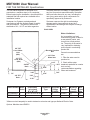
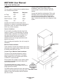
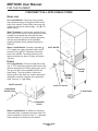
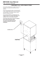
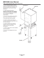
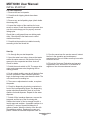
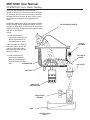
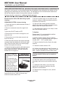
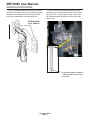
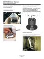
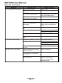
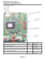
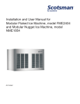
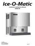
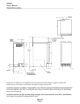
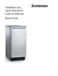
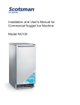
Installation and
User's Manual for
Ice Maker-Dispenser
Model MDT6N90
MDT6N90 User Manual
INTRODUCTION
To the owner or user: The service manual you are
reading is intended to provide you, and the
maintenance or service technician with the
information needed to install, start up, clean,
maintain, and service this ice maker-dispenser.
The MDT6 is a combination nugget ice maker and
countertop dispenser. A water station is standard.
FOR THE INSTALLER: Specifications ·
FOR THE INSTALLER · · · · · · · · ·
FOR THE PLUMBER · · · · · · · · · ·
FOR THE ELECTRICIAN · · · · · · · ·
FOR THE INSTALLER: Final Check List
INITIAL START UP · · · · · · · · · · ·
OPERATION: Ice or Water Vending · ·
DISPENSE AREA SANITATION · · · ·
CLEANING and SANITIZING · · · · · ·
SENSOR MAINTENANCE · · · · · · ·
BEARING MAINTENANCE · · · · · · ·
SERVICE DIAGNOSIS · · · · · · · · ·
CONTROL SYSTEM DIAGNOSTICS ·
·
·
·
·
·
·
·
·
·
·
·
·
·
The ice making section is equipped with the
following features: electronic controls for bin level
and low water; thermostatic expansion valve; front
service for most components; and R-404A
refrigerant. The ice dispensing section is a
seamless plastic storage bin, with a stainless steel
ice agitator at the bottom to sweep the ice into the
dispensing chute.
Table of Contents
· · · · · · · · · · ·
· · · · · · · · · · ·
· · · · · · · · · · ·
· · · · · · · · · · ·
· · · · · · · · · · ·
· · · · · · · · · · ·
· · · · · · · · · · ·
· · · · · · · · · · ·
· · · · · · · · · · ·
· · · · · · · · · · ·
· · · · · · · · · · ·
· · · · · · · · · · ·
· · · · · · · · · · ·
·
·
·
·
·
·
·
·
·
·
·
·
·
·
·
·
·
·
·
·
·
·
·
·
·
·
·
·
·
·
·
·
·
·
·
·
·
·
·
·
·
·
·
·
·
·
·
·
·
·
·
·
·
·
·
·
·
·
·
·
·
·
·
·
·
·
·
·
·
·
·
·
·
·
·
·
·
·
·
·
·
·
·
·
·
·
·
·
·
·
·
·
·
·
·
·
·
·
·
·
·
·
·
·
·
·
·
·
·
·
·
·
·
·
·
·
·
·
·
·
·
·
·
·
·
·
·
·
·
·
·
·
·
·
·
·
·
·
·
·
·
·
·
·
·
·
·
·
·
·
·
·
·
·
·
·
·
·
·
·
·
·
·
·
·
·
·
·
·
·
·
·
·
·
·
·
·
·
·
·
·
·
·
·
·
·
·
·
·
·
·
·
·
·
·
·
·
·
·
·
·
·
·
·
·
·
·
·
·
·
·
·
·
·
·
·
·
·
·
·
·
Page 2
Page 3
Page 4
Page 5
Page 6
Page 7
Page 8
Page 9
Page 10
Page 11
Page 12
Page 13
Page 14
Note this symbol when it appears.
It marks a possible hazard.
November 2008
Page 1
MDT6N90 User Manual
FOR THE INSTALLER: Specifications
This ice maker-dispenser is designed to be
mounted on a machine stand, or a countertop.
Before beginning the installation, check that all the
materials and kits required are available at the
installation location.
Scotsman assumes no liability or responsibility of
any kind for products manufactured by Scotsman
that have been altered in any way, including the
use of any parts and/or other components not
specifically approved by Scotsman.
Scotsman Ice Systems are designed and
manufactured with the highest regard for safety
and performance. They meet or exceed the
standards of U.L., N.S.F. and other agencies.
Scotsman reserves the right to make design
changes and/or improvements at any time.
Specifications and designs are subject to change
without notice.
BACK VIEW
Water Limitations:
3/8" FPT
Cond. Water
Inlet
(W/C)
Electrical Junction
Box
3/8" Flare
Water Inlet
1/2" FPT
Cond. Drain
(W/C)
6.63"
3/4 FPT
Drain
4.63"
3.84"
.75"
2.63"
3/4" FPT
Drain
Model Number Model
Series
MDT6N90AS-1 J
MDT6N90WS-1 J
An ice machine is a food
manufacturing plant; it takes in
a raw material, water, and
turns it into a food product,
ice. The purity of the water is
very important in obtaining
pure ice and in maximizing
product life.
General recommendations
are:
1. Filter the water used to
produce ice.
2. Check with a water
12.5" treatment specialist for a water
test, and any
recommendations regarding
filters and treatment.
7.93"
5.59"
17.59"
Dimensions
Condenser Refrigerant
Basic
Minimum
(w/o stand)
Type
Charge
Electrical
Circuit
H" x W" x D"
(R-404A)
Ampacity*
45.74 x 35.18 x 29.26 Air
32
115/60/1
18.1
same
Water
19
same
16.5
*Minimum circuit ampacity is used to determine wire size and type per National Electric Code.
Options: Machine stand DMS31.
August 2010
Page 2
Max.
Fuse
Size
25
20
MDT6N90 User Manual
FOR THE INSTALLER
Location
This ice system is designed to be installed indoors,
in a controlled environment.
Minimum
Maximum
0
50 F.
100 F.
Water Temp
0
40 F.
1000F.
Water Pressure
20 psi
80 psi
Voltage
104
126
Air Temp
0
In both counter top and machine stand
installations, wipe off and neatly smooth any
excess sealant. Level the machine stand and
cabinet.
Unpack and install the sink brackets. Fit the sink
assembly onto the two sink brackets, and press
onto the bead of sealant. Wipe off and neatly
smooth any excess sealant from under the sink
edge. Connect the sink drain to the dispenser drain
system.
Operating the machine outside of the above
limitations, or outdoors, is potentially damaging to
the machine; also it is misuse of the machine
which may void the warranty.
Service Limitations
Do not install in a location where the top of the
machine is within 6" of a fixed ceiling. Air cooled
models require a minimum of 6 inches to the left
and right of the machine for air circulation. It is
important that the machine be installed in a
location where it has enough space above and
behind it for service.
After uncrating and inspection, the unit is ready for
installation.
Airflow
Machine Stand Installation
Tip the stand on its back and install the legs, return
the stand to the upright position. Adjust leg levelers
so that the stand does not “rock”.
Counter Top or Machine Stand Installation
The base of the icemaker-dispenser must be
sealed to the object it rests upon. Food grade
silastic sealant such as Scotsman part number
19-0529-01 is recommended.
Place a bead of the sealant on the machine stand
or counter top to match the outside edge of the
cabinet base and sink.
SEAL
ICEMAKERDISPENSER TO
THE COUNTER
TOP OR
The DMS machine stand has holes in the top that MACHINE STAND
The icemaker-dispenser is heavy: use of a
mechanical hoist is recommended to lift it to the
height required to install it.
match up with threaded holes in the base of the
machine. Secure the machine stand to the base
with 4 5/16" bolts.
November 2008
Page 3
MDT6N90 User Manual
FOR THE PLUMBER
CONFORM TO ALL APPLICABLE CODES
Water Inlet
Air Cooled Models: Connect a clean, potable
and cold water supply to the 3 8” male flare at the
back of the cabinet. Install a hand valve near the
machine to control the water supply. Use 3 8” O.D.
copper tubing.
Water Treatment: In most areas, a water filter of
some type will be useful. In areas where the water
is highly concentrated with minerals the water
should be tested by a water treatment specialist,
and the recommendations of the specialist
regarding filtration and/or treatment should be
followed.
Water Cooled Models: Connect a separate 3 8”
O.D. copper line, with a separate hand valve to
control it, to the 3 8” FPT condenser inlet at the
back of the cabinet. The water pressure to all
lines must always be above 20 psig, and below
120 psig.
INLET WATER
Drains
Air Cooled Models: Connect a drain tube to the
one ¾” FPT drain fitting (plastic) at the back of the
cabinet, the drain line is of the gravity type, and ¼
inch per foot fall is an acceptable pitch for the
drain tubing. There should be a vent at the
highest point of the drain line, and the ideal drain
receptacle would be a trapped and vented floor
drain. Use only ¾” rigid tubing.
WATER COOLED
VENTED
DRAIN
OPTIONAL
WATER
FILTER
SHUT OFF VALVE
CONDENSER
WATER INLET
FLOOR DRAIN
CONDENSER
DRAIN
Water Cooled Models: In addition to the above
mentioned drain, a separate condenser drain line
must be installed. Connect it to the ½ " condenser
drain connection at the back of the cabinet.
November 2008
Page 4
MDT6N90 User Manual
FOR THE ELECTRICIAN
CONFORM TO ALL APPLICABLE CODES
Connect the electrical power supply for the unit to
the wires in the junction box at the rear of the
machine.
Check the nameplate (located on the back panel)
for the voltage requirements, and for the minimum
circuit ampacity. The machine requires a solid
chassis to earth ground wire.
The ice maker should be connected to its own
electrical circuit so it would be individually fused.
Voltage variation must remain within design
limitations, even under starting conditions.
All external wiring must conform to national,
state, and local electrical codes.
The use of a licensed electrician is
required to perform the electrical
installation.
POWER SUPPLY
ELECTRICAL
CONNECTION
November 2008
Page 5
MDT6N90 User Manual
FOR THE INSTALLER: Final Check List
1. Is the icemaker-dispenser installed
indoors, in a location where the air and
water temperatures are controlled, and
where they do not go beyond design
limitations?
ELECTRICAL?
2. is there an electrical service
disconnect within sight of the installed
machine? Is the machine on a separate
circuit? Has the voltage been checked
and compared to nameplate
requirements?
3. Have all of the plumbing connections
been made and checked for leaks?
4. Has the machine been leveled?
5. Is there a minimum of 6 inches of
clearance at the left and right sides of an
air cooled machine?
6. Is there a minimum of 6 inches of
clearance at the top and back of the
machine for service and utility
connections?
7. Is there a water shut off valve installed
near the machine?
8. Have all of the shipping blocks been
removed?
WATER
INLET?
DRAINS?
November 2008
Page 6
LEVELED?
MDT6N90 User Manual
INITIAL START UP
Pre Start Inspection
1. Remove the two front panels.
2. Check that all shipping blocks have been
removed.
3. Remove any and all packing tape (check inside
the storage bin).
4. Inspect the interior of the machine for loose
screws or wires. Check the solenoid operated door
over the ice discharge port for properly secured
linkage pins.
Check that no refrigerant lines are rubbing each
other. Check that the fan blade on air cooled
models turns freely.
5. Check that the machine is installed correctly
according to the final check list.
Start Up
1. Go through the pre start inspection.
2. Open the water hand valve, observe that water
enters the water reservoir, fills the tube from the
reservoir to the evaporator and then shuts off.
Check for leaks.
3. Switch the mode switch to ON. The auger drive
motor and compressor start, beginning the ice
making process.
8. Give the owner/user the service manual, instruct
him/her in the operation and maintenance
requirements of the unit. Make sure they know who
to call for service.
9. Fill out the Customer Evaluation and warranty
Registration form, and mail it in to Scotsman or
register on line at www.scotsman-ice.com.
4. On air cooled models, warm air will begin to flow
from the condenser. Water cooled models will
begin to discharge warm water down the drain.The
unit should soon be making ice.
5. There are no adjustments to make, so replace
the panels.
6. Check ice dispensing by placing a container in
front of the ice dispensing sensor, the dispensing
system should activate and if there is ice in the
machine it should dispense. Repeat for the water
dispense.
7. Switch off the icemaker-dispenser, remove the
top panel and the top of the ice storage bin.
Sanitize the interior of the ice storage bin with a
locally approved sanitizer. A possible sanitizer is a
mixture of 1 ounce of household bleach to 2
gallons of water. Wash the interior of the bin with
the sanitizing solution. Replace all covers and
panels. Switch the icemaker-dispenser back on.
September 2013
Page 7
MDT6N90 User Manual
OPERATION: Ice or Water Vending
When the ice dispensing sensor detects a
container in front of it, the control board connects
an electrical circuit to the ice chute door solenoid
causing the ice chute door to open. At the same
time power is connected to the agitator drive
motor.
Dispensing takes place when the agitator sweeps
the ice through the ice dispensing chute: ice will
continue to discharge out this chute as long as the
agitator is turning. It stops when the agitator stops
and the ice chute door
closes.
ICE DISCHARGE CHUTE
· If the user does not
remove the container, ice
will be dispensed for 60
seconds and then stop.
If the container is in front of
the water sensor on the left
side, the inlet water valve
will open and water will flow
into the container.
DOOR
SOLENOID
· If the user does not
ICE CHUTE
DOOR
remove the container
water will be dispensed
for 90 seconds and then
stop.
STORAGE BIN
ICE CHUTE
AGITATOR
AGITATOR
DRIVE MOTOR
TOUCH FREE
SENSOR
SINK
November 2008
Page 8
MDT6N90 User Manual
DISPENSE AREA SANITATION
The dispense area; spouts, sink, grill and splash
panel will need periodic cleaning and maintenance.
1. The ice chute may be pulled down to remove it
from the ice dispenser. Wash and sanitize it.
2. The sink grill may be removed for washing and
sanitizing.
3. The sink should be flushed with hot water and
wiped clean with sanitizer.
4. The splash panel requires special attention to
clean it.
· Push and release the Splash Panel Cleaning
switch located to the left of the water spout.
This disables the Touch Free sensors so the
splash panel may be cleaned without vending
ice and/or water.
· Wash the splash panel and wipe with with
sanitizer.
Re-push the clean switch or allow 2 minutes to
pass for the Touch Free system to reset.
Splash Panel
Cleaning
Switch
November 2008
Page 9
MDT6N90 User Manual
CLEANING and SANITIZING
It is the USER’S RESPONSIBILITY to see that the unit is properly maintained. It is always preferable, and
less costly in the long run, to avoid possible down time by keeping it clean; adjusting it as needed; and by
replacing worn parts before they can cause failure. The following is a list of recommended maintenance
that will help keep the machine running with a minimum of problems.
Cleaning should be scheduled at a minimum of twice per year.
Electrical power will be ON when doing in place
cleaning.
ICEMAKING SYSTEM: In place cleaning
9. As the ice maker begins to use water from the
reservoir, continue to add more cleaning solution
to maintain a full reservoir.
1. Check and clean any water treatment devices, if
any are installed.
10. After all of the cleaning solution has been
added to the reservoir, and the reservoir is nearly
empty, switch the master switch to OFF.
2. Remove screws and remove the upper front
panel.
11. After draining the reservoir, as in step 6, wash
and rinse the water reservoir.
3. Move the ON-OFF switch to OFF.
To Sanitize:
4. Remove the cover to the ice storage bin, and
remove the ice.
Repeat steps 8-11, except substitute sanitizer
solution for the cleaning solution.
5. Remove the cover to the water reservoir and
block the float up.
A possible sanitizer solution may be made by
mixing 1 ounce of household bleach and 2 gallons
of warm (95oF. - 115oF.) potable water.
6. Drain the water reservoir and freezer assembly
using the drain tube attached to the freezer water
inlet. Return the drain tube to its normal upright
position and replace the end cap.
7. Prepare the cleaning solution: Mix eight ounces
of Scotsman Ice Machine Scale Remover with
three quarts of hot water. The water should be
between 90-115 degrees F.
12. Remove the block from the float in the water
reservoir.
13. Switch the master switch to ON
14. Continue ice making for at least 15 minutes, to
flush out any cleaning solution. Check ice for acid
taste - continue icemaking until ice tastes sweet.
DO NOT USE any ice produced from the
cleaning solution. Be sure no ice remains in
the bin.
Scotsman Ice Machine
Scale Remover contains
acids.
These compounds may
cause burns. If swallowed,
DO NOT induce vomiting.
Give large amounts of
water or milk. Call
Physician immediately. In
case of external contact,
flush with water. Keep out
of the reach of children.
15. Remove all ice from the storage bin.
16. Add warm water to the ice storage bin and
thoroughly wash and rinse all surfaces within the
bin.
17. Sanitize the bin interior, cover, door and
agitator with an approved sanitizer using the
directions for that sanitizer.
8. Slowly pour the cleaning solution into the water
reservoir until it is full. Wait 15 minutes, then
switch the master switch to ON.
18. Replace the ice storage bin cover, and the
front panel.
November 2008
Page 10
MDT6N90 User Manual
SENSOR MAINTENANCE
1. The ice machine senses water level by a probe
located in the water reservoir. At least twice a year,
the probe should be removed from the reservoir,
and the tip wiped clean of mineral build-up.
2. The bin control uses devices that sense light,
therefore they must be kept clean enough so that
they can “see”. At least twice a year, remove the
bin control sensors from the ice chute, and wipe
them clean.
SLIDE SENSORS
UP TO REMOVE
Clean the Probe's Tip with ice
machine cleaner and a clean,
soft cloth.
November 2008
Page 11
MDT6N90 User Manual
BEARING MAINTENANCE
The bearing in the breaker should also be checked
at least two times per year.
A. Check the bearing by:
Inspect the bearing. There should be plenty of
grease and it should not appear watery or
contaminated.
If the bearing needs grease, inject grease into the
bearing using Scotsman grease needle pn
02-3559-01 and Scotsman bearing grease
cartridge, pn A36808-001. Be sure to inject grease
evenly and thoroughly.
· removing the ice chute cover
· unscrewing the ice sweep
Ice Sweep
Bearing
Needle, pn
02-3559-01
· removing the water shed
· unscrewing the breaker cover.
Breaker
Cover
Solenoid Linkage Check
Confirm that the linkage pins at the solenoid door
are properly secured with cotter pins.
Off
Check Cotter Pins (Circled)
November 2009
Page 12
MDT6N90 User Manual
SERVICE DIAGNOSIS
Symptom
No ice is made, nothing operates
No ice, auger motor is turning
Unit makes ice, but very slowly.
Possible Cause
Unit off due to no power
Unit off due to master switch in
OFF position.
Unit off due to low water level.
Probable Correction
Restore Power
Switch master switch to ON.
Check water supply, filter, float
valve. Correct water supply.
Check/clean ice level sensors.
Unit off due to ice level sensors
(photo-electric eyes) blocked.
Unit off due to scale on water level Clean water level sensor.
sensor.
Unit off due to high pressure
Check for water interruption (water
control open.
cooled) or fan motor failure (air
cooled).
Auger motor hums but does not
Auger can’t turn.
turn.
No power to circuit board.
Check harness
HI pressure cut out open
Circuit Board gear motor relay will Check, replace board
not close
Water level or ice level sensor
Check, replace sensor
failed.
Compressor contactor coil is open Check/replace contactor
Compressor will not start
Check start capacitor.
Check start relay
Check compressor windings
Circuit board compressor relay will Check, replace board
not close.
High discharge pressure because Clean the condenser.
of a dirty condenser
Clean the water system
Low capacity because the auger
and evaporator are coated with
mineral scale
Low suction pressure due to low
Locate leak. Recover refrigerant,
refrigerant charge
repair leak, replace dryer,
evacuate and weigh in the
nameplate charge
November 2008
Page 13
MDT6N90 User Manual
CONTROL SYSTEM DIAGNOSTICS
The control system consists of:
· Control Board
· Water Sensor
· Ice Sensors
· Vending Sensors
1, Power Light
2, Bin Empty
Light
3, Delay Timer
Light
4, No Water
Light
Explanation of Indicator Light
On at all times when the master switch is ON and machine is
connected to electrical power.
On when ice level is low (unit making ice).
Normal 6 minute off/delay start. To prevent short cycling, the
machine will not restart after any shut off (except power to the
board) until 6 minutes have passed.
On when water level is low in the reservoir.
November 2008
Page 14
Position On
Board
1
2
3
4
Name and Meaning of
Light or Reset
Power,
ON = Normal
Bin Empty,
ON = Needs Ice
Off Timer,
ON = Unit cycling off
No Water,
ON = Trouble
SCOTSMAN ICE SYSTEMS
775 Corporate Woods Parkway, Vernon Hills, IL 60061
800-533-6006
www.scotsman-ice.com
17-3283-01