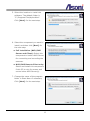
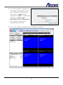
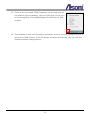
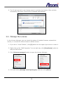
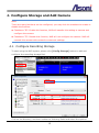
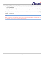
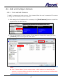
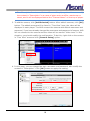
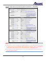
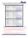
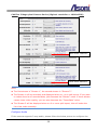
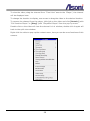
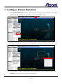
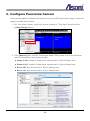
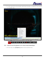
1
All-In-One IP Video Management Software APV7000-Pro User’s Guide Date: 8/20/2012 Software Version: V736 Content Content.................................................................................................................. 1 1. Preface ............................................................................................................. 2 2. System Requirements ....................................................................................... 3 3. Software Installation ........................................................................................ 5 3.1. Activate the License ...................................................................................... 10 3.2. Manage the License....................................................................................... 12 4. Configure Storage and Add Camera ................................................................ 15 4.1. Configure Recording Storage .......................................................................... 15 4.2. Add and Configure Camera ............................................................................ 17 4.2.1. Find and Add Camera............................................................................ 17 4.2.2. Adjust Video, Audio and Other Functions of Camera.................................. 19 5. Live View ........................................................................................................ 28 5.1. The Live View Screen .................................................................................... 28 6. Configure Recording Function ......................................................................... 31 6.1. Fulltime Recording ........................................................................................ 31 6.2. Scheduled Recording ..................................................................................... 32 6.3. Event Recording ........................................................................................... 33 7. Configure Motion Detection............................................................................. 34 8. Configure Panorama Camera .......................................................................... 36 9. Playback ......................................................................................................... 40 9.1. Playback the Concurrent Channel .................................................................... 40 9.2. Select and Playback from Recorded Database ................................................... 41 9.3. Export the Recorded Data .............................................................................. 44 1 1. Preface APV7000 series is an all-in-one IP video management software, user can use single software and related license code to do the following functions: NVR Server: Connect and record the video/audio of IP Cameras and IP Video Servers. The NVR server is working under background after Windows is startup. NVR Client: The console for access and control the local or remote NVR server, provides live-view, playback, event notification and configuration. CMS Server: If a NVR server (the primary NVR server) connects to multiple NVR servers simultaneously, it is called CMS (Central Management System) architecture. This primary NVR server is sometimes referred to as the "CMS server". The CMS server is allowed to perform live-view, playback, event notification and configuration across multiple NVR servers at the same time. The CMS server is working under background after Windows is startup. CMS Client: The console for access and control the local or remote CMS server, provides live-view, playback, event notify and configuration. Panorama Function: Beside the normal camera, this software also supports panorama (fisheye) camera, provides multiple panorama view modes in live and playback video. APV7000 series supports vary ways to record the video, including normal recording, schedule recording, motion-triggered recording, alarm-triggered recording and manual recording. In addition, E-Map and Multi-Monitor are the built-in functions to make this recording software handy. Through activating the remote access function, this software provides fully remote accessed and controlled by CMS, NVR Client program and IE web browser; also provides live-view video for iPhone and other 3G mobile phone. Note: To keep using this software without charge, the PC must connect to Internet always, once our license-server can’t detect your PC through Internet, the software will not work until the PC connects to Internet again. 2 2. System Requirements The following lists the recommended PC specification. Note: The PC performance, brand of camera, camera’s resolution and FPS, will affect the maximum simultaneous live-view channels. Connecting Cameras 1~9 channels of IP Cameras/Video servers CPU: Intel I3-2100 3.1GHz RAM: 4GB Display Card: Independent display card with 1GB RAM on board, ATI or nVidia chipset is recommended, such as ATI-5450 or above Recording Hard Disk Drive PC Specification Internal: SATA II/III 7200rpm, File System: NTFS External: DAS (Direct Attached Storage) connected via eSATA or USB2.0/3.0 interface Network: NAS (Network Attached Storage) connected via iSCSI interface Operating System: Windows 7 Professional or above Codec: Must install “Intel Media SDK” into Windows Resolution Bitrate Frame Rate Simultaneous Recording Channels CIF (320x240) D1 (720x480) 1.3M (1280x1024) 2M (1600x1200) H.264 H.264 H.264 H.264 512Kbps (CBR) 1Mbps (CBR) 1.5Mbps (CBR) 2Mbps (CBR) 30 FPS 30 FPS 10 FPS 15 FPS Up to 9 CH Up to 9 CH Up to 9 CH Up to 9 CH Up to 9 CH Up to 9 CH Up to 9 CH Up to 9 CH Up to 9 CH Up to 9 CH Up to 9 CH Up to 6 CH Simultaneous Live-View Channels (with Asoni H.264 Camera) Simultaneous Live-View Channels (with other brand H.264 Camera) 3 Connecting Cameras 10~64 channels of IP Cameras/Video servers CPU: Intel I5-3550 (Ivy Bridge) 3.3GHz RAM: 4GB Display Card: Independent display card with 2GB RAM on board, ATI or nVidia chipset is recommended, such as ATI-5450 or above Recording Hard Disk Drive PC Specification Internal: SATA II/III 7200rpm, File System: NTFS External: DAS (Direct Attached Storage) connected via eSATA or USB3.0 interface Network: NAS (Network Attached Storage) connected via iSCSI interface Operating System: Windows 7 Professional or above Codec: Must install “Intel Media SDK” into Windows Resolution Bitrate Frame Rate Simultaneous Recording Channels CIF (320x240) D1 (720x480) 1.3M (1280x1024) 2M (1600x1200) H.264 H.264 H.264 H.264 512Kbps (CBR) 1Mbps (CBR) 1.5Mbps (CBR) 2Mbps (CBR) 30 FPS 30 FPS 10 FPS 15 FPS Up to 64 CH Up to 64 CH Up to 64 CH Up to 64 CH Up to 64 CH Up to 64 CH Up to 64 CH Up to 64 CH Up to 36 CH Up to 25 CH Up to 20 CH Up to 14 CH Simultaneous Live-View Channels (with Asoni H.264 Camera) Simultaneous Live-View Channels (with other brand H.264 Camera) 4 3. Software Installation 1. After receive the software package, unzip it and then double-click on [APV7000-Pro_Vxxx.exe] to start the installation. 2. Select the language you would like to use. 3. Click [Next] button for the next step. 4. Click and select [I accept the agreement] option under the License Agreement, and then click [Next] button for the next step. 5 5. Select the location to install the software. The default folder is "C:\Program Files\AplusView". Click [Next] for the next step. 6. Select the component you want to install, and then click [Next] for the next step. Full installation (NVR/CMS Server and Client): Select this component to build a NVR Server for connecting and recording the cameras. NVR/CMS Remote Client only: Select and install this component if this PC is only for access and control other NVR Server(s). 7. Change the name of the program folder in Start Menu if necessary. Click [Next] for the next step. 6 8. Check the settings and then click [Install] to start copy the necessary files into PC. 9. After the copy process, the software will automatically request the “Demo” license through Internet, click [Next] for the next step. 10. Click [Finish] to complete the installation. 7 11. The “Local Console” interface will be started automatically. In the login window, the default login user name is “admin” and password is “1234”. If enable the checkbox of [Save login information] and [Auto login], the console will be opened automatically next time. 12. The “Local Console” interface will be displayed as below: 8 13. There is an icon called “NVR Organizer” on the task tray on the bottom-right of desktop, you can right-click on the icon to list the options, and enable/disable the NVR server and console. 14. This software is now running under evaluation version, you can manage up to 8 IP cameras or NVR servers. If the PC always connects to Internet, you can use this software without charge forever. 9 3.1. Activate the License In the APV7000 system, there are two types of license: Online license: This type of license requires periodic Internet check of license validity. It allows users to transfer license from one computer to another, as long as the maximum concurrent license does not exceed the purchased ones. In most scenarios, this offers greatest flexibility, highest cost efficiency, and minimum risk. To use the online license, the NVR server will need unrestricted access to the Internet to use this license. Please note however, using this license means you will need Internet even in normal operation, as License Manager will check in the background periodically for license validation. Offline license: This type of license does not require Internet when normal operation. However it needs to be "Bound" to a specific computer. The operation to bind a license to a computer is called "Commit". If you committed a license to a computer, it became fused to that specific computer state (including its system and the underlying hardware). If you change the underlying system or hardware, you risk losing the license. It is generally recommended unless situation is required, user should avoid using offline license and choose the online one. Even if offline scenario is required, user should start from using online license. After a period of stable running, user can always convert online license directly to offline license through the process of committing. 1. If you have purchased a license code, click [X] button on the upper-right corner to close the “Local Console”, and then follow the next steps to active the license. 2. Right-click on “NVR Organizer” icon, click [Deactivate] to stop the NVR server. 3. Click [License manager] option to open the License Manager. 10 4. Click and select [Install package online. The computer must have access to internet]. Click [Next]. 5. Input the license code (Purchase code) and the type of package, and then input the quantity of cameras will be access by this computer, and then click [Next]. There are 3 types of packages: "pro": This means the Professional edition. "pano": This means the Panorama edition. "ipr": This means the Intelligent edition. Note: The desired quantity must not exceed the remaining purchased quantity. Do Not check the "Commit to current computer" box, keep this license as an Online license. After ensure the NVR system works properly, you can always convert an Online license to an Offline one later. 11 6. The PC will now link to our license-server to activate the license. After activate successfully, the demo license will be suspend automatically. 3.2. Manage the License In the License Manager, you can check the status of installed licenses, suspend the license, or convert the online license to offline license. 1. If you are in “Local Console”, click [X] button on the upper-right corner to close it. 2. Right-click on the “NVR Organizer” icon on task tray, click [Deactivate] option to stop the NVR server. 3. Click [License manager] option to open the License Manager. 4. Click and select [Manage install packages], and then click [Next]. 12 5. The following screen will appear and list the installed license packages. License status Authorized packages Below explains license status: "OK ": This online license works correctly. "NEW": This is a newly installed license. "BOUND": This is an offline (committed) license which works correctly. "UNKNOWN": This license is currently working (and is previously known working). But due to some factors (such as lacking Internet connection or exceeding maximum concurrent license), it might soon be invalidated. "FAIL": This license is invalidated, mostly likely due to license check failure, or license revoked at License-server side. "INVALID": This license is invalidated, mostly likely due to computer system has been changed. 13 6. If you want to convert an online license to offline license, right-click on that license and select [Commit to current computer] to perform the commit operation. You'll need Internet connection to perform this operation. 7. After commit, the status of the license will be displayed as “BOUND”. Click [X] on upper-right to close the License Manager. 14 4. Configure Storage and Add Camera Note: There are many functions can be configured, you may click the checkbox to enable or disable the function: Checkbox=“”: Enable this function, NVR will transfer this setting to camera and configure the camera. Checkbox=“”: Disable this function, NVR will not configure the camera. NVR will connect this camera with camera’s concurrent settings. 4.1. Configure Recording Storage To start using the NVR system, please click [Config Storage] button to add and configure the recording storage first. Click on the directory, and then enable the following fields and select the options: 15 “Enable” field: Select “Yes”. It means this directory (folder) will be used for store the recorded data. “MaxSize_GB” field: Type in the maximum used storage size. The unit is GB (Giga byte). Configure the other directory if you want to use multiple storages. And then click [OK] to apply the settings. Note: When a directory is full, NVR will record into the next directory. When all directories are full, NVR will overwrite the directories automatically. 16 4.2. Add and Configure Camera 4.2.1. Find and Add Camera To add IP cameras and video servers, first, please follow the user’s manual of IP camera to assign the IP address of each camera. 1. After assign the IP address of all cameras, click [Find Cameras] button to add the cameras into the NVR server. 2. Click on the name to select camera. If you want to change the name, just click [Rename] button and type the new name. Note: The “Channel Name” is the unique name in NVR system for identifying the camera, it must be different between all cameras, and it cannot be modified after the camera has been added. 17 The “Description” can be modified in “Camera Setup” page later. You can modify the content in “Description” to a name of place such as office, warehouse or street, and it will be displayed behind the “Channel Name” on the top of player. 3. To add the camera, click [Add Selected] button. After add all cameras, click [OK] button. The added cameras will be listed in “Tree View” area, the video will be displayed in each player. The NVR connect the camera with default username and password, if you have already changed the username and password of camera, NVR will not connect to the camera and the video will be warned “Video Loss”. In this situation, you should modify the configuration. To do this, right-click on the camera in “Tree View” area and click [Camera Setup] option. 4. In this page, you can change the login username and password, also modify the content in “Description”. Click [OK] button to apply the setting. 18 4.2.2. Adjust Video, Audio and Other Functions of Camera After add the camera, you can adjust camera’s video, audio and enable the other functions. Right-click on the camera in “Tree View” area and click [Video Setup] option. This page provides the detailed configuration for camera. Enable Motion Detection and Digital I/O Function Click [Video] tab, and then enable the following fields and select the options. These settings will make NVR supports the motion detection and digital I/O of this camera. “MotionDetection” field: Select “Config+Capture”. “DIOProfile” field: Select “Auto”. 19 Enable PTZ Function If the camera supports PTZ function, click [Video] tab, and then enable the following fields and select the options. These settings will make NVR supports the PTZ functions of this camera. “UsePTZ” field: Select “4way”. “PresetNumber” field: Select “Auto”. Configure Video Format, Resolution, FPS …… Note: In NVR system, the “Video display” consumes many resource of PC. Higher resolution and frame rate consumes more resource. Our NVR uses “Dual Stream” technique to enhance the display performance in “Live View”. If the camera supports dual stream, you should enable both video stream. NVR will display the first stream (the higher resolution video) when on 1 or 4 split layout, and display the second stream (the lower resolution video) when on 9 or more split layout. NVR always record the video of first stream, the parameters of first stream will also affect the recorded data. Since NVR only records the first stream, it always (and only) play back the first stream (the higher resolution video) in “Playback” mode, more channels will consume more PC resource. Thus, you should not play back too many channels simultaneously. If the second stream is disabled, NVR will always display the first stream. 20 The video parameters of various camera series are different, to reach the best live-view performance, please follow the below picture to configure the settings. CAM6xx Full-HD Camera Series (Highest resolution = 1920x1080) Note: The Stream 1 will be recorded, and displayed when on 1 or 4 split layout. If you want to reduce the size of recorded data, just decrease the “Bitrate” value. If lower bitrate causes lower video quality, you can also decrease the “FrameRate” value. The Stream 2 will be displayed when on 9 or more split layout, this will make the live-view video smoothly. 21 CAM6xx 2 HD-720P Camera Series (Highest resolution = 1280x800) Note: The Stream 1 will be recorded, and displayed when on 1 or 4 split layout. If you want to reduce the size of recorded data, just decrease the “Bitrate” value. If lower bitrate causes lower video quality, you can also decrease the “FrameRate” value. The Stream 2 will be displayed when on 9 or more split layout, this will make the live-view video smoothly. 22 CAM6xx 2 Mega-pixel Camera Series (Highest resolution = 1600x1200) Note: The Stream 1 will be recorded, and displayed when on 1 or 4 split layout. If you want to reduce the size of recorded data, just decrease the “Bitrate” value. If lower bitrate causes lower video quality, you can also decrease the “FrameRate” value. The Stream 2 will be displayed when on 9 or more split layout, this will make the live-view video smoothly. 23 CAM6xx D1-Resolution Camera Series (Highest resolution = 720x480) Note: The Stream 1 will be recorded, and displayed when on 1 or 4 split layout. If you want to reduce the size of recorded data, just decrease the “Bitrate” value. If lower bitrate causes lower video quality, you can also decrease the “FrameRate” value. The Stream 2 will be displayed when on 9 or more split layout, this will make the live-view video smoothly. If you think the video quality of Stream 2 is not good, you can disable Stream 2 (uncheck “StreamingMode”), NVR will always display Stream 1. 24 CAM6xx VGA-Resolution Camera Series (Highest resolution = 640x480) Note: The Stream 1 will be recorded, and displayed when on 1 or 4 split layout. If you want to reduce the size of recorded data, just decrease the “Bitrate” value. If lower bitrate causes lower video quality, you can also decrease the “FrameRate” value. The Stream 2 will be displayed when on 9 or more split layout, this will make the live-view video smoothly. If you think the video quality of Stream 2 is not good, you can disable (uncheck “StreamingMode”) Stream 2, NVR will always display Stream 1. 25 CAM7xx 2 Mega-pixel Camera Series (Highest resolution = 1600x1200) Must select “Baseline” Must select “Baseline” Note: The first stream is “Stream 1”, the second stream is “Stream 3”. The Stream 1 will be recorded, and displayed when on 1 or 4 split layout. If you want to reduce the size of recorded data, just decrease the “Bitrate” value. If lower bitrate causes lower video quality, you can also decrease the “FrameRate” value. The Stream 3 will be displayed when on 9 or more split layout, this will make the live-view video smoothly. Configure Audio If the camera supports 2-way audio, please follow the below picture to configure the 26 settings, afterward, you can chatting to the camera through PC’s microphone. 27 5. Live View 5.1. The Live View Screen Click to “Playback” Click to “Synchronize Playback” Select channel layout Click to “Live View” Select page for view Connected cameras The “Player” The Channel Layout (Split-window) Click the “Layout Buttons” to change the layout (split-window). You can use multiple pages to display the channel, and each page can use different layout. 28 The “Player” There are two types of player, “Full-function Player” and “Simplified Player”: “Full-function Player”: This type of player allows for live-view and playback. There are channel name, description, function buttons and indicators on the top. It supports more functions in the pop-up menu when left-click on the video. “Simplified Player”: This type of player allows for live-view only. These two are “Full-function player”. Note, there is (P1.x) wording on the empty player. These eight are “Simplified player” Select Channels for Live View To view the video, drag the channel from “Tree View” area to the “Player”, the channel will be displayed now. To change the location to display, use mouse to drag the video to the desired location. To remove the channel from the player, left-click on the video for the pop-up menu, and then click [Detach] (with “Full-function Player”) or [Stop] (with “Simplified Player”). Operate the Live View Channel Channel name Description Chatting Audio Indicates it is under recording Indicates the camera is connecting Indicates it is in “Live View” or “Playback” OSD information 29 To view the video, drag the channel from “Tree View” area to the “Player”, the channel will be displayed now. To change the location to display, use mouse to drag the video to the desired location. To remove the channel from the player, left-click on the video and click [Detach] (with “Full-function Player” or [Stop] (with “Simplified Player” from the pop-up menu. Double-click on the video will view the channel in 1x1 window, double-click it again will back to the split-view window. Right-click the video to pop-up the context menu, here you can do more functions of this camera. 30 6. Configure Recording Function The NVR server provides various methods to record the video/audio of cameras. Fulltime Recording: Always record the video/audio of camera. Scheduled Recording: You can schedule the period for recording or not recording the camera. Each camera has its own schedule. Event Recording: When there is an event (including motion detection, alarm trigger, camera disconnected and PTZ control), the recording will be executed automatically. 6.1. Fulltime Recording 1. On “Live View” screen, right-click on the camera in “Tree View” area and click [Camera Setup] option. 2. In this page, if you want to fulltime record this camera, click and enable [Unconditional Recording] function. Click [OK] button to apply the setting. 31 6.2. Scheduled Recording 1. Right-click the video to pop-up the context menu, and click [Scheduled Recording Setup] option. 2. Click on the cell box to enable or disable the recording, blue means record and white means not record. To enable or disable a range of period, you can drag the a blue or white cell box and pull it to the direction, this will speed up the selection. 32 3. Click [OK] button to apply the settings for this camera. 6.3. Event Recording When there is an event (including motion detection, alarm trigger, camera disconnected and PTZ control), the recording will be executed automatically. 33 7. Configure Motion Detection 1. Click [Control Panel] button on the top to open a panel, select “Motion” from “New Object” list, a “Motion Function Object” will be added on video. 2. Drag the end point of “Motion Function Object” to the interested location and click “Region interest” to create the area for detecting, there are 3 areas can be detected. 3. The size and location of detect area can be adjusted. After create all areas, click [Save] button in panel to apply the settings. 34 There are two types of motion detection: Motion: Detect motion by IP camera itself. This type will not increase the loading of NVR. S-Motion: Software Motion. NVR will analyze the video content and detect the motion. It will more precise, but will increase the loading of NVR. It is recommended only used with important location. 35 8. Configure Panorama Camera If the camera equips a fisheye lens and wish to use the 360o panoramic image, follow the steps to enable this function. 1. On “Live View” screen, right-click on the camera in “Tree View” area and click [Video Setup] option. 2. Click [Record] tab, find the “Panorama Model” field, select one of the following options according to the camera model: Dome-1.25: Vandal or fixed dome camera with 1.25mm fisheye lens. Dome-1.47: Vandal or fixed dome camera with 1.47mm fisheye lens. Box-1.55: Box camera with 1.55mm fisheye lens. Box-1.47: Box camera with 1.47mm fisheye lens. 36 3. Back to “Live View” screen, click and select the video of camera, click [Control Panel] on the top to open a panel, select [Panorama] from “New Object” list, a “Panorama Function Object” will be added on video. 4. Drag the end point of “Panorama Function Object” to any location and click [Image Circle] to create the area for panoramic view. 37 5. The size and location of circle can be adjusted. After adjust the circle, click [Save] button in panel to apply the settings. 6. Back to “Live View” screen, right-click on the video and select [Panorama] -> [Pano+Free+Surround] option, the video will be turned to panoramic view. 38 7. You can scroll mouse-wheel to zoom-in/ zoom-out the video, drag the video to change the viewing location. 39 9. Playback 9.1. Playback the Concurrent Channel 1. On live-view, select “Std. timebar” on the top. 2. Move mouse on the time bar, the date/time of recorded data will be displayed, double-click to play the recorded video. 3. Use the playback buttons on the top to control the playback. 4. During the playback, the “>” symbol will display on the upper-left corner of video. Live-view Mode Playback Mode 40 5. You can right-click on the time bar, and select the option to change the time period of recorded video. 6. Click [LIVE] button on the top will back to live-view video. 9.2. Select and Playback from Recorded Database 1. On live-view, click [Playback] button on the top-left corner. 41 2. Click [Storage Map] button to open the “Storage Report” window, it is the recorded database. 3. On the left side, expand the channel -> date -> hour -> minute to find the recorded 42 data you wish to play, the video will be displayed on the bottom-right. 4. You can drag the playback video from “Storage Report” window to any “Full-function Player”, and then operate it in the split-window. The split-window allows display live-view and playback video simultaneously. 5. Use the playback buttons on the top to control the playback. 6. You can right-click on the time bar, and select the option to change the time period of recorded video. 7. To remove the playback channel from the player, left-click on the video for the pop-up menu, and then click [Detach]. 43 9.3. Export the Recorded Data 1. On the left side of “Storage Report” window, right-click on the channel which you wish to export the recorded data, and then click [Export Footage] option. 2. Set up the following options and then click [Download] button to export the recorded data. The channel(s) in left field will be exported The start and end time for export The format of the exported video Total file size of the exported video The location to save the exported video The prefix of the filename If the file size of exported video larger than the “Max File Size”, it will be split into multiple files. Click this button to start export process. 44 3. If you export the video with “AVI” format, you can use “Windows Media Player” to play it. 4. If you export the video with “XGV” format, the video quality is same as the original video, but the exported video can only be played by “APV7000-Player_Vxxx.exe” software. If you will send the exported video to others, remember also send “APV7000-Player_Vxxx.exe” software to them. 45