1
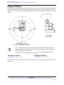
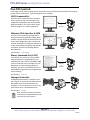
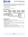
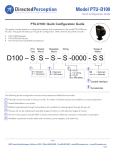
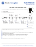
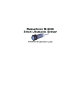
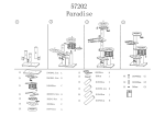
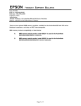
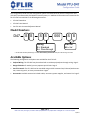
This Configuration Guide lists the configuration options and accessories for the PTU‐D47 pan‐tilt units (PTU‐D47) manufactured by FLIR Motion Control Systems, Inc. Additional information and instructions for the PTU‐D47 are available in the following documents:
•
PTU‐D47 Datasheet
•
PTU‐D47 User Manual
•
Pan‐Tilt Unit Command Reference Manual
ModelNumbers
D47
S S
S S
000
Wiring
S = Standard
A = Pass-through
S S
Pan/Tilt
SS = Std.*
* = SS denotes standard pan/tilt range of motion. Other lettering denotes alternate pan and/or tilt range of motion.
AvailableOptions
The following configuration and options are available for the PTU‐D47:
•
Payload Wiring: The PTU‐D47 may be ordered with or without payload pass‐through wiring. Page 2.
•
Range of Motion: If needed, you may request special limits. Page 3.
•
Pan‐Tilt Controls: The PTU‐D47 can be controlled using an ASCII command set, Ethernet/web connec‐
tion, external joystick, or binary command set. Page 4.
•
Accessories: Available accessories include cables, converters, power supplies, and starter kits. Page 5.
Page 1 of 7
890C Cowan Road, Burlingame, CA 94010 ● Office (650)692‐3900 ● Fax (650)692‐3900 ● [email protected] ● www.flir.com/MCS
03/2013
PTU‐D47 Series Configuration Guide
PayloadWiring
The D47 is available with pass‐through wiring to carry video, power, and other signals to the payload. Pass‐through wiring consists of flying leads that extend from the base of the PTU and are then wired externally to the payload. This option sim‐
plifies and streamlines external cabling.
Note: The PTU‐D47 is not available with a slip ring and is therefore incapable of continuous (360°) pan axis rotation.
Standard
The PTU‐D47 comes standard with no payload pass‐through wiring.
Part Number: D47‐SS‐SS‐000‐__
Base Connector
Pass-Throughs (flying leads)
Pass‐ThroughWiring
This option adds flying leads that allow you to route signals to the payload mounted on the PTU‐D47 as shown in the following table.
No
Pass‐Through
Flying
Leads
# of conductors
Passed Through
Power
0
2
Video
0
2
General
0
4
Total
0
8
RS‐232 Host Control
YES
YES
RS‐485 Host Control
YES
YES
Base Connector
Part Number: D47‐SS‐SA‐000‐__
Page 2 of 7
890C Cowan Road, Burlingame, CA 94010 ● Office (650)692‐3900 ● Fax (650)692‐3900 ● [email protected] ● www.flir.com/MCS
03/2013
PTU‐D47 Series Configuration Guide
RangeofMotion
The PTU‐D47 has the following standard factory pan and tilt axis limits. Factory limits define the range of motion allowed for an axis when limits are enabled, and that axis cannot travel beyond those limits.You may also order a PTU‐D47 with an optional slip ring that allows continuous 360° pan‐axis movement (see Page 3).
Note: You may special order a PTU‐D47 with custom hard stops installed and/or with custom bracket positioning, factory ranges of motion, etc. Please contact FLIR Motion Control Systems, Inc. for assistance.
Note: The PTU‐D47 supports tilt axis limits of ‐80° to +31° with extended range.
PanRangeOptions
TiltRangeOptions
Part Number: D47‐SS‐__‐000‐*_
Part Number: D47‐SS‐__‐000‐_*
The part number on your PTU‐D47 may vary as shown here to reflect any special‐ordered custom limits, stops, etc.
Page 3 of 7
890C Cowan Road, Burlingame, CA 94010 ● Office (650)692‐3900 ● Fax (650)692‐3900 ● [email protected] ● www.flir.com/MCS
03/2013
PTU‐D47 Series Configuration Guide
Pan‐TiltControls
PTUs support serial, Ethernet/web, binary, and joystick control interfaces that provide a wide range of system control architectures. The following options are available:
ASCIICommandSet
Your PTU can be controlled via the standard built‐in serial port (RS‐232 or RS‐485) using simple ASCII commands. (See the Command Reference Manual.) This can be done using a terminal program or a custom application.
RS-232
or
RS-485
Ethernet/WebInterface&GPM
Your PTU can be controlled via Ethernet/IP using the Geo‐Pointing Module (GPM), which includes a simple web‐based interface for PTU control and configuration from a mouse and entered commands. The GPM also allows PTU control using latitude, longitude, and altitude commands. (See the Geo Pointing Module Users Manual.)
Ethernet
Serial
GPM
Part Number: PTU‐DGPM
BinaryCommandSet(CAPI)
Your PTU can also accept binary commands using the optional C Language Binary Com‐
mand Set (PTU‐CPI), which is provided as ANSI C Source Code that you can compile into your application on most computing platforms (CPU/OS). The binary command format is rec‐
ommended for high‐performance applications such as tracking.
C API
RS-232
Or
RS-485
Part Number: PTU‐CPI
GamepadController
A USB gamepad controller is available to con‐
trol a single PTU and up to two VISCA‐compati‐
ble cameras that are connected to a host computer via a serial connection. The PTU Joy‐
stick Control utility is included with PTUs.
USB
SERIAL
Part Number: PT‐PSC
Note: Cameras should be connected to the host PC using a dedicated serial connection for each camera.
Page 4 of 7
890C Cowan Road, Burlingame, CA 94010 ● Office (650)692‐3900 ● Fax (650)692‐3900 ● [email protected] ● www.flir.com/MCS
03/2013
PTU‐D47 Series Configuration Guide
RuggedJoystick
A rugged joystick (PT‐DCJ) is available for direct control of the PTU with no computer required. The PT‐DCJ provides proportional joystick con‐
trol and other inputs via a 25’ connection cable. (Please see the PT‐DCJ Datasheet for details.)
RS-485
Part Number: PT‐DCJ (joystick)
PT‐DCJ‐CABLE (cable; required)
Accessories
The following accessories may be ordered for your PTU. These accessories simplify system prototyping and fielding.
BreakoutCables
The breakout cable connects to the 19‐pin base connector (MIL‐C‐26482) on the PTU and terminates to standard connec‐
tors for power, serial communication, and payload signals. The terminating connectors are: Power (DIN), 2x video (composite), RS‐232 (DB‐9, female), RS‐485 (RJ11), and payload pass‐through conductors. Length: 25’.
Part Number: PTU‐CAB‐25BO
PowerSupply
PTU power supply unit. 30VDC output, 110/220VAC input.
Dimensions: 3.44”W x2.01”Hx7.61”L.
Part Number: PTU‐APS‐30V‐NA (North America) or
PTU‐APS‐30V‐EC (Europe)
Note: Input voltages under 30V can reduce the maxi‐
mum speed of the unit by an amount that is propor‐
tional to the voltage difference.
StarterKit
The PTU starter kit includes one power supply (PTU‐APS‐30V), one 25’ breakout cable (PTU‐CAB‐25BO), and one USB to RS‐485 adapter cable (PTU‐CONV‐USB‐RS485).
Part Number: D47‐KIT‐S‐TR‐NA (North America) or
D47‐KIT‐S‐TR‐EC (Europe)
Note: Input voltages under 30V can reduce the maximum speed of the unit by an amount that is proportional to the voltage difference.
Page 5 of 7
890C Cowan Road, Burlingame, CA 94010 ● Office (650)692‐3900 ● Fax (650)692‐3900 ● [email protected] ● www.flir.com/MCS
03/2013
PTU‐D47 Series Configuration Guide
MatingConnector
Mating connector for the 19‐pin base and payload connectors (MIL‐C‐26482) PTU connectors. Use this to make custom PTU and/or payload cables.
Part Number: PTU‐CAB1‐19PMILC (19‐pin)
Note: Each PTU with a wiring option (PL01, PL02, or PL17) includes one (1) 19‐pin mating connector (PTU‐
CAB1‐19PMILC).
RS‐485toRS‐232Converter
Bi‐directional module that converts signals from RS‐232 to RS‐
485. Includes power supply, coupler, and cable.
Part Number: PTU‐CONV‐RS485C USBtoRS‐485AdapterCable
Cable that converts USB to RS‐485 serial connections.
Part Number: PTU‐CONV‐USB‐RS485
RuggedJoystickandCable
This rugged joystick allows PTU control without a host com‐
puter. Cable ordered separately.
Part Number: PT‐DCJ (joystick) and
PT‐DCJ‐CABLE (25’ DCJ connection cable)
Page 6 of 7
890C Cowan Road, Burlingame, CA 94010 ● Office (650)692‐3900 ● Fax (650)692‐3900 ● [email protected] ● www.flir.com/MCS
03/2013
PTU‐D47 Series Configuration Guide
Geo‐PointingModuleandEthernet/Web
Interface
The Geo‐Pointing Module (DGPM) provides both an Ethernet/
web interface for PTU control and geo‐pointing capalities. Please see the following documents for additional information:
•
Geo‐Pointing Module Datasheet
•
Geo‐Pointing Module User’s Manual
Part Number: PTU‐DGPM
ExtensionCables
An extension cable extends the length of a breakout cable. There is a male connector on one end and a female connector on the other. Available in 50’ and 100’ lengths.
Part Number: PTU‐CAB‐EXT‐50 (50’) or
PTU‐CAB‐EXT‐100 (100’)
Page 7 of 7
890C Cowan Road, Burlingame, CA 94010 ● Office (650)692‐3900 ● Fax (650)692‐3900 ● [email protected] ● www.flir.com/MCS
03/2013