1
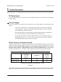
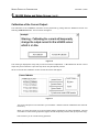
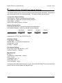
MASSA PRODUCTS CORPORATION November 1, 2004 This guide covers the installation and operation of the MassaSonic™ M-5000 Smart Ultrasonic Sensor and options: P/N 200504-501 M-5000/220 Full Sensor Kit which includes: p/n 300280-501 MassaSonic M-5000/220 Sm art Ultrasonic Sensor 220 kHz, 12° Beam p/n 7873-1 Locknuts (Qty 2) p/n 7875-1 User’s Manual p/n 200511-1 Mounting Bracket p/n 7868-1 Com m unications Converter p/n 7876-1 Installation & Setup Software (1 CD) P/N 200547-501 M-5000/95 Full Sensor Kit which includes: p/n 300306-501 MassaSonic M-5000/220 Sm art Ultrasonic Sensor 95 kHz, 12° Beam p/n 7873-1 Locknuts (Qty 2) p/n 7875-1 User’s Manual p/n 200511-1 Mounting Bracket p/n 7868-1 Com m unications Converter p/n 7876-1 Installation & Setup Software (1 CD) Windows® 3.1, 95, 98, 2000 or XP operating system is required to run the installation setup software. This document contains proprietary information which is protected by copyright. All rights are reserved. No part of this document may be photocopied, reproduced, or translated without the prior written consent of Massa Products Corporation. All specifications subject to change without notice. Warranty information may be found at the end of this operation guide. Copyright © 1998 by Massa Products Corporation. All rights reserved. MassaSonic is a Trademark of Massa Products Corporation. Manual Version: 5 Massa Products Corporation 280 Lincoln Street Hingham, MA 02043-1796 U.S.A. Tel: 781-749-4800 Toll Free: 800-962-7543 (USA) Web Site: www.massa.com Fax: 781-740-2045 E-mail: [email protected] MASSA PRODUCTS CORPORATION November 1, 2004 M-5000 Functional Block Diagram Figure 1 Installation & Operation Guide -iii- MassaSonic™ M-5000 Smart Ultrasonic Sensor MASSA PRODUCTS CORPORATION November 1, 2004 M-5000 Status and Setup Screen Figure 2 Installation & Operation Guide -iv- MassaSonic™ M-5000 Smart Ultrasonic Sensor MASSA PRODUCTS CORPORATION November 1, 2004 M-5000 Smart Ultrasonic Sensor Terminology Installation & Operation Guide -v- MassaSonic™ M-5000 Smart Ultrasonic Sensor MASSA PRODUCTS CORPORATION November 1, 2004 Table of Contents 1 Introduction .................................................................................................................................1 2 Quick Guide on Getting Started ...................................................................................2 3 Product Description DC Power Input ...................................................................................................................................3 Current Output .....................................................................................................................................3 Setpoint Outputs A and B ....................................................................................................................3 Echo Status Output ..............................................................................................................................4 Trigger I/O ............................................................................................................................................5 RS-485 Port .........................................................................................................................................5 Echo Detect Monitor Output ................................................................................................................6 LED Operation/Diagnostics .................................................................................................................6 4 Installing M-5000 Status and Setup Software .....................................................7 5 M-5000 Status and Setup Screen M-5000 Status .....................................................................................................................................8 ID Tag/User Description ......................................................................................................................9 Current Loop Output Settings ............................................................................................................10 Setpoint Output Settings ....................................................................................................................10 Echo Status Settings ...........................................................................................................................11 Sam pling Settings ..............................................................................................................................12 Message Area ....................................................................................................................................13 Calibrate Current Output .....................................................................................................................14 File Menu.............................................................................................................................................15 Save... Recall... Print... Exit Tools Menu ..........................................................................................................................................15 Calibrate Current Units Selection Menu ..........................................................................................................................15 Distance Tem perature Com m unications Port Selection Menu ..............................................................................................15 Tem perature Com pensation Selection Menu .....................................................................................15 Autom atic Preset Installation & Operation Guide -vi- MassaSonic™ M-5000 Smart Ultrasonic Sensor MASSA PRODUCTS CORPORATION November 1, 2004 Table of Contents (continued) Info Menu .............................................................................................................................................15 About This Program M-5000 Version 6 Standard Factory Default Programmed Settings ............................................16 7 Specifications .............................................................................................................................17 8 Troubleshooting .......................................................................................................................18 9 Terminology .................................................................................................................................19 10 Customer Support ................................................................................................................21 11 Appendix A: W ire Color Code of Standard M-5000 sensor ...............................................................................22 B: M-5000 Set Up Form .....................................................................................................................23 Warranty .............................................................................................................................................24 Installation & Operation Guide -vii- MassaSonic™ M-5000 Smart Ultrasonic Sensor MASSA PRODUCTS CORPORATION 1 November 1, 2004 Introduction The MassaSonic M-5000 Sm art Ultrasonic Sensor com bines Massa’s 50 years of experience in electro acoustics with state-of-the-art analog and m icroprocessor hardware and software design. The result is the m ost versatile, easiest to use ultrasonic sensor on the m arket. Operation: The M-5000 generates a high frequency ultrasonic pulse, m easures the tim e it takes for the echo to return and calculates the target distance. The tem perature effects on the speed of sound are com pensated for by m eans of an internal tem perature sensor. This distance inform ation is outputted as a 4 to 20 m a current (optionally program m able to 0 to 20m A). It is also outputted on an RS-485 com m unication port to be displayed on a PC screen controlled by an easy to use M-5000 Status and Setup program . Two independent Setpoint Outputs and an Echo Status Output allow m ulti-functional control. Key Features include: ! Analog & Setpoint Outputs ! Plug & Play Setup - No Targets Needed ! Software Set Span and Zero - No Pots or Pushbuttons, Tamperproof Settings ! Easy to Use Setup Software - W indows® 3.1, 95, 98, 2000, or XP ! Built-in Tem perature/Sound Speed Com pensation ! Up to 32 Sensors on RS-485 Multi-drop Loop MassaSonic™ M-5000/220 Smart Ultrasonic Sensor Full Sensor Kit (Installation & Operation Guide not shown) Installation & Operation Guide -1- MassaSonic™ M-5000 Smart Ultrasonic Sensor MASSA PRODUCTS CORPORATION 2 November 1, 2004 Quick Guide on Getting Started To becom e fam iliar with the operation and program m ing features of the M-5000, unpack the com ponents from the Full Sensor Kit and proceed as follows: 1. Secure the sensor onto the Mounting Bracket using the two m ounting nuts . 2. W ith the power supply off, wire the sensor’s red and black leads to a power supply as shown in Figure 1 (page iii). 3. W ire the sensor’s green lead to the A term inal and blue lead to the B term inal on the Com m unications Converter. At this tim e it is not necessary to connect the other wires. 4. Plug the Com m unications Converter into one of the serial ports of the PC (com 1, com 2, etc.). 5. Apply power to the sensor (12-28VDC). 6. Install the software into the PC as described on the supplied diskettes. 7. Execute the M-5000 program . 8. The first tim e the program is executed, the com m unications port used (step 4 above) m ust be selected. See Figure 7 (page 7). 9. After the program accesses the sensor, the Status and Setup Screen as shown in Figure 2 (page iv) will appear. 10. Point the M-5000 towards a target such as a wall. Make sure that the target is between 4" and 40" from the sensor and the front face of the M-5000 containing the transducer is aim ed perpendicular to the target. 11. Observe the “Average Distance” (located in the M-5000 Status Box). This is the distance between the target and the face of the sensor. 12. To change any of the M-5000 settings of the M-5000 Status and Setup Screen, m ove the m ouse pointer and click on the field to be m odified. After all changes have been m ade, click on the Program button. There is no lim it to the num ber of tim es the sensor can be reprogram m ed. 13. Turn off DC power and wire the rem aining connections as shown in Figure 1 (page iii). 14. The M-5000 sensor has a variety of different outputs and operating m odes, and should be optim ized for the best perform ance in each sensing application. Continue to read this Operation Guide for m ore detailed inform ation. quick guide quick guide quick guide Installation & Operation Guide -2- quick guide quick guide quick guide MassaSonic™ M-5000 Smart Ultrasonic Sensor MASSA PRODUCTS CORPORATION 3 November 1, 2004 Product Description Referring to Figure 1, the following describes the key functions and connection hook-ups for the M-5000: DC Power Input: The unit is powered from a 12 to 28Vdc source with approxim ately 60 m a current drain (not including the Current Output). Current Output: This is the analog current output which is proportional to the target distance. Program m ing options include: " 4-20 m A or 0-20 m A spans. Corresponding target distances m ust be within allowable sensing distances. Slope is based on the program m ed setting for the 4m A Distance (or 0m A Distance) and 20m A Distance. " After the 4m A Distance (or 0m A Distance) and the 20m A distance are program m ed, the current will be linear as the target distance varies between them . " If the target echo signal is lost (after a preset tim eout), the Current Output will go to a preselected value (0, 3.5, 4.0, 20 or 20.5 m A). See “No Echo Tim e Out” under the ECHO STATUS SETTING for tim eout inform ation. Setpoint Output A and Setpoint Output B: These are m ulti functional, independent open drain N-Channel MOSFET switches to ground (overvoltage and over-current protected). As shown in Figure 5, three zones are established by the user selecting a Close Setpoint Target Distance and a Far Setpoint Target Distance. The zones are defined as shown in Figure 5. Setpoint OUTPUT A & B can also be program m ed to ON or OFF when a “No Echo” condition occurs. The state of these outputs is based on the average target distance. Exam ple of one possible m atrix of the states of Setpoint Output A & Setpoint Output B. Close Zone < Close SP Distance M id Zone Far Zone > Far SP Distance Setpoint Output A OFF ON OFF Setpoint Output B OFF OFF ON Hysteresis for OUTPUT A and OUTPUT B [ 5% ] Figure 5 In the exam ple above, Setpoint Output A will turn ON (MOSFET switch closed to ground) when the target distance is in the Mid Zone between the Close and Far Setpoint Distances. Otherwise it will be OFF. Installation & Operation Guide -3- MassaSonic™ M-5000 Smart Ultrasonic Sensor MASSA PRODUCTS CORPORATION 3 November 1, 2004 Product Description (cont.) Setpoint Output A and Setpoint Output B: (cont.) In the Figure 5 exam ple, Setpoint Output B will turn ON when the target distance is greater than the Far Setpoint Distance. Hysteresis can be set as a percent of Close and Far Setpoint Distances (any valid value between 0% and 90%) to reduce the effects of noise or to im plem ent a control function. The M id Zone has program m ing states of ON or OFF and includes a 3 rd program m able state of No Change. Targets in this zone will not change state when in this zone. This feature creates a variable hysteresis around the CLOSE and FAR Setpoint Distances. Power up default for the M id Zone when program m ed to “No Change” is the state for the Close Zone. If both Setpoint Outputs are program m ed for NO CHANGE in the M id Zone, it is recom m ended that Hysteresis be set to 0%. This can be done by tem porarily changing a M id Zone to ON or OFF and setting the Hysteresis to 0%, then returning that M id Zone to NO CHANGE. If the other Setpoint OUTPUT has the M id Zone program m ed to either ON or OFF, then the hysteresis selection still applies for that OUTPUT only. In the exam ple shown in Figure 6, Setpoint Output A will not turn ON until target distance increases beyond the Far SP Distance. It will not turn O FF until the target distance decreases to less than the Close SP Distance. Close Zone < Close SP Distance M id Zone Far Zone > Far SP Distance Setpoint Output A OFF No Change ON Setpoint Output B ON OFF OFF Hysteresis for OUTPUT B [10% ] Figure 6 Echo Status Output: This is a third independent open drain N-Channel Mosfet to ground whose state can be program m ed to be either ON or OFF if no target is present. The num ber of echo sam ples which m ust be m issed consecutively to trigger this output to a “No Echo” state is program m able (see No Echo Tim eout under Echo Status Settings). Program m ing the “No Echo Tim e Out” to a value other than 1 will reduce the “No Echo” state caused by spurious m issing echos. NOTE: For this Echo Status Output ONLY, targets within approxim ately 0.2" of the m inim um sensing distance will cause the output to switch to the “No Echo” condition. The back panel LED will also indicate a loss of echo “Flash”. The M-5000 continuously m onitors itself for system integrity. Upon a fault, this Echo Status Output will go to its program m ed “No Echo” state. The error will be reported on the serial com m unications port. Som e errors m ay be restored by pressing the “Reset Error” button located in the m essage box (appears when a system error is detected). Installation & Operation Guide -4- MassaSonic™ M-5000 Smart Ultrasonic Sensor MASSA PRODUCTS CORPORATION 3 November 1, 2004 Product Description (cont.) Trigger I/O: There are 5Ttrigger Modes from sim ple, autom atic INTERNAL triggering, to triggering which assures that there will be no crosstalk in applications involving m ultiple M-5000s in close proxim ity to each other. Rem em ber, ultrasonic sensors are active; that is, one unit’s transm ission can be picked up by a second unit’s receiver (if within each others sensing beam ), giving false readings. Multiple units in the sam e area should be synchronized. The following describes the 5 Trigger Modes: Internal: The ultrasonic pulse is triggered by unsynchronized internal tim ing. The SAMPLE RATE is selected on the PC screen. In this m ode, the TRIGGER I/O line is an inactive input. Internal w ith TRIGGER Out: Sam e as INTERNAL, but with a TRIG GER pulse (0 to 5V, 150 :sec) appearing at the TRIGGER I/O line at the start of the ultrasonic transm it pulse. This can be used to TRIGGER a scope or other M-5000's. External: This line becom es an input for an external TRIGGER pulse (5V, 150 :sec). This allows the user to control when an ultrasonic transm it pulse is generated (sam ple rate). External w ith Delay: Sam e as EXTERNAL, except the ultrasonic pulse will be delayed an am ount specified by the user (this will appear next to the Trigger Mode field under the SAMPLING SETTING). This can be used in m ultiple M-5000 applications to prevent crosstalk. A “m aster” M-5000 will be program m ed for INTERNAL W ITH TRIGG ER O UT and connected to all other M-5000 TRIGGER I/O lines. Each of the “slave” M-5000's will be program m ed for EXTERNAL W ITH DELAY and have different DELAY TIMES selected. The sam ple rate of the m aster should allow all ultrasonic signals to subside before another “m aster” pulse is generated. M anual: If MANUAL trigger is selected, a TRIGGER button appears on the PC screen. Clicking the cursor on this button will produce a single ultrasonic pulse. No signal will appear on the TRIGGER I/O LINE. This should be used for diagnostics only. RS485 Port: Monitoring and program m ing the M-5000 Sm art Ultrasonic Sensor occurs through the RS-485 serial com m unications port. The advantages of an RS-485 based system are longer cable lengths (specified to 1,500 ft.) and wiring up to 32 sensors on just one pair of wires (m ulti-drop). This m ethod allows for access to all sensors from any convenient location. Since your com puter is an RS-232 based system , a converter between the two system s is required. The Massa Model M-5000/RS485 Interface Converter provides a m ethod of interfacing your com puter’s RS-232 based system to Massa Sm art Ultrasonic Sensor RS-485 based system . W ire the M-5000's RS485 green wire (A term inal) to the “A” input of the M-5000/RS485 and the RS485 blue wire to the “B” input of the M-5000/RS485. Plug the M-5000/RS485 to your PC’s serial 9 pin port. The M-5000 is now ready to com m unicate with the Massa Model M-5000/SW Status & Setup software program . M ulti-drop Operation: W hen you expect to wire m ore than one M-5000 on the sam e com m unications line, each sensor will have to be program m ed with its own unique ID Tag. To do this, you m ust place only one M-5000 sensor on line at a tim e. W ire the M-5000's RS485 green wire (A term inal) to the “A” Installation & Operation Guide -5- MassaSonic™ M-5000 Smart Ultrasonic Sensor MASSA PRODUCTS CORPORATION 3 November 1, 2004 Product Description (cont.) RS485 Port: (cont.) input of the M-5000/RS485 and the RS485 blue wire to the “B” input of the M-5000/RS485. Plug the M-5000/RS485 to your PC’s serial 9 pin port. Start the M-5000/SW Status and Setup software program by executing M5000.exe or the M-5000 icon. Edit the ID Tag field. Make note and label each sensor with the ID. See “Installing M-5000 Status & Setup Software” (Section 3) of this operation guide for m ore detail. Available ID Tag num bers are form 1 to 32. Repeat this exercise for all the sensors you plan on placing on the com m unications port. Once all the sensors contain their own unique ID Tag, then and only then can you wire all the sensors on the RS-485 com m unications port. The software will then allow you to m onitor and edit any sensor on-line. To m onitor another sensor, sim ply go to the ID Tag field and select another sensor by pulling down ID Tag Menu and highlight the sensor you prefer. W hen m ore than one sensor is on-line, the ID Tag field cannot be edited. Echo Detect Monitor Output: This output is a peak detection of the ultrasonic signals produced by the M-5000. It includes the transm it burst at the beginning of the waveform followed by the reflected signal from the target. Other signals after the first return echo m ay also be present. These are called m ultiple echoes and are reflections to and from the target and the sensor. Only the first target signal is used. This signal can best be observed on a scope by using the TRIGGER pulse provided at the TRIGGER I/O line (TRIGGER m ode program m ed for INTERNAL W ITH TRIGGER OUT). The duration of the m ultiple echo signals can be used to determ ine the Sam ple Rate in a m ulti M-5000 applications. Cable length for this signal is lim ited to 10 feet. LED Operation/Diagnostics: There are three operating m odes indicated by the LED on the status of the M-5000 sensor: 1. Continuously ON - Norm al operation when an echo is detected within the specified sensing distances. 2. ON with short blink OFF - Norm al operation when no echo is detected within the specified sensing distances and after the expiration of No Echo Tim e Out. 3. Equal rapid ON and O FF - System fault. Source of fault will be com m unicated to the PC and displayed in the m essage area of the M-5000 Status and Setup Screen. Installation & Operation Guide -6- MassaSonic™ M-5000 Smart Ultrasonic Sensor MASSA PRODUCTS CORPORATION 4 November 1, 2004 Installing M-5000 Status & Setup Software: The requirem ents for the PC to run this program are a 386 processor or better with a W indows 3.1 or better operating system . A m ouse or pointing device and a m inim um m onitor size is 640 x 480 are also required. This software can be installed by either using the diskettes (p/n 7876-1) or downloading it off the Internet. Follow the instructions on the diskettes or on the Internet. Attach the M-5000 Sm art Ultrasonic Sensor to the com m unications port and 12 to 28VDC to the power pins (as described in Section 2). Execute the program M-5000.exe or the M-5000 icon. The first tim e the M-5000 program is executed, it will ask to have the com m unications port that is connected identified. This screen will only be displayed the first time the M-5000 Program is executed. Figure 7 The program will then look for all M-5000's on line: Figure 8 If the indicator gauge keeps scrolling repeatedly, then the M-5000 program is not com m unicating with the MassaSonic M-5000 Sm art Ultrasonic Sensor. Check for proper wiring on power and com m unications, then verify that you are connected to the com m unications port selected. You m ay select another com m unications port by hitting the “Select New Com m Port” button and changing it in that control box. Once it finds all sensors on-line, it will download all sensor inform ation from the lowest num bered ID Tag Sensor on-line. Figure 9 Once the download is com plete, the m ain screen will appear as shown on Figure 2. Installation & Operation Guide -7- MassaSonic™ M-5000 Smart Ultrasonic Sensor MASSA PRODUCTS CORPORATION 5 November 1, 2004 M-5000 Status and Setup Screen: W ith a single M-5000 attached to the M-5000/RS485 Interface Adapter and PC including any m onitoring equipm ent on the I/O lines, apply DC power to the M-5000 and execute the M-5000.exe Program . The M5000 Sm art Ultrasonic Sensor screen will be displayed on the m onitor. This screen provides status inform ation on the M-5000, unit identification, program control, and setting selections for all operating param eters. Editing is done by drop-down m enus or standard W indows text editing. Exam ple values and settings are used for illustration. W hen any field gets edited, the M-5000 Status display will disappear and “EDIT M ODE” will appear along with “Cancel Edit” and “Program M -5000” buttons in place of it. Once you have com pleted all adjustm ents and are ready to upload the inform ation to the M-5000, hit the “Program M -5000” button. To negate the program m ing session, hit the “Cancel Edit” button and you will return to the M-5000 Status screen. M-5000 Status Box: Figure 10 Average Distance: Measured distance to target. Num ber of sam ples in the average is program m able by using the SAMPLING SETTINGS box. Temperature: Tem perature reading of internal probe. Current Output: Com m anded current output in m A. Setpoint OUTPUT A: State of Setpoint Output A - function of target distance and program m ed SETTINGS for SETPOINT OUTPUT A. Setpoint OUTPUT B: State of Setpoint Output B - Function of target distance and program m ed SETTINGS for SETPOINT OUTPUT B. Echo Status Output: This indicates whether a valid target echo is detected. The ON/OFF state of the Echo Status Output line (white wire) is program m able. Target Strength: This is a m easure of the relative strength of the acoustic echo signal. It can be used to align the target or the M-5000 to produce the best echo. Serial Number: This is M-5000 unit identification. Sensor Description: This is M-5000's transducer description. Installation & Operation Guide -8- MassaSonic™ M-5000 Smart Ultrasonic Sensor MASSA PRODUCTS CORPORATION 5 November 1, 2004 M-5000 Status and Setup Screen: (cont.) ID Tag/ User Identification: Display with only one sensor on-line. Figure 11 ID TAG: Standard units from the factory will show an ID Tag of num ber 1. W hen you expect to wire m ore than one M-5000 on the sam e com m unications line, each sensor will have to be program m ed with its own unique ID Tag. To do this, you m ust place only one M-5000 sensor on line at a tim e and program each sensor with a different ID Tag. For your convenience, the label on the sensor has a location for you to write in the ID Tag. Display with m ultiple sensors on-line. Figure 12 If the M-5000 Status & Setup program identifies m ore than one sensor on the com m unications loop, then the ID Tag field can not be edited. This field will then turn into a pull-down m enu which will allow you to chose another sensor on line. Once you select another sensor, all the inform ation from the sensor will be downloaded to the PC. The status will then be displayed. User Description: This field allows you to identify the sensor with up to 32 ASCII characters. This can be such descriptions as “Process tank 123" or “Ink Tank #2". Installation & Operation Guide -9- MassaSonic™ M-5000 Smart Ultrasonic Sensor MASSA PRODUCTS CORPORATION 5 November 1, 2004 M-5000 Status and Setup Screen: (cont.) The following describes the SETTINGS boxes which allow the user to reprogram the operation of the M-5000 Sm art Ultrasonic Sensor: CURRENT LOOP OUTPUT SETTINGS: Figure 13 4 (OR 0) mA Distance: Target distance that will produce 4 (or 0) m A. Norm ally this corresponds to the closest distance, resulting in a positive slope on the current vs distance curve. However, the far target distance could be set here so that the 4-20 m a current would increase as the target proceeded from the far to the near distance points. To enter or edit the value, sim ply highlight the field and enter new values. 20 mA Distance: Target distance that will produce 20 m A. As above, this 20 m A distance can be set for the far distance (norm al) or the near distance for a negative slope. Output Span: This is a drop-down m enu to select 0-20 m A or 4-20 m A span. No Echo Output Current: If there is no echo detected (after No Echo Tim e Out has occurred) the Output Current will go to this program m ed value. This level is chosen by this pull-down m enu. Choices are 0.0, 3.5, 4.0, 20.0 and 20.5 m A. SETPOINT OUTPUT SETTINGS: Figure 14 Installation & Operation Guide -10- MassaSonic™ M-5000 Smart Ultrasonic Sensor MASSA PRODUCTS CORPORATION 5 November 1, 2004 M-5000 Status and Setup Screen: (cont.) SETPOINT OUTPUT SETTINGS: (cont.) W ithin the allowable sensing distance, two setpoint distances can be selected to im plem ent setpoint m onitoring or control. As shown in Fig. 14, three zones are defined and the ON/OFF condition of each setpoint can be program m ed for each zone. The M id Zone also includes a No Change function. See Product Description section (Section 2) for m ore details. Note, editing fields will autom atically place the program in EDIT m ode. W hen finished editing, click PROGRAM M-5000 button to upload. Close Setpoint Distance: Selects the distance of the CLOSE SETPOINT. Far Setpoint Distance: Selects the distance of the FAR SETPOINT. Setpoint OUTPUT A: Select ON or OFF for the three zones (M id Zone includes No Change state). Put the cursor on the field and click your m ouse button to select ON, OFF or No Change. Setpoint OUTPUT B: Sam e as above. No Echo: If no echo signals are detected for a given num ber of sam ples (program m ed under ECHO STATUS SETTINGS), the SETPOINT OUTPUT A and B outputs will go to the state selected in these two boxes. Click the cursor in each box to toggle between ON and OFF. Hysteresis: Type in a value between 0 to 90% hysteresis as a % of the setpoint distance. Thus, if the hysteresis was selected for 10% and the FAR SETPOINT DISTANCE was set at 30", the SETPOINT OUTPUTS will switch at 30" if the target is m oving away from the M-5000, and will switch at 27" if the target is m oving toward the M-5000. Note that values are only accepted if the hysteresis points are within the CLOSE and FAR Setpoint Distances. ECHO STATUS SETTINGS: Figure 15 Echo Status OUTPUT with No Echo: This program s the state of the Echo Status OUTPUT Mosfet with No Echo detected (after the No Echo Tim e Out has expired). It also represents the state when a detected echo is outside the specified sensing distance. Select ON or OFF No Echo Timeout: This is the num ber of consecutive target echoes that m ust be lost before the Echo Status OUTPUT Mosfet goes to its program m ed state. The average target distance will hold its last m easured distance until this tim eout occurs. Installation & Operation Guide -11- MassaSonic™ M-5000 Smart Ultrasonic Sensor MASSA PRODUCTS CORPORATION 5 November 1, 2004 M-5000 Status and Setup Screen: (cont.) SAMPLING SETTINGS: Figure 16 Trigger M ode: Pull down m enu to select m ode. DESCRIPTION section. See TRIGGER I/O in the PRODUCT Sam ple Rate: Type in values between 0.1 sam ples/sec to the m axim um specified rate. In general, the faster the target is m oving, the higher the sam ple rate. Average Type: The distance reading and the associated 0/4-20 m A Output Current and condition of Setpoint Outputs A & B are based on the average target distance. ROLLING average uses the latest sam ples (num ber of sam ples user selected) where each new sam ple replaces the oldest sam ple. BOXCAR takes a selected num ber of sam ples before outputting the average reading. Average: This drop down m enu selects the num ber of sam ples to be used in the average. The Rolling Average selection lim its the average to 32 sam ples. W hen any field gets edited, the M-5000 Status display will disappear and “EDIT M ODE” will appear along with “Cancel Edit” and “Program M -5000” buttons in place of it. Once you have com pleted all adjustm ents and are ready to upload the inform ation to the M-5000, hit the “Program M -5000” button. To negate the program m ing session, hit the “Cancel Edit” button and you will return to the M-5000 Status screen. Figure 17 Installation & Operation Guide -12- MassaSonic™ M-5000 Smart Ultrasonic Sensor MASSA PRODUCTS CORPORATION 5 November 1, 2004 M-5000 Status and Setup Screen: (cont.) Message Area: Figure 18 This box will display m essages starting on the top line. Error m essages from a sensor will also be displayed here. The Preset Tem perature selection will appear at the bottom of the box only when in Preset Tem perature Mode. Otherwise, a clear Message box denotes Autom atic Tem perature com pensation m ode. Figure 19 Installation & Operation Guide -13- MassaSonic™ M-5000 Smart Ultrasonic Sensor MASSA PRODUCTS CORPORATION 5 November 1, 2004 M-5000 Status and Setup Screen: (cont.) Calibration of the Current Output: The calibration of the CURRENT OUTPUT can be perform ed by pulling down the Tools m enu item and selecting Calibrate Current. The box below will appear. Figure 20 This warning is displayed to verify that you want to m ake this adjustm ent. A M-5000 Sm art Sensor current output m ay be connected in a process loop which m ay disrupt that process. Hit the “Proceed with Calibration” button and the box below will appear. Figure 21 The Current Output can be trim m ed to your hardware. Massa Products calibrates these values at the factory. W hen you enter this screen, the Current Output will be outputted to the value highlighted. This will override the norm al sensing operation (again, this will tem porarily interfere with your process loop). Exit will return you to norm al sensing operation. Installation & Operation Guide -14- MassaSonic™ M-5000 Smart Ultrasonic Sensor MASSA PRODUCTS CORPORATION 5 November 1, 2004 M-5000 Status and Setup Screen: (cont.) File Menu drop down selections: Save... Allows the values selected for the Current Loop Output, Setpoint Output, Sam pling Settings, Echo Status Settings and User Description to be saved onto floppy or hard disk. This allows you to m irror your selections to other M-5000. Recall... Allows you to restore values previous selected to the Current Loop Output, Setpoint Output, Sam pling Settings, Echo Status Settings and User Description. Print... The M-5000 m onitor and program m ing screen will be printed as displayed. Keep it for your record hardcopy. Exit Exits the M-5000 program . The MassaSonic M -5000 Sm art Sensor continues to operate norm ally. Tools Menu drop down selections: Calibrate Current This feature allows the trim m ing of the current loop output. The values that can be trim m ed include: 3.5m A, 4.0m A, 20.0m A and 20.5m A points. See the previous page for m ore details. Units Menu drop down selections: Distance Allows the user to select the distance units to be displayed on the M-5000 Status & Setup Screen. The selection includes: inches, feet, centim eters and m eters. Temperature Allows the user to select the tem perature units to be displayed on the M-5000 Status & Setup Screen. Selection either °F or °C. Temperature Compensation Menu drop down selections: Automatic Internal tem perature probe is used to com pensate for changes in speed of sound versus tem perature. The probe is near the face of the unit and its tem perature is close to the am bient. Reading resolution is 0.5°C. Preset This selection opens a window allowing the user to enter a tem perature value that is, for exam ple, m ore representative of his m easurem ent environm ent. This PRESET tem perature will also be displayed in the M-5000 STATUS box. This is typically used for diagnostics only. Info Menu drop down selections: About This Program Displays the M-5000 Status and Setup program version. M -5000 Version Displays the M-5000 version. Installation & Operation Guide -15- MassaSonic™ M-5000 Smart Ultrasonic Sensor MASSA PRODUCTS CORPORATION 6 November 1, 2004 Standard Factory Default Programmed Settings The M-5000 sensor comes factory programmed with the defaults listed below. Applications may require the M-5000 to be reprogrammed. The factory defaults are as follows: Current Loop Output Settings 4mA Distance = minimum specified sensing distance 20mA Distance = maximum specified sensing distance Output Span = 4-20mA Loss of echo Output Current = 20.0mA Setpoint Output Setting Close Setpoint Distance = minimum specified sensing distance Far Setpoint Distance = maximum specified sensing distance Setpoint OUTPUT A Setpoint OUTPUT B Near Zone Close Setpoint OFF OFF M id Zone OFF OFF Far Zone Far Setpoint OFF OFF No Echo OFF OFF Hysteresis for OUTPUT A & OUTPUT B= 5% Sampling Settings Trigger Mode = Internal Sample Rate = ½ of maximum sample rate Average type = none Average = 1 sample Echo Status Settings Echo Status Output with No Echo = OFF No Echo Timeout = 1 Sample Miscellaneous ID Tag = 1 Temperature compensation = internal Units = inches Temperature units = °C Comm Port = Port 1 User Description = empty The factory can customize each sensor for you. Use the M-5000 Setup Form at the end of this guide to have a custom system developed for you. Installation & Operation Guide -16- MassaSonic™ M-5000 Smart Ultrasonic Sensor MASSA PRODUCTS CORPORATION 7 November 1, 2004 Specifications (Typical at 24Vdc and 22 degrees C) Ultrasonic Frequency: 220 kHz @ 22°C Beam Angle: 12° Minim um Sensing Distance: 4 inches (10cm ) Maxim um Sensing Distance: up to 40 inches (100 cm ) Power Required: 12 - 28 Vdc (reverse polarity protected) Current Consum ption: 80 m A m ax Operating Tem perature: -20° C to 65° C Storage Tem perature: -40° C to 85° C Hum idity: 0-95%, non condensing Transducer Material: MassaPlast 102 (special blend of PPA) Housing Material: CPVC Housing Dim ension: 30 m m diam eter M-30X1.5 threaded tube, 100m m long Cable: 10 conductor PVC jacket 24 AW G (pigtail term ination) 10 ft (3 m ), user-extendable 1500ft. Current Loop Output: 0 to 20 mA or 4 to 20mA sourcing, 12-bit resolution, invertible Span & Zero Distances: Program m able from 4 to 40 inches Current Loop Loss of Echo Current options: 0 mA, 3.5 mA, 4.0 mA, 20 mA or 20.5 mA Setpoint & Echo Status Outputs: Current Sink, open drain MOSFETS, 28 Vdc, 100 m A m axim um , protected for over-voltage and fused for overcurrent (resettable) Hysteresis on Setpoint Outputs: 0% to 89% in 1% increm ents Setpoint Distances: Program m able from 4 to 40 inches Com m unication Port: RS485 output (transient protected) Trigger I/O: 5 Vdc (5.6 Vm ax positive pulse, 100uS m in) when program m ed as an input (to trigger externally), 5.3 Vdc trigger pulse (150uS) as an output or inactive line. LED operation: ON - echo present Slow Blink - no echo present Fast Blink - system error OFF - no power Sam ple Rate: 0.1 Hz to 100 Hz in 0.1Hz increm ents Accuracy: ±0.25% of m axim um distance (± 0.1") in hom ogeneous environm ent Measurem ent Resolution: 0.01 inches (0.025 cm ) Temperature Compensation: Internal probe Tem perature Probe Resolution: 0.5° C Digital Filtering: Rolling averaging: 1, 2, 4, 8, 16 or 32 sam ples Boxcar averaging: 1, 2, 4, 8, 16, 32, 64, 128, 256, 512 or 1024 sam ples Outputs hold on Loss-of-Echo (tim eout): up to 255 consecutive sam ples Environm ental Seal: IEC IP67 (subm ersible for short periods), NEMA 6 M onitor & Programming Requirements Com m unications Converter: RS-485 to RS232 with autom atic send data control Operating System : W indows® 3.1, 95, 98, 2000 or XP. Installation & Operation Guide -17- MassaSonic™ M-5000 Smart Ultrasonic Sensor MASSA PRODUCTS CORPORATION 8 November 1, 2004 Troubleshooting The LED is slowly blinking: If the LED is norm ally ON and blinks OFF m om entarily, then the M-5000 is not picking up a target because either the target is off angle, not a good reflector or is too close to the face of the sensor (within minimum sensing distance). The LED is blinking fast: This indicates a fault in the sensor. The com m unications port will report the error to the M-5000 Status and Calibration display. If the error “Cannot program M-5000" is displayed, 1 st try to test the M-5000 under the Tools m enu. If it fails again, the M-5000 is perm anently dam aged. Other conditions which can cause a fault is shorting out the M onitor line (white wire) or Trigger I/O (yellow wire). These outputs can be restored by fixing the short and powering down then restoring power to the M-5000. The Setpoint Output is erratic w hen the target is at the programmed setpoint Set the Hysteresis to a nom inal value of 5% . The error message shown below comes up when trying to read the M -5000 when in multi-drop operation Verify the wiring of the com m unications adapter properly. Verify that unique ID tags were assigned for each M-5000 on line. There is no response to any outputs: Verify that the sensor is powered. Verify that the sensor in not in the M anual trigger m ode. The sensor seem s to response slow ly or erratically: The Average m ay be set to a high value and/or Sam ple Rate m ay be set to a slow rate. There is a balance required for adjusting these param eters. Each sensor will require to be adjusted to each application based on process speed (Sam ple Rate), the sm oothness required of the outputs (Average) and occasional loss of echo filtering (No Echo Time Out). Here are typical waveform s you can expect from the Monitor Detect Output (A trace) and the Trigger I/O line (B trace) which is program m ed as a trigger output. The beginning of the Monitor Detect Output is the transm it burst and associated ringing of the sensor followed by the 1 st receive echo from a target (placed at 12 inches). Any other echoes following the first return echo from the target can be ignored. Evaluating certain applications m ay require you to observe these signals for target integrity. Installation & Operation Guide -18- MassaSonic™ M-5000 Smart Ultrasonic Sensor MASSA PRODUCTS CORPORATION 9 November 1, 2004 M-5000 Terminology 0mA Distance The position in space, within the beam path and sensor distance, which is defined by a program m ed distance. Current loop output will be at its m inim um value when a target is at this distance. 4mA Distance The position in space, within the beam path and sensor distance, which is defined by a program m ed distance. Current loop output will be at its m inim um value when a target is at this distance. 20mA Distance The position in space, within the beam path and sensor distance, which is defined by a program m ed distance. Current loop output will be at its m axim um value when a target is at this distance. Beam Path The conical projection of useable ultrasonic energy extending axially from the face of the transducer with a total included angle () in degrees. Beam W idth The diam eter (dia) in inches of a transducer’s useable beam at a distance D in inches. dia= 2 x D x TAN (½ x ) Close Setpoint Distance A near position in space, within the beam path and sensor distance. Current Loop A m ethod of transm itting an analog signal, in which the value of the signal is represented by the current source of the sensors Current Loop Output. Current Sourcing Loads are connected between the output and the ground (-) of the power supply. Far Setpoint Distance A position in space beyond the C lose Setpoint Distance, but within the beam path and sensor distance. Half Duplex Operation of a com m unication network in which access on the line only occurs one at a tim e (due to a 2 wire system ). This requires full software control on the line, typically the PC or host controls the data flow. Hysteresis The distance between the operating point when a target approaches a setpoint and the release point when the target m oves away from a setpoint towards it original position. Installation & Operation Guide -19- MassaSonic™ M-5000 Smart Ultrasonic Sensor MASSA PRODUCTS CORPORATION 9 November 1, 2004 M-5000 Terminology ID Tag A unique sensor program m ed value (address) from 1 to 32 which identifies the sensor in a m ulti-drop com m unications loop. M ulti-drop A com m unication network based on a pair of twisted wires which operates at halfduplex. This system sim plifies wiring at the expense of a rigid software protocol. Up to 32 sensors (with their own unique ID) can be wired on the sam e pair of wires. M ultiple bounce Ultrasonic signals that can occur after the initial reflected target are m ultiple bounce echoes. This is result of having a good reflective target and would require you to lim it the sam ple rate of your system . All ultrasonic signals m ust subside before the next transm it burst can occur, otherwise spurious output values would result. Peak Detect This is the Monitor (gray) line which outputs the full wave peak detect signal. It will include the transm it burst at the beginning of the waveform followed by the return echo from a target (if any). See “Echo Detect Monitor Output” in the Installation section of this m anual to properly observe this line. Sam ple Rate The rate at which the M-5000 transm its an ultrasonic pulse of energy. Setpoint ON The closure of these N-Channel MOSFET outputs. Setpoint OFF The open state of these N-Channel MOSFET outputs. Speed of Sound Form ula (in air) c = 789.9147 / °C + 273 inches/sec °C = degrees centigrade Temperature The technique of correcting for the sensing distance data due to Com pensation tem perature variations which change the speed of sound. Transducer A device capable of efficiently converting one form of energy (in this case sound) back and forth into another form of energy (in this case electrical). Trigger A voltage pulse from Trigger I/O that indicate the start and end of the ultrasonic burst. Installation & Operation Guide -20- MassaSonic™ M-5000 Smart Ultrasonic Sensor MASSA PRODUCTS CORPORATION 10 November 1, 2004 Customer Support Massa Products Corporation 280 Lincoln Street Hingham , MA 02043 USA Tel: (781) 749-4800 Fax: (781) 740-2045 Hours: 8:00am to 4:30pm (Eastern Standard Tim e) W ebsite: http://www.m assa.com Em ail: sales@ m assa.com If you are having trouble or just need help setting up, please have the following questions ready to be answered before you call: 1.) W hat is the m inim um and m axim um sensing distance your target is going to travel? 2.) W hat type of target is it? Size of target? Shape of target? Material of target? 3.) Are there unwanted targets (obstructions, random events, etc.) which m ay potentially pose a problem ? 4.) W hat is the velocity of your target? 5.) W hat are your resolution requirem ents? 6.) W hat is the typical tem perature? W hat are the tem perature extrem es for your application? Installation & Operation Guide -21- MassaSonic™ M-5000 Smart Ultrasonic Sensor MASSA PRODUCTS CORPORATION 11 November 1, 2004 Appendix A: Wire Color Code of Standard M-5000 sensor: RED : Positive Power In (12-28Vdc) BLACK : Ground BROW N : Setpoint Output A ORANGE : Setpoint Output B W HITE : Echo Status Output VIOLET : Current Loop Output GREEN : RS485 com m unications port, A term inal BLUE : RS485 com m unications port, B term inal YELLOW : Trigger I/O GRAY : Echo Detect Monitor Output The M-5000 com es with a standard 3 m eter cable length term inated with pigtails. Installation & Operation Guide -22- MassaSonic™ M-5000 Smart Ultrasonic Sensor MASSA PRODUCTS CORPORATION 11 November 1, 2004 Appendix B: M-5000 Set Up Form M-5000 Set Up Form & Checklist Company ID Tag (1-32) Serial Number (factory assigned) User Description (up to 32 characters) Current Loop Output Settings: 0m A/4m A Distance 20m A Distance Output Span (select one) 0-20m A 4-20m A Loss of Echo OUTPUT Current (select one) 0.0m A 3.5m A 4.0m A 20.0m A 20.5m A Setpoint Output Settings: Close Setpoint Distance Far Setpoint Distance Close Setpoint Far Setpoint No Echo Mid Zone Setpoint Output A ON/OFF ON/OFF/No Change ON/OFF ON/OFF Setpoint Output B ON/OFF ON/OFF/No Change ON/OFF ON/OFF (select either ON, OFF or No Change) Hysteresis (0 to 90% ) % (not valid for OUTPUTS program m ed for No Change) Sam pling Settings: Trigger Mode (select one) Internal Internal w/trig out External Trigger Mode delay External trig in mS Sam ple Rate (0.1 to m axim um specified sam ple rate) Average Type (select one) boxcar Manual Hz rolling Average (select one) 1 2 4 8 16 32 64 128 256 512 1024 sam ples (rolling lim ited 32 sam ples) Echo Status Settings: Echo Status OUTPUT with No Echo (select one) No Echo Tim e Out (0-255 sam ples) ON OFF (consecutive sam ples before tim eout) M iscellaneous Settings: Tem perature Com pensation (select one) Autom atic Preset Preset Tem perature Distance Units (select one) inches feet Tem perature units (circle one) °C °F Com m unications Port (select one) Installation & Operation Guide COM1 m illim eters COM2 -23- centim eters COM3 m eters COM4 MassaSonic™ M-5000 Smart Ultrasonic Sensor MASSA PRODUCTS CORPORATION November 1, 2004 Warranty MASSA PRODUCTS CORPORATION, hereinafter called MASSA, warrants each of its products to be free from defects in material and workmanship for a period of one year commencing on the date of delivery to the original Purchaser. The obligation under this warranty is limited to the repair or replacement at MASSA’S sole discretion of any MASSA product returned to MASSA or to an authorized field service station. OTHER THAN AS SET FORTH ABOVE, MASSA MAKES NO WARRANTY REGARDING ITS PRODUCTS (INCLUDING, WITHOUT LIMITATION, WARRANTIES AS TO MERCHANTABILITY AND FITNESS FOR A PARTICULAR PURPOSE) EITHER EXPRESS OR IMPLIED. MASSA SPECIFICALLY MAKES NO WARRANTIES AS TO THE SUITABILITY OF THE PRODUCTS FOR ANY PARTICULAR APPLICATION, WHETHER FOR PURCHASER OR PURCHASER’S CUSTOMERS. Massa Products Corporation reserves the right to change system and performance specifications without notice. Installation & Operation Guide -24- MassaSonic™ M-5000 Smart Ultrasonic Sensor