1
BUREAU OF MINERAL RESOURCES,
GEOLOGY AND GEOPHYSICS
RECORD
- 8 J!;f,J 1987
Record 1986/36
BMR MAGNETOTELLURIC SYSTEM :
EQUIPMENT AND SOFTWARE,1985
by
T.Barton, L.Allen, P.Gardner
~ r-A~ ".,!
eroS
s. '.')
c
4
The information contained in this report has been obtained by the Bureau of Minaral Resourca., Geology and Geophysics as
part of the policy of the Australian Government to assist in the exploration and development of mineral resources. It may not be
published in any form or used in a company prospectus or statement without the permission in writing of the Director.
Record 1986/36
BMR MAGNETOTELLURIC SYSTEM
EQUIPMENT AND SOFTWARE,1985
by
T.Barton, L.Allen, P.Gardner
I I I I if
*R8603601*
1
CONTENTS
Page
Summary
^1
^2
1. Introduction
^2
2. The magnetotelluric method
^4
3.^Magnetotelluric data acquisition system hardware
3.1^Overview
^4
^5
3.2^Hardware
3.2.1^H-Field^sensor coils ^
5
6
3.2.2^H-Field preamplifier ^
3.2.3^E-Field sensor electrode ^
7
3.2.4^[-Field preamplifier ^
7
3.2.5^MT calibrator and power monitor ^ 8
8
3.2.6^MT postamplifier power supply ^
3.2.7^MT E & H postamplifiers and filters ^ 8
3.2.8^Sixteen-channel^digital^multiplexer ^ 9
3.2.9^Programmable oscillator ^
9
3.2.10 Phoenix data acquisition system ^ 9
10
3.2.11 MT preamplifiers ^
11
3.2.12^CPU ^
11
3.2.13 Disc and tape drive ^
11
3.2.14 Computer terminal ^
12
3.3 System reconfiguration ^
4. Magnetotelluric data acquisition system software ^ 13
13
4.1^Introduction ^
13
4.1.1^Overview ^
13
4.1.2^Data files ^
14
4.2 User's guide ^
14
4.2.1^System^initialisation ^
4.2.2^Answer file^initialisation ^
15
15
4.2.3^Answer file update ^
16
4.2.4^Data acquisition ^
16
4.2.5^Acquisition monitoring ^
17
4.2.6^Trouble shooting ^
17
4.2.7^Data archival^and retrieval ^
18
4.2.8^FMGR-005 errors ^
18
4.2.9^FMGR-019 errors ^
19
4.2.10 FMGR-033 errors ^
20
4.3 MT Utilities ^
20
4.3.1^Overview ^
20
4.3.2^PUMT and PUFT ^
21
4.3.3^CHEK ^
22
4.3.4^FFT ^
22
4.3.5^TENSE ^
22
4.3.6^MTPLT ^
24
4.4 Device drivers ^
4.4.1^1D$57 Phoenix A-to-D converter driver ^ 24
4.4.2^1D$62 XDM-1 MUX interface driver ^ 26
4.4.3^1D$70 SPO-1 programmable oscillator driver ^ 27
4.5 Data acquisition system software components ^
4.5.1 Program MAGTL ^
4.5.2 Program INITL ^
4.5.3 Program UPDAT ^
4.5.4 Subroutine READI(OLD DATA) ^
4.5.5 Subroutine READM(OLD:BUF,LEN) ^
4.5.6 Subroutine READR(OLD DATA) ^
4.5.7 Subroutine DECID(ICODE,IARRAY) ^
4.5.8 Subroutine DECODE(ICODE,IARRAY) ^
4.5.9 Program AQUIR ^
4.5.10 Subroutine GAINS ^
4.5.11 Program HELP ^
4.5.12 Program STATS ^
4.5.13 Program FILES ^
5. Bibliography ^
6. References ^
29
29
32
31
31
31
31
32
32
33
34
35
35
35
36
38
APPENDICES
Appendix
Appendix
Appendix
Appendix
Appendix
1
2
3
4
5
Hewlett-Packard manuals ^
Poles and zeros for BMR preamplifiers ^
MT system boot file ^
Development system boot file ^
Logical unit (LU) table ^
39
40
43
44
45
FIGURES
^
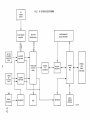
Figure 1 ^MT system block diagram ^
Figure 2
MT system rack positions ^
46
48
SUMMARY
This record describes the Bureau of Mineral Resources (BMR)
magnetotelluric (MT) data acquisition system (DAS) as used in field operations
during 1984.
This document will assist in the rebuilding of this system should a requirement
arise for further BMR MT surveys. It was considered important to document the
system and software that was operating in 1984 following the outcome of a
review into the BMR MT program. The review examined staff movements, which had
resulted in a loss of expertise in this field, and the suitability of this
method to the BMR's present scientific programs. Subsequently the BMR MT
program was suspended.
(-(
1
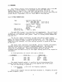
I. INTRODUCTION
The data acquisition and processing system used by BMR for MT
investigations has evolved over a number of years. This document has been
written to assist in the rebuilding of the system should it be required for use
at some future time. Included in this document are brief descriptions of the
system components and details of the data acquisition software. All software
was written using the Hewlett-Packard RTE-A.1 operating system and supercedes
that previously given by Cull & others (1981) and Spence & Kerr (1982). A
bibliography of BMR MT related publications is also included.
The MT system may be conviently divided into four parts; data acquisition,
data processing, data manipulation and data interpretation. This paper deals
with the equipment and software for the first two of these.
2. THE MAGNETOTELLURIC METHOD
The MT method is a geophysical tool for mapping subsurface electrical
conductivity. Observations are made of the natural transient magnetic field
together with the induced electric field. A detailed description of the method
is given by Vozoff (1972).
The MT technique depends on electromagnetic energy reaching the earth's
surface from two major sources. Signals with a frequency of less than about
1 Hz are usually due to ionspheric currents at heights of 75 km or greater.
Frequencies about 1 Hz and greater are usually produced by electrical or
thunderstorm activity in the atmosphere. It is assumed in the MT method that
these sources are remote; calculations are based on the assumption of plane
waves but adequate results can be obtained using curved waves with a radius of
curvature greater than several times the "skin depth" of penetration of the
earth at that frequency. These conditions occur most of the time in
sedimentary basins in Australia, but it has been found on some occasions that
plane wave conditions do not occur, and this complicates the processing of the
data.
When plane electromagnetic waves strike the earth's surface they may do so
at an angle; they are then partially reflected (at an angle equal to the angle
of incidence) and partially refracted at the air/ground interface. The angle
of refraction depends on the angle of incidence of the wave and the relative
velocity of the wave in the air and earth; typically this velocity ratio will
be many orders of magnitude, so the refracted wave will always be propagated
nearly vertically downwards into the earth. At the point of reflection on the
earth's surface, the reflected magnetic component of the wave is in-phase with
the incident component, while the electric field undergoes cancellation due to
phase reversal. The magnetic field at the air/earth interface is therefore
nearly twice its value in free-space, but the electric field component is
reduced by many orders of magnitude over its free-space value, and may be
ignored.
2
The MT technique relies on this vertically-propagated alternating magnetic
field, and the measurement of currents induced in a conducting medium (the
earth) by that field. Penetration of the wave is determined by its frequency
of oscillation and the conductivity of the medium, which together cause energy
loss due to eddy currents. The ratio of induced electric to magnetic field at
various frequencies is used to calculate apparent resistivity (i.e. the
resistivity of a uniform earth which gives the measured E/H ratio) as a
function of frequency. Apparent resistivity curves are then used to produce
one-dimensional (ID) layered models and finally in some cases, two dimensional
(2D) resistivity models.
In the MT technique the horizontal magnetic field (H field) is usually
measured with the corresponding induced electric field (E field) in two
orthogonal directions on the Earth's surface. In practice the H field is
measured by the use of three orthogonal induction coil magnetometers (Hx,Hy,Hz)
and two electrode pairs (Ex,Ey). Each pair is 600m in length centred on the
magnetometer array location.
The signals are amplified, filtered and recorded using a computer based data
acquisition system (DAS) which also provides a facility for preliminary
in-field data processing. All data is then stored on magnetic tape for further
processing prior to final interpretation.
3
3. MAGNETOTELLURIC DATA ACQUISITION SYSTEM HARDWARE
3.1 OVERVIEW
The methods used for recording MT data depend to a large extent on the
spectra of the signals being measured. Magnetic field strengths decrease
rapidly at high frequencies, to the order of 1 picotesla (1 pT), however with
the use of induction coil magnetometers a dynamic range of 100 dB is
accommodated, providing increased sensitivity at higher frequencies. These low
signal levels determine the critical design parameters for the analogue portion
of the equipment. The magnetometer coils are buried underground to reduce
noise interference and to provide thermal stability. This requires two
trenches 50 cm deep for the x and y components and a vertical auger hole 2 m
deep for the z component. The H preamplifiers are required to have extremely
low noise levels (typically 0.03 uV) and include guarded differential inputs
for chopper stabilisation to eliminate DC drift.
The E field is measured with electrodes 600 m apart. These consist of
cadmium rods inserted in porous pots containing supersaturated cadmium-chloride
solution. These are placed in contact with moist earth in a covered hole to
prevent enviromental disturbance and maintain a satisfactory ground to porous
pot contact. Multistrand copper wire is used to connect the electrodes to the
E preamplifiers. Shielding is not necessary because of the low source
impedances involved. The wire to the electrodes must be laid in a manner such
that induced EMF's are not caused by wind moving the wires. A complete
description of field procedures is given by Word & Hopkins (1971),and Vozoff
(1972).
The digital portion of the equipment is a computer-based DAS with an
interactive terminal. The data are recorded in files on a disc memory and
transferred to magnetic tape at the completion of recording at each site.
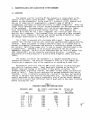
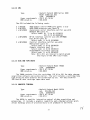
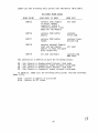
Recording at an MT site with the BMR system consists of collecting data
over specific frequency bands. These bands were selected on the basis of
dynamic range and economy in the number of data points collected. The
frequency bands, digitising interval, and number of data points collected are
given in Table 1. These factors determine the maximum bandwidth that may be
recorded. A site is normally occupied for a period of two days, during which
time up to 160 data files would be recorded onto disc. The recorded data are
usually processed to the stage of producing a plot of period versus apparent
resistivity to ensure that sufficient data of good quality have been collected
before vacating the site.
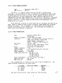
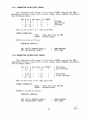
TABLE 1
FREQUENCY BANDS AND SAMPLING RATES
FREQUENCY BAND
NO.^POINTS^DIGITISING INT.
PER FILE
(Hz)
0.001
0.01
0.03
0.1
0.5
2.5
10.0
-^0.012
- 0.033
-^0.12
-^0.55
-^2.5
-^12.5
-^40.0
2048
1024
1024
1024
1024
1024
1024
4
(msec)
TYPICAL NO.
OF FILES
COLLECTED
4096
2048
1024
256
64
8
4
10
10
10
25
35
35
35
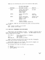
3.2 HARDWARE
This section contains brief information on each component used in the BMR
MT system. A block diagram of the equipment used in the 1984 survey
(Barton,1986) is shown in Fig. 1 and their rack positions in Fig. 2. The
following information is included in this document as an aid for rebuilding the
system should a requirement arise for future BMR MT investigations.
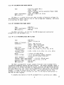
3.2.1 H-FIELD SENSOR COILS
Type^: Geotronics Model MTC-4SS
S/No.s 1005,1006,1007^(coil set 1)
1014,1015,1016^(coil set 2)
Dimensions^: overall length 2045 mm
case O.D. 76 mm
cap flange O.D. 114 mm
weight 38.6 kg
BMR vocab no.^: MMM-025
Operating temp. : -40°C to +100°C
The model MTC-4 sensor is an induction coil magnetometer. The coil itself
is wound on a laminated moly-permalloy core, then potted in polyurethane rubber
and encased in a stainless steel jacket. There is a Farady shield between the
case and coil.
The two coil signal terminations are made with special copper binding
posts; the shield terminal is a standard binding post. All three terminals are
mounted on a phenolic header located in the end of the coil. The cable is
connected to the terminals via a self-sealing cap which is bolted to the head
of the coil.
The sensor cable, Geotronics type H36-003, consists of three individually
shielded twisted pairs of untinned, stranded copper wire. The cable and
individual pair jackets are made of polyurethane rubber and the conductor
insulation is polyethylene. Connections between the coils and the
H-preamplifiers are made directly to the copper binding posts of the respective
instruments.
In field operations the sensors were used as follows
H COMPONENT^SERIAL No.s^CONNECTIONS
(+)^(-)
Hx^1005, 1014^Yellow^Green
Hy^1006, 1015^Brown^Black
Hz^1007, 1016^Red^Orange
The output terminal marked + is positive for an increasing positive
H-field directed from the terminal end to the opposite end of the sensor.
The coil sensitivity is given by
k = 137 microvolt^+ 3% on the low frequency asymptote.
gamma-Hz
Plots of the transfer function amplitude and phase vs. frequency are given
by Word & Hopkins (1971).
5
3.2.2
H-FIELD PREAMPLIFIER
Type^: Geotronics Model MTH-4
S/No.4H-003
Number of channels : 3
Connectors^: Front panel
Input : 2 copper binding posts
Input guard shield : yellow post
Signal common : black post
Calibration : red(+) & green(-) posts
Rear panel
Output : 2 paralell BNC connectors
Gain steps^: 1800, 18000, 180000
Filter^: 4-pole, 4-zero, band reject filter
with notch centred on 50 Hz.
Noise^: 0.20 uV pp rti 0.002-25 Hz
: 0.10 uV pp rti 0.002-2 Hz
: 0.05 uV pp rti 0.002-0.125 Hz
(rti^referred to input)
Chopper frequency : 2 KHz
Input voltage^: + 5mV (undistorted) +5 V (abs.max)
Output voltage^: +5 V (max)
Input impedance^: 1.45 kohm // 10 mf
Common mode rejection : 150 dB at 1 Hz
143 dB at 10 Hz
124 dB at 100 Hz
Power requirements : 115 V AC, 50 Hz, 30 W (max.)
Operating temp.^: 0°C to 50°C
BMR vocab no.^: MMA-025
The H preamplifier is a low noise, guarded differential input, choppercarrier amplifier. Three gain settings are available for each of the three
channels. Each channel also has two signal monitors. One is a zero centre
volt-meter thath reads the preamplifier output. The other is simply a red
light that will latch on if either the chopper-carrier amplifier or the output
DC amplifier approach saturation. It is reset by an adjacent push button. Two
paralell-connected outputs are provided for each amplifier, one for connection
to the postamplifier and one for signal monitoring.
Input connections are as per the sensor coils.
The transfer functions for coil and preamplifier combinations are given by
Word & Hopkins (1971).
6
3.2.3 E-FIELD SENSOR ELECTRODE
Type^: Geotronics Model MTE-2
BMR vocab no. : MME-015
The MTE-2 is a cadmium-cadmium chloride (Cd-CdC1 2 ) buffered type
electrode. The electrode wire lead is connected to a cadmium rod This should
be bound with Scotch 23 tape or similar to seal against moisture, which can
cause electrolysis to occur between the copper lead wire and the Cd rod,
subsequently causing signal degradation. The Cd rod is immersed in a saturated
solution of CdC1 2 -H20, which makes ultimate contact with the ground through a
porous ceramic pot. Caution should be exercised in the handling of this
solution as it is toxic.
Each electrode is placed in a hole about 40 cm in diameter and about 50 cm
deep. Water is added to form a slurry to ensure a good porous pot to ground
electrical contact. This arrangement is covered with a plastic bucket to
prevent rapid drying of the contact area. The electrodes are checked on a
daily basis and re-watered if required.
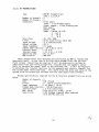
3.2.4
E-FIELD PREAMPLIFIER
Type^: Geotronics Model MTE-4
S/No.4E-003
Number of channels : 3 (two used, one spare)
Connectors^: Input : 2 binding posts, blue(+), white(-)
Input guard shield : yellow post
Signal common : black post
Output : 2 paralell BNC connectors
Gain steps^: 10, 100, 1000
Filter^: 4-pole, 4-zero, band reject filter
with notch centred on 50 Hz.
Noise^: 3.0 uV pp rti 0.002-25 Hz
Chopper frequency : 2 KHz
Input voltage^: + 1 V (undistorted),+8 V (abs.max)
Output voltage^: T5 V (max)
Input impedance^: > 100 kohm
Common mode rejection : 100 dB at 1 Hz
86 dB at 20 Hz
74 dB at 200 Hz
60 dB at 2 kHz
Power requirements : 115 V AC, 50 Hz, 25 W (max.)
Operating temp.^: 0°C to 50°C
BMR vocab no.^MMA-020
The E preamplifier is essentially the same as the H preamplifier. The
input electrode connections are shown below.
ELECTRODE^AMPLIFIER CHANNEL^TERMINAL
Ex+ (north)^1^RED
Ex- (south)^1^GREEN
Ey+ (east)^2^YELLOW
Ey- (west)^2^BLACK
The guard shield and the signal ground are left floating.
7
3.2.5 MT CALIBRATOR AND POWER MONITOR
Type^: Geotronics Model MTC-2
S/No. 2C-001
: Hewlett Packard function generator Model 3300A
S/No. 939-05086
Power requirements : 115 V AC, & 240 V AC, 50 Hz
BMR vocab no.^: MMC-080
The MTC-2 is a system service unit that provides calibration voltages for
the preamplifier inputs, monitors the AC line voltage and frequency, and serves
as an auxilary DC power supply.
3.2.6 MT POSTAMPLIFIER POWER SUPPLY
Type^: BMR MTA-1
Power requirements : 240 V AC, 50 Hz
BMR vocab no.^: MMP-055
The MTA-1 provides + 15 V DC for the BMR designed and constructed
preamplifiers and postamplifiers.
3.2.7 MT E & H POSTAMPLIFIERS AND FILTERS
Type^: BMR MTA-1
S/No.s 1,2,3,4,5,6
Number of channels : 5
Connectors^: Input : BNC floating
Output : BNC single ended
Power : Cannon 14-P-5P
Gain steps^: 3, 10, 30, 100, 300, 1000, 3000
High pass filter^: 0.001, 0.01, 0.03, 0.1, 0.5, 2.5, 10 Hz
(3 dB points)
Low pass filter^: 0.012, 0.033, 0.12, 0.55, 2.5, 12.5, 40 Hz
(3 dB points)
Noise^: 1 uV pp rti 0.001-40 Hz
Output voltage^: +1.2 V (on recorder output terminal)
+ 12 V (on CPU output terminal)
Input impedance^: 10 kohm
External Power requirements : + 15 V DC, 400 mA (max)
Internal Power requirements : + 12 V DC, + 5 V DC
Operating temp.^: 0°C to 50°C
BMR vocab no.^: MMA-030
The MTA-1 postamplifier accepts outputs from the E and H preamplifiers.
It performs bandwidth shaping and amplification. The output analogue signal is
interfaced to the Phoenix analogue-to-digital converter and monitoring devices.
Gain settings on all five channels are independent of each other, but they may
be controlled by the CPU. High- and low-pass filter settings are slaved from
channel 1, or may be controlled by the CPU. Logic controls for all five
channels of filter and gain settings are sent via the digital multiplexer to
the CPU for data logging.
A complete description of the MT postamplifiers is given by Lui (1983).
8
3.2.8 SIXTEEN-CHANNEL DIGITAL MULTIPLEXER
Type^: BMR XDM-1
S/No. 2
Power requirements : 115 V AC, 50-400 Hz
BMR vocab no.^: XDC-CV7
The XDM-1 allows a number of devices to be connected to the CPU for
input/output operations. For the MT system five channels were used as given
below.
CHANNEL^INPUT
0^Ex & Ey Preamp gain and filter settings.
1^Hz, Hx & Hy Preamp gain and filter settings.
2 to 4^Postamplifier E & H gain and filter settings.
When this device is used with the Geotronics preamplifiers the inputs
require voltage level translation to TTL compatability. To allow for this the
inputs on channels 0 and 1 are optically isolated. Details on this are given
by Devenish (1979). Optical isolation is not required if the BMR-constructed
preamplifiers are used.
3.2.9 PROGRAMMABLE OSCILLATOR
Type^: BMR SPO-1
Power requirements : 240 V AC, 50 Hz
BMR vocab no.^: SPR-130
The SPO-1 is a programmable oscillator that provides a number of output
frequencies that are used to control the sampling rates (Table 1) for the
analogue-to-digital conversion carried out by the Phoenix equipment. This
device is controlled by the six least significant bits (LSB) of a 16 bit duplex
register (i.e. bits 0-5). Bits 0-4 determine the output frequency whilst
switching of the oscillator is by bit 5. With bit 5 at logic 1 (0 V) the
output is enabled and disabled when bit 5 is logic 0 (+12 V). The cutoff
frequency for an anti-aliasing filter is selected by the three LSB of the
duplex register. Input settings of "000" or "111" disable the filter. The
oscillator is interfaced with the CPU which provides the logic control for the
output frequency selection.
3.2.10 PHOENIX DATA ACQUISITION SYSTEM
Type^: Phoenix Data Inc. Model 6915-3754 &
Model PDI Standard Subsystem Interface
Power requirements : 240 V AC, 50 Hz
BMR vocab no.^: XDI-DA3
The 6915 is an analogue-to-digital converter which is used in conjunction
with the PDI Standard subsystem interface for the acquisition of MT data. The
sampling rates are controlled by the CPU via the programmable oscillator and
the digitised data is sent to the CPU for storage onto disc. Full details on
this equipment is given by Phoenix Data Inc. (1976,1977).
9
3.2.11 MT PREAMPLIFIERS
Type^: BMR MT Preamplifiers
S/No.s 1,2,3,4,5
Number of channels : 5
Number of channels : 5
Connectors^: Front panel
Input : 2 red binding posts
Signal common : silver binding post
Rear panel
Output : BNC
Power : Cannon 14-S-5P
A - +15 V
B - -15 V
C-^0 V
Gain steps^: 10, 100, 1000
Filter^: 50 Hz notch filter (38.6 dB)
Input Voltage^: +1 V (undistorted)
Output voltage^: +12 V
Input impedance^: 2.2 mohm
Common mode rejection : 64.4 dB at 10 Hz
External power^: + 15 V DC
Internal power^: + 12 V DC, + 5 V DC
Operating temp.^: 0°C to 50°C
BMR vocab no.^: MMA-026
-
These preamplifiers were designed and constructed by BMR to replace the
Geotronics units. At the time of writing these preamplifiers had not been
field tested. Should they be required it will be necessary to include an
additional fixed gain field preamplifier situated with the magnetic sensor
coils to increase the signal level to the recording cab. It will be necessary
to determine the transfer functions for the magnetic and electric channels for
the system under field conditions. This would allow the poles and zeros of the
system to be calculated and included into the data acquisition software.
Design specifications required for the H-field pre-preamplifiers are given
below.
Number of channels : 3
Gain^: 100 (fixed)
Filter^: 0 - 100 Hz (fixed bandwidth)
Input impedance^: 1.45 kohm // 10 uf
Common mode rejection : 120 dB (typical)
Internal power^: + 6 V DC (batteries)
Max. noise^: 0.20 uV pp rti 0.002 - 25 Hz
Sensitivity^: 0.05 V/gamma (approx) when combined
with the MTC-4SS coil
10
^
3.2.12 CPU
Type^: Hewlett Packard A600 Series 1000
Model 2156A opt.015
S/No. 2309A00319
Power requirements : 240 V AC, 50 Hz
BMR vocab no.^: XDC-DC30
The CPU included the following cards:
2 x HP5180^A600 memory control PROM card (ports 1 & 2)
1 x HP12101^A600 PROM processor card (port 3)
1 x HP12005A^Asyncronous serial interface card for use with
HP2623A VDU (port 4)
Select codes: Ul (1 to 8) CCCOCCCC
U21 (1 TO 8) 0000CCOC
1 x HP12009A^HP TB interface card for use with HP7908A
Disc Drive (port 5)
Select code: (1 to 8) OCC00000
3 x HP12006A ^Parallel interface card for use with:
Multiplexer (port 6)
Select code: (1 to 8) 0000CCOO
Phoenix interface (port 7)
Select code: (1 to 8) 0000CCCO
Programmable oscillator (port 8)
Select code: (1 to 8) 0000CCOC
Note: R6 to R11 are removed to match ground
true logic of the SPO-1 oscillator.
3.2.13 DISC AND TAPE DRIVE
Type^: Hewlett Packard Model 7908A
S/No. 2208A00890
Power requirements : 240 V AC, 50 Hz
BMR vocab no.^: XDC-DD12
The 7908A contains five disc cartridges (CR 16 to 20) for data storage,
acquisition software and system control. The unit includes a cartridge type
tape drive for data archival and system back-up use. For data archival
150 foot HP data cartridge tapes were used.
3.2.14 COMPUTER TERMINAL
Type^: Hewlett Packard Model 2623A
opt. 015,050,262
S/No. 2226V19232
Power requirements : 240 V AC, 50 Hz
BMR vocab no.^: BC-DT11
The 2623A is used for interactive control of data acquisition and
processing. It includes a graphics capability and a thermal printer which
allows hardcopy plots of processed data to be produced in the field.
11
3.3 SYSTEM RECONFIGURATION
The BMR MT data acquisition system was decommissioned during 1985. With
the exception of the HP A600 computer system and the Phoenix equipment all
components were placed in storage. Should this system be required the
following points may be of assistance.
(i)
All software is written under the RTE-A.1 operating system and is
archived on HP1000 9 track tape and HP data cartridge format.
(ii) It will be necessary to design and construct pre-preamplifiers for the
three magnetic channels. These would be located at the sensing coils and
provide sufficient gain for the inputs of the BMR preamplifiers.
(iii) The BMR constructed preamplifiers were not field tested prior to the
system being dismantled.
(iv) The transfer function for the complete system would have to be
determined as the present poles and zeros information is not valid for the
revised equipment. Software for data acquisition and interfacing cables are
available for this replacement equipment.
12
4. MAGNETOTELLURIC DATA ACQUISITION SYSTEM SOFTWARE
4.1 INTRODUCTION
4.1.1 OVERVIEW
This chapter describes the magnetotelluric data acquisition system
software (MT DAS) which used the HP RTE-A.1 operating system in an HP A600
computer with a 2623A graphics terminal and 7908A disc and cartridge tape unit.
The software was written during the first quarter of 1984 at the BMR, and
updated in early 1985 with the replacement of the Geotronics preamplifiers.
This software supercedes that which ran on the old HP [-series computer It
has an enhanced user interface (program MAGTL) in addition to having a
simplified program structure (modular programs written in FORTRAN 77), and a
rationalised data file structure (i.e. no duplication of data items within data
files along with the use of files with variable length records).
In addition to the MT DAS programs, there are several utilities which
facilitate file manipulation, archiving and purging, as well as a help file, an
answer file, a status file, and of course the data files.
All system software is archived on HP data cartridge and 9-track magnetic
tape formats. Data processing software is given by Moore (1976,1977), and
Spence & Kerr (1982).
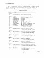
4.1.2 DATA FILES
There are three types of data files:
MTnnnn files - Data files made by MAGTL on disc cartridge 19.
FTnnnn files - Fourier transform files made from MTnnnn files by
program FFT. They are usually on disc cartridge 20,
but can be on 16 and 17 as well. They have a
security code of 50.
Tense files - These are the tensor rotation files ROTTEN and TIPPER.
They are made by program TENSE from FTnnnn files.
They normally reside on cartridge 18 and have a
security code of 50.
The different input/output (I/O) system of the A-series CPU necessitated
writing new interface drivers for the Phoenix analogue-to-digital converter,
the SPO-1 programmable oscillator and the XDM-1 multiplexer.
All of the above components of the MT DAS are described in the following
sections.
13
4.2 USERS GUIDE
4.2.1 SYSTEM INITIALISATION
After powering up all hardware components, the MT DAS system is booted up
by typing:
%BDC0027BCF01 (or %BDC0027 for the development system)
and pressing carriage return. After the system has been booted up, the time
must be set with the FMGR TM command,
e.g.
TM,hrs,min,sec,month,date,year
At the start of each new site, the following action must be taken:
1. Transfer control to procedure file PUDATA to archive and purge
all data files from the previous site.
2. Run MAGTL and type IN to initialise the answer file.
3. Type UP to update the answer file.
The MT DAS system is then ready to use. User interface to the system is
obtained by running program MAGTL, the main control routine, in FMGR.
e.g.
RU,MAGTL
MAGTL will clear the screen, write out a heading that includes the current
version number and issue a prompt for a command input
eg.
MAGTL - MT Data Acquisition System <861204.1423>
Type HE for help, EX to exit
MAGTL:
The valid inputs to MAGTL are:
AB
AQ
BR
CU
EN
EX
FT
HE
IN
RE
RX
ST
UP
-
-
to
to
to
to
to
to
to
to
to
to
to
abort data acquisition immediately and purge data file.
start data acquisition.
break (abort) data acquisition at next file.
display the current answer file.
end MAGTL and disable printer if it was enabled.
exit from MAGTL, leaving printer status unaltered.
display the number of files collected in each frequency band.
display the MT help file.
initialise the MT answer file.
enable the printer for hard copy reports.
disable the printer.
to display the MT survey status file.
to update the MT answer file.
14
If MAGTL cannot recognize a command input, e.g. CC, it will respond in the
following manner:
MAGTL: CC is an Illegal Input.
Type HE for help, EX to exit
The two character command inputs are not followed by a carriage return as
there is an automatic data transmission whenever a two character command is
typed.
4.2.2 ANSWER FILE INITIALISATION
The IN command should be used with caution as it will preset the answer
file to an initial state. It is useful when the answer file is nonexistent.
4.2.3 ANSWER FILE UPDATE
After the UP command the user is prompted to update the answer file. This
command operates by displaying in turn the current values for various data
items, e.g. coil set used, electode resistance and frequency band to sample.
For each displayed value a new value can be input or the return key pressed for
no change.
To reset a value to zero, -1 must be typed as in this system a zero is
equivalent to pressing the return key.
The answer file is contains a character string of 54 letters and several
numeric items. The character string is used to contain details on the site.
It can be updated with the aid of a restricted editor function that interprets
a "/" by leaving that character position unalterd in the old string, and a "\"
by deleting the character in that position from the old string.
e.g.
ANSWER FILE UPDATE
Survey Site is: FINAL TESTING OF MAGTL AT BMR 27-3-84
New Site or Cr: //////////\\\/////////////////28/////.
New Site is: FINAL TEST OF MAGTL AT BMR 28-3-84.
The character string is updated first, followed by the following numeric
items:
Azimuth (deg); Coil Set used; Ex Separation(m); Ey Separation(m);
Rx Resistance(ohms); Ry Resistance(ohms);
Effective Ex Separation (automatically calculated);
Effective Ey Separation (automatically calculated);
Next File No.; Freq.Band No.; No of Samples;
Dig.Int.(msecs); Files in band;
Post Amp.Gains;
E Preamp.Filters; E Preamp.Gains;
H Preamp.Filters; H Preamp.Gains;
Low & High Pass Filter Bands.
15
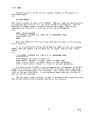
4.2.4 DATA ACQUISITION
Additional input is required after the AQ and UP commands. After the AQ
command, MAGTL will ask for the number of data files to be collected. In the
example below, two files are collected according to the information contained
in the answer file.
MAGTL: Acquire how many files Doc? 2
Data Acquisiton Started for 2 Files.
MAGTL:
4.2.5 ACQUISITION MONITORING
Once data acquisition has started, control returns to MAGTL and other
commands can be entered. The answer file cannot be updated during an
acquisition because the acquisition uses data from it. Hence if the CU or UP
commands are entered their only action is to respond with:
DATA ACQUISITION IN PROGRESS NO ACCESS TO MTANS
Note also that the AQ command must not be entered again until after the
current acquisition has finished. If AQ is accidently input to MAGTL, the user
must ask for zero files and control will return to MAGTL without requesting an
acquisition to start.
After each file has been acquired, a message is written on the status file
(MTSTAT) saying what file was acquired and when it was completed. A message is
output to the VDU saying how many files were recorded when an acquisition is
finished.
e.g.
ACQUISITION COMPLETE FOR 2 FILES
It can be determined whether data acquisition is currently in progress by
one of several means:
1. Observe the Phoenix A-to-D converter - the lights flash during
data acquisition.
2. Enter CU or UP - these commands will indicate if acquisition is
in progress.
3. In FMGR, enter PL and observe if program AQUIR is doing I/O to
LU 30 (the Phoenix)
4. Type ST in MAGTL and check whether the last data file has
been completed.
16
4.2.6 TROUBLE SHOOTING
If the MT DAS system cannot access any of the files it uses, it will
report the appropriate FMGR error code. If any errors are reported, they
should be investigated before re-running MAGTL. The following files are used
by MAGTL and must exist:
MTANS::18^- the answer file
MTSTAT::18^- the status file
MTHELP:LA:18 - the help file
In addition to the above, MAGTL uses a temporary scratch file on disc
cartridge 19 called 'NEWDAT'. This file should only exist during actual data
acquisition and should only be opened to program AQUIR. After ACQUISITION
COMPLETE FOR n FILES it will be purged.
If the A-to-D converter fails to stop on completion of the file
acquisitions, down (DN,-31) then up (UP,-31) the programmable oscillator
(SPO-1).
It is the users responsibility to manage the number of files on cartridge
19 and ensure that there is sufficient room for subsequent data acquisition.
Several utilities exist to assist the user to do this. They are outlined in
the next section.
The ST command in MAGTL can be used to determine how full data cartridge
19 is. It is displayed as a blinking percentage in the top right hand corner
of the screen.
The first file acquired should always be checked to determine whether all
wires have been connected properly.
4.2.7 DATA ARCHIVAL AND RETRIEVAL
For archival onto magnetic tape (LU 24) the following commands are used:
,PUDATA - Archives FTnnnn, MTnnnn, ROT---, and MTSTAT files onto
tape using PURGE subroutine. These files reside on
cartridge 17.
,UPDATA - Recovers files from tape using RTREVE subroutine.
,STDATA - Recovers all data files from tape using RECOVR subroutine.
These procedure files reside on cartridge 16 but if these are to be used
for data files residing on cartridge 16 then STDATA and RECOVR should be moved
to cartridge 20 and purged from 16 so as to avoid a cartridge lock-out error.
17
This may be done as follows:
Copy files to another cartridge:
CO,namr::source-cr,dest-cr
Purge the file from the source cartridge:
PU,namr:sec-code:cr
Or if desired instead of purging the file may be renamed by:
RN,old-namr:sec-code:cr,new-namr
Other useful commands for tape handling are the File Copy (FC) commands:
LH,-24 - list tape header
LC,-24 - list comment file
DL,-24 - list all files on tape
Selected files on tape may also be transferred to a cartridge using the FC
command:
CO 3 -24,namr::cr
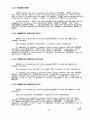
4.2.8 FMGR 005 ERRORS
-
These occur when a file has been corrupted, e.g. due to filling up a
cartridge (usually file ROTTEN:50:18)
This is remedied by purging the corrupt file and any other unwanted files
on the cartridge (do a DL,cr,HP), packing the cartridge, and trying again.
If there is still not enough room, then move files from this cartridge
onto another using the procedure file MOVE. This will prompt for the "from"
cartridge, security code, the "to" cartridge and the files to move. The user
must precede the above answers with a ":", and terminate this procedure file
with a ":,/E".
4.2.9 FMGR 019 ERRORS
-
These occur when running a program or a procedure file.
They are caused because the program involved has not been linked for the
current operating system.
It is corrected by re-linking the program under the current operating
system. (see the LINK manual)
18
4.2.10 FMGR-033 ERRORS
No room on cartridge 19.
This is remedied by examining the contents of cartridge 19 using DL,19.
If there are only MTnnnn files on CR 19 then either sufficient data for the
current site has been acquired, or the previous sites MTnnnn files have not
been archived onto tape.
If there are any other files files on CR 19 (e.g.NEWDAT) they should be
moved onto either CR 16 or 17, or purged if not wanted.
CR 19 should then be packed prior to restarting any further data
acquisition.
19^
C't
4.3 MT UTILITIES
4.3.1 OVERVIEW
There are several utilities used in conjunction with the MT DAS There are
procedure files, invoked from FMGR by typing a comma followed by the procedure
file name, and programs, invoked with the RU command.
The procedure files are:
ARCH^- to archive
PUDATA - to archive
STDATA - to restore
PLINK - to relink a
the system using the HP program called FC
and purge data files from the MT DAS onto tape
data files from tape onto disc
specified program for the MT DAS
While the programs are:
PUFT^- purges FTnnnn files from the system.
PUMT^- purges MTnnnn files from the system.
CHEK^- checks the data from a specified channel on a specified
MTnnnn file.
FFT^- processes MTnnnn files into FTnnnn files.
TENSE - processes FTnnnn files into ROTTEN and/or TIPPER files.
MTPLT - produces plots of apparent resistivity vs. period, phase
angle vs. period, and rotation angle vs. period.
SCREE - screens out scattered rotated tensor analysis and phase
data.
SCRAV - averages screened data and formats it for 1D inversion.
The processing programs SCREE and SCRAV are described by Moore (1977) and
wil not be dealt with in this document.
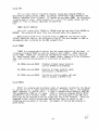
4.3.2 PUMT AND PUFT
PUMT and PUFT should be used with caution. Data files are not generally
purged, but archived onto tape using the PUDATA procedure file. When PUMT or
PUFT is run, a start file number and stop file number must be provided as run
parameters. These programs will run faster if a cartridge number is specified
as a third parameter.
e.g.
RU,PUFT,3,45,20
This will purge files in the range FT0003 to FT0045 from cartridge 20.
PUNT and PUFT will display on the VDU the file names as they are purged.
20
4.3.3 CHEK
Checks the data in an MT file by a graphic display of the signal in a
specified channel.
i.e.
RU,CHEK,MT0055
will check a channel of data on file MT0055. CHEK will open the specified file
or terminate with an error if it can not be found on cartridge 19. The file
name and its header record are then written on the screen. CHEK can be
terminated, by typing EX, or continued by hitting the RETURN key.
e.g.
FMGR : RU,CHEK,MT0500
File MT0500 is BROKEN HILL 1984 SITE 14 YANCOWINNA CREEK
************* Ex
FMGR:
Note that CHEK will clear the screen when run, and that it will not echo
the EX typed in.
If it is continued by hitting the RETURN key, CHEK will ask for a channel
number (only one channel can be looked at), an offset, and an X and Y scale
factor.
e.g.
File MT0500 is BROKEN HILL 1984 SITE 14 YANCOWINNA CREEK
*************
Enter Channel:<3> (look at channel 3)
Enter Offset. Default is 1:<100> (start at sample 100)
Enter Y Scale. Default is 20000:<return> (Y scale defaulted)
Enter X Scale factor. Default is I:<return> (X scale defaulted)
A Y scale factor of 20000 is usually adequate for all channels of MT data.
A smaller Y scale will cause the displayed data to be magnified in amplitude,
useful if the recorded signals are very weak. The X factor will stretch the X
scale by the specified factor. A starting point other than the first bit of
data may also be specified.
The file name, header, and plot of data is written on the screen which can
then be hard-copied using the graph copy key on the terminal.
21
4.3.4 FFT
FFT is a fast fourier transform program, based upon program FFOUR as
described by Spence & Kerr (1982), to process raw MT data files (MTnnnn) into
fourier transform files (FTnnnn). FFT should be run under CMND. No indication
is given when it stops. When running FFT, a start file number (nnnn) and the
number of files to process (mm) must be specified.
e.g.
CMND: RU,FFT,0250,50
This will create files FT0250 to FT0299 from the raw data files MT0250 to
MT0299. The original MT data files are retained after this operation.
When processing MT files acquired prior to 1985 the old version of FFT
(FFT01) should be used as the structure of the MT file was changed in 1985 to
accommodate data collected by the BMR preamplifiers.
4.3.5 TENSE
TENSE is a program which carries out the tensor analysis of the data. It
is based on program TENSR as given by Spence & Kerr (1982). TENSE should be
run in FMGR. TENSE will indicate on the VDU each FTnnnn file as it accesses
it. When running TENSE, a start file number (nnnn), number of files to process
(mm), and a processing parameter in octal must be specified.
e.g.
RU,TENSE,nnnn,mm,4540B
Produces rotated tensor analysis
with no ROTTEN file produced.
RU,TENSE,nnnn,mm,4050B
Requires an input rotation angle
and produces a ROTTEN file.
RU,TENSE,nnnn,mm,4040B
Calculates rotation angles and uses
them to produce a ROTTEN file.
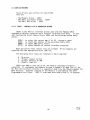
4.3.6 MTPLT
MTPLT is a program which produces plots of apparent resistivity (in ohm-m)
vs. period (in sec.), phase angle (in degrees) vs. period (sec.), and rotation
angle (degrees) vs. period (sec.). It uses a rotated tensor analysis (ROTTEN)
file produced by TENSE as its input. TENSE is based on programs MTPLR, MTPLP
and MTPLA as given by Moore (1976). The plots are displayed on the VDU and a
hard-copy may be obtained using the graph copy key on the terminal. These are
examined in the field to assess data quality and later to assist in the
screening and averaging of the data. An example of running the program is
given below.
22
FMGR: RU,MTPLT
OPTIONS: 1 RHO, 2 PHASE, 3 ROTATIONS (-'ye for points)
1
OPTIONS: 1 ROUTINE, 2 VARIATIONS
2
NPD, TCENTRE, COHLIM(2), SKEWLIM(2)
10,1,0.7,0.8,1.0,0.5
ERROR BARS: 0 NONE, 1 ST. DEVIATION, 2 ST. ERROR
1
"NAME OF INPUT FILE":
ROTTEN
The above example would produce XY and YX plots of resistivity vs. period
with standard deviation error bars. The VARIATIONS option allows the user to
input the following, option ROUTINE uses the default values.
NPD^Number of data points per decade (default 10).
TCENTRE^Cutoff (or centre) period (default 10).
COHLIM(2) Lower and upper coherency limits (default 0.8,0.8).
SKEWLIM(2) Upper and lower skew limits (default 1,1).
23
4.4 DEVICE DRIVERS
Three drivers were written for the MT DAS
They are:
- The Phoenix driver - 1D$57
- The SPO-1 oscillator driver - 1D$70
- The XDM-1 MUX driver - 1D$62
4.4.1 1D$57 - PHOENIX A-TO-D CONVERTER DRIVER
1D$57 is the RTE-A.1 interface driver used with the Phoenix 6915
analogue-to-digital converter and a Parallel Interface Card (PIC). It uses
self-configuring Direct Memory Access (DMA) and the folowing system entry
points:
$SELR
$DIOC
$DMPR
$1FTX
-
to
to
to
to
select
return
report
return
the correct map (1 of 32 - system or user)
the address of the Interface Table (IFT)
DMA parity errors
address of current interface extension
Read and Control EXEC request only are allowed. Write requests are
rejected with the appropriate error code set.
The following error codes are returned in the A register:
0
1
2
3
-
No error
Illegal request (write)
Illegal interupt on DMA
Phoenix timed out
1D$57 uses DMA to read off LU 30, the Phoenix analogue-to-digital
converter. It configures the Phoenix to read 5 channels of data (Ex, Ey, Hz,
Hx, Hy) with external clocking in a sequential mode (see the Phoenix manual for
more details). External clocking of the Phoenix is provided by the SPO-1
Programmable oscillator. 1D$57 is used when data acquisition is in progress.
24
1D$57 uses the following entry points into the Device Table (DVT).
DVT ENTRY POINT USAGE
ENTRY POINT
UPON ENTRY TO 1D$57 ^UPON EXIT
^
contains EXEC request
not used
to select random/
sequential output &
internal/external clock
modes for the Phoenix
$DVT15
$DVT16^contains EXEC buffer^contains
address^ error code
$DVT17^contains EXEC buffer^contains translength^
mission log
$DVT18^contains optional Phoenix
start and end channel ^not used
address in lower and upper
bytes respectivly
^
$DVT19
not used (optional)^contains neg.
DMA count
The subfunction in $DVT15 can have the following values:
OB
1B
2B
3B
-
Puts
Puts
Puts
Puts
Phoenix
Phoenix
Phoenix
Phoenix
in
in
in
in
Random output External clock mode
Sequential output External clock mode
Random output Internal clock mode
Sequential output Internal clock mode
In addition, 1D$57 uses the following entry points into the Interface
Table (IFT):
$1F5 - pointer to address of active DVT
$1F6 - pointer to IFT status
25
4.4.2 1D$62 XDM-1 MUX INTERFACE DRIVER
1D$62 handles I/O to the multiplexer on LU 32. NOTE that for historical
reasons some wiring has been done back to front on this equipment, so the bit
order of the incoming data from the filter switches has to be reversed in this
driver
1D$62 is the RTE-A interface driver used with the BMR XDM-1 multiplexer
and a Parallel Interface Card (PIC).
It uses the folowing system entry points:
$WR1T - to write 1 word into the users data buffer
$DIOC - to return the address of the Interface Table (IFT)
Read and Control EXEC request only are allowed. Write requests are
rejected with the appropriate error code set.
The Following error codes are returned in the A register:
0
1
2
3
-
No error
Illegal request (write)
Illegal interupt
MUX timed out
1D$62 is invoked by a user EXEC call with the following format
CALL EXEC(1,ICNTWD,IBUFAD,NUMBER,IUNIT)
where:
1^- specifies a read
ICNTWD - specifies the MUX LU (32) in the lower 6 bits and the
starting channel in the next 4 bits (6 to 9)
IBUFAD - is the buffer address where the driver will put the
data read off the specified channels
NUMBER - is an option that specifies the buffer length
and hence the number of channels to read. This defaults to 1.
IUNIT - is an option that specifies the unit number of the MUX
where several MUX's are chained together. It is not
normally used and will default to O.
26
^
1D$62 uses the following entry points into the Device Table (DVT).
DVT ENTRY POINT USAGE
^
UPON ENTRY TO 1D$62^UPON EXIT
ENTRYPOINT
^
^
contains EXEC request
not used
VT 15
and subfunction to
select starting
channel number
$DVT16^contains EXEC buffer^contains
error code
address^
^
^
contains EXEC buffer ^ contains trans$DVT17
length i.e. number of
mission log
channel to read
(default is 1)
$DVT18
^
contains optional
selection parameter (default=0)
In addition, 1D$62 uses the following entry points into the Interface
Table (IFT):
$1F5 - pointer to address of active DVT
$1F6 - pointer to IFT status
4.4.3 1D$70 SPO-1 PROGRAMMABLE OSCILLATOR DRIVER
1D$70 controls the programmable oscillator. It outputs a function code to
LU 31, which determines the oscillator frequency. The FMGR command CN can be
used to control LU 31 via 1D$70.
CN,31,25B,-3^- Starts the oscillator at a frequency
corresponding to -3
CN,31^- does a reset
CN,31,25B,-20^- will stop the oscillator
1D$70 is the RTE-A interface driver used with the SPO-1 Programable
Oscillator and a Parallel Interface Card (PIC).
Control EXEC request only are allowed. Read and write requests are
rejected with the appropriate error code set.
The following error codes are returned in the A register:
0 - No error
1 - Illegal request (read or write)
3 - SPO-1 timed out
27
1D$70 uses the following entry points into the Device Table
(DVT).
DVT ENTRY POINT USAGE
UPON ENTRY TO 1D$70
UPON EXIT
SDVT15
contains EXEC request
code & function
not used
$DVT16
contains frequency
selection code
contains
error code
ENTRY POINT
The subfunction in $DVT15 can have the following values:
OB - to issue clear request to register 32 (to reset PIC)
25B - to select the frequency defined by parameter 1.
Parameter 1 can have the following octal values :11
10
7
6
5
4
3
2
1
0
-1
-2
-3
-4
-5
-6
-7
-10
-11
-12
-13
-14
-15
-16
-
To
To
To
To
To
To
To
To
To
To
To
To
To
To
To
To
To
To
To
To
To
To
To
To
select
select
select
select
select
select
select
select
select
select
select
select
select
select
select
select
select
select
select
select
select
select
select
select
an
an
an
an
an
an
an
an
an
an
an
an
an
an
an
an
an
an
an
an
an
an
an
an
output
output
output
output
output
output
output
output
output
output
output
output
output
output
output
output
output
output
output
output
output
output
output
output
frequency
frequency
frequency
frequency
frequency
frequency
frequency
frequency
frequency
frequency
frequency
frequency
frequency
frequency
frequency
frequency
frequency
frequency
frequency
frequency
frequency
frequency
frequency
frequency
of 512
of 256
of 128
of ^64
of ^32
of ^16
of ^8
of ^4
of ^2
of ^1
of 500
of 250
of 125
of ^62.5
of ^31.25
of ^15.625
of ^7.8125
of ^3.90625
of ^1.953125
of ^0.976563
of ^0.488281
of ^0.244141
of ^0.122070
of ^0.061035
kHz
kHz
kHz
kHz
kHz
kHz
kHz
kHz
kHz
kHz
Hz
Hz
Hz
Hz
Hz
Hz
Hz
Hz
Hz
Hz
Hz
Hz
Hz
Hz
i.e. the frequency (kHz) = 2 ,where n = the parameter value
e.g. in FMGR - to select an output frequency of 125 Hz, do
CN,31,258,-3
28
4.5 DATA ACQUISITION SYSTEM SOFTWARE COMPONENTS
The Data Acquisition System (DAS) is controlled by the main control
program MAGTL. MAGTL is a FORTRAN program that operates by executing the
appropriate program upon receipt of a two character command. It also
initialises the status file MTSTAT.
The initialization process is performed by MAGTL executing the program
INITL upon receipt of the IN command. This is NOT done automatically. INITL
simply sets up the MTANS file with default values.
The program UPDAT must then be run via the UP command to put meaningful
site information into the MTANS file, including the switch settings on the
amplifiers which are read from the MUX.
The actual data acquisition is performed by the program AQUIR executed via
the AQ command. AQUIR creates the specified number of MTnnnn data files,
placing the site information from the MTANS file at the head of each file
followed by records containing the gain, poles and zeros for each channel as
determined by the switch settings in the MTANS file. It also updates the
status file MTSTAT.
Various programs exist to monitor the status of the system. CURNT
displays the site information contained within the MTANS file. Any incorrect
fields can then be corrected using UPDAT. STATS displays the data acquisition
status, read from the MTSTAT file. FILES displays the number of files
collected in each frequency band.
4.5.1 PROGRAM MAGTL
MAGTL is the main control routine for the MT DJ-\S. It operates by ensuring
that the MT status file (MTSTAT::18) exists, and prompts the user for a valid
input.
Valid inputs are:AQ
AB
BR
EN
EX
-
CU
Fl
HE
IN
RE
RX
ST
UP
-
Start data AcQuisition
ABort data acquisition immediately
BReak (abort) data acquisition at next file
ENd MAGTL, disable printer if enabled
EXit from MAGTL, printer will remain enabled if
enabled
Display CUrrent answer file
Display FIles collected in each frequency band
Display the HElp file
INitialises the MT Answer File to l's and O's
Enable the printer for hard copy REports
Disable the printer
Display survey STatus
UPdate the answer file
It then performs the specified command, scheduling the appropriate program
where necessary.
29
4.5.2 PROGRAM INITL
INITL is scheduled by typing IN, it opens the MTANS file and writes out
the nine records below with default values for the fields. Some of the
defaults are meaningless and thus MTANS must be updated prior to data
acquisition using UP.
MTANS file format
Size^Name
Record 1
27^site information - ASCII character string
Record 2
1^AZIMUTH
ICOIL SET
1^Ex SEPARATION
1^Ey SEPARATION
2^Rx RESISTANCE
2^Ry RESISTANCE
2^NEXT FILE NO
1^FREQ—BAND1^FILES IN BAND
1^No POINTS
2^Dn- INTERVAL
7
-
relative to magnetic North
coil set 1 or 2
in metres
in metres
in ohms
in ohms
No. of next MTnnnn file
No. of freq. band
No. of files in each freq. band
No. of points collected
Digital interval in msec
7 frequency band counts
Record 3
5^POSTAMP GAINS(5) - array 1-5 (Ex,Ey,Hz,Hx,Hy)
= gain switch settings (1 to 7)
Record 4
3^EPRE FILTERS(3)
- array 1-3 (Ex,Ey,Ez) (Ez unused)
= filter settings (not used)
Record 5
3^EPRE GAINS(3)^- array 1-3 (Ex,Ey,Ez) (Ez unused)
= gain settings (1 to 3)
Record 6
3^HPRE FILTERS(3) - array 1-3 (Hz,Hx,Hy)
= filter settings (not used)
Record 7
3^HPRE GAINS(3)^- array 1-3 (Hz,Hx,Hy)
= gain switch settings (1 to 3)
Record 8
2^FILTER PASSES(2) - array 1-2 (LP filter, HP filter)
filter switch settings (1 to 7)
Record 9
2^PRE AMPS(2)^- array 1-2 (E preamps, H preamps)
= 1 (old preamps)
= 2 (new preamps)
30
<72
4.5.3 PROGRAM UPDAT
UPDAT allows the user to update the contents of MTANS. MTANS contains
data that will be used as input to the data acquisiton routine. Most of the
data on this file ends up on the data file header. MTANS can be veiwed quickly
using the ST command in MAGTL. UPDAT is scheduled in MAGTL by typing UP.
Fields AZIMUTH,..,NEXT_FILE_No,No_POINTS,DIG_INTERVAL and PRE AMPS are all
prompted for via one of the subroutines READI, READR or READM. The fields
FREQ_BAND, POSTAMP_GAINS,...,FILTER_PASSES are taken from the switch positions
read off the multiplexer and decoded using the assembler subroutines DECOD or
DECID.
4.5.4 SUBROUTINE READI(OLD_DATA)
READI is a subroutine called by program UPDAT to read and update an
integer variable.
One integer parameter (OLD_DATA) is passed to this subroutine.
It operates by reading a response from a users terminal into the INTEGER
variable called NEW_DATA. READI then checks if NEW_DATA is non-zero, and if
so, updates OLD_DATA according to the value in NEW_DATA. If NEW_DATA is
negative, OLD DATA is set to zero; if NEW DATA is positive, OLD DATA is set to
the value of NEW DATA.
4.5.5 SUBROUTINE READM(OLD_BUF,LEN)
READM is a subroutine called by program UPDAT to read and update an
integer variable.
One integer array (OLD_BUF, of length LEN) is passed to this subroutine.
It operates by reading a response from a users terminal into the INTEGER
buffer called NEW_BUF. READM then checks if NEW_BUF is non-zero, and if so,
updates OLD_BUF according to the value in NEW_BUF. If NEW_BUF is negative,
OLD BUF is set to zero; if NEW BUF is positive, OLD BUF is set to the value of
NEW BUF.
—
4.5.6 SUBROUTINE READR(OLD_DATA)
READR is a subroutine called by program UPDAT to read and update a real
variable.
One real parameter (OLD_DATA) is passed to this subroutine.
It operates by reading a response from a users terminal into the REAL
variable called NEW_DATA. READR then checks if NEW_DATA is non-zero, and if
so, updates OLD_DATA according to the value in NEW DATA. If NEW DATA is
negative, OLD DATA is set to zero; if NEW DATA is positive, OLD DATA is set to
the value of NEW DATA.
31
4.5.7 SUBROUTINE DECID(ICODE,IARRAY)
This subroutine will decode a 16 bit word (ICODE) read off the XDM-1
multiplexer and put values into a 5 word integer array (IARRAY) according to
the following scheme:
bits 0 to 2 into word 1 of IARRAY ^)
'7^2 n^H^)postamp
U
3^n 5
"^3 "
^}gain/filter
"
6 " 8 "
"^4 "^"^)settings
"
9 " 11 "
"^5 "^"
" 12
14 "
Data in the array is all right justified.
FORMAL PARAMETERS:
- ICODE - input data from the MUX
- IARRAY - decoded output
DECID is called as follows
DIMENSION IARRAY(5)
CALL EXEC(1,100032B,ICODE,1)^! READ FROM MUX
CALL DECID(ICODE,IARRAY) ^! INTO ICODE
4.5.8 SUBROUTINE DECODE(ICODE,IARRAY)
This subroutine will decode a 16 bit word (ICODE) read off the XDM-1
multiplexer and put values into a 6 word integer array (IARRAY) according to
the following scheme:
bits 0 &^1^into word I of IARRAY
IT
II
"
2^"^3 II
"
TI
II
II
H
"
"
IT
"
II
6 to 8
9^II^11
II
IT
"
12^"^14
"
II
4^11
5^II
6. 11
II
II
II
) E/H preamp
) gain settings
) E/H preamp
filter settings
Data in the array is all right justified.
FORMAL PARAMETERS:
- ICODE - input data from the MUX
- IARRAY - decoded output
DECODE is called as follows
DIMENSION 1ARRAY(6)
CALL EXEC(1,100032B,ICODE,1)^! READ FROM MUX
CALL DECODE(ICODE,IARRAY) ^! INTO ICODE
32
4.5.9 PROGRAM AQUIR
AQUIR is scheduled by MAGTL to collect 5 channels of MT data. The data on
each channel is as Follows:
Channel
Channel
Channel
Channel
Channel
1
2
3
4
5
-
Ex
Ey
Hz
Hx
Hy
Data
Data
Data
Data
Data
- induced telluric current in x plane
y^II
-^n^11^H
- time varying magnetic signal in z plane
^n^n^n^n x^11
-^"^n^n^n^11 y^11
NOTE: Ez data (in the vertical plane) is not collected.
AQUIR uses 3 files - MTANS::18 (which must already exist); the actual data
file (MTnnnn - where nnnn is a unique file number); and MTSTAT, which holds
status information.
MTANS contains data that will be used as input to this program. It
contains the site information, switch settings etc.
MTnnn has a header record copied directly from the MTANS file, the gains,
poles & zeros records for each channel, and the collected data.
MTANS is written to at the beginning and end of each data acquisition.
AQUIR operates in the following manner:i)
ii)
iii)
iv)
v)
vi)
vii)
open MTANS - terminate if error.
create MTnnnn - nnnn is NEXT FILE No of MTANS.
set up MTnnnn file header using data in MTANS (record 1).
call subroutine GAINS to select poles, zeros & gains.
set up status file record & output it to MTSTAT.
write out the above values for 5 channels (records 2 & 3).
start the Phoenix A-to-D Converter, and collect the specified
number of files and samples at the given sampling rate.
viii) output status file record when acquisition is completed.
33
MTHEADR BUFFER FORMAT
Size^MTHDR^Name^
words offset^
27
1
1
1
1
2
2
2
1
1
1
1
7
15
5
3
3
3
3
2
2
1
28
29
30
31
32
34
36
37
38
39
40
41
48
63
68
71
74
77
80
82
site information
AZIMUTH
ICOIL SET
Ex SEPARATION
Ey SEPARATION
Rx RESISTANCE
Ry RESISTANCE
NEXT FILE NO
FREQ BAND
FILE 5 IN BAND
No.^POINTS
DIG INTERVAL
7X frequency band counts
TIME
POSTAMP GAINS(5)
EPRE FILTERS(3)
EPRE GAINS(3)
HPRE FILTERS(3)
HPRE GAINS (3)
FILTER PASSES(2)
PRE AMPS(2)
MTANS file
record
Record 1
Record 2
H^H
IT^H
II^II
II^IT
TI^IT
TI
9
-
II^TI
-
II^TI
II^II
II^II
-
II^II
Record
Record
Record
Record
Record
Record
Record
3
4
5
6
7
8
9
4.5.10 SUBROUTINE GAINS
GAINS is called by AQUIR in MAGTL to select all gains, poles and zeros for
the switch settings used and write them to the MTnnnn file.
GAINS is passed the following parameters:
DCB_MT^- DCB of MT file that Poles, Zeros, etc. are written to
MTHEADR^- Contains passed switch settings from MTANS file
GAINS operates by setting up the filter, poles and zeros for channels 1 to
5 based on the switch settings found in MTHEADR and writing them to the MT
file, one record for each channel.
All the poles and zeros data is read from an ASCII data file in list
directed format. The option of the use of two sets ('old' Geotronics or 'new'
BMR) of preamplifiers is allowed for by having four seperate 'P&Z' files, one
for each possible combination of old or new E or H preamps:
P&Z11::17
P&Z21::17
P&Z12::17
P&Z22::17
-
old
new
old
new
E
E
E
E
and
and
and
and
H preamps
old H preamps
new H preamps
H preamps
A listing of each of these files is given in Appendix 2.
This feature is only temporary and can be easily removed by only allowing
for one data file, i.e. P&Z22 for the new preamps.
34
Poles & Zeros record : PoZ BUF for each channel is written to the MTnnnn
file.
POLES & ZEROS FILE FORMAT
P07 _ BUFF
offset
1
3
5
7
8
9
10
11
13
133
Size^Name
words
2
GAIN
2
FUDG P
FUDG Z
2
1
NO P
1
NO Z
1
IDTST
1
LX
2
DELTA
120
POLES(30)
120
ZEROS(30)
—
total gain for this channel
gain normalisation for the poles
gain normalisation for the zeros
No. of poles
No. of zeros
wire length - E channels only
No. of points
digitising interval - in msec
up to 30 poles
up to 30 zeros
256 total
The above record is copied to the FT file by the FFT program, but is split
into two 128 word records.
4.5.11 PROGRAM HELP
The function of program HELP is to display on the system console the
contents of the MT Help file called 'MTHLP::18. If HELP cannot locate the MT
Help file it will say so. HELP can be scheduled from FMGR or MAGTL by typing
HE. Control returns to MAGTL when HELP finishes.
4.5.12 PROGRAM STATS
STATS displays the MT DAS status on the terminal by typing ST. MT survey
status records are written onto a File called MTSTAT::18. STATS merely reads
this file and writes it out.
STATS also reports on the %full of the data cartridge. It does this by
temporarily creating a scratch file on the data cartridge to use all the unused
space and then determines what percentage of the total cartridge was used for
the scratch file. The scratch file is then purged.
4.5.13 PROGRAM FILES
FILES displays the number of files collected so far in each of the 7
frequency bands collected by the MT DAS by typing Fl.
This information is kept on the MT answer file, MTANS, in record 2, words
14 to 20, i.e. 1 word for each channel.
35
5. BIBLIOGRAPHY OF BMR MT PUBLICATIONS
BARTON,T.,1986 - Broken Hill magnetotelluric survey, 1984: Operational report.
Bureau of Mineral Resources, Geology and Geophysics, Australia, Record 1986/4
CULL,J.P.,1982 - Magnetotelluric profiles in the McArthur Basin.
BMR Journal of Australian Geology and Geophysics, Vol.7, No.4, 275-286
CULL,J.,& SPENCE,A.G.,1985 - Magnetotelluric soundings across the boundary of the
Precambrian Willyama complex and the Cainozoic Murray Basin, southeastern
Australia.
Bureau of Mineral Resources, Geology and Geophysics, Australia, Report No. 250
CULL,J.,SPENCE,A.G.,MAJOR,J.A.,KERR,D.W.,& PLUMB,K.A.,1981 - The 1978 McArthur
Basin magnetotelluric survey.
Bureau of Mineral Resources, Geology and Geophysics, Australia, Record 1981/1
CULL,J.,SPENCE,A.G.,& PLUMB,K.A.,1981 - The 1979 McArthur Basin magnetotelluric
survey.
Bureau of Mineral Resources, Geology and Geophysics, Australia, Record 1981/64
DEVENISH,A.B.,1979 - Sixteen-channel digital multiplexer. BMR type XDM-1.
Bureau of Mineral Resources, Geology and Geophysics, Australia, Record 1979/48
KERR,D.W.,1977 - Overseas visit to India for magnetotellurics.
Bureau of Mineral Resources, Geology and Geophysics, Australia, Record 1977/23
LIU,Y.S.B.,1983 - Magnetotelluric signal amplification and filtering - a novel
design.
Bureau of Mineral Resources, Geology and Geophysics, Australia, Record 1983/8
MOORE,R.F.,1976 - Graphic presentation of magnetotelluric data.
Bureau of Mineral Resources, Geology and Geophysics, Australia, Record 1976/97
MOORE,R.F.,1977 - Screening and averaging magnetotelluric data prior to one
dimensional inversion.
Bureau of Mineral Resources, Geology and Geophysics, Australia, Record 1977/8
MOORE,R.F.,KERR,D.W.,VOZOFF,K.,& JUPP,D.L.B.,1977 - Southern Cooper Basin
magnetotelluric survey, South Australia, 1974.
Bureau of Mineral Resources, Geology and Geophysics, Australia, Record 1977/41
POLLARD,P.C.,1971 - Computer program for producing magnetotelluric curves for a
horizontally layered earth.
Bureau of Mineral Resources, Geology and Geophysics, Australia, Record 1971/35
SPENCE,A.G.,1982 - Central Eromanga Basin magnetotelluric survey, 1980:
Operational report.
Bureau of Mineral Resources, Geology and Geophysics, Australia, Record 1982/34
SPENCE,A.G.,& KERR,D.W.,1982 - BMR magnetotelluric system software 1980.
Bureau of Mineral Resources, Geology and Geophysics, Australia, Record 1982/35
M.T. Broken Hill Block
Bureau of Mineral Resources, Australia, File 1982/938 (unpublished)
36
EXTERNAL PUBLICATIONS
JUPP,D.L.B.,KERR,D.W.,LEMAIRE,J.,MELTON,B.E.,MOORE,R.F., MELSON,R., &
VOZOFF,K.,1979 - Joint magnetotelluric - DC resistivity survey, eastern Officer
Basin.
Bulletin of the Australian Society of Exploration Geophysicists, 10, 209- 212
SPENCE,A.G.,& FINLAYSON,D.M.,1983 - The resistivity structure of the crust and
upper mantle in the central Eromanga Basin, Queensland, using magnetotelluric
techniques.
Journal of the Geological Society of Australia, 30, 1-16
WHITELY,R.J.,& POLLARD,P.C.,1971 - A combined deep resistivity and
magnetotelluric sounding in the Eromanga Basin, Queensland.
Search, 2, 103-105
VOZOFF,K.,KERR,D.W.,MOORE,R.F.,JUPP,D.L.B.,& LEWIS,R.J.G.,1975 - Murray Basin
magnetotelluric study.
Journal of the Geological Society of Australia, 22, 361-375
37
6 REFERENCES
BARTON,T.,1986 - Broken Hill magnetotelluric survey, 1984: Operational report.
Bureau of Mineral Resources, Geology and Geophysics, Australia, Record 1986/4
CULL,J.P.,SPENCE,A.G.,MAJOR,J.A.,KERR,D.W.,& PLUMB,K.A.,1981 - The 1978 McArthur
Basin magnetotelluric survey.
Bureau of Mineral Resources, Geology and Geophysics, Australia, Record 1981/1
DEVENISH,A.B.,1979 - Sixteen-channel digital multiplexer. BMR type XDM-1.
Bureau of Mineral Resources, Geology and Geophysics, Australia, Record 1979/48
LIU,Y.S.B.,1983 - Magnetotelluric signal amplification and filtering - a novel
design.
Bureau of Mineral Resources, Geology and Geophysics, Australia, Record 1983/8
MOORE,R.F.,1976 - Graphic presentation of magnetotelluric data.
Bureau of Mineral Resources, Geology and Geophysics, Australia, Record 1976/97
MOORE,R.F.,1977 - Screening and averaging magnetotelluric data prior to one
dimensional inversion.
Bureau of Mineral Resources, Geology and Geophysics, Australia, Record 1977/8
SPENCE,A.G.,& KERR,D.W.,1982 - BMR magnetotelluric system software, 1980.
Bureau of Mineral Resources, Geology and Geophysics, Australia, Record 1982/35
VOZOFF,K,1972 - The magnetotelluric method in the exploration of sedimentary
basins.
Geophysics, Vol.37, No.1, 98-114
WORD,D.,& HOPKINS,G.,1971 - Instruction manual : Magnetotelluric system analogue
data acquisition system.
Geotronics Corporation, Austin, Texas, U.S.A.
38
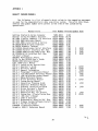
APPENDIX I
HEWLETT PACKARD MANUALS
The following is a list of manuals which relate to the computing equipment
as used for the magnetotelluric data acquistion system. The print date shown,
edition and update number were current at the time of the system being
operational.
Manual^Title
Getting Started A-Series Computer
Decimal^String Arithmetic Routines
HP 1000 L-Series Computer I/O Interface
HP 1000 A600 Reference Manual
HP 1000 A600 Installation & Service
HP 2622A/2623A Display Terminals
HP 2623A Graphics Terminal
HP 12005A Asynchronous Serial^Interface
HP 12006A Parallel^Interface Ref. Man.
HP 12008A PROM Storage Module Ref. Man.
HP 12009A HP-TB Interface Ref. Man.
VIS User's Manual
DOS/RTE Relocatable Library
HP-IB in the HP1000 User's Guide
MACRO/1000 Reference Manual
Edit 1000 User's Manual
RTE-A.1^Installation^Instructions
RTE-A.1 Operator's Guide
RTE-A.1 Utilities Manual
RTE-A.1 General^Information
RTE-A.1 Programmer's Reference Manual
RTE-A.1 File Management Reference Manual
RTE-A.1 LINK Relocating Loader Manual
RTE-A.1 Debug Reference Manual
RTE-A.1 Driver Reference Manual
RTE-A.1 System Design Manual
RTE-A.1 Generation Planning Guide
RTE-A.1 Generator Reference Manual
RTE-A.1 Software Installation Guide
RTE-A.1 Driver Designer's Manual
RTE-A.1 Quick Reference Guide
RTE-A.1 Generation Req. ^for Drivers
RTE-A.1 System Gen.^& Installation Man.
RTE-A.1 LINK User's Manual
RTE-A.1^Index & Glossary
RTE-A.1 Relocatable Libraries Ref.^Man.
RTE-A.1 Primary System Software Install.
RTE-A.1 FCO Utilty Manual
FORTRAN 77 Reference Manual
Graphics 1000-II Reference Manual
Part Number Printed Update Date
5955-8813
02100-90192
02103-90005
02156-90001
02156-90002
02622-90008
02623-90001
12005-90001
12005-90001
12008-90001
12009 90001
12824-90001
24998-90001
59310-90064
92059-90001
92074-90001
92077-90001
92077-90002
92077-90004
92077-90006
92077-90007
92077-90008
92077-90009
92077-90010
92077-90011
92077-90013
92077-90014
92077-90016
92077-90018
92077-90019
92077-90020
92077-90021
92077-90034
92077-90035
92077-90036
92077-90037
92077-90038
92077-90048
92836-90001
92841-90001
39
4/82
10/79
4/82
3/82
3/82
6/81
7/81
1/80
1/80
1/80
1/80
1/83
10/81
12/83
6/83
7/82
2/82
6/83
6/83
2/82
6/83
2/82
7/82
2/82
6/83
6/83
2/82
2/82
2/82
6/83
6/83
2/82
8/83
6/83
6/83
12/83
3/84
12/83
12/81
1/83
3
2
2
2
4/82
3/82
3/82
9/82
1
4
1
1
1
12/83
12/83
1/83
12/83
7/82
1/83
1
12/83
4
1/83
4
1/83
1
2
1/83
12/83
1
1
4/82
7/83
1
APPENDIX 2
POLES & ZEROS FILES
FILE P&Z22::17:4
Ex Channel Preamps
3 I 0 0^** Ex channel ** preamps- No poles, No fudgp's, No zeros, No fudgz's
(-70.07,70.07)^(-186.605,0.0)^(-13.40,0.0)^poles
2.5005E7^fudgp
no zeros
no fudgz's
(-0.01647,0.004934)
(-0.04528,0.01356)
(-0.01647,0.04934)
(-0.7547,0.2258)
(-3.4298,1.0270)
(-17.157,5.1359)
(-54.893,16.441)
(-0.01196,0.01510)
(-0.0329,0.04156)
(-0.1196,0.1511)
(-0.5483,0.69248)
(-2.4924,3.1481)
(-12.469,15.739)
(-39.868,50.365)
1.09685E-7 postamp LP filter 1
6.27717E-6^"^"^"^2
II
3
1.09777E-3
"
II
II
0.484135
"
4
u
n
5
206.664
n
1.2925E+5
"
6
n
II
7
103548E+7
(-7.071E-4,0.0)
(-7.071E-3,0.0)
(-2.1214E-3,0.0)
(-7.071E-2,0.0)
(-0.3536,0.0)
(-1.7678,0.0)
(-7.07,0.0)
(0.0,0.0)
(-7.071E-4,0.0)
(-7.071E-3,0.0)
(-2.1214E-3,0.0)
(-7.071E-2,0.0)
(-0.3536,0.0)
(-1.7678,0.0)
(-7.071,0.0)
(0.0,0.0)
1.0
1.0
1.0
1.0
1.0
1.0
1.0
1.0
postamp HP filter 1
It^II^It
3
It
TI
H
It
TI
It
It
TI
II
5
II
TI
H
TI
"
6
H
7
postamp HP filter zero
Ey Channel Preamps
3 1 0 0^** Ex channel ** preamps- No poles, No fudgp's, No zeros, No fudgz's
(-70.07,70.07)^(-186.605,0.0)^(-13.40,0.0)^poles
2,5005E7^fudgp
no zeros
no fudgz's
(-0.01647,0.004934) ^(-0.01196,0.01510)^1.09685E-7 postamp LP filter 1
(-0.04528,0.01356)
(-0.0329,0.04156) 6.27717E-6^"^"^"^2
If
3
II
(-0.01647,0.04934)
(-0.1196,0.1511)
1.09777E-3
"
n
It
(-0.7547,0.2258)
(-0.5483,0.69248) 0.484135
"
4
H
H
n
5
(-3.4298,1.0270)
(-2.4924,3.1481)
206.664
n
u
(-17.157,5.1359)
(-12.469,15.739)
1.2925E+5
"
6
u
n
7
It
(-54.893,16.441)
(-39.868,50.365)
103548E+7
(-7.071E-4,0.0)
(-7.071E-3,0.0)
(-2.1214E-3,0.0)
(-7.071E-2,0.0)
(-0.3536,0.0)
(-1.7678,0.0)
(-7.07,0.0)
(0.0,0.0)
(-7.071E-4,0.0)
(-7.071E-3,0.0)
(-2.1214E-3,0.0)
(-7.071E-2,0.0)
(-0.3536,0.0)
(-1.7678,0.0)
(-7.071,0.0)
(0.0,0.0)
1.0
1.0
1.0
1.0
1.0
1.0
1.0
1.0
40
postamp HP filter 1
II^It^II^
2
It
It
II
3
II
It
II
II
"
4
II
It
II
II
"
6
II
II
5
7
postamp HP filter zero
Hz Channel Preamps
3 1 0 0^** Ex channel^** preamps- No poles,^No fudgp's,^No zeros,^No fudgz's
(-70.07,70.07)^(-186.605,0.0)^(-13.40,0.0)^poles
2.5005E7^fudgp
no zeros
no fudgz's
(0.5292,0.0)^(-11.14,0.0)^(176.25,0.0)^(-9896.0,0.0)^2.009E7^coil^set^1*
(0.5306,0.0)^(-11.05,0.0)^(179.13,0.0)^(-4449.6,0.0)^9.262E6 coil^set^2*
(-0.01647,0.004934)^(-0.01196,0.01510)
(-0.04528,0.01356)^(-0.0329,0.04156)
(-0.01647,0.04934)^(-0.1196,0.1511)
(-0.7547,0.2258)^(-0.5483,0.69248)
(-3.4298,1.0270)^(-2.4924,3.1481)
(-17.157,5.1359)^(-12.469,15.739)
(-54.893,16.441)^(-39.868,50.365)
1.09685E-7 postamp LP filter 1
6.27717E-6^"^"^"^2
II
IT
3
1.09777E-3
I
0.484135
"
4
5
H
H
H
206.664
II
H
1.2925E+5
"
6
II
ti
II
7
103548E+7
(-7.071E-4,0.0)^(-7.071E-4,0.0)
(-7.071E-3,0.0)^(-7.071E-3,0.0)
(-2.1214E-3,0.0)^(-2.1214E-3,0.0)
(-7.071E-2,0.0)^(-7.071E-2,0.0)
(-0.3536,0.0)^(-0.3536,0.0)
(-1.7678,0.0)^(-1.7678,0.0)
(-7.07,0.0)^(-7.071,0.0)
(0.0,0.0)^(0.0,0.0)
Hx Channel^Preamps
1.0
1.0
1.0
1.0
1.0
1.0
1.0
1.0
postamp HP filter 1
II
11
I
2
3
II
II
II
'
II
U
II
11
II
"
4
5
"
6
7
II
H
postamp HP filter zero
3 1 0 0^** Ex channel ** preamps- No poles, No fudgp's, No zeros, No fudgz's
(-70.07,70.07) (-186.605,0.0) (-13.40,0.0) poles
2.5005E7^fudgp
no zeros
no fudgz's
(0.5298,0.0)^(-11.23,0.0)^(182.70,0.0)^(-3061.0,0.0)^6.0602E6 coil^set^1*
(0.5260,0.0)^(-11.26,0.0)^(173.70,0.0)^(-8541.0,0.0)^1.756E7^coil^set^2*
(-0.01647,0.004934)^(-0.01196,0.01510)^1.09685E-7 postamp LP filter 1
(-0.04528,0.01356)^(-0.0329,0.04156)^6.27717E-6^11^11^"^2
It
3
(-0.01647,0.04934) (-0.1196,0.1511)^1.09777E-3^
II
It
4
(-0.5483,0.69248)^0.484135
(-0.7547,0.2258)
It
It
II
(-2.4924,3.1481)^206.664
5
(-3.4298,1.0270)
It
It
H
6
(-17.157,5.1359)
(-12.469,15.739)^1.2925E+5
It
It
7
(-54.893,16.441)
(-39.868,50.365)^103548E+7
(-7.071E-4,0.0)
(-7.071E-3,0.0)
(-2.1214E-3,0.0)
(-7.071E-2,0.0)
(-0.3536,0.0)
(-1.7678,0.0)
(-7.07,0.0)
(0.0,0.0)
(-7.071E-4,0.0)^1.0
(-7.071E-3,0.0)^1.0
(-2.1214E-3,0.0)^1.0
(-7.071E-2,0.0)^1.0
(-0.3536,0.0)^1.0
(-1.7678,0.0)^1.0
(-7.071,0.0)^1.0
(0.0,0.0)^1.0
41
postamp HP filter 1
II^11^11^
2
It
II
II
3
II
11
II
11
II
II
"
It
4
5
"
6
H
7
postamp HP filter zero
^
Hy Channel Preamps
3 1 0 0^** Ex channel ** preamps- No poles, No fudgp's, No zeros, No fudgz's
(-70.07,70.07) (-186.605,0.0) (-13.40,0.0)^poles
2.5005E7^fudgp
no zeros
no fudgz's
^(0.5464,0.0)^(-10.66,0.0)^(183.90,0.0) (-9361.0,0.0)^1.935E7 coil^set^1*
(0.5431,0.0)^(-10.69,0.0)^(182.30,0.0) (-7694.0,0.0)^1.581E7 coil^set 2*
(-0.01647,0.004934)
(-0.04528,0.01356)
(-0.01647,0.04934)
(-0.7547,0.2258)
(-3.4298,1.0270)
(-17.157,5.1359)
(-54.893,16.441)
(-0.01196,0.01510)
(-0.0329,0.04156)
(-0.1196,0.1511)
(-0.5483,0.69248)
(-2.4924,3.1481)
(-12.469,15.739)
(-39.868,50.365)
1.09685E-7 postamp LP filter 1
"
2
"
"
6.27717E-6
u
u
9
3
1.09777E-3
II
II
II
4
0.484135
II
II
II
5
206.664
u
u
6
1.2925E+5
II
II
7
103548E+7
(-7.071E-4,0.0)
(-7.071E-3,0.0)
(-2.1214E-3,0.0)
(-7.071E-2,0.0)
(-0.3536,0.0)
(-1.7678,0.0)
(-7.07,0.0)
(0.0,0.0)
(-7.071E-4,0.0)
(-7.071E-3,0.0)
(-2.1214E-3,0.0)
(-7.071E-2,0.0)
(-0.3536,0.0)
(-1.7678,0.0)
(-7.071,0.0)
(0.0,0.0)
1.0
1.0
1.0
1.0
1.0
1.0
1.0
1.0
postamp HP filter 1
u^It^II^2
3
II
II
II
II
It
u
9
"
u
4
II
II
Il
II
"
6
II
5
7
postamp HP filter zero
NOTE: * Denotes that these values will need to be replaced with new poles
and fudgp's when new H channel pre-preamps are built.
^
42
c(>
APPENDIX 3
MT SYSTEM BOOT FILE
FILE BCF01::16:4
0001 EC
0002 $L
0003 EC
0004 *
0005 * DEFINE SYSTEM AND SNAP FILES
0006 SY,'OUTPUT:LA:16
0007 SN,SNAP:LA:16
0008 *
0009 MC,18
0010 MC,17
0011 MC,19
0012 MC,20
0013 MC,16
0014 *
0015 * DEFINE INITIALLY RP'ED PROGRAMS
0016 RP,D.RTR
0017 *
0018 RP,COMND
0019 *
0020 RP,FMGR
0021 ST,WE,LC,OM
0022 *
0023 * LINK EDIT TO ALLOW EDITING SYSTEM FILE
0024 *
0025 LK,EDIT
0026 *
0027 LK,FC
0028 *
0029 LK,LINK
0030 RP,HELP
0031 RP,CURNT
0032 RP,UPDAT
0033 RP,FILES
0034 RP,STATS
0035 RP,AQUIR
0036 RP,INITL
0037 RP,PUFT
0038 RP,FFT
0039 RP,TENSE
0040 RP,MTPLT
0041 RP,CHEK
0042 RP,MAGTL
0043 *
0044 * END RP/LK PHASE
0045 END
0046*
0047 DEFINE SWAP FILES
0048 SW,SWAP:SW:-18
0049 *
0050 END
43
LK,
APPENDIX 4
SYSTEM BOOT FILE
FILE SYSTEM::16:4
0001
0002
0003
0004
0005
0006
0007
0008
0009
0010
0011
0012
0013
0014
0015
0016
0017
0018
0019
0020
0021
0022
0023
0024
0025
0026
0027
0028
0029
0030
0031
* EC
*
* DEFINE SYSTEM AND SNAP FILES
SY,PRMSYS
SN,SNAP
*
MC,18
MC,17
MC,16
*
* DEFINE INITIALLY RP'ED PROGRAMS
RP,D.RTR
*
RP,COMND
*
RP,FMGR
ST,WE,LC,OM
*
* LINK EDIT TO ALLOW EDITING SYSTEM FILE
*
LK,EDIT
*
LK,LINK
*
* END RP/LK PHASE
END
*
DEFINE SWAP FILES
SW,SWAP:SW:-18
*
END
44
APPENDIX 5
LOGICAL UNIT (LU) TABLE
LU^DEVICE
16^7908A Disc cartridge 16
17^7908A Disc cartridge 17
18^79081-\ Disc cartridge 18
19^7908A Disc cartridge 19
20^7908A Disc cartridge 20
24^7908A Tape drive
30^Phoenix A-to-D converter
31^SPO-1 Programmable oscillator
32^XDM-1 Multiplexer
HP
^
FIG.1 MT SYSTEM BLOCK DIAGRAM
POWER
SUPPLY
^
^
POST-AMP
FLITE-TRONICS
^
^
POWER SUPPLY
INVERTER
SET OF 3
MAGNETIC
INDUCTION
COILS
MAGNETIC
PRE-AMPS
POST-AMPS
Et FILTERS
(BM R)
2 PAIRS
OF
Cd— Cd Cl 2
POTS
PROGRAMMABLE
OSCILLATOR (BMR)
PHOENIX
A- D
CONVERTER
-4111F--1110'"
HP7908 A
H P1 000
PHOENIX
INTERFACE
DISC
MAG
A600
CPU
TAPE DRIVE
ELECTRIC
PRE-AMPS
TEST
^
SIGNAL ^
CALIBRATOR
^
GENERATOR
CRO
^
MUX (BMR)
^
VDU Et
PRINTER
HP 2623A
rumns
FIG.1 KEY
Magnetic induction coils
Cd-CdCl z pots
Signal generator
Magnetic Preamplifiers
Electric Preamplifiers
Calibrator
Postamplifier power supply
Postamplifiers and filters
CRO
Phoenix A-to-D converter
Phoenix interface
Programmable oscillator
HP 1000 A600 CPU
VDU and printer
Disc and mag. tape drive
:
:
:
:
:
:
:
:
:
:
:
:
:
:
:
Geotronics model MTC-4SS
Geotronics model MTE-2
Hewlett Packard model 3300A
Geotronics model MTH-4
Geotronics model MTE-4
Geotronics model MTE-4
BMR construction
BMR design and construction
Tektronix model 5113
Phoenix model 6915-3754
Phoenix model PDI Std. Interface
BMR design and construction
Hewlett Packard model A600
Hewlett Packard model 2623A
Hewlett Packard model 7908A
47
^
cO
FIG.2 MT SYSTEM RACK POSITIONS
SIG. GENERATOR
POST AMP POWER SUPPLY
PATCH BOARD
CRO
PROGRAMABLE OSCILLATOR
POST AMPS
HP A600
CPU
E·PRE AMPS
HP7908A
DISC & TAPE DRIVE
H·PRE AMPS
A·DINTERFACE
CALIBRATOR
PHOENIX A· D CONVERTER
24V
DC POWER SUPPLY
MULTIPLEXER
27/N/20
48
~!