1
MODELS
VSP6020, VSP2050, VSP4030 & VSP12010
High Power Switching DC Power Supplies
Instruction Manual
TABLE OF CONTENTS
SECTION
DESCRIPTION
PAGE NO.
1
TEST INSTRUMENT SAFETY
1
2
GENERAL INFORMATION
2
3
INSTALLATION
6
4
OPERATING INSTRUCTION
10
5
MAINTENANCE
19
6
REMOTE INTERFACE
21
7
CUSTOMER SUPPORT
63
8
WARRANTY INFORMATION
64
9
SERVICE INFORMATION
65
Section 1
Test Instrument Safety
WARNING
Normal use of test equipment exposes you to a certain amount of danger from electrical
shock because testing must sometimes be performed where exposed voltage is present.
An electrical shock causing 10milliamps of current to pass through the heart will stop most
human heartbeats. A Voltage as low as 35 volts dc or ac (rms.) should be considered
dangerous and hazardous since it can produce a lethal current under certain conditions.
Higher voltages pose an even greater threat because such voltage can more easily produce
a lethal current. Your normal work habits should include all accepted practices to prevent
contact with exposed high voltage and to steer current away from your heart in case of
accidental contact with high voltage. You will significantly reduce the risk factor if you know
and observe the following safety precaution.
1. Don’t expose high voltage needlessly. Remove housings and covers only when necessary.
Turn off equipment while making test connections in high voltage circuits. Discharge high
voltage capacitors after removing power.
2. If possible, familiarize yourself with the equipment being tested and the location of its high
voltage points. However, remember that high voltage may appear at unexpected points in
defective equipment.
3. Use an insulated floor material or a large, insulated floor to stand on and an insulated work
surface on which to place equipment and make certain such surfaces are not damp or wet.
4. Use the time proven “one hand in the pocket” technique while handling an instrument probe.
Be particularly careful to avoid contacting a nearby metal object that could provide a good
ground return path.
5. When testing ac powered equipment, remember that ac line voltage is usually present on
some power input circuits such as the on-off switch, fuses, power transformer etc. any time
the equipment is connected to an ac outlet, even if the equipment is turned off.
6. Some equipment with a two-wire ac power cord, including some with polarized power plugs,
is the “hot chassis” type. This includes most recent television receivers and audio equipment. A plastic wooden cabinet insulates the chassis to protect the customer. When the
cabinet is removed for servicing, a serious shock hazard exists if the chassis is touched. Not
only does this present a dangerous shock hazard, but damage to test equipment. Always
connect an isolation transformer between the ac outlet and the equipment under test. The
B&K Precision Model TR-110 or 1604A Isolation Transformer or Model 1653A or 1655A AC
Power Supply is suitable for most applications. To be on the safe side, treat all two-wire ac
equipment as “hot chassis” unless you are sure it is isolated chassis or an earth ground
chassis.
7. On test instruments or any equipment with a 3-wire ac power plug, use only a 3-wire outlet.
This is a safety feature to keep the housing or other exposed elements at earth ground.
8. B&K Precision products are not authorized for use in any application involving direct contact
between our product and the human body or for use as a critical component in a life support
device or system. Here “direct contact” refers to any connection from or to our equipment
via any cabling or switching means. A “critical component” is any component of a life support device or system whose failure to perform can be reasonably expected to cause failure
of that device or system or to affect its safety or effectiveness.
Never work all alone. Someone should be nearby to render aid if necessary. Training
in CPR (cardiopulmonary resuscitation) first aid is highly recommended.
1
Section 2
General information
2.1
INTRODUCTION
2.2
FEATURE
2.3
MARKINGS
2.4
INTERFACE
2.5
SPECIFICATION
2.6
ORDERING INFORMATION
2.1
INTRODUCTION
The VSP SERIES power supplies are designed to deliver power in constant
voltage and constant current mode by switch mode conversion in sleek 1U high
cabinet and in a 19’’ rack construction.
This series comprises the two device soft switching technology that yields
very high efficiency of conversion for dc-to-dc converter part. Also it comprises
power factor correction circuity, which shapes the input current to follow the voltage
to maintain almost unity power factor at full load, and limits the current harmonics in
the input line.
It provides the user the option of isolated analog voltage, current and resistance programming with built-in isolation amplifiers. It gives the option to monitor the
isolated signals with the option to change either from 0 to 5 Volts or from 0 to 10
Volts, for output voltage and current from 0 to full-scale level. It provides the display of
the output voltage, over voltage set level and current with 3-digit LED displays.
Piggyback series pass device ensures the ripple and noise levels to very low values.
Current sharing facility in the module gives the advantage to increase the power with
ease and the vents in the front and the rear enables it with absolutely zero stacking.
The module can be switched on/off through the front panel ON/OFF switch or remote switch on rear panel.
VSP series provides digital interface options for remote programming from
PC. The digital interface provides 12-bit resolution for control as well as monitoring
the output.
2
Some of the features of the power supply are listed below:
2.2
FEATURES
§
§
§
§
§
§
§
§
§
§
§
§
§
§
§
§
§
§
§
§
§
MAINS OPERATED, WITH WIDE INPUT RANGE.
POWER FACTOR CORRECTED INPUT.
ISOLATED D.C. OUTPUT.
1200-WATT OUTPUT POWER
CONSTANT VOLTAGE OPERATION FROM 0 TO FULL-SCALE LEVEL.
CONSTANT CURRENT OPERATION FROM 0 TO FULL-SCALE LEVEL.
OVER VOLTAGE CONTROL FACILITY.
REMOTE SENSING FACILITY.
PARALLELABLE CURRENT SHARING OUTPUT.
HIGH OVERALL EFFICIENCY – 80% TYPICAL.
VERY LOW OUTPUT RIPPLE AND NOISE.
INPUT EMI FILTERING TO MEET EN55022 CLASS A.
20 MILLISECOND HOLD-UP TIME.
TWO FRONT PANEL DPMS. FOR V / O.V AND I.
MULTI TURN POTENTIOMETERS FOR V, O.V AND I SET.
FRONT PANEL OUTPUT TERMINALS FOR MONITORING.
SLEEK, 1U HIGH, 19 INCH RACK CONSTRUCTION.
INTERNAL FORCED AIR COOLING WITH ZERO STACKING.
ISOLATED ANALOG VOLTAGE, CURRENT AND RESISTANCE PROGRAMMING
AND MONITORING.
REMOTE ON/OFF FACILITY.
RS232/ GPIB/ INTERFACE.
2.3
MARKINGS
The unit has the name PROGRAMMABLE PFC DC SUPPLY written clearly
on the top of the front panel. The Model Number and ratings are also clearly written
on the front panel. The ratings are clearly written on the rear panel, just near the
output terminals.
2.4
INTERFACE
The unit has both local as well as remote controls. For Remote operation, the
series offers analog as well as digital interface or both. Both RS 232 or GPIB digital
interfaces can be provided.
3
2.5
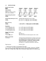
SPECIFICATIONS
Output Specification
Model
Power
Output Voltage
Output Current
Ripple rms. (10Hz to 1MHz)
Noise (10Hz to 20MHz)
Programming Resolution
Voltage
Current
VSP6020*
1.2KW
0–60V
0–20A
<10mV
<45mVpp
VSP2050*
1.2KW
0–20V
0–50A
<15mV
<45mVpp
VSP4030*
1.2KW
0–40V
0–30A
<10mV
<45mVpp
VSP12010*
1.2KW
0–120V
0–10A
<20mV
<45mVpp
(Digital Interface), LSB (not LED displays)
20 mV
10 mV
10 mV
100 mV
10 mA
20 mA
10 mA
10 mA
Output Programming Accuracy
Voltage
Current
(Analog Programming 0 To 5V & 0 To 10V)
0.5 % of F. S. ± 1 Digit (spec. for all VSP models)
0.5 % of F. S. ± 1 Digit (spec. for all VSP models)
Meter Accuracy
Voltage
Current
+/- 0.2% of F.S. +/- 3 Digit. (spec. for all VSP models)
+/- 0.2% of F.S. +/- 3 Digit. (spec. for all VSP models)
Regulation
CV Line Regulation (mV)
CC Line Regulation (mV)
CV Load Regulation (mA)
CC Load Regulation (mA)
0.1 % of F.S (spec. for all VSP models)
0.1 % of F.S (spec. for all VSP models)
0.1 % of F.S (spec. for all VSP models)
0.1 % of F.S (spec. for all VSP models)
Output Specification
Stability
Efficiency<
Transient Response
0.05%
80% Minimum
250 microseconds for load change from 40% to 90%
Mode Of Operation
Local Mode
Digital Interface
Through front panel potentiometer for voltage, current and
over voltage and Push switch for Output ON/ OFF control.
Remote Mode Interface Analog programming of voltage
and current.Voltage: 0 - 5 volts or 0 – 10 volts for output
voltage and current, selection through DIP-switch.
Resistance: 0 – 4.85k ohms from 0 to full-scale level.
RS-232 / GPIB
* = Specification also apply to corresponding GPIB model
F.S = Full Scale. Full scale will be different for each model. Example: If you have a VSP2050
and you are measuring the voltage meter accuracy, the meter can not off more than 0.3V
(20V + 0.2% +3 digit). Note: 3 digits refferes to the power supply displays least significant digit.
4
Protections
Over voltage protection
Over temperature protection
Programmable through POT in local mode and through
digital interface in remote mode.
Through 90 °C. thermal switch on heat sink.
Input specifications
Mains Input Range
Input Frequency
Input Power Factor
Inrush Current
95Vac to 264Vac.
47 To 63 Hz
0.99 On Full Load At Nominal Input.
Limited By NTC
Operating Environment
Temperature
Relative Humidity
Storage Temperature
Warm-up Time
0 - 50°C
< 80% rh – non condensing
- 20°C. to + 70°C.
15 minutes.
Safety Standards
EMI Filtering
Safety Class
EN55022 Class-A
EN60950
Mechanical Specifications
Weight (approx.)
Dimensions (WxHxD)
Dimensions with rubber feet
13.7lbs. (6.2 KG.)
19 x 1.75 x 18” (483 x 44.5 x 457mm)
19 x 2.13 x 20” (483 x 54 x 457mm)
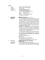
2.6 ORDERING INFORMATION:
MODEL NO
DESCRIPTION
VSP6020
60V, 20A power supply with opto-isolated analog interface and RS-232
VSP6020GPIB 60V, 20A power supply with opto-isolated analog interface and GPIB
VSP4030
40V, 30A power supply with opto-isolated analog interfaceandRS-232
VSP4030GPIB 40V, 30A power supply with opto-isolated analog interface and GPIB
VSP2050
20V, 50A power supply with opto-isolated analog interface and RS-232
VSP2050GPIB 20V, 50A power supply with opto-isolated analog interface and GPIB
VSP12010
120V, 10A power supply with opto-isolated analog interface and RS232
VSP12010GPIB120V, 10A power supply with opto-isolated analog interface and GPIB
5
Section 3
Installation
3.1
INTRODUCTION
3.2
UNPACKING
3.3
INPUT POWER REQUIREMENTS
3.4
SYSTEM CONFIGURATION
3.5
INSTALLATION
3.6
TEST EQUIPMENT REQUIREMENTS
3.1
Introduction
VSP series power supply is configured, calibrated and tested prior to shipment.
This unit is therefore ready for immediate use upon receipt. The initial physical inspections should be made to ensure that no damage has been sustained during shipment.
3.2
Unpacking
Inspect the shipping container before accepting it from the carrier. If damage to
the container is evident, remove the instrument from the container and visually inspect
it for damage to the instrument case and parts.
If damage to the instrument is evident, a description of the damage should be
noted on the carrier’s receipt and signed by the driver or carrier agent. Save all shipping
containers and material for inspection.
Forward a report of any damage to the factory or the agent through which the unit
is procured.
Retain the original packing container if subsequent repackaging for return to the
factory were required. Repackaging is straightforward and is essentially the reverse of
the unpacking. Only subassemblies need to be repackaged for reshipment, use the
original containers.
Remove the Source module from its shipping container and inspect for any damage to the front panel and display module. Also check for any optional parts which may
have been ordered by you. If the switch or display is heavily damaged or is broken then
DO NOT switch-ON the instrument.
Check the rear of the instrument for damage to Sockets or Fuse Holders. Inspect also the POWER-ON switch on the front panel.
6
3.3
Input Power Requirements
The Model VSP power supply is configured at the factory to operate from 95-264
VAC at 47-63 Hz power line.
3.4
System Configuration
The Model VSP series power supply comes in ready to use fashion and does not
require any configuration in the field for operation in the local mode. For analog interface
refer to the connector details for the connections.
3.5
Installation
1. AC Input Power Connection
Connect a 3-pin power mains cord to the available line supply. Before connecting line ensure the following:
a) The available line supply is compatible to your unit.
b) The available line supply point is capable of supplying the maximum peak current
and power.
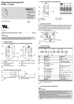
2. Load Connections
Refer fig.3.1A for load connection in local and remote sensing mode, the unit has
5mm brass studs on the rear panel for load connections for model up to 30A. The bus
bar is provided from 30A onwards.
For remote sensing and the current sharing option it is provided with separate 6
way terminal block. This is required if your load is far away & regulation needs to be
maintained at load terminals.
An output cable should be able to handle the full load current and maximum
voltage and power under worst case conditions of temperature, humidity, mechanical abuse, and effects of long term aging.
3. Analog Interface Connections
A 25 pin D type connector & DIP switch is provided for remote analog interface
to the unit. There is 8 pin DIP switch associated with the function of analog interface.
Refer to section 4.3.5 of chapter 4 for switch settings.
4. Turn-On
Switch the POWER ON switch to the ON position. Soon the DPM will be turned
on & the output voltage & current are displayed, if output on-off switch is in ON position.
Voltmeter should display the voltage set by voltage control.
Check the current meter. It must show zero (very low) current under no load. If
not then please switch off the unit and call the service personnel.
For details of TURN ON CHECK refer section 4.5 of CHAPTER 4.
7
3.6
Test Equipment Requirements
The following instruments will be required to test the complete installation of the
unit.
1). A four and half digit or better digital multimeter for verifying the voltage and current
output of the unit.
2). A 20 MHz dual channel oscilloscope for verifying the Ripple in Output of the Source.
3). A Resistive load or an Electronic Load to take an input to suit the maximum
output from the unit depending on the model and capacity of the channel of the
Source.
8
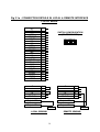
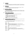
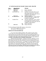
Fig 3.1a : CONNECTION DETAILS IN LOCAL & REMOTE INTERFACE
LOCAL MODE
1
2
3
4
5
6
7
8
9
10
11
12
13
14
15
16
REMOTE ON/OFF 17
AMX
18
VMX
19
AGND3
20
NC
21
VPSET
22
VMSET
23
IPSET
24
IMSET
25
NC
NC
VPROGI
VPIN
VPROGR
AGND3
NC
NC
IPIN
IPROGI
IPROGR
NC
NC
NC
+12V
AGND3
+S
+
-S
NC
CS BUS
SWITCH CONFIGURATION
(ON REAR PANEL)
12345678
O
N
1
2
3
4
5
6
+S
+
-S
NC
CS BUS
Output +VE
1
2
3
4
5
6
Output +VE
Output -VE
Output -VE
LOAD
LOCAL SENSING
LOAD
REMOTE SENSING
9
Section 4
Operating instruction
4.1
INTRODUCTION
4.2
FRONT PANEL DESCRIPTION
4.3
REAR PANEL DESCRIPTION
4.4
POWER ON CHECK
4.5
OPERATING INSTRUCTIONS IN LOCAL MODE
4.6
OPERATING INSTRUCTIONS IN ANALOG REMOTE INTERFACE
4.7
OPERATING INSTRUCTIONS IN DIGITAL INTERFACE
4.8
TRIP INDICATIONS
4.1
INTRODUCTION
The VSP series Model is a variable switch mode power supply to provide wide
range of DC supply from 0 to full-scale specified voltage. This chapter explains the
operating procedure of the unit. The operation is very simple by providing POT control
for voltage, current limit and over voltage protection limit and 8 way DIP switch along
with 25 Pin D type connector for the remote programming interface.
Optional RS232 interface or GPIB interface can be provided as per the order
placed. In case of RS232 interface, a slide switch no. 7 on 8 pin DIP switch array on the
rear panel facilitates either LOCAL/ RS232 communication interface or Analog programming.
The unit is internally fan cooled. The air inlet vents are provided on the front panel.
The air outlet is a rectangular slotted area on the 1U high rear panel, and is located
between the A.C. input and D.C.output connectors.
The instrument front panel and rear panel are described first in detail, explaining the layout, identification, function and usage of each item on the panel. The Turnon sequence and the procedure to use the major functions and operation of unit in
digital interface are also explained. At the end all the ALARM indications, errors and
warning signals are explained. In the same section procedures to clear the TRIP and
ALARM conditions are discussed.
10
4.2
FRONT PANEL DESCRIPTION
Figure 4.1 shows layout of front panel. On the front panel following controls and
indicators are provided.
1.
2.
3.
4.
5.
6.
7.
8.
9.
Main ON/OFF switch with neon indication.
3 digit display for Voltage/ Set Voltage/ Set Over Voltage indication
3 digit display for Current/ Set Current indication.
10 turn POT for voltage control.
10 turn POT for current control.
10 turn POT for over voltage protection control.
Push switch to view set parameters in SET mode.
Latch type Push switch for Output ON/OFF control.
LED indications for CV, CC, Output ON, Trip, Remote, V set, I set, O/V set and
Set mode.
- The display shows 3 digit value for voltage and current parameters. The resolution of
indication is 0.1 volt and 0.1 amp for voltage and current parameters. The display is
used to show actual output voltage and current or to show set values of voltage, over
voltage and set current limit in the set mode. The set mode is activated using Set key
during output OFF condition.
- CV LED indicates the constant voltage operation of power supply.
- CC LED indicates constant current operation of power supply.
- TRIP LED becomes ON either for over voltage trip condition or for over temperature
trip condition.
- Output ON/OFF can be controlled by push button switch (latch type) and LED turns
ON if output is available.
- Remote LED is provided for the digital interface option. It lights up when the power
supply is controlled by external digital interface.
- To view the set values of POT on the display press the SET key. Also LED’s for
each POT and common SET MODE Led is provided.
- Also monitoring terminals of output are provided on front panel so that user can verify
the output with calibrated meter. Additional earth terminal is also provided on front
panel.
4.3
REAR PANEL DESCRIPTION
The rear panel of the unit is shown in fig 4.2. The mains input connection is
made through a mains cord and is located on the right side of the unit at the rear.
A 20A fuse of type ’F’ is used for line input range 95Vac to 264Vac,) provided at input.
At the center are the oval shaped ventilation slots for air exhaust, for D.C. output 5mm
brass studs or bus bars (as per the current specifications) are provided, next to
it is 6 way terminal block for remote sensing and current share bus. Further is the 25
pin D-type connector for analog interfacing & the associated 8 pin DIP switch for
selection of analog mode operation and it’s associated modes of operation. Above the
25 pin D-type connector the provision is made for digital interface connection, which
can be either GPIB or RS232.
11
12
13
1
14
15
6
2
16
12
7
3
11
4
8
17
10
17
19
20
9
17
18
5
21
22
24
26
23
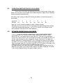
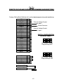
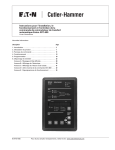
Sr. No.
1
2
3
Description
Input Line Cable
Input Fuse
Input R. F. Filter
4
5
6
7
8
9
10
11
12
13
VSP-PFC-1.2KW-1103D, PCB
Input ON/OFF Switch
Heat Sinks
PFC Choke
DC DC Converter Transformer
VSP-DPM-CONT-1204D, PCB
VSP-FAN-CNT-1103C, PCB
VSPDDC-1.2KW-0704E, PCB
Digital Interface PCB
Output Power Terminals
Sr. No.
14
15
16
17
18
19
20
21
22
23
24
25
26
25
26
Description
Output Sense Terminals
Analog Interface Connector
DIP switches for Analog Interface
selection
Cooling Fans
SBC-IEB-0504A, PCB (For GPIB)
VSP-POT-IMON-0604A, PCB
VSP-FPDAC CONV-0604A, PCB
Voltage Monitoring Terminals
VSP-DPM-1UFP-0604D, PCB
Potentiometers for control
SET, ON/OFF switch Assembly
Earth Terminal
Handles
GENERAL ASSEMBLY DRAWING OF VSP SERIES POWER SUPPLY
13
4.3.1
LINE INPUT
The mains input range is clearly indicated on rear panel. The unit comes standard with a U.S. standard plug and a mains input rating of 95VAC to 265VAC, 50/60Hz.
4.3.2
INPUT FUSE
This fuse protects the unit against short circuits and over loading. The 20A
fuse of type ’F’ is used for line input range 95Vac to 264Vac.
4.3.3 DC OUTPUT TERMINALS
VSP models with upto 30 amp output ratings have a pair of 5mm brass studs is
provided on the rear panel. Models above 30 amps have bus bars are provided. Output
polarity is shown near the terminal.
4.3.4
REMOTE SENSE CONNECTOR
6 Way terminals block is provided for remote sensing and current
share option.
1. +S: - Positive Sense terminal for remote sensing.
2. +Output: - Positive DC output terminal.
3. -Output: - Negative DC output terminal.
4. -S: - Negative Sense terminal for remote sensing.
5. NC
6. CS Bus: - Current share bus for parallel operation.
4.3.5
ANALOG INTERFACE CONNECTOR (Reference Fig. 4.1a and 4.1b in back of
manual)
25 Pin D type connector is provided for remote analog interface, it is factory set
to operate through the front panel controls.
Pin no. 1:
Pin no. 2:
Pin no. 3:
Pin no. 4:
Pin no. 5:
Pin no. 6:
Pin no. 7:
Pin no. 8:
Pin no. 9:
Pin no.10:
Pin no.11:
Pin no.12:
Pin no.13:
N.C.
N.C.
VPROGI-1 mA (typical) Current source for voltage programming.
VPIN - Input for voltage programming.
VPROGR - Resistance programming (0 to 4.85KOhms for full-scale voltage)
AGND3 - Common terminal for remote programming.
N.C.
N.C.
IPIN - Input for Current programming.
IPROGI- 1mA (typical) Current source for Current programming.
IPROGR - Resistance programming (0 to 4.85KOhms for full-scale current)
N.C.
N.C.
14
Pin no.14:
Pin no.15:
Pin no.16:
Pin no.17:
Pin no.18:
Pin no.19:
Pin no. 20:
Pin no. 21:
Pin no. 22:
Pin no. 23:
Pin no. 24:
Pin no. 25:
4.3.6
N.C.
+12 V- Remote on/off relay supply +ve.
AGND3 - Common terminal for remote programming.
Remote On/Off - Remote on/off relay.
AMX- Output Current monitoring. (Factory set to 0 to 5 volts for full scale)
VMX - Output Voltage monitoring. (Factory set to 0 to 5 volts for full scale)
AGND3 - Common terminal for remote monitoring.
N.C.
VPSET - External programming option set for output voltage.
VMSET -External-monitoring option set for monitoring the output voltage.
IPSET - External programming option set for output current.
IMSET - External monitoring option set for current.
DIP SWITCH DETAILS.
DIP Switch is provided on the rear panel to facilitates remote analog interface as
well as local mode interface in the power supply by just changing the switch positions
Switch no. 1 & 2 are associated with voltage programming
Switch no. 3 & 4 are associated with current programming
Switch no. 5 is associated with 0-5V & 0-10V programming
Switch no. 6 is associated 0-5V & 0-10V monitoring
Switch no. 7 is Local/RS232 and Analog interface selection
Switch no. 8 is associated with remote ON-OFF.
4.3.7
DIGITAL COMMUNICATION INTERFACE (optional)
Digital communication interface either GPIB or RS-232 interface can be incorporated with the system as per the order placed. As per the ordered digital communication interface, the slots are available on the rear panel
The slide switch no. 7 on 8 pin DIP switch array selects the LOCAL/RS232 or Analog
interface & 9 pin D-Type connector is provided on rear panel to connect the unit to PC.
NOTE: Refer Chapter 5 For Details Of Digital Communication Interface.
4.4
POWER ON CHECK
Keep the DIP switch settings for local mode operation. (Refer to 4.5)
After switching ON the unit, the display will show the actual voltage and current at the
output if output ON/OFF switch is in pressed position. If the switch is in OFF position
then the output voltage goes to 0V & displays zero. Also LED associated with key
shows the condition of output. If TRIP LED is ON then display show zero values and
LED associated with ON/OFF key remains off.
15
4.5
OPERATING INSTRUCTIONS IN LOCAL MODE
These are the instructions for operating the source in local mode. Initially after
Power ON Unit work in local mode.In local mode the power supply can be controlled
through front panel potentiometers.
Also Refer to the settings of 8Way DIP Switch provided on rear panel to operate in
Local mode.
Switch No. 1
Position
On
2
On
3
On
4
On
5
On
6
OFF
7
On
8
On
Refer fig. 3.1a for connection details in local & remote interface
Normally user can vary the V SET POT to change the output voltage while working
in constant voltage mode operation. I SET POT is used to set the output current
while working in constant current mode operation.
4.5.1
SET MODE OPERATION IN LOCAL MODE
User can view the set parameters using set mode operation before
turning the output ON. To enter the SET mode, switch off the ON/OFF switch.
When SET key is pressed for the first time then SET LED turns ON and display
shows OVP value and OVP POT LED keeps on flashing. In this mode the OVP POT
can be used to change the over voltage limit. On pressing the SET key again the
display shows the set voltage and VSET POT LED keeps on flashing. In this mode
the VSET POT can be used to change the output voltage. On pressing the SET key
again the display shows the set current and ISET POT LED keeps on flashing. In this
mode the ISET POT can be used to change the output current.
Set mode operation ends after pressing SET key fourth time & displays zero if the
output on / off switch is off. At any instant, while in set mode, if output on / off switch
is pressed the display displays the output voltage & current.
16
4.6
OPERATING INSTRUCTIONS IN ANALOG REMOTE INTERFACE
The Remote analog interface is Provided to control the power supply with
external analog signals.Before using the interface check the type of digital interface
provided with the system.
A slide switch no. 7 on 8 pin DIP switch array is provided at the rear panel to bypass
digital and front panel pot controls. Ensure the position of slide switch is in off
position when operating with external analog controls.
When GPIB interface is used then internal adjustment is required to bypass the GPIB
interface. Refer to GPIB section of Chapter 6.
Following are the positions of switches for the operating the source in remote mode
by external analog voltage and resistance.
4.6.1
Voltage Programming
Apply the input programming voltage of 0 to 5Volts or 0 to10 Volts between pin 4
& common control pin 6 of 25 pin D type connector for voltage programming & for
current programming between 9 & 6 (common control pin) of 25 pin D-Type connector.
8 pin DIP switch on rear panel:
Switch No.
1
2
3
Position
Off Off
Off
4
Off
5
6
7
off
8
On
5 = ON for 0-5V programming
5 = OFF for 0-10V programming
6 = OFF for 0-5V monitoring
6 = ON for 0-10V monitoring
Refer fig. 4.1a for remote voltage and current programming and monitoring
It also explains load connections required in this mode.
Note: Factory set for 0 to 5 volts for full scale output programming and monitoring.
4.6.2 Resistance Programming
For resistance programming standard resistor used is 4.85KOhms.
Following shows the DIP switch configuration required in this mode & explains the
connection of the resistor to the 25 pin D-type connector.
8 pin DIP switch on rear panel:
Switch No.
1
2
3
Position
Off On
Off
4
On
6 = OFF for 0-5V monitoring
6 = ON for 0-10V monitoring
17
5
On
6
7
off
8
On
Refer figure 4.1b for external resistance programming 0 to 4.85kohms for full
scale voltage and current . It also shows the load connections required in this mode.
As shown in the figure for Voltage Control connect the resistance of 4.85 K ohms at
pin 4 & common control pin 6 of 25 pin D Type connector & for Current control
connect resistance between pin 9 & pin 6 (common control pin) of 25 pin D Type
connector.
4.6.3
Remote ON/OFF:
A 25 pin D type connector & DIP switch is provided for remote analog interface to
the unit. There is 8 pin DIP switch associated with the function of analog interface.
SW no. 8 on the rear 8 pin DIP switch is Remote ON/OFF control & must be always on
for terminal voltage ON when operated from the local controls.
For the remote control keep SW no. 8 OFF and connect switch across pin no. 16 &
17 of 25 pin D type connector.
4.7
OPERATING INSTRUCTIONS IN DIGITAL INTERFACE
To enable remote interface, the command for system to enter remote mode
must be entered through remote P.C. This will cause the remote LED on front panel
to glow; now no key on front panel will be detected. However the display will be
updated to indicate the entered value.
In GPIB interface proper address must be given.
To change the output voltage while working in constant voltage mode operation
or to set the output current while working in constant current mode operation, user
has just to enter command (as specified in chapter 5) through remote PC. There are
simple commands to take the unit either in remote or local mode. The status of the
power supply can be easily read using specific commands. The output can be
turned ON or OFF as per requirements. Output ON is indicated by ON LED on the
front panel. Also the over voltage limit can be set. Whenever the output voltage
exceeds this maximum limit the trip condition occurs thereby resetting the output.
The command summary is given in detail in chapter 5.
4.8
TRIP INDICATIONS
The VSP series power supplies has provision of Over Voltage & Over Temperature protection. If at any time one of these conditions occurs, the unit will be
tripped. This means that the output voltage is made to be zero. This condition is
indicated by the Trip LED blinking.
4.8.1
RESETTING THE TRIP CONDITION
Assess as to why the trip has occurred. Then isolate the fault e.g., over voltage
trip condition can be reset by lowering the output voltage than OV trip level & then
toggling the input power will reset trip condition.
For resetting the over temp condition allow some time for cooling the heat
sinks to change the status of thermal switch.
18
Section 5
Maintenance
5.1
INTRODUCTION
5.2
PREVENTIVE MAINTENANCE
5.3
SERVICE INFORMATION
5.1
Introduction
This chapter contains the problems that may occur in the field in the event
of long use. The procedure to test the unit is explained under the proper section.
The individual is advised to use the correct procedure provided for the
purpose of operating the particular sequence to set proper voltages and current
required to test the proper working of the unit.
This unit has few boards and interconnections and the reliability is very
high. However, if a failure occurs the user himself might be able to fix the unit by
following the remedies given under particular complaint.
Read the manual completely in order to understand your unit better.
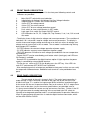
5.2
Preventive Maintenance
Please follow the following preventive steps to ensure the proper operation of your
instrument.
* Allow enough natural cooling (ventilation) around the unit.
* Avoid keeping tools, equipment etc. on the top cover.
* Keep the working area neat and clean always.
* Do not exceed the input/output limits at any time.
5.3
Complaints and Service Information
Some of the common problems that may occur and the remedy to put back
the instrument back in to a working condition as fast as possible are given below:
19
When the unit is not turning ON.
Check if the power ON/OFF switch is turned ON. Check whether fuse
mounted on the rear panel is OK? If fuse is good then check the power cord. Please
make sure that the power cord connecting to the unit is properly connected. Please
also check the mains switch. Check the switch 8 on rear panel, it must be always in
ON position for terminal voltage ON.
When the Trip LED turns On and output turns OFF
Check the settings of the over voltage potentiometer. It should not be less
than the output set potentiometer. Check the loads at the output. Check whether the
temperature inside the unit is not increased abnormally.
No Voltage Output available at the output Terminal
The possibility is that the Output module itself has failed. The output series
pass section may be faulty, therefore check the series pass device & control IC.
No display on the front panel meters
Check the input conditions and the actual output on the terminals. If it is OK,
then the supply to the meters may not be proper or displays may be damaged.
Further service information is provided in “Service Information” located at the end of this
instruction manual.
20
Section 6
Remote interface
6.1
INTRODUCTION
6.2
RS232C INTERFACE
6.3
RS232C OPERATION
6.4
IEEE-488 OPERATION
6.5
INTRODUCTION TO SCPI LANGUAGE
6.6
COMMAND SUMMARY
6.7
MANDATORY COMMANDS
6.8
INSTRUMENT COMMANDS
6.9
IEEE-4888 COMPLIANCE INFORMATION
6.10
SRQ HANDLING DETAILS
6.11
ERROR MESSAGES & REPORTING
6.12
APPLICATION PROGRAM EXAMPLES
6.1
Introduction
VSP series power supplies are configured for either RS232C or GPIB as per
the order placed (refer chapter 1 for ordering information). When the unit is first
TURNED ON it will enter into LOCAL mode of operation.
If the unit is configured for RS232 interface, then by proper slide switch setting
& by connecting a serial port of P.C to 9- pin D-type connector on rear panel of the
unit, executing RS232 interface commands can operate the power supply.
If the unit is configured for GPIB interface, proper address settings are required. Standard commands, which are defined in following sections, through remote
PC can operate the power supply.
Following sections cover each interfaces separately & explains the operations, configurations & commands of each interface.
To use any of the digital interfaces mentioned above, proper setup is required.
For RS232 interface setup requirement is a PC with functioning serial port whereas
for GPIB interface PC with functioning parallel port is necessary.
21
6.2
RS232C INTERFACE:
The basic principle of RS232C operation is achieved by 3-wire interface. The
3-wire interface comprises of transmit pin (abbreviated as TXD), receive pin (abbreviated as RXD) and a common ground pin (GND). TXD pin of host is connected to
the RXD pin of the instrument and the RXD pin of the host is connected to the TXD
pin of the instrument and the third line connects the GROUNDs of the two sides. I.e.
the TXD and RXD lines are cross-connected to the Host controller.
Hardware HANDSHAKE lines are not used.
The RS232 communications is based on the SEND and RECEIVE signals
only. It does not provide the handshaking protocol. The instrument is designed to
receive all data without missing any of them with the baud rate specified. Standard
baud rate being 9600. The host or the controller (Central Computer) should take
care to read the data at the same speed of the instrument as defined by the baud
rate. The following communication parameters are FIXED for this particular instrument when operating in the RS232C mode. :
POWER ON BAUD RATE
CHARACTER LENGTH
STOP BITS
PARITY
HANDSHAKING
6.3
9600 BAUD
8 BITS
1 BIT
NO PARITY
NO HANDSHAKING
RS232C Operation
The default communication parameters for RS232C are as follows:
1) BAUD RATE:
The default baud rate is 9600 Baud.
At present the provision for changing the baud rate in LOCAL mode is not available.
2) CHARACTER LENGTH:
The character length is 8 BITS. This is also fixed and cannot be changed by instrument commands.
3) STOP BITS:
The instrument generates 1 stop BIT after each character transmission and checks
for the same during reception. This parameter is also fixed.
4) PARITY:
No PARITY checking is provided. This default configuration is also fixed.
5) HANDSHAKING:
No HANDSHAKING is provided. So the host can send all the data at the defined baud
rate. And at the same time it should be ready to receive the data or response without
any delay.
22
6.3.1
RS232 Data Format
One Start Bit
6.3.2
8 Data Bits
No Parity Bit
1 Stop Bit
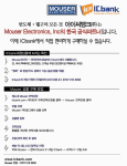
RS232 Connector Details
On the rear panel of the unit, a 9 pin D-type male connector is provided for the
RS232 communication. The DSR and DTR handshake lines are not used. But the
interface cable which connects the COMM INTF on the instrument to the PC COM
port (COM 1 or COM 2) should interconnect the RXD and the TXD line, such that the
RXD input the instrument is the TXD output of the host controller or PC. Swapping is
done internally to avoid confusion in the connection. The connector definition of the
‘COMM INTF’ (as marked on the rear panel) are given below:
PIN NUMBER
DESCRIPTION
PIN 2
Receive Data (RXD)
PIN 3
PIN 5
Transmit Data (TXD)
Ground (GND)
Fig. 6.1
Since the RS232 communication does not use the handshaking the DSR
input of the controller should be tied up to a signal that is always TRUE. However
this implies that your BUS CONTROLLER must always be ready to accept the
data. So the interface cable has to be a customized one. Refer fig 6.1.
23
6.3.3
INSTALLATION OF RS232 CARD
The RS232 Interface (ISO_RS232_CONV-1103 Card) card may come already
installed, if ordered. If this interface is to be installed later, the card can be mounted
on the rear panel of the unit using L-clamp provided on the card itself & following
cards &cables shall be provided along.
Cards:
♦ ISO_RS232_CONV-1103
♦ VSP-FP-DAC-1003
♦
♦
♦
♦
♦
♦
♦
♦
♦
♦
♦
♦
♦
♦
♦
♦
♦
Cables:
3 PIN serial communication (Tx, Rx) data cable (J10) on ISO_RS232_CONV-1103
+10V supply cable to be connected on 3 PIN connector (J3) on ISO_RS232_CONV-1103
Following is the procedure to install the card. :
Release the TOP COVER of the unit by unscrewing 6 screws at the top & 6 screws at
the side panel of the unit.
Remove the TOP COVER (upper plate) of the unit by sliding it out.
You will see a number of cards inside the unit. Please do not touch any of these.
Remove the existing communication card / Connector, which is connected to the slot at
the back of the unit marked as ‘DIGITAL INTF’.
Fit the card “ISO_RS232_CONV-1103” on the rear panel of the unit using L-clamp provided on the card itself.
Check if the link at JP1 is open
Initially disconnect the 26-pin cable from J4 on “VSP-DPM CONT1003” card.
Insert the card “VSP-FP-DAC-1003” onto the “VSP-DPM CONT-1003” such that 16-pin
DIL female (J3) & 26-pin DIL female (J1) on “VSP-FP-DAC-1003” are plugged in 16-pin
DIL male (J7) & 26-pin DIL male (J4) on the “VSP-DPM CONT-1003” card respectively.
Now connect the 26-pin flat cable, which was removed from J4 on “VSP-DPM CONT1003” to the 26-pin DIL male (J2) on “VSP-FP-DAC-1003” card. So now the 26-pin DIL
male (J1) on “VSP-POT-IMON-0703 “is connected to 26-pin DIL male (J2) on “VSP-FPDAC-1003” card.
Do not change the connection between 26-pin DIL male (J2) on “VSP- POT-IMON-0703 “
& 26-pin DIL male (J6) of “VSPDDC-1.2KW-1003D”
Connect 3-pin SIL connector (J3) on “VSP-POT-IMON-0703“ to the 3-pin SIL connector
(J2) on “ISO_RS232_CONV-1103” card, which is connected to the switch on rear panel,
which decides to select either remote or RS 232 interface.
Two connectors are connected to 4-pin SIL connector (J2) on the “VSPDDC-1.2KW1003D” one of which is 4-pin SIL connector (J4) on “VSP-POT-IMON-0703“ & other is 3pin SIL connector (J3) on “ISO_RS232_CONV-1103” card
Using 3-pin SIL connector connect J10 of on the “ISO_RS232_CONV-1103” card with J10
on “VSP-DPM CONT-1003” card, which are the Transmit & receive signals along with
common ground signal.
Verify the signal connections again & select RS232 Interface using slide switch provided
on rear panel.
Turn on the unit & test its functionality. Replace the TOP COVER and close the instrument.
24
6.3.4
RS232 Commands
Following section deals with the commands set for RS232 interface.
It specifies the syntax of each command, which reads the status of power supply or
configures it to the requirements of users.
NOTE: The command uses following notations
<SP> = Indicates Null or space character (20H)
<AARD>
= Indicates Arbitrary ASCII Response Data
<NR.DATA> = Indicates Numeric Data
<EOS>
= Indicates End of string character (ODH)
1.
Command
: READ? <EOS>
Description: Read Output Voltage and Current Query.
Function: This command reads back the output voltage & current of the unit in
<AARD> format. The units for Voltage and Current are VOLTS and AMPS respectively. If the unit is in CV (Constant Voltage) or in CC (Constant Current) mode of
operation, this status is also indicated on console. The entire response is terminated
with <EOS> byte.
For example if the Query sent is
READ? <EOS>
Then the response can be as follows:
+14.99V 00.02A CV<EOS> or +14.00V 10.00A CC<EOS>
2.
Command
: VOLT<SP><NR.DATA><EOS>
Description: Set the Output Voltage for that Channel(s).
Function: This command sets the Output Voltage of the Power Supply output with
the <NR.DATA> given in the command in Volts. The input VOLTAGE data is in Numeric Data format.
For example to set 10.5 Volts then send the command as
VOLT 10.50<EOS>
3.
Command
: CURR<SP><NR.DATA><EOS>
Description: Set the Output Current Limit for that Channel(s).
Function: This command sets the Output Current of the Power Supply output with
the <NR.DATA> given in the command in AMPS. The input CURRENT data is in
Numeric Data format.
For example to set 2.3 Amps send the command as
CURR 02.30<EOS>
25
4.
Command: VOLT: PROT<SP><NR.DATA><EOS>
Description: Set Over Voltage Protection Limit of OUTPUT
Function: This command sets the Over Voltage Protection Limit of the Power Supply
output with the <NR.DATA> given in the command in Volts. The input VOLTAGE data
is in Numeric Data format. Once this OVP limit is set, any time if the actual Output
Voltage of the channel exceeds the OVP limit, the OUTPUT will be ‘TRIPed’. I.e. the
OVP operates to protect the output and the O/P voltage will be made zero and the
OUTPUT ON/OFF relay will be switched OFF.
For example to set OVP of 31.50 V for output, send the command as
VOLT: PROT 31.50<EOS>
5.
Command
: OUTP<SP>ON<EOS>
Description: Turn ON the output of power supply.
Function: This command is used to make the OUTPUT available at the output
terminals.
6.
Command
: OUTP<SP>OFF<EOS>
Description: Turn OFF the output of power supply.
Function: This command is used to switch OFF the output & thus to make the
OUTPUT zero at the output terminals.
7.
Command
: SYST: REM<EOS>
Description: Takes the instrument into Remote Mode of operation
Function: This command will explicitly take the unit to remote mode. All the front
panel controls are disabled.
8.
Command
: SYST: LOC<EOS>
Description: Take the instrument to Local mode of Operation.
Function: This command will take the unit to Local mode of operation & ALL the front
panel controls are enabled.
26
9.
Command
: STAT? <EOS>
Description: Read Status Query.
Function: This command reads the status of various events occurred in the
system. The definition of events is given below
B0:
B1:
B2:
B3:
B4:
B5:
B6:
B7:
Over voltage Trip
Over Temperature Trip
Power On event (Sets when unit is turn ON. The bit gets cleared after the
quarry.)
Internal Failure
Always 1 (THIS STATUS BIT MAY BE CHANGED IN FUTURE)
Always 1 (THIS STATUS BIT MAY BE CHANGED IN FUTURE)
Command Error (Sets if invalid command received by unit. The bit gets
cleared after the quarry.)
Always 0
The response to the quarry is single character followed by EOS.
For example after power On condition the response to the quarry
STAT?
Will be
4<EOS>. If Over voltage trip condition occurs then the response will be
1<EOS>.
6.4
IEEE-488 OPERATION:
The IEEE-488 (GPIB) interface option allows the instrument to connect and
form part of an Automated Test System. The instruments are instructed over a
Parallel Data Bus, so that their facilities can be selected remotely. The ADDRESS
concept, Parallel Data Bus and Handshaking are the main advantages over the
RS23C interface, by which at a time more than one instrument (up to 31 instruments) can be connected on the IEEE-488 bus and only the Addressed instrument
can be made to LISTEN or TALK without losing any data. The communication will
be faster because of parallel data transfer.
The IEEE-488 bus has standard 24 PIN flat cable, in which each line is
dedicated to a special BUS activity. The CONTROLLER can send messages or
receive responses from all or any one instrument by proper BUS activation and
handshaking.
27
6.4.1 IEEE-488 Interface Configuration
The IEEE-488 Interface is a parallel BUS for Communication in the Programmable Instruments. Multiple instruments can be connected on the same BUS and
can be hooked up to a single HOST controller or computer. In order that instruments
from different manufacturers can be built into the same system, it was necessary
that all interfaces be compatible. To ensure this, the interfaces were made to conform to a standard specification as detailed in the publication ANSI/IEEE Std. 4881978 called ‘IEEE Standard Digital Interface for Programmable Instrumentation’ (And
also to ANSI/IEEE std.488.1-1987) and this came to be known as IEEE-488 or GPIB
Interface.
The following list highlights the salient characteristics of the IEEE-488 Interface:
DATA RATE
1 MB/Sec. MAX.
NO. OF DEVICES
31 MAX.
BUS LENGTH
20 Meters. MAX.
DATA LENGTH
8 BITS / 1 BYTE
28
6.4.2 IEEE-488 Connector Details
The instrument provides a standard 24 pin GPIB connector (marked as COMM
INTF on the rear panel of the instrument) to connect it with the standard GPIB (IEEE488) bus. Refer FIG. 6.3 for connector types definition diagram.
Description of the GPIB Signals is given below.
PIN NO.
1
2
3
4
5
6
7
8
9
10
11
12
NAME
DIO 1
DIO 2
DIO 3
DIO 4
EOI
DAV
NRFD
NDAC
IFC
SRQ
ATN
SHIELD
13
14
15
16
17
18
19
20
21
22
23
24
DIO 5
DIO 6
DIO 7
DIO 8
REN
GND 6
GND 7
GND 8
GND 9
GND 10
GND 11
LOGIC
DESCRIPTION
Data Input Output Line 1
Data Input Output Line 2
Data Input Output Line 3
Data Input Output Line 4
End or Identify
Data Valid
Not ready for Data
Not Data Accepted
Interface Clear
Service Request
Attention
Screening on cable (connected to Instrument
Safety Ground).
Data Input Output Line 5
Data Input Output Line 6
Data Input Output Line 7
Data Input Output Line 8
Remote Enable
Gnd wire of twisted pair with DAV.
Gnd wire of twisted pair with NRFD.
Gnd wire of twisted pair with NDAC.
Gnd wire of twisted pair with IFC.
Gnd wire of twisted pair with SRQ.
Gnd wire of twisted pair with ATN.
GND Instrument Logic Ground.
TABLE 6.1
29
6.4.3 IEEE-488 Operational Sequence Guidelines
Most interface communication tasks require a sequence of coded messages to be sent over the interface. It is recommended that a careful study of
the available controller capabilities be made many of them assigning one
programming instruction to these sequences. Different controllers will not
necessarily have identical sequences or program instructions.
The following sequences are recommendations only.
DATA TRANSFER
ATN
DATA
FUNCTION
1
1
UNL
(LAD)
1
(LAD) n
0
(TAD)
Inhibits all current listeners
1Each address sent enables a specific device re
ceives future data bytes
More than one address may be sent if multiple listeners
desired.
The address sent enables a specific device to send data
0
(DAB)
1
UNT
UNL
LAD
TAD
DAB
UNT
=
=
=
=
=
Data bytes sent by currently enabled talker to all currently
enabled listeners.
Disables the talker on receipt of last character.
Unlisten
Listen address of specific device
Talk address of specific device
Data bytes
Untalk
SERIAL POLL
ATN
DATA
FUNCTION
1
1
UNL
SPE
1
(LAD) n
0
(TAD)n
Prevents other devices listening to status sent
Puts interface into serial poll mode during which all
devices send status instead of data when addressed.
More than one address may be sent if multiple listeners
desired.
Enable a specific device to send status.
Within these loop devices should be sequentially enabled.
1
SBN
or SBA
1
1
SPD
UNT
Status byte sent by enabled device. If SBN sent, loop
should be repeated. If SBA sent, the enabled device
is identified as having sent SRQ over the Interface
and will automatically remove it.
Disables Serial Poll mode
Disable Last Talker.
30
UNL
SPE
SPD
SBN
SBA
6.4.4
=
=
=
=
=
Unlisten
Serial Poll Enable
Serial Poll Disable
Status Byte Negative, where BIT 6 = 0 (BIT 7 is the MSB)
Status Byte Affirmative, where BIT 6 = 1 (BIT 7 is the MSB)
Installation procedure for GPIB interface option in the VSP series power
Refer to the general assembly layout of the VSP series power supplies. In the
standard units RS232 interface is provided by default. Accordingly, at the location no.
12 the RS232 interface card (ISO-RS232 CONV-0304A) is installed. Also the control
card required for GPIB option (SBC-IEB-0504A) is not installed at location no. 18. The
connectors required for its control supply are secured on the spacers provided for
mounting.
The GPIB installation kit contains the following cards and the cables.
1)GPIB control card: SBC-IEB-0504A – 1 No.
2)GPIB interface card: INSTR- TO – GPIB – 1188
3)26 pin FRC cables: 2 no.
4)16 in FRC cable: 2 no.
Following procedure should be followed for the GPIB option installation:
1) Remove the top cover of the unit in which the GPIB option needs to be installed by
unscrewing the mounting screws. (3 screws on each side and 6 screws on the top)
Please do not remove the screw provided for the top cover earthing on the rear top of
the cover. Remove the spade connector provided for top cover earth connection, after
removing the cover to take it out.
2) Refer to general assembly drawing for the detailed description of the cards inside the
unit.
3) Remove RS232 interface card (ISO-RS232 CONV-0304A) at the location no.12. (2
screws from the rear panel and one from the top)
4) Remove VSP-DAC-CONV-0604A, at the location no. 20 by removing the ‘L’ type
clamp provided in the new version units or by removing the cable tie in the old version
unit.
5) For serial interface (RS232), the micro-controller on the front panel control board is
served as the main controller accordingly it is flash programmed. For GPIB option, the
SBC – IEB –0504A card has an EPROM with the main program burned in. The controller on the front panel control board is served as slave controller for displaying the
control parameters. Accordingly, it needs to reprogram for the same. Please follow the
procedure for reprogramming.
6) Reprogramming of front panel control PCB for GPIB option:
a) Make sure that the folder named msp_vsp_gpib exists in the pc where the IAR
embedded workbench is installed.
b) Connect the JTAG connector to J1 of VSP-DPM-CONT-1204D (location no. 9).
Please make sure that pin no. 1 of female connector (16 pin) corresponds to
pin no. 1 of male connector (14 pin).
c) Run IAR embedded workbench.
d) Open the project named VSP_INTG from the msp_vsp_gpib folder.
e) Select the correct path for GEN.xcl (d:msp_vsp-gpib\gen.xcl).
31
f) Compile the project.
g) Connect line input to the unit. Keep the front panel output ON/OFF switch in
OFF position. Turn the unit on with the input ‘Line’ switch.
h) Run CSPY to download program in flash memory of the controller.
i)
j)
Press the RESET button in the window and exit from CSPY.
Turn OFF the unit & remove JTAG connector. This will complete the software
installation for GPIB option.
7) Again turn the unit ON & confirm the polarity of the supplies on the supply connector
provided for GPIB option. (At 3 pin connector connected to J7 of SBC-IEB-0504A, Pin
no. 1 is + ve, pin no. 2 is common and pin no. 3 is –Ve supply. The Voltage is approximately 10 Volts. At 4-pin connector connected to J5 of SBC-IEB-0504A, Pin no. 1 is +
ve and pin no. 4 is –Ve supply. The Voltage is approximately 10 Volts. ) Turn The unit
OFF.
8) For the GPIB option, there is provision of the jumper links on the VSP-DPM-CONT1204D for the hardware correction. Remove JP6 near IC U4 (This will disconnect the
+5V supply presently sourced from display board).
9) Remove jumpers JP2, JP3, JP4 & JP5. (This will isolate CV, CC, OVP and OT signals from connector J4)
10) Install jumper JP1 for GPIB mode. (By default, this jumper is open and need to install
in GPIB option).
11) Mount the INSTR-TO-GPIB-1188 pcb on the location 12 with the rear 2 screws.
12) Before mounting the SBC-IEB-0504A pcb make sure that FRC connectors provided
for interconnection are placed according to following table. Also place the insulation
paper below the pcb & route the cables below the pcb.
13)
Sr. No.
01
Cable Type
26 Pin FRC (Long)
Connector No. on
SBC-IEB-0504A
PCB
To
J6
J1 of INSTR-TO-GPIB-1188
02
26 Pin FRC
J8
J1 of VSP-POT-IMON-0604A
(Location no. 19)
03
16 Pin FRC
J2
J7 of VSP-DPM-CONT-1204D
04
16 Pin FRC
J3
J5 of VSP-DPM-CONT-1204D
05
3 Pin SIL
J7
Existing in the unit wired for GPIB
option.
06
4 Pin SIL
J5
Existing in the unit wired for GPIB
option.
14) Please make sure that the pin no. 1 of all the connectors are properly installed to the
pin no 1 of destination connector.
15) Now the unit is set for GPIB option. Turn the unit ON with ‘Line’ switch. Display will
show the blank digits for a while and after a small delay it is ready to work in the
LOCAL mode of operation.
16) Check the GPIB interface with the standard available PCI-GPIB interface software.
Turn the unit OFF.
17)Now reconnect the earth connection to the top cover & reinstall the top cover. This will
complete the installation of GPIB interface.
32
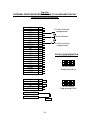
Remove JP2,JP3, JP4 & JP5
From J3 of SBC-IEB
Install JP1
From J2
Remove Jumper Link here.
VSP-DPM-CONT
To J7
To J5
To J1 of VSP-POT-IMON
To J1 of INSTR-TO-GPIB
6.4.5
IEEE-488 Instrument Address Selection
The instrument address is set manually using an eight way miniature
switch near the interface connector on the rear panel. This DIP switch is normally marked with A0 to A7 to identify the proper switch. In our system, we refer
A0 as switch 1 and an A7 as switch 8. The OPEN (OFF) condition of the
switches will simulate logic 1 and CLOSE (ON) condition will simulate logic 0.
These states are marked on the panel as ON (0) and OFF (1).
Five of the switches (A0 to A4) are used to set the address using the
binary code. This enables any address in the range 00 (00 HEX) to 31 (1F
HEX) to be used. E.g. 11010 is address 26 (1A HEX).
The switch no A5 is not used. The remaining two switches (A6, A7) are
used to say whether the installed IEEE-488 Interface card has to be honored or
not. In easy terms, if switches A6 and A7 are CLOSED (ON) simultaneously, the
installed IEEE-488 Interface card is ENABLED. If switches A6 and A7 are not
simultaneously CLOSED (ON), then the IEEE-488 Interface card will be DISABLED even if the address is set properly.
NOTE:
THE CONFIGURATION OF IEEE-488 INTERFACE CARD AND THE ADDRESS
SETTING OF THE INSTRUMENT HAS TO BE DONE BEFORE THE INSTRUMENT
IS SWITCHED ON. AFTER POWER ON, CHANGING OF THE SWITCH SETTINGS
ON THE IEEE-488 INTERFACE CARD WILL NOT HAVE ANY EFFECT ON REMOTE OPERATION OF THE INSTRUMENT.
33
ADDRESS SWITCHES
SWITCHES
A4
0
0
0
0
0
0
0
0
0
0
0
0
0
0
0
0
1
1
1
1
1
1
1
1
1
1
1
1
1
1
1
A3
0
0
0
0
0
0
0
0
1
1
1
1
1
1
1
1
0
0
0
0
0
0
0
0
1
1
1
1
1
1
1
A2
0
0
0
0
1
1
1
1
0
0
0
0
1
1
1
1
0
0
0
0
1
1
1
1
0
0
0
0
1
1
1
A1
0
0
1
1
0
0
1
1
0
0
1
1
0
0
1
1
0
0
1
1
0
0
1
1
0
0
1
1
0
0
1
5-BIT DECIMAL
CODE
A0
0
1
0
1
0
1
0
1
0
1
0
1
0
1
0
1
0
1
0
1
0
1
0
1
0
1
0
1
0
1
0
00
01
02
03
04
05
06
07
08
09
10
11
12
13
14
15
16
17
18
19
20
21
22
23
24
25
26
27
28
29
30
HEX CODE
00
01
02
03
04
05
06
07
08
09
0A
0B
0C
0D
0E
0F
10
11
12
13
14
15
16
17
18
19
1A
1B
1C
1D
1E
TABLE 6.2
The Other three switches (A7 A6 A5) must be kept to 000 (ON, ON, ON).
34
6.4.6
Special Notes For the Controller Software Writer
This section will provide some valuable hints to the controller software program
writer for interfacing this Programmable Unit, through the communication interface.
1).
Normal communication is in ASCII. The unit will accept both the lower case and
upper case characters.
2).
All commands for the units are in the IEEE-488.2 and SCPI format.
3).
All mandatory commands for IEEE-488.2 are implemented in the unit.
4).
Also the command has to be sent with proper terminator (The Program Message Terminator is either = 0AH (NEWLINE) OR EOI message OR both of the
above). Else the command processing will not start.
5).
For the responses of query commands, the Response Message Terminator or
EOS character will be OAH (New Line) character.
6).
For all commands <AARD> means Arbitrary ASCII Response Data and
<NR.DATA> means Numeric Data.
7).
For wrong commands, the command error bit will be set & an error message is
put into Error Queue.
8).
Unit will go to remote mode for all valid commands. Queries will not force the unit
into remote mode.
9).
The GPIB ‘GTL’ command will send the unit into Local mode.
10). IEEE-488 device clear commands ‘SDC’ & ‘DCL’ will generate a communication
soft reset to the unit. Present communication buffer will be flashed out. But, the
unit will maintain the last settings.
11).
When the unit has received MLA (My Listen Address) with REN line true, it will go
to remote mode as per the RL2 function requirements.
12).
The unit provides complete SRQ function. Refer section 5.10 for details. When
the controller polls the SRQ response byte, it is found in case of some controllers that this response byte gets latched in the controllers data in buffer causing
an extra character while reading the next message through GPIB. So, it is advisable to give a dummy listen to the controller GPIB controller chip with sufficient
time-out to flash out such character if pending any.
35
13). Before sending the unit into talk mode it is also advisable to
Flush out the controller’s data-in buffer by giving a dummy read. This is required
because some controller can keep the last data latched into its data-in Buffer.
14). If you send more than one query in a <PROGRAM MESSAGE>, only the LAST
correct query will be processed and response will be given for last query.
15). No response can be read without giving a query. Otherwise the query error bit will
be set & an error message is generated.
6.5
An Introduction to SCPI Language
Standard Commands for Programmable Instruments (SCPI) defines how you
communicate with an instrument from a BUS controller. The SCPI language uses a
hierarchical structure similar to the file systems used by many bus controllers. The
command “TREE” is organized with root-level commands (also called “SUBSYSTEMS”) positioned at the top, with multiple levels below each root level command. You must specify the complete path to execute the individual lower-level
commands.
USING A COLON (:)
When a colon is the first character of a command keyword, it indicates that the
next command mnemonic is a root-level command. When a colon is inserted between two-command mnemonics, the colon moves the path down one level in the
present path (for the specified root-level command) of the command tree. You must
separate the command mnemonics from each other using a colon. You can OMIT
the leading COLON if the command is the first of a new program line.
USING A SEMICOLON (;)
Use a semicolon to separate two commands within the same command
string. The semicolon does not change the present path specified. For example the
following two statements are equivalent.
: SOURce:VOLTage 10.55:SOURce:CURRent 2.50
: SOURce: VOLTage 10.55;CURRent 2.50
USING A COMMA (,)
If a command requires more than one parameter, you must separate the
adjacent parameters using a comma.
36
USING WHITESPACE
You must use Whitespace characters, [tab], or [space] to separate a parameter from a command keyword. Whitespace characters are generally ignored only in
parameter lists.
USING “?” COMMANDS
The BUS controller may send commands at any time, but an SCPI instrument
may only send responses when specifically instructed to do so. Only QUERY com
mands (commands that end with a “?”) will instruct the instrument to send a response
message. Queries return either measured values or internal instrument settings or
some ERROR messages.
CAUTION
IF YOU SEND MORE THAN ONE QUERY COMMAND WITHOUT READING
THE RESPONSE FROM THE EARLIER ONES, AND THEN ATTEMPT TO READ
THE RESPONSE FROM THE LAST QUERY, YOU MAY OR MAY NOT RECEIVE
SOME DATA FROM THE EARLIER RESPONSES. BUT YOU WILL RECEIVE
COMPLETRESPONSE FOR THE LAST QUERY. TO AVOID THIS DO NOT SEND A
NEXTQUERY COMMAND BEFORE READING THE RESPONSE FROM THE FIRST
ONE.
USING “*” COMMANDS
Commands starting with a “*” are called Common Commands (Mandatory
commands for IEEE-488.2). They are required to perform the identical function for all
instruments that are compliant with the IEEE-488.2 Interface Standard. The “*”
Commands are used to control reset, Self-Test and status operation and reporting in
the present instrument.
6.5.1 SCPI Data Types
The SCPI language defines the different data formats for use in program
messages and response messages. Instrument is flexible listeners and can accept
commands and parameters in various formats. However, SCPI instruments are
PRECISE talkers. This means that the SCPI instruments will always respond to a
particular query in a predefined, rigid format.
NUMERIC PARAMETERS:
Commands that require numeric parameters will accept all commonly used
decimal representations of numbers including optional signs, decimal points and
scientificnotation. Special values for numeric parameters like MAXimum, MINimum
and DEFault are also accepted. You can also send engineering unit suffixes (M, k, or
u) with numeric parameters. If only specific numeric values are accepted, the
instrument will automatically round the input numeric parameters.
37
DISCRETE PARAMETERS:
Discrete parameters are used to program settings that have a limited number
of values (like BUS, EXTernal, NORmal, and INVerted). They have a short forms and
a long form just like command keywords. You can mix upper case and lower-case
letters. Query responses will always return the short form in upper-case letters.
BOOLEAN PARAMETERS:
Boolean Parameters represent a single binary condition that is either TRUE or
FALSE. For a false condition the instrument will accept “OFF” or “0”. For a true
condition this instrument will accept “ON” or “1”. When you query a Boolean setting,
the instrument will always return a “0” or “1”.
STRING PARAMETERS:
String Parameters can contain virtually any set of ASCII characters. A STRING
must begin and end with matching quotes, either with a single
Quote or with a double quote. You can include the quote delimiter as part of the
string by typing it twice without any characters in between.
6.5.2
Input Message Terminators
Program Messages sent to an SCPI instrument must terminate with a <
NEWLINE > character. The IEEE-488 EOI (END OR IDENTITY) signal is interpreted
as a < NEWLINE > character and may also be used to terminate a message in
place of the < NEWLINE > character. Many programming languages allow you to
specify a message terminator character or EOI state to be automatically sent with
each BUS transaction. Message termination will always set the current path back to
the root-level.
6.5.3
SCPI Goals
The goal of Standard Commands for Programmable Instruments (SCPI) is to
reduce Automatic Test Equipment (ATE) program development time. SCPI accomplishes this goal by providing a consistent programming environment for instrument
control and data usage. This consistent
Programming environment is achieved by the use of defined program messages, instrument responses and data formats across all SCPI instruments, regardless of manufacturer.
The advantage of SCPI for the ATE system programmer is reducing the time
learning how to program new SCPI instruments after programming their first SCPI
instrument.
By providing a consistent programming environment, replacing one SCPI
instrument with another SCPI instrument in an ATE system will usually require less
effort than with non-SCPI instruments.
38
6.5.4
SCPI Status Model
All SCPI instruments implement status registers in the same way. The status
system records various instrument conditions in three register groups:
The Status Byte register
The Standard Event register and
The Questionable Data register.
The status byte register records high level summary information reported in the
other register groups.
The diagram on the next page illustrates the SCPI status system.
Event Registers:
The standard and the questionable data registers have event registers. An
event register is a read-only register that reports defined conditions within the instrument. Bits in the event registers are latched. Once an event bit is set, subsequent
state changes are ignored. Bits in an event register are automatically cleared by a
query of that register (such as *ESR? or STAT: QUES: EVEN?) or by sending the
*CLS (clear status) command. A reset (*RST) or device clear will not clear bits in
event registers. Querying an event register returns a decimal value, which corresponds, to the binary weighted sum of all bits set in that register.
Enable Registers:
An enable register defines which bits in the corresponding event register are
logically Ored together to form a single summary bit. Enable registers are both
readable and writable. The *CLS (clear status) command does not clear enable
registers but it does clear the bits in the event registers. The STATus:PRESet command will clear the questionable data enable register. Querying an enable register
will not clear it. To enable bits in an enable register, you must write a decimal value,
which corresponds, to the binary weighted sum of bits you wish to enable in a
register.
39
SCPI STATUS SYSTEM
40
The Status Byte Register
The status byte summary register reports conditions from other status
registers.Query data that is waiting in the instrument’s output buffer is immediately reported
through the “message available” bit (bit 4). Bits in the summary registers are not latched.
Clearing an event register will clear the corresponding bits in the status byte summary
register. Reading all messages in the output buffer, including any pending queries will clear
the message available bit.
BIT DEFINITIONS-STATUS BYTE REGISTER
BIT
VALUE
0
1
2
DESCRIPTION
DEFINITION
Not Used
Not Used
Questionable Data
DECIMAL
3
4
Not Used
Message Available
8
16
5
Standard Event
32
6
Request Service
64
7
Not Used
128
1
2
4
Always set to 0.
Always set to 0.
One or more bits are set in the Questionable
Data register (bits must be “enabled” in enable
Register)
Always set to 0.
Data is available in the Instrument’s output
buffer.
One or more bits are Set in the Standard Event
register (bits must be “enabled” in enable regist).
The Instrument is requesting the SERVICE
(Serial Poll).
Always set to 0.
The Status byte summary register is cleared when:
♦ You execute a * CLS (clear status) command.
♦ Querying the standard event and questionable data registers will clear only the respective
bits in the summary register.
The status byte enable register (request service) is cleared when:
*
You turn on the power to the instrument.
*
You execute a *SRE 0 command.
USING *STB? TO READ THE STATUS BYTE
The *STB? (Status byte query) command is similar to a serial poll except it is processed like any other instrument command. The *STB? Command returns the same result
as an IEEE-488 serial poll except that the “request service” bit (bit 6) is not cleared if a serial
poll has occurred. The *STB? Command is not handled automatically by the IEEE-488 bus
interface hardware and the command will be executed only after previous commands have
completed. Polling is not possible using the *STB? Command. Using the *STB? Command
does not clear the status byte summary register.
41
TO INTERRUPT YOUR BUS CONTROLLER USING SRQ
*
*
*
*
*
Send a bus device clear message.
Clear the event registers with the *CLS (clear status) command.
Set the *ESE (standard event register) & *SRE (status byte register) enable
masks.
Send the *OPC? (Operation complete query) command and enter the result to
assure synchronization.
Enable your bus controller’s IEEE-488 SRQ interrupt.
TO DETERMINE WHEN A COMMAND SEQUENCE IS COMPLETED.
*
*
*
*
*
*
Send a device clear message to clear the instrument’s output buffer.
Clear the event registers with the *CLS (clear status) command
Enable “operation complete” using the *ESE 1 command (standard event register)
Send the *OPC? (Operation complete query) command and enter the result to
assure synchronization.
Send your programming command string and place the *OPC
(Operation complete) command as the last command.
Use a serial poll to check to see when bit 5 (standard event) is set in the status
byte summary register. You could also configure the instrument for an SRQ
interrupt by sending *SRE 32 (status byte enable register, bit 5).
HOW TO USE THE MESSAGE AVAILABLE BIT (MAV)
You can use the status byte “message available” bit (bit 4) to determine when
data becomes available to read into your bus controller. The instrument sets bits 4
when the first reading becomes ready (which can be READ?). The instrument subsequently clears bit 4 only after all messages have been read from the output buffer.
The message available (MAV) bit can only indicate when first reading is available
following a READ? Or following a *TST? Query command. This can be helpful because you do not know when the Self-Test will be completed after the *TST? Command is given.
THE STANDARD EVENT REGISTER
The standard event register reports the following types of instrument events:
power-on detected, command syntax errors, command execution errors, self-test or
calibrationerrors, query errors, or when an *OPC command is executed. Any or all of
these conditions can be reported in the standard event summary bit through the
enable register. You must write a decimal value using the *ESE (event status enable)
command to set the enable register mask.
42
Note: An error condition (standard event register bits 2,3,4 or 5) will always record one or
more errors in the instrument’s error queue. Read the error queue using SYSTem: ERRor?
The standard event register is cleared when:
* You send a *CLS (clear status) command.
* You query the event register using the *ESR? (Event status register) command.
The standard event enable register is cleared when:
*
*
You turn on the power to the instrument.
You execute a *ESE 0 command.
BIT DEFINITIONS-STANDARD EVENT REGISTER
BIT
VALUE
0
DESCRIPTION
DEFINITION
Operation Complete
DECIMAL
1
Not Used
2
2
Query Error
4
3
Device Error
8
4
5
6
7
Execution Error
Command Error
Not Used
Power On
16
32
64
128
1
All commands prior to and including an *OPC
command have been executed.
The instrument tried to read the output buffer but
it was empty. Or a new command line was
received before a previous query has been read.
Or, both the input and output buffers are full.
The controller tried to read the O/P buffer of the
instrument without giving the Query first or
wrong Channel list was supplied in query.
A Self-Test, Calibration Or Channel TRIP error
occurred.
An execution error occurred.
A command syntax error has occurred.
Always set to 0.
Power has been turned off and on since the last
time the event register was read or cleared.
THE QUESTIONABLE DATA REGISTER
The Questionable Data Register provides information about the FAULTS on the
different CHANNELS of the Source unit. When a CHANNEL TRIP occurs the reason as to
what caused the TRIP on that CHANNEL could be obtained from this register. The CHANNEL
can have Over Voltage trip or Over Current trip or Over Temperature trip. Any or all of these
conditions can be reported in the questionable data summary bit through the enable register.
You must write a decimal value to enable that particular event using the command STATus:
QUEStionable: ENABle < DATA >
43
BIT DEFINITIONS-QUESTIONABLE DATA REGISTER
BIT
VALUE
0
2
3
5
6
7
8
10
11
13
14
15
DESCRIPTION
DEFINITION
OVP trip
OT trip
OVP trip
OT trip
Not Used
Not Used
OVP trip
OT trip
OVP trip
OT trip
Not Used
Not Used
DECIMAL
1
4
8
32
64
128
256
1024
2048
8192
16384
32768
Channel 1 Over Voltage Trip
Channel 1 Over Temperature Trip
Channel 2 Over Voltage Trip
Channel 2 Over Temperature Trip
Always Set to 0
Always Set to 0
Channel 3 Over Voltage Trip
Channel 3 Over Temperature Trip
Channel 4 Over Voltage Trip
Channel 4 Over Temperature Trip
Always Set to 0
Always Set to 0
The questionable data event register is cleared when:
* You execute a *CLS (clear status) command.
* You query the event register using STATus: QUEStionable: EVENt?
The questionable data enable register is cleared when:
* You turn on the power to the instrument.
* You execute the STATus: PRESet command
* You execute the STATus: QUEStionable: ENABle 0 command.
6.6
COMMAND SUMMARY
This section summarizes the SCPI commands available for this Programmable
Instrument. Refer to the later sections in this chapter for more complete details on each
command.
Throughout this manual, the following conventions are used for SCPI command
syntax. Square brackets ([ ]) indicate optional keywords or parameters. Braces ({})
enclose parameters within a command string. Triangle brackets (< >) indicate that
you must substitute a value for the enclosed parameter.
44
SR NO.
1
2
3
4
5
6
7
8
9
10
11
12
13
IEEE-488.2 COMMON COMMANDS
*CLS
*ESE<SP><NR.DATA>
*ESE?
*ESR?
*IDN?
*OPC
*OPC?
*RST
*SRE<SP><NR. DATA>
*SRE?
*STB?
*TST?
*WAI
SR NO.
1
2
3
4
5
6
7
8
9
10
11
12
13
14
15
16
17
18
STATUS REPORTING COMMANDS
SYSTem: ERRor?
STATus: QUEStionable: EVENt?
STATus: QUEStionable: ENABle?
STATus: QUEStionable: CONDition?
STATus :QUEStionable:ENABle<SP><NR.DATA>
STATus: OPERation: EVENt?
STATus: OPERation: ENABle?
STATus: OPERation: CONDition?
STATus:OPERation:ENABle<SP><NR.DATA>
STATus:PRESet
*CLS
*ESE<SP><NR.DATA>
*ESE?
*ESR?
*OPC
*OPC?
*SRE<SP><NR.DATA>
*SRE?
SR NO.
1
2
3
4
5
6
7
8
SYSTEM RELATED COMMANDS
READ?
[SOURce:] VOLTage<SP><NR.DATA><Channel_list>
[SOURce:] CURRent<SP><NR.DATA> <Channel_list>
[SOURce:] VOLTage:LIMit<SP><NR.DATA><Channel_list>
[SOURce:] VOLTage:PROTection<SP><NR.DATA>
<Channel_list>
OUTPut[:STATe]<SP>ON<Channel_list>
OUTPut[:STATe]<SP>OFF<Channel_list>
45
NOTE:
<SP>
<AARD>
<NR.DATA>
<EOS>
<Channel_list>
6.6.1
= Null or space character (20H)
= Arbitrary ASCII Response Data
= Numeric Data
= End of string character (OAH)
= Channel Number operation.
The format for giving the channel list is
(@1)
: Channel number 1
(@1,2) : Channel nos. 1 & 2.
(@1,2:4)
: Channel numbers 1,2,3,4.
Brackets are compulsory.
SPECIAL NOTES ON THE COMMANDS FOR VSP SERIES:
1).
All commands for the unit are in the IEEE-488.2 and SCPI format.
2).
All mandatory commands for IEEE-488.2 are implemented in unit.
3).
Also the command has to be sent with proper terminator. Else the command
processing will not start.
4).
For the responses of query commands, the Response Message Terminator or
EOS character will be OAH (New Line) character.
5).
For all commands <AARD> means Arbitrary ASCII Response Data and
<NR.DATA> means Numeric Data.
6).
For wrong commands, the command error bit will be set & an error message is
put into Error Queue.
7).
Unit will go to remote mode for all valid commands. Queries will not force the unit
into remote mode.
8).
If you send more than one query in a <PROGRAM MESSAGE>, only the LAST
correct query will be processed and response will be given for last query.
9).
The Channel list in the command is optional for single channel power supply.
10). No response can be read without first giving a query. Otherwise the query
error bit will be set & an error message is generated.
11). The local lockout can be set when the instrument is in remote mode of operation.
12). The address of the IEEE-488 interface is default set to 0.
46
6.7
MANDATORY COMMANDS
This section explains in detail the IEEE-488.2 and SCPI MANDATORY common
commands, which are supported by this Programmable Instrument.
NOTE:
<SP>
<AARD>
<NR.DATA>
<EOS>
<Channel_list>
= Null or space character (20H)
= Arbitrary ASCII Response Data
= Numeric Data
= End of string character (OAH)
= Channel Number operation.
The format for giving the channel list is
(@1)
: Channel number 1
(@1,2) : Channel nos. 1 & 2.
(@1,2:4)
: Channel numbers 1,2,3,4.
Brackets are compulsory.
1.
Command
:
Description :
Function
:
*CLS
Clear Status command
This will clear status Data Structure & forces the Instrument to OCIS and OQIS state.
2.
Command
:
Description :
Function
:
*ESE<SP><NR.DATA>
Standard Event Status Enable command.
This <NR.DATA> is from 0-255 & will set or reset the bits
of Standard Event Status Enable Register.
3.
Command
:
Description :
Function
:
*ESE?
Standard Event Status Enable Query
This query command reads the contents of Stan
dard Event Status Enable register in < NR.DATA>(0255) data format.
4.
Command
:
Description :
Function
:
*ESR?
Standard Event Status Register Query
This query command reads the contents of the Standard Event Status Register in <NR.DATA> Numeric Data
(0-255) format.
47
5.
Command
:
Description :
Function
:
*IDN?
Identification Query
This query command will read back the specific information about device. There are 4 fields in the response separated by commas.
Field 1: Manufacturer (DEL)
Field 2: Model number (XXXXXXX)
Field 3: Serial number (0 if not available)
Field 4: Version number (XX.YY)
6.
Command
:
Description :
Function
:
*OPC
Operation complete command
This command tells the device to generate the operation
complete message in the Standard Event register when
all the pending selected device operations have been completed.
7.
Command
:
Description :
Function
:
*OPC?
Operation Complete Query
When this query is sent if the <NR.DATA> response received is ‘1’, then it implies that the device has completed
all pending operations.
8.
Command
:
Description :
Function
:
*RST
Reset Command
This Reset command performs a Device reset & forces
the device into OCIS state & OQIS state and sets the device specific functions to a known state. (Please refer to
section 5.7.1 for the Details of *RST Conditions.)
9.
Command
:
Description :
Function
:
*SRE<SP><NR.DATA>
Service Request Enable Command.
This command sets the bits in the Service Request Enable Register as per the data sent in the <NR.DATA> (0255) data format.
48
10.
Command
:
Description :
Function
:
11.
Command
:
Description :
:
This query command reads back the contents of the Status Byte Register in the <NR.DATA> Numeric Data format
ranging from 0-255.
Command
:
Description :
Function
:
*TST?
Self-Test Query.
This query command causes an internal Self Test & reports whether the Test was completed successfully (
<NR.DATA> = 0 ) or detected any of the errors in the Self
Test ( <NR.DATA> = non-zero ), which are discussed in
detail under section 5.11 of this chapter.
Function
12.
*SRE?
Service Request Enable Query.
This query command reads back the contents of the Service Request Enable Register in the <NR.DATA> Numeric
data format (0-255).
*STB?
Read Status Byte Query.
NOTE: Before running the Self-Test with the *TST? Command set the OVP and
OCP Limits to maximum. Or else the unit will TRIP.
13.
Command
:
Description :
Function
:
*WAI
Wait to continue command.
This command shall prevent the device from executing
any further commands or readings till the No-operation
pending Flag is set true.
14.
Command
:
Description :
Function
:
SYSTem: ERRor?
System Error condition Query.
This command returns the error number & error description from the error queue of the instrument.
If the ERROR QUEUE is empty, 0,“No error”
will be the response. The error queue can hold up to 6
messages. If the entire buffer is full and an ERROR occurs at this moment then the last message in the Error
Queue will be replaced with -350,”Queue overflow”
When a message is read from the queue using the
SYSTem:ERRor? Query, the first one is cleared and all
the messages are shifted one to the start again.
49
15.
16.
Command
:
Description :
Function
:
STATus:QUEStionable:EVENt?
Status Questionable Event Register Query.
This query command returns the <NR.DATA> format (032767) value of the Questionable Event Register, (16 bit
register) specific to instrument, to give the reason for Error. After this QUERY reads the register, the contents of
the Status Questionable Data Event Register are cleared.
Command
STATus:QUEStionable:ENABle<SP>
<NR.DATA>
Set Enable bits for status Questionable Enable Register.
This command takes <NR.DATA> input & puts the corresponding HEX data to status Questionable Enable Register (to enable the corresponding events in Status Questionable Event Register). Since the enable register is also
a 16-bit register, the <NR.DATA> can be in the 0-32767
range. If the input data is out of range then an “Execution
error” will be generated.
:
Description :
Function
:
17.
Command
:
Description :
Function
:
STATus:QUEStionable:ENABle?
Read Status Questionable Enable Register Query.
This query command reads the contents of the Status
Questionable Enable Register, in the <NR.DATA> (032767) format, whose corresponding HEX value represents the bit pattern of the Register.
18.
Command
:
Description :
Function
:
STATus:QUEStionable:CONDition?
Read Status Questionable condition register query.
This query will give the contents of status questionable condition register in <NR.DATA> (0-32767) format, whose HEX
value represents the Bit pattern of the register. This will always read as ‘0’ (ZERO).
19.
Command
:
Description :
Function
:
STATus:OPERation:EVENt?
Read Status operation Event Register Query.
This query returns the contents of the Status Operation
Event register in <NR.DATA> format (0-32767)
whose 16 Bit HEX value represents the Bit pattern of
register. This will always read as ‘0’ (ZERO).
20.
Command
STATus:OPERation:ENABle<SP>
<NR.DATA>
Set the Enable Bits of status operation Enable Register.
This command takes <NR.DATA> input and puts the
corresponding HEX data to Status Operation Enable
Register (to enable the corresponding events in Status
Operation Event Register). Since the enable register
isalso a 16-bit register, the <NR.DATA> can be in the
Description :
Function
:
:
0- 32767 range. If the input data is out of range then
an “Execution error” will be generated.
50
21.
Command
:
Description :
Function
:
22.
Command
:
STATus:OPERation:CONDition?
Description :
Read Status Operation condition register query.
Function
: This query will give the contents of Status Operation Condition
Register in <NR.DATA> (0-32767) format, whose HEX value
represents the Bit pattern of the register. This will always
read as ‘0’ (ZERO).
23.
Command
:
Description :
Function
6.7.1
:
STATus:OPERation:ENABle?
Read Status Operation Enable Register Query.
This query command reads the contents of the Status Operation Enable Register, in the <NR.DATA> (0-32767) format, whose corresponding HEX value represents the bit pattern of the Register.
STATus:PRESet
Resets the Enable Bits of Status Operation and Questionable Enable Register.
This command puts the data as ‘0’ (ZERO) so that corresponding HEX data (00 Hex) will CLEAR the Status Operation Enable and Status Questionable Enable Registers. (to
disable all the corresponding events in the Status Operation Event Register and Status Questionable Data Event
Register ).
*RST Conditions
The following conditions are defined for the PROGRAMMABLE DC POWER
SUPPLY on receiving the *RST command and execute it.
6.8
1).
The Baud Rate of the instrument for RS232 operation is set to 9600 BAUD,
which is variable through Remote mode commands.
2).
The output Voltage, Current, OVP Limit and OCP Limit for all the Channels are
set to the same values as programmed in the Configuration setup, stored in the
EEPROM installed inside the unit.
3).
The output ON/OFF relays for all the Programmable Channels are switched to
‘OFF’ position.
INSTRUMENT (SYSTEM RELATED) COMMANDS
This section explains in detail the Instrument Specific or the System Related
Commands, which are used to Program different parameters of the system. All
commands, except the last two commands (For selecting the Internal or External
SENSE for the output) are SCPI APPROVED commands. But the last two are SCPI
CONFIRMED commands. For this instrument there is NO command, which are not
part of the SCPI definition.
51
NOTE:
<SP>
<AARD>
<NR.DATA>
<EOS>
<Channel_list>
1.
2.
Command
:
Description :
Function
:
Command
:
Description :
Function
:
= Null or space character (20H)
= Arbitrary ASCII Response Data
= Numeric Data
= End of string character (OAH )
= Channel Number operation.
The format for giving the channel list is
(@1)
: Channel number 1
(@1,2) : Channel nos. 1 & 2.
(@1,2:4) : Channel numbers 1,2,3,4.
Brackets are compulsory.
READ?<Channel_list>
Read Output Voltage and Current Query.
This command reads back the output voltage & current
of the unit in <AARD> format. The units for Voltage and
Current are VOLTS and AMPS respectively. If the specified CHANNEL(S) is in CV (Constant Voltage) mode of
operation, no special indication is given. But if it is in CC
(Constant Current) mode of operation then the word ‘CC‘
is put at the end of the response. The entire response is
terminated with <EOS> byte.
Response is in Arbitrary ASCII Response Data format.
<Channel_list> indicates for which all CHANNELS the
DATA has to be read. The responses of two channels
are separated by the RMUS (Response Message Unit
Separator), which is SEMICOLON (;).
The sequence of the Response for more than one channel is the same as the Sequence of the channel numbers specified in the <Channel_list>. If no such
Channel_list> is provided the READ? query will always
read from channel 1.
For example if the Query sent is
READ?(@2,1)
then the response can be as follows:
+14.99V 00.02A;+00.35V 01.99A CC<EOS>
which indicates that CHANNEL 1 is in CC mode.
[SOURce:]VOLTage<SP><NR.DATA>
<Channel_list>
Set the Output Voltage for that Channel(s).
This command sets the Output Voltage of the Power Supply output with the <NR.DATA> given in the command in
52
Volts. The input VOLTAGE data is in Numeric Data format. The <Channel_list> above, indicates for which all
CHANNELS the DATA has to be SET. The same data will
be set on all the specified CHANNEL(S). If no such
<Channel_list> is provided the SOURce command will
always SET to channel 1.
For example to set 10.5 Volts on Channel 2, send the
command as:
SOURce:VOLTage 10.50(@2)
For example to set 30 Volts on Channels 1&2,send the
command as: VOLTage 3.00 E+1(@1:2)
3.
Command
:
Description :
Function
:
[SOURce:]CURRent<SP><NR.DATA>
<Channel_list>
Set the Output Current Limit for that Channel(s).
This command sets the Output Current of the Power
Supply output with the <NR.DATA> given in the command
in AMPS. The input CURRENT data is in Numeric Data
format. The <Channel_list> above, indicates for which
all CHANNELS the DATA has to be SET. The same data
will be set on all the specified CHANNEL(S). If no such
<Channel_list> is provided the SOURce command will
always SET to channel 1.
For example to set 2.3 Amps on Channels 1&2 send the
command as:
SOURce: CURRent 2.300 E+0(@1,2)
For example to set 1 Amp on Channel 1 only, send the
command as:
CURR 1
For example to set 1.99 Amps on Channel 2, send the
command as:
SOUR:CURR 199 E-2(@2)
4.
Command
:
Description :
Function
:
[SOURce:]VOLTage:LIMit<SP>
<NR.DATA><Channel_list>
Set the Upper Limit of O/P Voltage for that Channel(s).
This command sets the Soft Upper Limit for Output
Voltage of the specified CHANNEL(S) of the Power
Supply output with the <NR.DATA> given in Volts. The
input VOLTAGE data is in Numeric Data format. The
<Channel_list> above,
53
indicates for which all CHANNELS the LIMIT has to be SET. The
same data will be set on all the specified CHANNEL(S). Once
this limit is set, from that point onwards the output voltage can
not be set to higher values than this. If you try to set higher value
using SOURce:VOLTage command, the “ Execution error “ will
be generated. At the same time the LIMITS can not be set to a
value, which is more than the MAXimum ratings of the
CHANNEL(S). Also the read value of Voltage is checked with the
Soft Limit Voltage value all the time and if the reading exceeds
the Channel will be TRIPPed, giving the reason for TRIP as S/W
OVP TRIP.
For example to set Limit of 30.80 Volts on Channel 2, send the
command as :
SOURce:VOLTage:LIMit 30.80(@2)
OR
VOLT:LIM 3.08 E+1(@2)
5.
Command
Description :
Function
:
:
[SOURce:]VOLTage:PROTection<SP>
<NR.DATA><Channel_list>
Set Over Voltage Protection Limit for that Channel(s).
This command sets the Over Voltage Protection Limit for that
CHANNEL of the Power Supply output with the <NR.DATA> given
in the command in Volts. The input VOLTAGE data is in Numeric
Data format. The <Channel_list> above, indicates for which all
CHANNELS the OVP has to be SET. The same data will be set
on all the specified CHANNEL(S). If no such <Channel_list> is
provided the PROTection command will always SET to channel
1 OVP. Once this OVP limit is set on a channel, any time if the
actual Output Voltage of the channel exceeds the OVP limit, the
CHANNEL(S) will be ‘TRIPed’. I.e. the OVP operates to protect
the channel and the O/P voltage will be made zero and the OUTPUT ON/OFF relay will be switched OFF.
For example to set OVP of 31.50 V on Channel 2, send the command as :
SOURce:VOLTage:PROTection 31.50(@2)
54
6.
Command
:
Description :
Function
:
OUTPut[:STATe]<SP>ON <Channel_list>
Set the Output relay to ON state for the specified channels.
This command is used to switch on the output relay & thus to
make the OUTPUT available at the output terminals.
7.
Command
:
Description :
Function
:
OUTPut[:STATe]<SP>OFF<Channel_list>
Set the Output relay to OFF state for the specified channels.
This command is used to switch OFF the output relay & thus to
disconnect the OUTPUT available at the output terminals.
8.
Command
:
Description :
Function
:
SYSTem:REMote
Takes the instrument into Remote Mode of operation
This command will explicitly take the unit to remote mode. All the
front panel controls are disabled. It is advisable to put the unit
into REMOTE mode of operation using this command, before
using the instrument in Remote mode.
9.
Command
:
Description :
Function
:
SYSTem:LOCal
Take the instrument to Local mode of Operation.
This command will take the unit to Local mode of operation &
ALL the front panel controls are enabled.
6.9
IEEE-488 COMPLIANCE INFORMATION
Dedicated Hardware Lines:
ATN
IFC
REN
SRQ
Attention
Interface Clear
Remote Enable
Service Request Interrupt
Universal Commands:
ATN
Addressed Commands:
SDC
END
GTL
Selected Device Clear
End Message
Go to Local
55
DCL Device Clear
Attention
IFC
Interface Clear
LLO Local Lock-Out
IEEE-488 INTERFACE COMPATIBILITY :
Although the IEEE-488 Interface specification is called a standard, variations in
implementation within the specifications are permitted. These variations determine the
capabilities of the particular interface and a list of abbreviations are defined in the Standard Document to indicate to the User which Interface capabilities have been designed
in. The TABLE 6.3 below gives the options, which are implemented in this instrument.
CODE
SH1
AH1
T6
TE0
L4
LE0
SR1
RL1
PP0
DC1
DT0
C0
E1
INTERFACE FUNCTION
Source Handshake Complete Capability
Acceptor Handshake Complete Capability
Talker Function.(Basic Talker, Serial Poll, Unaddressed to Talk if
Addressed to Listen).
No Address Extension Talker Mode
Listener Function.(Basic listener, Unaddressed to listen if Ad
dressed to Talk).
No Address Extension Listener Mode
Service Request Complete Capability
Remote / Local Complete Capability (Including Local Lock Out).
No Parallel Poll Capability.
Device Clear Complete Capability
(Accepts DCL & SDC commands and generates a communica
tion soft reset and flashing out the buffer).
No Device Trigger Capability
No Controller Capability
Tristate driver (Jumper selectable between tristate and open
collector).
TABLE 6.3
6.10
SRQ HANDLING DETAILS
This Programmable Instrument has been configured for SR1 function (Complete SRQ Capability). To make use of this feature you must configure your BUS controller to respond to the IEEE-488 Service Request (SRQ) Interrupt. This unit does not
support Parallel Poll capability.
THE SERVICE REQUEST ENABLE (SRE) REGISTER
The Service Request Enable (SRE) register will enable only those events in
the Status Byte Register to generate an SRQ, when the corresponding bit in the SRE
register is set to ‘1’. Thus by writing the required data in the SRE register using the
command *SRE<SP><NR.DATA>, the reasons to generate an SRQ can be defined.
The following table gives the bit definitions of the Service Request Enable (SRE)
Register.
56
BIT DEFINITIONS-SERVICE REQUEST ENABLE (SRE) REGISTER
BIT
VALUE
0
1
2
DESCRIPTION
DEFINITION
Not Used
Not Used
Questionable Data
1
2
4
3
4
Not Used
Message Available
8
16
5
6
7
DECIMAL
Standard Event
32
Not Used
64
128
Always write with 0.
Always write with 0.
If this bit is set, an SRQ will be raised
when one or more bits are set in the
Questionable Data register (bits must be
“enabled” in enable Register)
Always write with 0.
If this bit is written with ‘1’ then an SRQ is
raised when the data is available in the
Instrument’s output buffer.
If this bit is written with ‘1’ then an SRQ is
raised when one or more bits are Set in
the Standard Event register (bits must be
“enabled” in enable register).
Always write with 0.
Always write with 0.
The Service Request Enable (SRE) register is cleared when:
*
You turn on the power to the instrument.
*
You execute a *SRE 0 command.
ENABLING THE SRQ GENARATION:
First use the Service Request Enable ( SRE ) Register to select which
summary Bits of the Status Byte Register will set the low-level IEEE-488 SRQ
Signal. Now write the correct data in the SRE register, for enabling the SRQ reason
in the Status Byte Register. For this the command *STB<SP><NR.DATA> can be
used.After that the query *SRE? Command will return the same value, which was
sent above. Now enable your BUS controller’s SRQ interrupt.
When the Status Byte Register “ REQUEST SERVICE “ bit (Bit 6) is set, an
IEEE-488 SRQ Interrupt message is automatically sent to the BUS controller. The
BUS controller may then POLL the instruments on the bus to identify which one of
the instruments has raised the SRQ. The controller asks all the instruments on the
BUS to place their SRQ message one by one. The one with Bit 6 SET in its Status
Byte Register has requested the SERVICE. Now controller may take necessary
action to service or cancel the SRQ. Reading the status byte using an IEEE-488
Serial Poll only clears the “REQUEST SERVICE” bit or by reading the Event Register
whose Summary Bit (in the Status Byte) is causing the service request.
57
To read the Status Byte Summary Register, send the IEEE-488 Serial Poll Message. Querying the Summary Register will return a Decimal value, which corresponds,
to the binary - weighted sum of the bits, set in the register. Serial Poll will automatically
clear the “ REQUEST SERVICE “ bit in the Status Byte Summary Register. No other
bits are affected. Performing a Serial Poll will not affect the instrument functioning.
USING SERVICE REQUEST (SRQ) AND SERIAL POLL
For example when the Self-Test is performed on this instrument using the command *TST? (using the IEEE-488 Remote interface ), it takes time for the instrument
to conduct the test and report the results to the BUS controller. The response will be
given at the end of the Self-Test. Here user may have to keep reading from the Output
Buffer of the instrument to know the result. But by using the SRQ function one can do
this task in a better way as explained below. :
1)
Enable your BUS controller’s SRQ interrupt.
2)
Enable the SRQ reason “MAV” (Message Available Bit) in the Status Byte Register by sending the command as *SRE 16.
3)
Send the command *TST? from remote for the Self-Test.
4)
Wait till your BUS Controller detects an SRQ on the bus.
5)
When an SRQ is detected, poll the SRQ from this instrument to read the SRQ
response message as 80 (50 Hex). This means that the RQS bit is set and the
MAV bit is set in the Status Byte Summary Register.
6)
Now read the Output Buffer of the instrument from your BUS controller to get the
Response Message of the Self-Test, which will be a 3 digit decimal number like
620 or 603 and so on.
This unit provides complete SRQ function. When the Controller polls the SRQ
Message, it is found that in case of some Controllers that this Response byte gets
latched in the Controller’s Data-out buffer causing addition of an extra character in the
next message which is read against some query command. So it is advisable to give
a Listen to the Controller Chip with sufficient time-out to flush out such character pending, if any.
6.11
ERROR MESSAGES AND REPORTING
This section explains in short the Error Messages, which are stored in the
ERROR QUEUE. and are reported when read through the SYSTem:ERRor? . The
messages are stored when query command syntax or hardware errors have been
detected. A record of up to 6 errors is stored in the instrument’s error queue. Errors
are retrieved in first-in-first-out (FIFO) order.
58
*
No method is available to read the error queue from the front panel menu.
*
The error queue is cleared when power has been off or after a *CLS (clear status) command has been executed.
*
To read the error queue from the remote interface, send query as:
SYSTem:ERRor?
*
Errors have the following format (the error string may contain up to 40 characters):
-100,“Command error”
ERROR QUEUE:
As the errors and events are detected, they are placed in the queue. This queue
is FIRST IN - FIRST OUT. If the queue overflows, the last error or event in the queue is
replaced with the error
-350,”Queue overflow”
Any time the queue overflows, the least recent errors remain in the queue, and
the most recent error or event is discarded. Reading an error from the head of the queue
removes that error from the queue, and opens a position at the tail of the queue for a
new error, if one is subsequently detected.
When all errors have been read from the queue, further queries for this queue
will return
0,”No error”
till another error is recorded in the error queue.
The error or event queue is cleared when any of the following occur:
*
Upon Power up.
*
Upon receipt of a *CLS command.
*
Upon reading the last item from the error queue.
COMMAND ERRORS
Message:
-100,”Command error”
An invalid command was found in the command string. You may have inserted a
character such as #, $, or % in the command header or within a parameter or you have
sent a command which is not supported by the instrument. This error is given for
syntax errors, missing parameter, wrong header, and numeric data error etc.
59
EXECUTION ERRORS
Message:
-200,”Execution error”
A valid command could not be executed because of the unrecoverable TRIP
condition in the related channel(s) or the numeric data given in the command exceeds
the maximum allowed hard limits or the Soft Upper Limits which were set by the Limit
commands. In such cases the instrument generates the Execution error.
DEVICE-SPECIFIC ERRORS
Message:
-300,”Device-specific error”
A Device specific failure has occurred or some fault is detected on any one or
more channels of the instrument. When the CHANNEL is ‘Tripped because of the Over
Voltage Protection, Over Current Protection or Over Temperature Protection, this error
is generated. To read the exact cause of the TRIP on that channel the Status Questionable Data Event Register contents have to be read.
Message:
-330,”Self-test failed”
The instruments complete self-test failed from the remote interface (*TST? command). The result of the self-test is separately reported in the response of the *TST?
query command. The decimal number, which is in response to the above query, indicates what exactly has failed in the Self-test. Refer to next page for more details.
QUERY ERRORS
Message:
-400,”Query error”
A Query error is reported when the controller tries to read the instrument’s OUTPUT BUFFER without first, sending the query. For every response to be received, a
query command has to be sent first. Also in the READ? query, if the <Channel_list>
does not contain any valid CHANNEL number then also the Query error is recorded.
60
Fig 4.1a
REMOTE VOLTAGE AND CURRENT PROGRAMMING AND MONITORING
Factory Set for 0 to 5 Volts for full scale output programming and monitoring
NC
NC
VPROGI
VPIN
VPROGR
AGND3
NC
NC
IPIN
IPROGI
IPROGR
NC
NC
NC
+12V
AGND3
1
2
3
4
5
6
7
8
9
10
11
12
13
14
15
16
REMOTE ON/OFF 17
AMX
18
VMX
19
AGND3
20
NC
21
VPSET
22
VMSET
23
IPSET
24
IMSET
25
External Voltage Control
Input +
Control Common
External Voltage Control
Input +
SWITCH CONFIGURATION
(ON REAR PANEL)
12345678
O
N
for Analoge Voltage
Programming 0-5V
12345678
+S
+
-S
NC
CS BUS
O
N
1
2
3
4
5
6
for Analoge Voltage
Programming 0-10V
Output +VE
Output -VE
LOAD
61
Fig 4.1b
EXTERNAL RESISTANCE PROGRAMMING 0 TO 4.85KOHMS FOR FULL
SCALE VOLTAGE & CURRENT
NC
NC
VPROGI
VPIN
VPROGR
AGND3
NC
NC
IPIN
IPROGI
IPROGR
NC
NC
NC
+12V
AGND3
1
2
3
4
5
6
7
8
9
10
11
12
13
14
15
16
REMOTE ON/OFF 17
AMX
18
VMX
19
AGND3
20
NC
21
VPSET
22
VMSET
23
IPSET
24
IMSET
25
+S
+
-S
NC
CS BUS
Ext. Resistance for
voltage control
Control Common
Ext. Resistance for
voltage control
SWITCH CONFIGURATION
(ON REAR PANEL)
12345678
O
N
for Resistance
Programming 0-5V
1
2
3
4
5
6
12345678
O
N
for Resistance
Programming 0-10V
Output +VE
Output -VE
LOAD
62
Section 7
Customer support
B&K Precision offers courteous, professional technical support before and after the sale of their
test instruments. The following services are typical of those available from our toll-free telephone number.
1-800-462-9832
l
Technical advice on the use of your instrument.
l
Technical advice on special applications of your instrument.
l
Technical advice on selecting the test instrument for a given task.
l
Information on optional accessories for your instrument.
l
Information on instrument repair and re-calibration services.
l
Replacement parts ordering.
l
Availability on service publications.
l
Information on other B&K Precision instruments.
l
Information on other B&K Precision Catalog.
The name of your nearest B&K Precision Distributor.
Call toll free 800-462-9832
Monday through Thursday 8:00 A.M. to 5:00 P.M.
Friday 8:00 A.M. to 12:00 P.M.
Pacific Standard Time
(Pacific Daylight Time Summer)
63
Section8
Warranty information
Limited One-Year Warranty
B&K Precision warrants to the original purchaser that its products and the component parts
thereof, will be free from defects in workmanship and materials for a period of one year from
date of purchase from an authorized B&K Precision distributor.
B&K Precision will, without charge, repair or replace, at its option, defective product or component parts. Returned product must be accompanied by proof of the purchase date in the
form of a sales receipt.
To obtain warranty coverage in the U.S.A., this product must be registered by completing the
warranty registration form on www.bkprecision.com within fifteen (15) days of purchase.
Exclusions: This warranty does not apply in the event of misuse or abuse of the
product or as a result of unauthorized alterations or repairs. The warranty is void if
the serial number is altered, defaced or removed.
B&K Precision shall not be liable for any consequential damages, including without limitation
damages resulting from loss of use. Some states do not allow limitations of incidental or
consequential damages. So the above limitation or exclusion may not apply to you.
This warranty gives you specific rights and you may have other rights, which vary from stateto-state.
B&K Precision
22820 Savi Ranch Parkway
Yorba Linda, CA 92887
www.bkprecision.com
714-921-9095
64
Section9
Service Information
Warranty Service: Please go to our website, www.bkpreicsion.com & click on the service/
repair button to obtain an RMA #. Return the product in the original packaging with proof of
purchase to the address below. Clearly state in writing the performance problem and return
any leads, probes, connectors and accessories that you are using with the device.
Non-Warranty Service: Please go to our website, www.bkpreicsion.com & click on the
service/repair button to obtain an RMA #. Return the product in the original packaging to the
address below. Clearly state in writing the performance problem and return any leads,
probes, connectors and accessories that you are using with the device. Customers not on
open account must include payment in the form of a money order or credit card. For the most
current repair charges please visit www.bkprecision.com and click on “service/repair”.
Return all merchandise to B&K Precision Corp. with pre-paid shipping. The flat-rate repair
charge for Non-Warranty Service does not include return shipping. Return shipping to locations in North American is included for Warranty Service. For overnight shipments and nonNorth American shipping fees please contact B&K Precision Corp.
B&K Precision Corp.
22820 Savi Ranch Parkway
Yorba Linda, CA 92887
www.bkprecision.com
714-921-9095
Include with the returned instrument your complete return shipping address, contact
name, phone number and description of problem.
65
PN: 481-529-9-001
Printed in India
Ó2004 B&K Precision Corp.
22820 Savi Ranch Parkway
Yorba Linda, CA 92887
USA
TEL: 714-921-9095
FAX: 714-921-6422
www.bkprecision.com