1
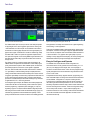
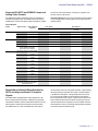
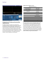
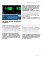
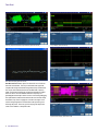
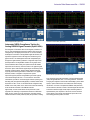
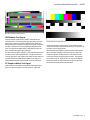
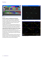
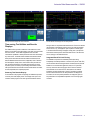
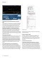
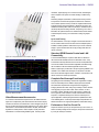
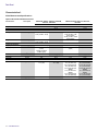
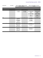
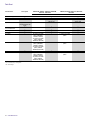
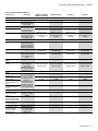
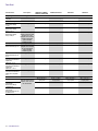
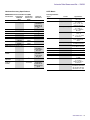
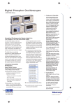
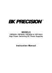
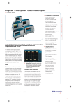
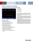
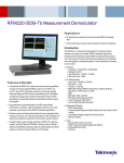
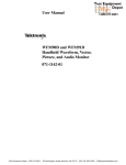
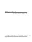
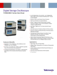
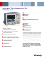
Automated Video Measurement Set
VM6000 Data Sheet
Complete 1 GHz Bandwidth, 4-channel DPO Functionality
Large 12.1 in. XGA Touch Screen Display
GPIB Remote Control
LAN Connectivity
CD-R/W Drive (DVD Read-only)
Pinpoint™ Triggering
Technology-specific Software Options for Jitter and Timing
Measurements, Power Measurements, Serial Data, Ethernet, and USB
2.0 Compliance Testing
Applications
Design Validation
Standards Compliance Testing
Quality Control
Features & Benefits
Automates Test of Consumer HDTV Video Devices
Installation and Troubleshooting
Automated Manufacturing Test
Off-air Video Systems Test
Automates VESA Compliance Test for PC Graphics Devices
Automates Testing of Multimedia PC
Fast, Accurate, and Reliable Video Measurements
Comprehensive Component Analog Video Signal Analysis
SDTV, HDTV, and RGBHV Component Analog Format Support
Picture, Vector, and Waveform Displays
Companion Test Signal Packages
Time-saving Test Utilities
Pass/Fail Limit Testing
Automatic Report Generator
Video Measurement Accessories
The VM6000 automates video testing of consumer HDTV and PC graphics
devices such as digital set-top boxes, multimedia PCs, graphics cards, and
video semiconductors. It addresses the needs of engineers developing and
deploying the next generation of video devices for the digitally connected
home. Unrivalled performance in terms of speed, accuracy, and reliability
has made the VM6000 the choice of industry leaders for design validation,
quality control, and ATE applications.
Unlike conventional instruments, the VM6000 integrates acquisition
hardware, optimized video measurement algorithms, test signal files, and
accessories into a cohesive test system solution. Product verification
activities that previously took hours or days to complete can now be
completed in seconds or minutes. Offering near plug-and-play video
measurement capability, even unskilled operators can reliably assess
video output signal quality. The conformance of signals to specifications
is reported with obvious pass or fail results, with signal distortions clearly
identified for further analysis.
Data Sheet
Summary Pass/Fail Test Results Display.
Signal Format Configuration Menu (Option SD and HD).
The VM6000 stands alone as the only automatic video analyzer capable
of supporting SD, HDTV, and PC graphics signal formats. Offering a full
1 GHz bandwidth, and 5 GS/s sample rate, the VM6000 is well suited to
the demands of measuring high-resolution HDTV and high-frequency PC
graphics video signals. Traditional DTV formats from 480i through 1080p
and either RGB or YPbPr color space are supported in Options SD and
HD. Option VGA supports common analog RGBHV signal resolutions from
640×480p though 2048×1536p, and pervasive refresh rates from 60 Hz
through 120 Hz.
easily replicated, and readily communicated across a global engineering,
manufacturing, or sales organization.
The ultimate solution for component analog video signal analysis, the
VM6000 delivers comprehensive characterization of video fidelity, signal
quality, and standards compliance. With available options, the instrument
automatically assesses conformance of video signals to applicable
EIA-770.x, SMPTE-274M, 296M, and VESA VSIS standards. Traditional
“TV” signal fidelity is evaluated utilizing industry-accepted parameters,
making 150 individual measurements automatically in less than 20 seconds.
PC graphics signal fidelity is assessed using comprehensive RGB video and
HV Sync measurement parameters made in accordance with VSIS test
procedures. Preloaded reference and limit files enable go/no-go evaluation
to applicable DMT, CVT, or GTF timing standards.
As an integrated signal analyzer, the VM6000 can be reliably deployed as
a stand-alone QA station in manufacturing. Unlike modular test systems,
extensive programming, complicated system debugging, or costly test
engineering support is not required with the VM6000. Integrated pass/fail
limit testing and documentation utilities link distributed design, supply, and
manufacturing organizations with standardized test capability. Product
quality is enhanced because accurate test results can be reliably generated,
2
www.tektronix.com
These unique capabilities enable in-depth signal analysis, speed product
development, and ensure new designs comply with applicable standards.
Fast, accurate, and objective video measurements enable manufacturers
to ensure that HDTV or PC graphics video signal quality is up to the
challenge of today’s high-performance displays, as well as providing clear
differentiation between input signal and display device impairments.
Easy to Configure and Operate
The VM6000 offers intuitive Windows-based configuration and
measurement menus for easy operation and minimal training. A 12.1 in.
(307 mm) color display provides a bright, clear, and crisp display of
waveforms and measurement results. Users can easily navigate through
logically arranged menus and make selections using radio buttons with a
mouse or touch screen.
Complicated instrument setups, algorithm selection, programming, and
other undesirable aspects of making video measurements are eliminated
with the VM6000. Configuration is as simple as selecting the Auto
Format function or individually selecting the video format manually and
then selecting the measurement parameters from an on-screen menu,
eliminating complicated instrument setups, tedious manual measurements,
and time-consuming results correlation. These test configuration settings
can be readily saved, recalled, or copied, further simplifying test of
multiformat video devices. Users wanting to make manual measurements
can exit the automated measurement application and then access a
full-featured oscilloscope.
Automated Video Measurement Set — VM6000
Supports SD, HDTV, and RGBHV Component
Analog Video Formats
set-top boxes, video semiconductors, DVD players, PC graphics cards,
and other consumer video devices.
The VM6000 can be flexibly configured to support any combination of
component analog SDTV, HDTV, and RGBHV video formats with the
available options. Broad format support enables automated test of digital
User-defined Format allows users to test nonstandard formats by entering
custom timing parameters, allowing support of unique formats and future
undefined formats.
Format Support
Option
SD
HD
VGA
Signal Format
Vertical Refresh
Frequency
480i
59.94/60 Hz
576i
50 Hz
480p
59.94/60 Hz
576p
50 Hz
720p
30/50/59.94/60 Hz
1080i
50/59.94/60 Hz
1080p
24/50/59.94/60 Hz
Other nonstandard HD formats supported
by User-defined Format menu.
User-defined Format supports
nonstandard SD formats, if SD is enabled.
640×480p
60, 72, 75, 85, 100,
120 Hz
800×600p
60, 72, 75, 85, 100,
120 Hz
1024×768p
60, 72, 75, 85, 100,
120 Hz
1280×1024p
60, 70, 75, 85, 100,
120 Hz
1600×1024p
60, 70, 75, 76, 85,
100 Hz
1920×1080p
50, 60, 75, 85,
100 Hz
1920×1200p
60, 75, 76, 85,
100 Hz
1920×1440p
60, 75, 85 Hz
2048×1536p
60, 75, 85 Hz
2048×2048p
60 Hz
Other progressive RGBHV formats
and vertical frequencies supported by
User-defined Format.
RGB
Color Space
YPbPr
Sync Options
Y/G
Composite Sync
on CH4
Separate H&V
X
X
X
X
X
X
X
X
X
X
X
X
X
X
X
X
X
X
X
X
X
X
X
X
X
X
X
X
X
X
X
X
X
X
X
X
X
X
X
X
X
X
X
X
X
X
X
X
X
X
X
X
X
X
X
X
X
X
X
X
X
X
X
X
X
X
X
X
X
X
X
Note: Sync combiner (012-1664-xx) supports “Separate H&V” operation.
Bandwidth and Sample Rates Suitable for
HDTV and High-resolution PC Graphics
Signals
The VM6000 utilizes a digital phosphor oscilloscope platform as the
basis for signal acquisition and analysis. Utilizing proven, high-speed
measurement architecture, Tektronix surpasses the limitations of current
video analyzers to address the evolving needs of the video industry.
The VM6000 offers over 1 GHz of bandwidth and 5 GS/s maximum
real-time sample rates for all 4 measurement channels – easily assessing
the frequency response of 60 MHz HDTV signals or transient response
of 350 MHz PCF VESA signals. The high sample rates and low noise
floor of the instrument enable noise measurement accuracy that was
previously impossible on HDTV signals. A typical rise time of 225 ps and
superior time-base performance are sufficient to make critical sync and
rise-time measurements as required by EIA-770 and SMPTE 274 M and
VESA. Standard 10 M (4 CH) record length and high sample rates deliver
measurement results with minimal time lag.
www.tektronix.com
3
Data Sheet
VM6000 Automated Measurements
Measurement Parameters
TV Signals
Options SD and HD
PC Graphics Signals
Option VGA
Color Bars
Levels (1-8 Pedestals)
HV Sync
H Sync Jitter
Color Bars
Luma Levels*1
HV Timing*1
HV Sync*1
H Sync Jitter*1
Noise Injection Ratio*1
Integral and Differential Linearity,
Monotonicity*1
Channel-Channel Mismatch
Channel-Channel Skew*1
Video Transient Response
—
—
Noise
Nonlinearity
Interchannel Timing
Transient Response, K2T
Multiburst
Frequency Response
—
H Sync Measurement Results (Option VGA)
Comprehensive Component Analog Video
Signal Analysis
The VM6000 incorporates an extensive set of automated video
measurements that deliver comprehensive characterization of the fidelity
and conformance of component analog signals. Approximately 150
individual measurements completely characterize video signal amplitudes,
timing, and noise distortions into parameter categories that are easily
understood, facilitating troubleshooting and design optimization. Enabled
by such broad and thorough signal analysis, the VM6000 is able to identify
relevant video signal impairments, verify compliance with applicable
standards, and ensure operability with connected displays.
4
www.tektronix.com
Spatial Distortion
Resolution*1
—
*1 VESA parameters.
Measurement parameters have been appropriately selected for testing
TV signals (Options SD and HD) and PC graphics signals (Option
VGA). These parameters vary by application because of differences
in hardware technology, signal attributes, applicable standards, and
historical test methodology. TV test measurements are based on the
de facto industry standard VM700T and have been adapted to assess
distortions unique to digital devices and HDTV signals. The PC graphics
measurement set delivers fully automated VESA compliance testing and
video measurements, as well as reporting other parameters commonly
utilized to characterize PC graphics device performance.
Automated Video Measurement Set — VM6000
Auto Range – The Auto Range feature enhances accuracy and enables
Multiburst Measurement Results Display (Option SD and HD).
Fast, Accurate, and Reliable Automated Video
Measurements
The VM6000 is differentiated from conventional oscilloscopes, waveform
monitors, or modular instruments by its automated video measurements.
Automated measurements deliver benefits in terms of speed, accuracy, and
repeatability with ease of use that almost obsoletes manual approaches,
and even user-developed programs. Automating signal configuration,
signal acquisition, and data analysis enables robust and reliable operation,
impervious to signal variations. The VM6000 applies optimized video
measurement algorithms and extended data processing to deliver accuracy
and reliability that outperforms even the most skilled expert user.
Auto Format Detect – Simplifies operation by automatically detecting
the format applied to the instrument. Allows multiple formats to be tested
automatically in sequence without the need for user intervention.
Auto Configuration – By selecting the applicable format and desired
measurements from the configuration menu, the VM6000 automatically
configures gain, offset, and time scale based on the nominal signal values
expected. Variations from nominal values are accommodated with Auto
Range capabilities.
automated measurement of signals that vary from nominal levels. This
feature automatically optimizes gain and offset based on the signal
conditions when they deviate from nominal, enabling the instrument to
consistently present the best results possible.
Automatic Special Position – The VM6000's automatic special position
function ensures that automated measurements are robust to temporal
signal distortions, alternate test signals, and alternate output display modes.
Always active, this feature identifies appropriate test signal events and
sets measurement cursor locations optimally to ensure consistent and
meaningful test results. Measurement location selections made by the
VM6000 can be analyzed or documented with the selectable feature
included in the report generator.
Auto Mode – Auto mode enables users to instruct the instrument to make
one, selected, or all automated video measurements with a single a run
command. While functioning in Auto mode, the instrument automatically
selects the appropriate test signal line, utilizes preset measurement
configurations and averaging selected by the user, and completes each
measurement. Auto mode also includes multiline measurements capability,
enabling users to measure selected parameters on many or all lines in a
frame with a single run command.
Measurement Cursors (Special Position) – Options SD and HD address
requirement for custom signal analysis by enabling users to input
customized measurement locations for the Frequency Response,
Levels, and Noise measurement parameters. For frequency response
measurements, users can select either timing-location input or frequency
input to make response measurements anywhere within the supported
video bandwidth utilizing a standard sweep signal. Input locations can
be further toggled within YPbPr signals to accommodate either 4:2:2 or
4:4:4 video. This enables detailed analysis of roll-off, frequency distortion,
identification of spurs, and aliasing anywhere across the useful frequency
spectrum. Cursors for the Levels parameter enable flexible, automated
measurement of 3 channel levels for 1-8 individual pedestals on a line, such
as can be found with ARIB signals, MacBeth Charts, or other noncolor bar
signals. Noise special position cursors allow temporal windowing for noise
measurements, enabling noise measurements on signals such as color
bars, staircases, or camera test charts.
www.tektronix.com
5
Data Sheet
Frequency Response Measurement Input Selections (Option SD and HD).
Noise Spectrum Display (Option SD and HD).
V Sync Display (Option SD and HD).
H Sync Jitter and Wander Display (Option SD and HD).
New Measurements on V3.X – Options for SD and HD on V3.X offer the
three new measurements. The V Sync measurement will support the
complete video timing measurement along with the H Sync measurement.
The H Sync Jitter measurement measures the RMS Jitter, Frequency
Offset, and Frequency Drift Rate for wander measurements that support
IEEE 1521-2003. The user-definable demarcation frequency and
probability/jitter readout help to search for the root cause during debugging.
The spatial distortion measurement measures the size of the video image
and detects if any offset or cropping has occurred to the image. This is
useful for design engineers to ensure that their video processing is not
deforming the picture. This is also good for verifying video aspect ratio
mixes such as letterbox or side-panel modes.
Spatial Distortion Display (Option SD and HD).
6
www.tektronix.com
Automated Video Measurement Set — VM6000
Format Configuration Menu (Option VGA).
Measurement Selection Menu (Option VGA).
Automated VESA Compliance Testing for
Analog RGBHV Signal Formats (Option VGA)
The emergence of IP broadcast video and convergence of traditional “TV”
and “PC” video entertainment devices have resulted in PCs evolving into
media gateways to the digitally connected home. As a result, assessing
the fidelity and conformance of analog RGBHV signals has become more
important to engineers involved in the design and manufacturing of PC
graphics devices. This challenge has been further complicated by the
emergence of digital interfaces, proliferation of supported output modes,
and the persistence of analog RGBHV interfaces on PC graphics cards.
Tektronix addresses these industry test requirements with the VM6000
Option VGA, the first and only “VM” class solution for PC graphics signals
and devices. Option VGA automates signal analysis and mandatory VESA
standards compliance testing, speeding design validation testing that
is typically performed during the release or modification of PC graphics
hardware, software, or integration of complete video systems.
Option VGA supports pervasive analog RGBHV signal formats typically
communicated through VGA, DVI-I, or DVI-A interfaces. Automated
measurement is possible for 10 standard signal resolutions spanning from
640×480p (VGA) through 2048×2048p (QXGA), at selected vertical refresh
frequencies from 60 to 120 Hz. A user-defined format configuration utility
enables users to easily create, edit, or recall custom modes and seamlessly
access the full test automation of the VM6000 instrument.
Approximately 150 video measurements can be performed for each
supported mode, delivering a comprehensive assessment of RGB video
fidelity, HV Sync quality, and format conformance. Parameters and test
methods are based on industry standard (VESA) test procedures, enabling
RGB Transient Response Measurement Results (Option VGA).
easy comparison against the requirements of the Video Signal Standard
(VSIS) and applicable DMT, GTF, or CVT timing standards. Convenient
averaging and configuration controls deliver the flexibility to perform either
speedy or precise measurements in accordance with VESA sampling
requirements. A full suite of comprehensive RGBHV video parameters
can be measured in less than 5 minutes. Preloaded signal reference data
and tolerance limit files simplify results analysis, eliminating laborious
spreadsheet entry and computation. Test results, and even waveform
screen captures can be quickly documented with reports that can be
automatically generated, printed, and saved.
www.tektronix.com
7
Data Sheet
An innovative set of PC graphics matrix test signals have been created to
enable comprehensive signal characterization for the full range of supported
formats. These signals, working in conjunction with a remote controlled
measurement interface unit, enable fully automated testing with a single run
command. The included measurement interface unit provides connectivity,
signal termination, automated switching, and variable loads for sync voltage
tests. This approach eliminates the need for expensive FET probes, and
delivers optimized accuracy for both DC amplitude and high-frequency
timing measurements.
All the necessary elements for compliance or QC testing are integrated into
a cohesive solution that delivers easily understood pass or fail test results.
Comprehensive parametric signal analysis isolates product performance
deficiencies, enables design optimization, and ensures interoperability of
connected display devices. With Option VGA, even unskilled operators can
make reliable and repeatable assessments of VESA standards compliance.
Extensive video knowledge, oscilloscope skills, complicated programming,
or system integration skills are no longer required to assess analog RGBHV
signal integrity.
signals may contain artifacts that detract from measuring the analog signal
fidelity, the matrix test signal is also provided in MPEG-2/H.264 encoded
Elementary and ATSC Transport Streams. To ensure the encoded signal
is accurate, Tektronix has prequalified the matrix test signal for each native
video format.
Option SS Signal Sources Package (020-2769-xx):
File and Signal Formats of Test Signal Packages
Parts Number
020-2770-xx
020-2771-xx*2
020-2772-xx
020-2773-xx*3
020-2774-xx*4, 5, 6
Description
Formats
Signal Sources DVD
Standard Definition
Elementary Streams
Advanced Definition
Elementary Streams
ATSC Transport Streams
480i, 576i
480i, 480p, 576i, 576p
Baseband Test Signals
020-2775-xx*7
PC Bitmap Graphics
020-2776-xx*8
H.264 SD and HD
Streams
Companion Test Signal Packages
Option SS includes a specific companion test signal package to speed
and simplify testing of supported signal formats. This package has been
developed to enable comprehensive parametric analysis of signal fidelity
without the inconvenience of switching test signals. The test signal package
eliminates potential video measurement set operability issues and minimize
uncertainties regarding the quality of the input signal
Because DTV has resulted in a proliferation in video source content and
signal formats, test signals are provided in a variety of pervasive formats to
enable easy generation and extended format testing. Since encoded test
8
www.tektronix.com
720P, 1080i, 1080p
480i, 480p, 720P, 1080i,
1080p
525i, 525p, 625i, 625p,
720p, 1080i, 1080p,
620×480, 800×600,
1024×768, 1280×1024,
1600×1024, 1600×1200,
1920×1080, 1920×1200,
1920×1440, 2048×1536,
2048×2048
480i, 480p, 576i, 576p,
720p, 1080i, 1080p
*2 480i, 480p ES Stream provided by 704×480, 720×480 resolution.
*3 ATSC Transport Stream provided for 480i, 480p, 720p/30, 720p/60, 1080i/60, 1080p/24, and 1080p/59.94
formats.
*4 Requires TG700 and appropriate module (AVG7, AWVG7, DVG7, and/or HDVG7).
*5 SDI signal generation not supported for 525P, 576p format.
*6 TG700 DNL files not provided for 1080p/50 and 1080p/60 formats.
*7 Includes PC Matrix and Full Field VESA signals.
*8 Main profile / Level 3 for 480i, 580p, 576i, and 576P. Main profile / Level 4 for 720P, 1080i, and 1080P.
Automated Video Measurement Set — VM6000
HDTV Matrix Test Signal in 16×9 Aspect Ratio.
HDTV Matrix Test Signal
A specific matrix test signal has been created to enable efficient and
comprehensive test of component analog video signal fidelity. The matrix
signal includes a range of test signals on different lines to enable video
testing without the inconvenience of switching full field signals, and contents
have been customized to exercise the full bandwidth capability of each
format. One signal can be flexibly utilized for both RGB and YPbPr color
spaces, thereby minimizing test signal proliferation.
The HDTV matrix test signal is supplied in a variety of file and signal formats
to enable convenient and comprehensive test of set-top boxes and other
consumer video devices. High-quality encoded ATSC Transport Stream and
compressed Elementary Stream files are supplied for easy playout on a
Tektronix MPEG player such as the RTX100B, RTX130B, or MTX100B.
PC Graphics Matrix Test Signal
PC Graphics Matrix Test Signal (Option VGA).
includes test signal files for these patterns, in both full field and matrix
forms for the full range of supported image resolutions. Test signal files are
provided in .bmp and .png file formats.
VESA compliance and certification testing requires that several different
types of test signals be applied to the device under test. Option VGA
includes test signal files for these patterns, in both full field and matrix
forms for the full range of supported image resolutions. Test signal files
are provided in .bmp and .png file formats. The .png files are beneficial
because they enable HV timing measurements to be made without the
border artifacts potentially introduced by bitmap files.
VESA compliance and certification testing requires that several different
types of test signals be applied to the device under test. Option VGA
www.tektronix.com
9
Data Sheet
Picture Mode.
Picture, Vector, and Waveform Displays
Picture and Vector displays can be initiated with a single button press
and deliver “at a glance” confidence checking that simplifies signal
identification, troubleshooting, and color conversion accuracy. Waveforms
are simultaneously displayed with parametric test results to enable
visualization of signal impairments.
Vector Display.
By selecting Picture mode, a full-color picture display is rendered on the
screen from the connected subsampled and down-converted signals to the
available picture area and resolution. Pictures appear in an appropriate
16×9 or 4×3 aspect ratio by default; however users can resize, move, or
minimize the window as needed. Picture mode incorporates a user-enabled
bright line select feature to facilitate test configuration. Live or full motion
video signals can also be viewed at vertical refresh rates of 1-2 fps.
The Vector display, available with Option SD and HD, displays the waveform
with targets for 75% or 100% color bars and accommodates either 601 or
709 colorimetry targets. Graticule targets and color space can be selected
automatically or manually.
Waveforms for all channels are simultaneously viewable in different colors,
and displays can be zoomed both vertically and temporally for detailed
examination and analysis. Users can selectively expand the waveform to
the full display size by minimizing the measurement application.
10
www.tektronix.com
Full-screen Waveform Display.
Automated Video Measurement Set — VM6000
Summary Test Results Display with Pass/Fail Indication.
Time-saving Test Utilities and Results
Displays
The VM6000 offers a powerful combination of test utilities and custom
displays to make HDTV video testing faster, more robust, more convenient,
and more accurate. These utilities supplement basic automated
measurement capabilities to deliver performance and value unmatched by
any other solution. Combined with the extended documentation utilities,
these powerful automated measurement utilities and features ensure
that the VM6000 meets the demands of all application areas. Research
and Development, Quality Control, and Production Test personnel can
tailor the instrument settings to meet their particular needs for robust
acquisition, speed, or accuracy. By automating measurement functions,
video professionals are ensured that automatic measurements are robust,
accurate, repeatable, and completely objective.
Summary Test Results Display
For the ultimate in test progress and reporting, the VM6000 incorporates
a summary test results display screen. This display shows pass or fail
conditions and the progress of the video signal measurements without
Color Bar Relative Results Display with Limit Testing enabled.
having to delve into complicated individual test results. Each of the selected
test parameters, measurement progress, pass or fail result per parameter,
and test errors, if any, are displayed. Upon completion an overall green
or red measurement result flag is displayed. Simply click on the pass/fail
measurement to directly access the measurement results. This allows the
user to quickly go to the failed test results.
Integrated Pass/Fail Limit Testing
The VM6000 incorporates user-selectable pass/fail limit testing.
Acceptability of individual parameters or an entire DUT (Device Under Test)
can be assessed without browsing hundreds of individual numerical results.
Suitable for use in stand-alone applications, there is a PF (Pass/Fail)
summary screen that shows the progress and PF result of individual
measurements and an overall DUT PF result based on the selected
parameters and user-selected limits. When PF limit testing is enabled,
numerical measurement results for failed parameters are displayed in
an intuitive red color and passed parameters are displayed in green for
easy identification of acceptable/unacceptable or nonconforming signal
conditions.
www.tektronix.com
11
Data Sheet
Reference and Limit Test Configuration Menu.
Preloaded and User-definable Reference and Limit
Files
Tektronix supplies a set of default reference and limit files for the supported
video formats to provide “out of the box” test functionality. Option SD and
HD have been preloaded with SMPTE/EIA standard reference values
and Tektronix-recommended tolerance limit files. Option VGA has been
preloaded with VESA reference and tolerance limit values based on
the applicable timing standards. The signal reference data boosts test
productivity by minimizing the need to access separate standards or
quality documents. Files can be edited with other spreadsheet programs
to specify customized target values, conformance limits, or go/no-go
manufacturing process limits. Reference and limit files can be auto-selected
by format (default), manually specified, or loaded automatically using preset
configuration files (.vmset).
Flexible Results Displays
To simplify test results analysis, the VM6000 features tabular results menus.
Within each parameter group, users can easily browse measurement
results, deviation from reference, nominal (reference) value, and max/min
tolerance limits for pass and fail. Reference information and calculations
necessary to analyze and understand test results are logically organized,
and readily available. With limit testing enabled, nonconforming test results
are highlighted in red, readily highlighting signal distortions for further
analysis.
Save and Recall Measurement Configurations
Measurement configuration settings can be stored, instantaneously
recalled, or easily copied to other instruments. Factory default settings can
also be recalled, if necessary. Reference and limit files are associated with
configuration files, and are automatically pulled in with a recall configuration
command. This feature speeds and simplifies device testing with multiple
12
www.tektronix.com
VM6000 Test Report.
display output formats, as users can configure, store, and recall a setup
for each individual format.
Reference Capture Utility
The output of a “golden” DUT or reference test signal generator can
be conveniently captured and stored as a reference file. This utility
enables current measurement results to be readily compared with other
measurement results utilizing the tabular results display screens in the
results menus.
Automatic Report Generator
A report generator utility speeds test documentation by creating an
organized, video measurement report with the touch of a single button.
Test results, configuration settings, and signal reference data details are
summarized in the VM6000 test report. Reports created in .pdf and .rtf
formats are organized and suitable for inclusion in certification test results.
The option to insert an embedded waveform screen in .rtf format provides
the detail of the results to the reviewers. For data analysis, reports can be
output in the form of a .csv file, easily imported into spreadsheet programs.
Automated Video Measurement Set — VM6000
termination, signal switching, and a current source/sink, eliminating the
need for expensive FET probes or manual switching of cables during
testing.
Addressing stringent requirements for measurement accuracy, the MIU
incorporates an innovative dual input path for RGB and HV channels in
order to deliver optimized accuracy for both DC amplitude measurement
and high-frequency timing measurements. Utilizing RS-232 control, the
VM6000 automatically selects either low-frequency or wideband mode as
required by the parameter being measured. Incorporating a full 1 GHz of
bandwidth, with optimized return loss in wideband mode, the MIU delivers
unmatched speed, accuracy, and convenience in testing PC graphics
signals.
Sync Load Testing
Per VESA standards, H and V Sync voltages must be measured under V1
and V0 conditions with ±8 mA current loads to ensure adequate power is
available to handle impedance variations that may occur with connected
displays. Option VGA automates this test by providing loads within the
remote control MIU.
Option VGA – Analog RGBHV Measurement Interface Unit (MIU).
Standard GPIB Remote Control and LAN
Connectivity
A fast and reliable GPIB port compliant to IEEE 488.2 is standard on
the instrument with selectable controller or talk/listener modes. A fully
documented oscilloscope GPIB remote command set and simplified video
command set enable all of the instrument capabilities accessible through
the user interface to be automated through GPIB remote control.
Network connectivity is provided with a LAN port supporting 10BASE-T and
100BASE-T. This enables video test reports or data stored on the hard
drive to be accessed through the network. TekVISA™ is functional for LAN
remote control of the oscilloscope commands.
Complete Oscilloscope Functionality
Oscilloscope Measurement Menu.
Video Measurement Accessories
For convenience and enhanced test performance, the VM6000 includes a
logical set of complementary video measurement accessories that simplify
connection, termination, and measurement. Custom-designed sync pick-off
and sync combiner accessories simplify measurement of TV signals. Option
VGA includes a custom Measurement Interface Unit (MIU) that has been
engineered to enable precision, VESA compliant, and fully automated
measurement for 5-channel analog RGBHV signals. The MIU provides
Recognizing the need for flexibility, Tektronix has integrated the complete
DPO7104 functionality into the VM6000. Manual video measurements
are enabled with comprehensive analog HDTV/EDTV triggering for
emerging standards like 1080i, 1080p, 720p, and 480p as well as standard
video triggering on any line within a field, all lines, all fields, or odd or
even fields for NTSC, SECAM, and PAL video signals. In addition, IRE
and mV graticules can be selected for easier measurements and visual
inspection. Complete functionality of the DPO7104 oscilloscope and
optional application software packages extend the capabilities and value
of the VM6000 platform. Oscilloscope functionality and specifications are
detailed in the DPO7104 or appropriate application software data sheet(s).
Performance You Can Count On
Depend on Tektronix to provide you with performance you can count on. In
addition to industry-leading service and support, this product comes backed
by a one-year warranty as standard.
www.tektronix.com
13
Data Sheet
Characteristics*9
Video Measurement Specifications
Options SD and HD Video Measurements
Characteristic
Description
VM5000HD, VM5000, TDS5054, TDS5054B,
TDS5104, TDS5104B
Absolute
Relative to Reference
VM6000, DPO7054, DPO7104, DPO7254,
DPO7354
Absolute
Relative to Reference
Amplitude Measurements
(Typical)
±3 mV ±0.8% of reading
±4 mV
±3 mV ±0.5% of reading
±4 mV
Unweighted
32 Average
±1 dB (–20 dB to –60 dB)
±2 dB (–60 dB to –70 dB)
—
—
Weighted
64 Average
±1 dB (–20 dB to –60 dB)
±2 dB (–60 dB to –70 dB)
—
±1 dB (–20 dB to –60 dB)
±2 dB (–60 dB to 70 dB
and to 30 MHz)
±2.5 dB (–60 dB to –70 dB
and to 60 MHz)
±1 dB (–20 dB to –70 dB)
Flag Amplitude
Frequency Response
Multiburst (Typical)
—
±4 mV
—
Frequency Readout
—
±3 mV ±0.8% of reading
±0.5 dB (1 MHz to 10 MHz,
typical)
±0.75 dB (10 MHz to
30 MHz, typical)
±0.5%
±0.7% (Typical)
±0.5%
±0.7% (Typical)
(Typical)
±3%
±0.3%
±3%
±0.3%
Rise and Fall
(Typical)
±5 ns (SD)
±2 ns (HD)
±3.5 ns (SD)
±2 ns (HD)
K2T
(Typical)
±1%
—
±6.2 ns (SD, DPO7354)
±2 ns (HD, DPO7354)
±6.2 ns (SD, DPO7254)
±2 ns (HD, DPO7254)
±5.3 ns (SD, DPO7104,
VM6000)
±2 ns (HD, DPO7104,
VM6000)
±4.4 ns (SD, DPO7054)
±2 ns (HD, DPO7054)
±1%
±4.5 ns (SD, DPO7354)
±2 ns (HD, DPO7354)
±4.5 ns (SD, DPO7254)
±2 ns (HD, DPO7254)
±3.8 ns (SD, DPO7104,
VM6000)
±2 ns (HD, DPO7104,
VM6000)
±3.2 ns (SD, DPO7054)
±2 ns (HD, DPO7054)
—
Color Bars, Levels
Noise
—
Frequency Response
±4 mV
±3 mV ±0.5% of reading
±0.4 dB (1 MHz to 30 MHz, ±0.3 dB (1 MHz to 30 MHz)
typical)
Linearity
Nonlinearity
Transient
14
www.tektronix.com
Automated Video Measurement Set — VM6000
Characteristic
Description
VM5000HD, VM5000, TDS5054, TDS5054B,
TDS5104, TDS5104B
Absolute
Relative to Reference
VM6000, DPO7054, DPO7104, DPO7254,
DPO7354
Absolute
Relative to Reference
Sync
Amplitude
Timing
Rise and Fall Time*10
(Typical)
—
(Typical)
Jitter
—
Frequency Drift*11
—
Frequency Offset*11
—
±3 mV ±0.8% of reading
±1 ns
±2 ns (SDi)
±1 ns (SDp)
±1 ns (HD)
±5 ns (RMS)
±15 ns (Peak)
(Min 62.5 Hz,
VM5000HD/TDS5104)
±5 ns (RMS)
±15 ns (Peak)
(Min 25 Hz,
VM5000/TDS5104B)
±40 ppm Hz/s
(480i, Min 0.65 Hz,
VM5000HD/TDS5104)
±40 ppm Hz/s
(480i, Min 0.32 Hz,
VM5000/TDS5104B)
±15 ppm Hz (480i,
Min 0.65 Hz,
VM5000HD/TDS5104)
±15 ppm Hz (480i,
Min 0.32 Hz,
VM5000/TDS5104B)
±4 mV
—
±2 ns (SDi)
±1 ns (SDp)
±1 ns (HD)
—
±3 mV ±0.5% of reading
±1 ns
±3.5 ns (SDi, DPO7354)
±3.5 ns (SDi, DPO7254)
±3.0 ns (SDi, DPO7104,
VM6000)
±2.5 ns (SDi, DPO7054)
±3.5 ns (SDp, DPO7354)
±3.5 ns (SDp, DPO7254)
±3.0 ns (SDp, DPO7104,
VM6000)
±2.5 ns (SDp, DPO7054)
±2 ns (HD)
±5 ns (RMS)
±15 ns (Peak)
(RL: 40 MS, Min 10 Hz)
±5 ns (RMS)
±15 ns (Peak)
(RL: 200 MS, Min 2 Hz)
±4 mV
—
±2.6 ns (SDi, DPO7354)
±2.6 ns (SDi, DPO7254)
±2.2 ns (SDi, DPO7104,
VM6000)
±2 ns (SDi, DPO7054)
±2.6 ns (SDp, DPO7354)
±2.6 ns (SDp, DPO7254)
±2.2 ns (SDp, DPO7104,
VM6000)
±2 ns (SD,p DPO7054)
±2 ns (HD)
—
—
±40 ppm Hz/s (RL: 40 MS,
Min 0.25 Hz)
±40 ppm Hz/s (RL: 200 MS,
Min 0.05 Hz)
—
—
±15 ppm Hz (RL: 40 MS,
Min 0.25 Hz)
±15 ppm Hz (RL: 200 MS,
Min 0.05 Hz)
—
www.tektronix.com
15
Data Sheet
Description
Characteristic
Channel Delay
—
—
±35 ns
±5 ns
(Typical, with the
compressed Matrix Test
signal)
—
—
±500 ps (SD)
±300 ps (HD)
—
±1 lines
±1%
±1 lines
±6 pixels of the smaller
pattern (VM5000HD,
TDS5054, TDS5104)
±3 pixels of the smaller
pattern (VM5000,
TDS5054B, TDS5104B)
±6 pixels of the smaller
pattern (VM5000HD,
TDS5054, TDS5104)
±3 pixels of the smaller
pattern (VM5000,
TDS5054B, TDS5104B)
±1%
±6 pixels of the smaller
pattern (VM5000HD,
TDS5054, TDS5104)
±3 pixels of the smaller
pattern (VM5000,
TDS5054B, TDS5104B)
Measurement Range
Accuracy
Spatial Distortion
V Cropping, First Active
Line, Last Active Line
V Scaling
V Offset
H Cropping
VM5000HD, VM5000, TDS5054, TDS5054B,
TDS5104, TDS5104B
Absolute
Relative to Reference
—
—
—
H Start, H End
—
H Scaling
H Offset
—
—
*9 For VM6000 Instrument Characteristics, please refer to the DPO7104 data sheet.
*10 SDi = SD Interlace, SDp = SD Progressive.
*11 RL = Record Length.
16
www.tektronix.com
—
VM6000, DPO7054, DPO7104, DPO7254,
DPO7354
Absolute
Relative to Reference
±35 ns
±2 ns
—
—
±500 ps (SD)
±300 ps (HD)
—
—
±1 lines
—
—
—
—
±1%
±1 lines
±1 pixel of the smaller
pattern
—
—
—
—
±1 pixel of the smaller
pattern
—
—
—
±1%
±1 pixel of the smaller
pattern
—
—
Automated Video Measurement Set — VM6000
Option VGA Video Measurements*12
Description
VM5000HD, VM5000,
TDS5104, TDS5104B
VM6000, DPO7104
DPO7254
DPO7354
VESA 6.1 (typical)
Channel voltage levels
measured relative to back
porch (typical)
32-step staircase signal.
VESA 6.5 channel voltage
levels measured relative to
back porch (typical)
±5 mV ±0.9% of reading
±3 mV ±0.9% of reading
±5 mV ±0.6% of reading
±3 mV ±0.6% of reading
±5 mV ±0.6% of reading
±3 mV ±0.6% of reading
±5 mV ±0.6% of reading
±3 mV ±0.6% of reading
±5 mV ±1.3% of reading
±0.7% ± (1.3%)×(Luma
Level / Max Luma Level);
Maximum of ±2.0%
±[8 mV ± (0.01) × (P-P
sync amplitude)] ±0.8%
of reading
±5 mV ±0.9% of reading
±0.7% ± (0.9%)×(Luma
Level / Max Luma Level);
Maximum of ±1.6%
±[8 mV ± (0.01) × (P-P
sync amplitude)] ±0.5%
of reading
±5 mV ±0.9% of reading
±0.7% ± (0.9%)×(Luma
Level / Max Luma Level);
Maximum of ±1.6%
±[8 mV ± (0.01) × (P-P
sync amplitude)] ±0.5%
of reading
±5 mV ±0.9% of reading
±0.7% ± (0.9%)×(Luma
Level / Max Luma Level);
Maximum of ±1.6%
±[8 mV ± (0.01) × (P-P
sync amplitude)] ±0.5%
of reading
±1.0% (typical)
±1.0% (typical)
±1.5% (typical)
±1.5% (typical)
±0.25 LSB (8 bit)
±0.5 LSB (10 bit)
±0.25 LSB (8 bit)
±0.5 LSB (10 bit)
±0.25 LSB (8 bit)
±0.5 LSB (10 bit)
±0.25 LSB (8 bit)
±0.5 LSB (10 bit)
±0.5 LSB (8 bit)
±1.0 LSB (10 bit)
±0.5 LSB (8 bit)
±1.0 LSB (10 bit)
±0.5 LSB (8 bit)
±1.0 LSB (10 bit)
±0.5 LSB (8 bit)
±1.0 LSB (10 bit)
5 to 10 bits
5 to 10 bits
5 to 10 bits
5 to 10 bits
Detects monotony as
small as 1% of P-P sync
amplitude (typical)
Detects monotony as
small as 1% of P-P sync
amplitude (typical)
Detects monotony as
small as 2% of P-P sync
amplitude (typical)
Detects monotony as
small as 2% of P-P sync
amplitude (typical)
±5.25 mV
±5.25 mV
±5.25 mV
±5.25 mV
The lesser of ±7 mV
or ±35%
±0.75%
The lesser of ±7 mV
or ±35%
±0.75%
The lesser of ±7 mV
or ±35%
±0.75%
The lesser of ±7 mV
or ±35%
±0.75%
±1%
±1%
±1%
±1%
±500 ps
±550 ps
±600 ps
±600 ps
Characteristic
Amplitude Measurements
Luma Level, Max and Min
Color Bars
CH-CH Mismatch (mV)
CH-CH Mismatch (%)
HV Sync Logic “0” and “1”
VESA 7.1
(P-P sync amplitude) =
(logic 1 voltage) – (logic
0 voltage) (typical)
Linearity, Resolution, Monotonicity
Integral Linearity (%)
Differential Linearity
RGB Video Monotonicity
Resolution Measurement
Range
HV Sync Monotonic Rise
and Fall
VESA 6.4.
Requires step response
compliant to VESA limits
for overshoot/undershoot,
amplitude and settle time
(Typical)
Monotonicity checks every
step on the ramp to ensure
signal is always rising
(typical)
Resolution measured in bits
Checks sync for
always-rising and
always-falling
characteristic. Requires
VESA-compliant amplitude,
noise, rise, and fall
Noise
Measurement of RGB
Noise (mV) Measurement
noise on constant pedestal,
Range 8-15 mV
0 to 700 mV. Output in
Noise (mV) Measurement
mVp-p, dB below 700 mV,
Range 15-25 mV
VESA Sec 6.6.
Noise Injection Ratio (%)
Displayed value corrected
Measurement Range 1.1%
for instrument noise.
to 2.1%
Specification applies with
Noise Injection Ratio (%)
500 MHz bandwidth filter
Measurement Range 2.1% and 10 averages selected
to 3.6%
Timing
Channel Skew
Measurement Range
±35 ns
H Timing (ns) – Front and
Back Porch, Left and Right
Border, Addressable Video
H Sync Period, H and
V Sync Pulse Width (ns)
V Sync Period (μs)
V Timing (Lines) – Front
and Back Porch, Top
and Bottom Border,
Addressable Lines
Alternate implementation
of VESA 6.7; Any two
channels
—
360 ps ±15 ppm × Reading 360 ps ±2.5 ppm × Reading 360 ps ±2.5 ppm × Reading 360 ps ±2.5 ppm × Reading
—
80 ps ±15 ppm × Reading
80 ps ±2.5 ppm × Reading
80 ps ±2.5 ppm × Reading 80 ps ±2.5 ppm × Reading
Readout (precision) is 1 μs
Readout (precision) is
1 line. Functions within
±10 lines of VESA
reference value
20 ns ±15 ppm × Reading
—
20 ns ±2.5 ppm × Reading
—
20 ns ±2.5 ppm × Reading 20 ns ±2.5 ppm × Reading
—
—
www.tektronix.com
17
Data Sheet
Characteristic
Frequency
H and V Sync, Pixel Clock
Frequency
Description
VM5000HD, VM5000,
TDS5104, TDS5104B
VM6000, DPO7104
DPO7254
DPO7354
—
±0.01% of reading
±0.01% of reading
±0.01% of reading
±0.01% of reading
VESA 6.8 (typical)
±5.0% of reading
±5.0% of reading
±5.0% of reading
±5.0% of reading
±10% of reading
±10% of reading
±10% of reading
±10% of reading
±20% of reading
±20% of reading
±20% of reading
±20% of reading
350 ps
±5.0%
350 ps
±5.0%
225 ps
±5.0%
210 ps
±5.0%
±11%
±11%
±11%
±11%
±2% of reading
±2% of reading
±2% of reading
±2% of reading
±1% of reading
±1% of reading
±1% of reading
±1% of reading
±T rise
±T rise
±T rise
±T rise
100 ps ±15 ppm ×
H Sync period
<4%
100 ps ±2.5 ppm ×
H Sync period
<3%
100 ps ±2.5 ppm ×
H Sync period
<3%
100 ps ±2.5 ppm ×
H Sync period
<3%
<7.5%
<5%
<5%
<5%
Transient Response
Video Rise and Fall Time
Measurement Range
>1.3 ns
Video Rise and Fall Time
Measurement Range
800 ps to 1.3 ns
Video Rise and Fall Time
Measurement Range
450 ps to 800 ps
Video Transient Response:
Utilizes course grille, VESA
Section 6.2, 6.3, 6.8.
Displayed results corrected
for RGB measurement
system bandwidth
limitations (typical)
RGB System Rise Time
(Typical)
Sync Rise and Fall Time
VESA Section 7.1-7.4.
Measurement Range >5 ns Displayed results corrected
for H/V measurement
system bandwidth
limitations (typical)
(Typical)
Sync Rise and Fall Time
Measurement Range 2 ns
to 5 ns
(Typical)
RGB and HV Sync
Overshoot and Undershoot
Amplitude %,
Settle Time: 0-1 ns
(Typical)
RGB and HV Sync
Overshoot and Undershoot
Amplitude %,
Settle Time: 1-10 ns
VESA 6.3 (typical)
RGB and HV Sync
Overshoot and Undershoot
Settling Time, Amplitude
>5%
Jitter
H Sync Jitter (ns)
H Sync Jitter (% of Pixel
Clock Period)
Measurement Range:
<200 MHz PCF
H Sync Jitter (% of Pixel
Clock Period)
Measurement Range: 200
to 400 MHz PCF
VESA 7.5.
Requires VESA compliant
amplitude, noise, rise, and
fall characteristics
*12 Specifications apply with use of Measurement Interface Unit (MIU).
18
www.tektronix.com
Automated Video Measurement Set — VM6000
Hardware Accessory Specifications
HDTV Matrix
Test Signal Details
RGBHV Measurement Interface Unit (MIU)
Characteristic
Specification
Wideband
Mode
Specification
Precision LF
Mode
Reference
Information
0.1 ±3% (typical)
1.0 ±0.002%
DC Gain
RGB Channels
HV Channels
0.01 ±5% (typical)
1.0 ±0.002%
VM6000
automatically
compensates for
Wideband mode
gain
—
75 Ω nominal
2.2 kΩ ±3%
75 Ω ±0.3%
2.2 kΩ ±1.5%
—
—
<3 dB down at
1,500 MHz
<3 dB down at
320 MHz
DC to 10 MHz
(typical)
DC to 10 MHz
(typical)
—
—
27 dB RL is
equivalent to
±7.5 Ω variation
from 75 Ω
21 dB RL is
equivalent to
±15 Ω variation
from 75 Ω
—
DC Termination
RGB Channels
HV Channels
Bandwidth
RGB Channels
HV Channels
RGB Channels Input Return Loss
1 MHz to 100 MHz
100 MHz to
250 MHz
HV Channels Input
Capacitance
Current Source
Loads (HV
channels)
>27 dB
>21 dB
—
3 pF (typical)
—
—
+8 mA ±2.5%
–8 mA ±2.5%
Format
Signal Details
Color Bars
All
Multiburst
720p, 1080i, and 1080p
100% Color Bars with
100% White
5, 10, 15, 20, 25, 30 MHz
for Y, G, B, R
2.5, 5, 7.5, 10, 12.5,
15 MHz for Pb and Pr
2, 4, 6, 8, 10, 12 MHz
for Y, G, B, R
1, 2, 3, 4, 5, 6 MHz for
Pb and Pr
1, 2, 3, 4, 5, 6 MHz for
Y, G, B, R
0.5, 1, 1.5, 2, 2.5, 3 MHz
for Pb and Pr
5 to 35 MHz for Y, G, B, R
2.5 to 15 MHz for Pb
and Pr
2 to 12 MHz for Y, G, B, R
1 to 6 MHz for Pb and Pr
0.5 to 6 MHz for Y, G, B, R
0.5 to 3 MHz for Pb and Pr
Windowed Areas (Chirp)
Near Black – 7.5 mV
Gray – 350 mV on RGB
White – 700 mV on RGB
Ramp 0 to 700 mV
on RGB
Ramp 350 mV ±35 mV
on Y, G, B, R
Ramp 0 mV ±35 mV
on Pb and Pr
2T Pulse Response with
equivalent bar rise and bar
fall. Pb and Pr are twice
the duration of Y, G, B, R
Signal
480p and 576p
480i and 576i
Sweep
—
Current sources
provide loads
for V0H and V0L
testing of HV Sync
signals
720p, 1080i, and 1080p
480p and 576p
480i and 576i
Sweep Parade
Flat Field – Black
Flat Field – Gray
Flat Field – White
Valid Ramp
All
All
All
All
All
Shallow Ramp
All YPbPr
Pulse and Bar
YPbPr and RGB
www.tektronix.com
19
Data Sheet
General
Input/Output Ports
Display Characteristics
Characteristic
Description
Display Type
Display Size
Display Resolution
Waveform Styles
Color Palettes
Liquid-crystal active-matrix color display
Diagonal: 307.3 mm (12.1 in.)
XGA 1024 (H) × 768 (V) pixels
Vectors, Dots, Variable Persistence, Infinite Persistence
Normal, Green, Gray, Temperature, Spectral, and User
Defined
YT, XY
Display Format
Computer System and Peripherals
Characteristic
Description
Operating System
CPU
PC System Memory
Hard Disk Drive
CD-R/W Drive
Windows XP
Intel Pentium 4, 3.4 GHz processor
2 GB
Rear-panel, removable hard disk drive, 80 GB capacity
Front-panel CD-R/W drive with CD-creation software
application
Read only
Optical wheel mouse, USB interface
Thermal printer; fits in accessories pouch provided with
instrument
119-7083-xx for small keyboard (fits in pouch); USB
interface and hub
DVD Drive
Mouse
Printer (Optional)
Keyboard
Characteristic
Description
Front Panel
Video Input
Probe Compensator
Output
USB 2.0 Port
Aux Trigger Input
Front-panel BNC connectors (3) for 3-wire CAV. A fourth
BNC for separate composite sync or H Sync input on
RGBHV signals. A fifth BNC (auxiliary input) for V Sync
on RGBHV signals. Trigger level range is adjustable from
+8 V to –8 V. The maximum input voltage is ±20 V (DC +
peak AC) and input resistance is ≥1.5 kΩ
Front-panel pins
Amplitude: 1 V ±20% into a ≥50 Ω load; 500 mV from
base to top into a 50 Ω load
Frequency: 1 kHz ±5%
One front-panel and four side-panel mounted USB 2.0
connectors
TekVPI interface; ±5 V (50 Ω); 150 V CAT I, derate at
20 dB/decade to 9 VRMS above 200 kHz (1 MΩ)
Side Panel
Parallel Port
Audio Ports
Keyboard Port
Mouse Port
LAN Port
Serial Port
VGA Video Port
Oscilloscope VGA
Video Port
IEEE 1284, DB-25 connector
Miniature phone jacks for stereo microphone input and
stereo line output
PS-2 compatible
PS-2 compatible
RJ-45 connector, supports 10BASE-T, 100BASE-T, and
Gigabit Ethernet
DB-9 COM1 port
DB-15 female connector; connect a second monitor to use
dual-monitor display mode. Supports basic requirements
of PC99 specifications
DB-15 female connector, 31.6 kHz sync, EIA RS-343A
compliant, connect to show the oscilloscope display,
including live waveforms on an external monitor or
projector
Rear Panel
Power
Analog Signal Output
Amplitude
Bandwidth
External Time Base
Reference In
Time Base Reference
Out
Aux Trigger Output
GPIB Port
20
www.tektronix.com
90 to 264 VRMS, ±10%, 47 to 63 Hz; CAT II, <400 VA
BNC connector provides a buffered version of the signal
that is attached to the CH3 input when CH3 is selected
as trigger source
50 mV/div ±20% into a 1 MΩ load
25 mV/div ±20% into a 50 Ω load
100 MHz into a 50 Ω load
BNC connector, time-base system can phase-lock to
external 10 MHz reference
BNC connector accepts TTL-compatible output of internal
10 MHz reference oscillator
BNC connector provides a TTL-compatible, polarity
switchable pulse when the oscilloscope triggers
IEEE 488.2 standard
Automated Video Measurement Set — VM6000
Physical Characteristics
Environmental
Characteristic
Benchtop Configuration
Dimension
mm
in.
Height
Width
Depth
292
451
265
11.48
17.75
10.44
Weight
kg
lb.
Net
Shipping
15
28.9
32
63.75
Temperature
Operating
Nonoperating
Humidity
Operating
Nonoperating
Rackmount Configuration
mm
in.
323
479
231.75
12.25
18.85
9.12
Weight
kg
lb.
Net
Kit
17.4
2.5
37.5
5.5
Dimension
Height
Width
Depth (from rackmounting
ear to back of instrument)
Altitude
Operating
Nonoperating
Random Vibration
Operating
Nonoperating
Mechanical
Cooling – Required Clearance
Dimension
Top
Bottom
Left side
Right side
Front
Rear
mm
in.
0
0
0
76
0
0
0
0
0
3
0
0
Regulatory
Electromagnetic
Compatibility
Certifications
Description
+10 °C to +45 °C
–40 °C to +71 °C
5% to 95% relative humidity (RH) with a maximum
wet bulb temperature of +29 °C at or below +50 °C,
noncondensing. Upper limit derated to 45% RH above
+30 °C up to +50 °C
5% to 95% relative humidity (RH) with a maximum
wet bulb temperature of +29 °C at or below +60 °C,
noncondensing. Upper limit derated to 45% RH above
+30 °C up to +50 °C
10,000 ft. (3,048 m)
40,000 ft. (12,190 m)
0.000125 G2/Hz from 5 to 350 Hz
–3 dB/octave from 350 to 500 Hz
0.0000876 G2/Hz at 500 Hz
Overall level of 0.27 GRMS
0.0175 G2/Hz from 5 to 100 Hz
–3 dB/octave from 100 to 200 Hz
0.00875 G2/Hz from 200 to 350 Hz
–3 dB/octave from 350 to 500 Hz
0.006132 G2/Hz at 500 Hz
Overall level of 2.28 GRMS
93/68/EEC; EN61326:1997 +A1 1998+A2:2000
UL 3111-1, CSA1010.1, ISO11469,EN61010-1, IEC
61010-1
www.tektronix.com
21
Data Sheet
Ordering Information
VM6000
Item/Option
Order Number / Description
Automatic Video
Measurement Set
1 GHz Digital Phosphor Oscilloscope, accessory pouch,
front cover, mouse, quick-start user manual (071-173x-xx),
Probe calibration and deskew fixture (067-0405-xx),
DPO7000 Series product software CD-ROM, optional
applications software CD-ROM, performance verification
procedure PDF file, GPIB programmer's reference
(on product software CD-ROM), calibration certificate
documenting NIST traceability, Z 540-1 compliance and
ISO9001, power cord, one-year warranty.
Note: Please specify language and power cord options
when ordering.
Video Measurement Accessory Kit (VM)
012-1680-xx
Sync Pick-off
Accessory
011-0102-xx
75 Ω BNC
Termination (Qty. 4)
103-0030-xx
BNC T’s (Qty. 4)
TPA-BNC Adapter, 012-1664-xx
Sync Combiner
VM6000 User
071-2103-xx
Manual
VM6000 Product
020-2767-xx
Software CD-ROM
071-2104-xx
VM6000
Programmer's
Manual
Note: Requires at least one of Option SD, HD, or VGA with each new instrument
ordered.
Note: User to specify quick-start user manual language, and power plug when
ordering.
Opt. HD
Option key enabling HD format support
TPA-BNC Adapter 013-0355-xx
Opt. SD
Option key enabling SD format support
TPA-BNC Adapter 013-0355-xx
Opt. VGA
Option key enabling VGA option
012-1685-xx
RGBHV
Measurement
Interface Unit
TPA-BNC Adapter 013-0355-xx
(Qty. 4)
Opt. SS
020-2769-xx
Signal Sources
Package (Single
instrument license)
22
www.tektronix.com
VM6UP
Item/Option
Order Number / Description
Video Measurement
Accessory Kit (VM)
VM Series User
Manual
VM Series Product
Software CD-ROM
Option VM
Sync Pick-off
Accessory
75 Ω BNC
Termination
(Qty. 4)
BNC T’s (Qty. 4)
Sync Combiner
Option HD
Sync Pick-off
Accessory
TPA-BNC Adapter
Option SD
Sync Pick-off
Accessory
TPA-BNC Adapter
Option VGA
RGBHV
Measurement
Interface Unit
TPA-BNC Adapter
(Qty. 4)
Option SS
Signal Sources
Package (Single
instrument license)
Note: User to specify quick-start user manual language,
and power plug when ordering.
071-2103-xx
020-2767-xx
012-1680-xx
011-0102-xx
103-0030-xx
012-1664-xx
Option key enabling HD format support
012-1680-xx
010-0753-xx
Option key enabling SD format support
012-1680-xx
010-0753-xx
Option key enabling VGA option
012-1685-xx
010-0753-xx
020-2769-xx
Automated Video Measurement Set — VM6000
Options
Service Options
VM6000 Instrument Options
Option
Description
Video Measurement
Opt. SD*13
Opt. HD*13
Opt. VGA*13
Opt. SS
SD component analog video measurements and format
support
HD component analog video measurements and format
support
RGBHV Video Measurements and VESA Compliance
Tests
Signal sources
Record Length
Opt. 2RL
Opt. 5RL
80 MS max
20 MS/CH
200 MS max
50 MS/CH
Hardware
Opt. 2SR
Opt. 1P
Software
Double maximum real-time sample rate:
40 GS/s (1 channel)
20 GS/s (2 channels)
10 GS/s (3 or 4 channels)
Thermal printer in the porch
LSA, JE3, ET3*14,JA3, USB*15, MTM, PWR
*13 At least one of Option SD, HD, or VGA is mandatory for each VM6000 instrument.
*14 Requires Ethernet Test Fixture.
*15 Requires TDSUSBF (USB Test Fixture), supports USB 2.0 low-speed and full-speed compliance testing.
User Manual Options
Option
Description
Opt.
Opt.
Opt.
Opt.
Opt.
Opt.
Opt.
Opt.
English Manual
French Manual
German Manual
Japanese Manual
Simple Chinese Manual
Standard Chinese Manual
Korean Manual
Russian Manual
L0
L1
L3
L5
L7
L8
L9
L10
Power Plug Options
Option
Description
Opt.
Opt.
Opt.
Opt.
Opt.
Opt.
Opt.
Opt.
Opt.
North America power cord
Universal European Union power cord
UK power cord
Australia power cord
Switzerland power cord
Japan power cord
China power cord
India power cord
No power cord
A0
A1
A2
A3
A5
A6
A10
A11
A99
Option
Description
Opt. CA1
Opt. C3
Opt. C5
Opt. D1
Opt. D3
Opt. D5
Opt. R3
Opt. R5
VM6UP IF
Single Calibration or Functional Verification
Calibration Service 3 Years
Calibration Service 5 Years
Calibration Data Report
Calibration Data Report 3 Years (with Opt. C3)
Calibration Data Report 5 Years (with Opt. C5)
Repair Service 3 Years
Repair Service 5 Years
Upgrade Installation Service
Recommended Accessories
Probes
Probe
Description
TAP2500
TAP1500
P6158
P6247*16
P6243*16
P6245*16
P6248*16
P5050
P6246
P6101B
TCPA300/TCPA400*16
P5200/P5205/P5210*16
P5100/P6015A*16
TCP0030
2.5 GHz TekVPI™ active single-ended probe
1.5 GHz TekVPI active single-ended probe
3 GHz, 20X low-C probe
1 GHz differential probe
1 GHz active probe
1.5 GHz active probe
1.5 GHz differential probe
500 MHz, 10X passive probe
400 MHz differential probe
1X passive probe 15 MHz
Series current measurement systems
High-voltage differential probes
High-voltage probes
100 MHz TekVPI AC/DC 30 A current probe
*16 Probe requires TPA-BNC adapter.
Cables
Cable
Order Number
VGA to 5X BNC cable,
6 in.
VGA to 5X BNC cable,
1m
GPIB Cable (1 m)
GPIB Cable (2 m)
RS-232 Cable
Centronics Cable
174-5147-xx
174-5126-xx
012-0991-xx
012-0991-xx
012-1298-xx or 012-1692-xx
012-1214-xx
www.tektronix.com
23
Data Sheet
Accessories
Accessory
Order Number
Signal Sources on
DVD
Standard Definition
Elementary Streams
on CD-ROM
Advanced Definition
Elementary Streams
on CD-ROM
ATSC Transport
Streams on CD-ROM
Baseband Test Signals
on CD-ROM
PC Bitmap Graphics
on CD-ROM
H.264 SD and HD
Streams on CD-ROM
BNC Elbow
75 Ω BNC Termination
BNC T
Mini Keyboard
(USB interface)
Service Manual
Transit Case
Video Display Clamp
Order
Rackmount Kit
Oscilloscope Cart
020-2770-xx
24
020-2771-xx
020-2772-xx
020-2773-xx
020-2774-xx
020-2775-xx
Software
WSTRO – WaveStar™ waveform capture and documentation software.
Test Fixtures
Fixture
Order Number
Sync Pick-off
Accessory
Sync Combiner
Accessory
RGBHV Measurement
Interface Unit
TDSUSBF
Power Deskew Fixture
Ethernet Test Fixture
012-1680-xx
020-2776-xx
103-0031-xx
011-0102-xx
103-0030-xx
119-7083-xx
071-1740-xx
016-1522-xx
013-0278-xx
016-1965-xx
K420
www.tektronix.com
012-1664-xx
012-1685-xx
Test fixture for use with Opt. USB
067-1478-xx
Order through Crescent Heart Software
(http://www.c-h-s.com)
Adapters
Adapter
Order Number
TPA-BNC
AMT75
P6701B
P6703B
TekVPI to BNC adapter
1 GHz 75 Ω adapter
Optical/Electrical converter (Multi Mode)
Optical/Electrical converter (Single Mode)
Automated Video Measurement Set — VM6000
Instrument Upgrades
To upgrade your VM6000, order options as noted – VM6UP with Options SD, HD,
VGA, SS, RL02, RL05, RL25, ET3, USB, MTM, PWR, JA3, JE3, LSA, CP2, J2, HT3.
To upgrade other Tektronix oscilloscopes, please consult the following table for
platform requirements, mandatory options, functionality, and option availability.
Product
DPO7054*20, 21
DPO7104*20, 21
DPO7254*20, 21
DPO7354*20, 21
VM6000
Upgrade Kit
VM6UP
Option
VM
SD
HD
VGA
SS*19
X*17
X*17
X*17
X*17
NA*18
X
X
X
X
X
X
X
X
X
X
NA
X
X
X
X
X
X
X
X
X
NA = Not Available
*17 Option VM is a mandatory option for all DPO oscilloscope upgrades (VM6UP), but it is not needed on purchasing 2nd upgrade kit for the unit which has same serial number.
*18 Option VM is default enabled/included with VM6000. Not required for upgrade kits.
*19 Requires the indication of the serial number of the unit.
*20 The other upgrade kit than Option VM, SD, HD, VGA, SS for DPO7054, DPO7104, DPO7254, and DPO7354 is provided from the DPO7UP kit.
*21 The application for DPO7000 needs V4.0.0, or above.
Tektronix is registered to ISO 9001 and ISO 14001 by SRI Quality System Registrar.
Product(s) complies with IEEE Standard 488.1-1987, RS-232-C, and with Tektronix
Standard Codes and Formats.
www.tektronix.com
25
Data Sheet
26
www.tektronix.com
Automated Video Measurement Set — VM6000
www.tektronix.com
27
Data Sheet
Contact Tektronix:
ASEAN / Australasia (65) 6356 3900
Austria 00800 2255 4835*
Balkans, Israel, South Africa and other ISE Countries +41 52 675 3777
Belgium 00800 2255 4835*
Brazil +55 (11) 3759 7627
Canada 1 800 833 9200
Central East Europe and the Baltics +41 52 675 3777
Central Europe & Greece +41 52 675 3777
Denmark +45 80 88 1401
Finland +41 52 675 3777
France 00800 2255 4835*
Germany 00800 2255 4835*
Hong Kong 400 820 5835
India 000 800 650 1835
Italy 00800 2255 4835*
Japan 81 (3) 6714 3010
Luxembourg +41 52 675 3777
Mexico, Central/South America & Caribbean 52 (55) 56 04 50 90
Middle East, Asia, and North Africa +41 52 675 3777
The Netherlands 00800 2255 4835*
Norway 800 16098
People’s Republic of China 400 820 5835
Poland +41 52 675 3777
Portugal 80 08 12370
Republic of Korea 001 800 8255 2835
Russia & CIS +7 (495) 7484900
South Africa +41 52 675 3777
Spain 00800 2255 4835*
Sweden 00800 2255 4835*
Switzerland 00800 2255 4835*
Taiwan 886 (2) 2722 9622
United Kingdom & Ireland 00800 2255 4835*
USA 1 800 833 9200
* European toll-free number. If not accessible, call: +41 52 675 3777
Updated 10 February 2011
For Further Information. Tektronix maintains a comprehensive, constantly expanding
collection of application notes, technical briefs and other resources to help engineers working
on the cutting edge of technology. Please visit www.tektronix.com
Copyright © Tektronix, Inc. All rights reserved. Tektronix products are covered by U.S. and foreign patents,
issued and pending. Information in this publication supersedes that in all previously published material.
Specification and price change privileges reserved. TEKTRONIX and TEK are registered trademarks of
Tektronix, Inc. All other trade names referenced are the service marks, trademarks, or registered trademarks
of their respective companies.
02 Oct 2011
www.tektronix.com
25W-20062-8