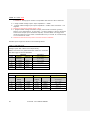
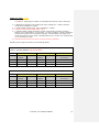
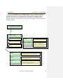
1
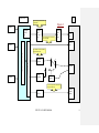
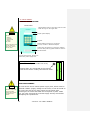
STYLITIS-101 USER'S MANUAL Copyright 1999-2014, The Symmetron Company. Sixth Edition, June 2014. No part of this publication may be reproduced, stored in a retrieval system, or transmitted, in any form by any means, without the prior written permission of Symmetron Company. Information furnished by Symmetron is believed to be accurate and reliable; however, no responsibility is assumed for its use. No license is granted by implication or otherwise. Symmetron is a registered trademark and Stylitis is a trademark of the Symmetron Company. All other trademarks belong to their respective owners. WARRANTY The Symmetron Company warrants its products shall be free from defects on materials and workmanship under normal use for the period of 1 year. Symmetron's obligation under this warranty shall not arise until buyer returns the defective product, freight prepaid to Symmetron's facility or another specified location. The only responsibility of Symmetron under this warranty is, at its option, to replace or repair, free of charge, any defective component of such products. THE WARRANTY DOES NOT EXTEND TO AND SHALL NOT APPLY TO: 1. Products which have been repaired or altered by other than Symmetron's personnel, unless Buyer has properly altered or repaired the products in accordance with procedures previously approved in writing by Symmetron. 2. Products, which have been subject to misuse, neglect, accident, improper installation, or direct lightning strikes. THE WARRANTY AND REMEDIES SET FORTH ABOVE ARE IN LIEU OF ALL OTHER WARRANTIES EXPRESSED OR IMPLIED, ORAL OR WRITTEN, EITHER IN FACT OR BY OPERATION OF LAW. THE SYMMETRON COMPANY SHALL HAVE NO LIABILITY FOR INCIDENTAL OR CONSEQUENTIAL DAMAGES OF ANY KIND ARISING OUT OF THE SALE, INSTALLATION, OR USE OF ITS PRODUCTS. RETURN OUTSIDE GREECE Contact Symmetron for authorization and shipping instructions. SYMMETRON ELECTRONIC APPLICATIONS TEL: (+30)-2106034002 FAX: (+30)-2106034003 e-mail: [email protected] Internet: http://www.symmetron.gr Made in Greece. 2 STYLITIS -101 USER'S MANUAL Σχόλιο [N1]: CONVENTIONS USED IN THIS MANUAL Symbol CAUTION Meaning To avoid injury of personnel and/or damage to the instrument the operator must refer to the user’s manual. Calls attention to a procedure or condition which, if not correctly performed could result in damage to the instrument. 1> Represents a menu item in the display. [1] Represents a key in the front panel N. Hadzidakis – T. Katsabakou Co. 26, Pipinou St. 19027 Pikermi, Greece MANUFACTURER’S DECLARATION OF CONFORMITY I, the undersigned, hereby declare that the equipment specified conforms to the below Directives and Standards. Standards to which Conformity is Declared EMC Emmisions: ΕΝ55022, EN61000-4-3 EMC Immunity: EN61000-4-2, EN61000-4-4, EN61000-4-5, EN61000-4-6 Safety: EN61010-1 Description of Equipment Data recording and logging instruments. Model Stylitis-101 Batch of product covered Serial numbers: from 50 to 2000 Date and Place Pikermi, Attica, Greece, December 31, 2002. Authorized signatory on behalf of the manufacturer N. Hadzidakis Name: N. E. Hadzidakis Title: Director N. Hadzidakis – T. Katsabakou Co. STYLITIS -101 USER'S MANUAL 3 CONTENTS 1. INTRODUCTION ............................................................................. 6 2. USE & SAFETY ............................................................................ 10 3. USER INTERFACE & FUNCTIONS SUMMARY .......................... 11 4. POWER MANAGEMENT .............................................................. 13 5. MEASUREMENTS ........................................................................ 14 6. OUTPUTS ..................................................................................... 14 7. INPUTS ......................................................................................... 15 8. MATH PROCESSING ................................................................... 19 9. TIME SERIES OPERATION.......................................................... 19 10. DATA STORAGE/RETRIEVAL................................................... 20 11. RECORDING & FILING SYSTEM............................................... 22 12. DATA POST PROCESSING ....................................................... 23 13. DATA SAFETY ........................................................................... 25 14. PASSWORD ............................................................................... 25 15. COMMUNICATION VIA THE SERIAL PORT ............................. 26 16. SOFTWARE INSTALLATION ..................................................... 27 17. TECHNICAL SPECIFICATIONS ................................................. 28 APPENDIX A APPENDIX B INPUT MODULES .............................................. 29 SCREW TERMINALS-CONNECTION EXAMPLES 38 APPENDIX C STYLITIS-101 MENU TREE .............................. 39 4 STYLITIS -101 USER'S MANUAL APPENDIX D APPENDIX E MODEM 41 STYLITIS-101 DATA RECORDING ................... 40 STYLITIS-101 GSM STYLITIS -101 USER'S MANUAL 5 1. INTRODUCTION Stylitis-101 is designed to make the collection of technical measurements easy and safe. As such, it allows you to: Communicate through the built-in display and keyboard. Connect various types of industry-standard sensors like Low-voltage bridge sensors, 4~20mA-output sensors, frequency-output sensors, anemometers, vanes, pyranometers, thermometers, etc. Program a time interval, over which the instrument will perform mathematical operations, including minimum, maximum, average and standard deviation. (Math mode). Program the sampling rate at 1,2,4,8,16 or 32Hz, individually for each input. (Time-series mode). Store the input data or math results in the internal buffer or in external (removable) Compact Flash memory cards. Use the serial interface to download buffer contents or as a substitute for the built-in display and keyboard. The above operations are performed simultaneously without affecting the integrity of the acquired data (see block diagram, Figure 1. USING STYLITIS-101 The Stylitis family of data loggers can operate in several different ways, depending on your application (refer to Figure 2): 1. As a stand-alone unit. You can leave the logger unattended for weeks or months, conditioning and recording input signals. Data are compressed and stored in the internal buffer or in removable Compact Flash 6 STYLITIS -101 USER'S MANUAL cards. If the card is not new or if it has not been used only in the specific datalogger, it induces the user to press button [1] to clear the card. Cards can be replaced without interrupting the acquisition process. Using the supplied software (Opton 4) one can read the card via a Compact Flash reader and convert compressed data to ASCII text files organized in columns for further processing. 2. As a stand-alone unit with on-line data transfer. Storage is done as above. Data are transferred to the PC for further processing via the serial port. Connection between the logger and the PC can be done using a serial cable, a modem (wired or wireless) or a LAN. A COM port, a modem or an Ethernet adapter, respectively, is required on the PC. The supplied Stylitis software is used for the above operations, as well as, the conversion of compressed data to ASCII text files. 3. As an on-line front-end unit. It conditions, samples and transfers signal measurements on-line to a computer for further processing and storage. The user’s program issues a command, which is used to transfer data. Connection between the logger and the PC can be done using a serial cable, a modem (wired or wireless) or a LAN. See 4. POWER… For a detailed description read the following pages. Technical support is available at (+30)-2106044084 or e-mail address [email protected] STYLITIS -101 USER'S MANUAL 7 Figure 1: Block Diagram SRAM LC Display Li Bat Real Time Clock Compact Flash Socket 6 counter inputs: C1~6 RS232 Counter circuits CPU 18 voltage or current inputs: AN1~18 ADC Input / Output Protection Keyboard Internal Supplies DAC Int. Bat. REG & Volt REF Digital 7~15VDC Ext. Bat. 6 voltage or current outputs: ExcOut1~6 3 digital inputs: D1~3 3 fixed voltage +5V outputs Stylitis-40/100 PC Use a memory card to store and transfer data. Figure 2 Sensor 1 COMPACT FLASH slot Memory card (Compact Flash) Use a cable (up to 15 m) to set-up and transfer data. Compact Flash card reader USB port RS-232 port Sensor 2 Use a standard or cellular modem to set-up and transfer data. RS-232 port Internal memory buffer Sensor n Standard modem Modem GSM modem Base station Use a LAN (up to 200m) and TCP/IP to set-up and transfer data. Serial server STYLITIS -101 USER'S MANUAL Ethernet 10baseT adaptor 9 2. USE & SAFETY EXTERNAL DESCRIPTION. Front Panel Compact Flash memory card slot. Push the card in with the logo on the upper side. CAUTION Liquid crystal display. Do not: - destroy - overheat - short-circuit - charge dry cells. Keypad. RS232, D9Μ connector for connection to a PC, modem or Ethernet adapter. If the instrument will not be used for a long time, remove the dry cells. 2xPP3 (9V) cell drawers. To open the drawers pull out while pushing upside. Alkaline cells are recommended. 4x front panel screws. Remove to replace the power supply fuse. BOTTOM Ground bolt. It is connected to the internal instrument shield. Usually connected to earth. TOP Box right-side panel (Terminal description inside box cover) FUSE REPLACEMENT. CAUTION The fuse used must of the specified rating. Never shortcircuit the fuse holder. The instrument uses a 315mA power supply fuse, which must be replaced if blown (supply voltage out of limits). It can be found on the upper-left side of the main printed circuit board, after removing the 4 screws that hold the front panel in place. Make sure you have removed the external supply and dry cells before attempting the replacement. 10 STYLITIS -101 USER'S MANUAL KEY SEQUENCE 3. USER INTERFACE & FUNCTIONS SUMMARY (See also APPENDIX C) Use the display/keyboard to: 1> | 1> Check firmware version. 1> | 2> Check battery voltage (due to a protection, diode internally the battery voltage measures about 0.6V less than actual value). The logger operates with internal voltages greater than 6.25VDC and less than 15VDC. 1> | 3> Check COMPACT FLASH card status and remaining capacity. COMPACT FLASH memory cards may be used to hold large amounts of data. See 10. DATA… 1> | 4> Check buffer status and remaining capacity. See 10. DATA… 1> | 5> Verify system activity. This is a summary of basic settings. 2> | 1> Either setup an averaging interval. See 8. MATH… Or setup sampling rates. See 9. TIME SERIES… 2> | 2> Setup input parameters. See 7. INPUTS 2> | 3> Setup Energy Save or Continuous logger operation mode. This menu also selects the ‘PC SYNC’ operation - see 4. POWER… 2> | 4> Setup acquired data processing: Store sampled Inputs (Time Series) or perform statistics (Math). 2> | 5> Display and change the internal Real Time Clock time/date (key-in new values). 2> | 6> Enter the site identification in alphanumeric characters. Use the dot [.] to change the keyboard character set. STYLITIS -101 USER'S MANUAL 11 2> | 7> Set/Clear the Password. Enter all zeroes to disable password. See 14. PASSWORD 3>|1> 2> 3> Display the current value of an input and the minimum, maximum and average of the last interval (in math mode). 4> | 1> Download measurement data via the RS232 port - see 15. COMMUNICATION 4> | 2> Check for existence of a modem. If a GSM modem is connected display network operator and signal level. 4> | 3> Check a SIM card’s PIN. ‘READY’ is displayed if SIM is ready for use, otherwise a valid SIM PIN is asked for. Then, the logger will unlock the SIM card. 5> Start or Stop ACQuisition. In stopped acquisition state no data are recorded and the internal buffer is cleared. See 11. RECORDING… 12 To select a menu item use the corresponding numeric key. [ESC] goes one menu-level up and abandons changes. [ENTER] goes one menu-level up and saves changes. You can change parameters only if ACQUISITION is OFF. STYLITIS -101 USER'S MANUAL 4. POWER MANAGEMENT Three operating modes are available: ENERGY SAVING MODE This is the default operating mode. The unit is in standby mode and is awakened once per second to measure, calculate and store results. This results in long battery life, since it is active only one 50th of the time. The LCD is off. Depressing a key for at least one second activates the LCD display, allowing interface with the user. Stylitis-101 automatically reverts to standby mode if there is no user activity for about 1 minute. CONTINUOUS OPERATION MODE This mode holds the unit continuously activated, thus greatly reducing battery life. However it is useful if you want to continuously display an input for checking purposes. Continuous mode is also enforced when a sampling rate faster than 1Hz is selected. When set for continuous operation, Stylitis-101 does not automatically switch to standby mode. You will have to manually set the operation mode back to 'Energy Save'. PC SYNC MODE ‘PC SYNC’ enables on-line operation with a computer connected to the serial port. A user software can setup the logger and read measurement data in real-time. This is done simultaneously and does not intervene with data logging. For more information refer to application notes AN100-3 and AN100-4. STYLITIS -101 USER'S MANUAL 13 5. MEASUREMENTS Stylitis-101 is capable of directly measuring voltage, current, For specifications see chapter 17. For connection examples refer to APPENDIX B. resistance, frequency and events. With suitable sensors the above electrical quantities are translated to: Wind speed, direction and wind-turbine power curves. Interfaces to virtually every type of anemometer and wind vane. Temperature, humidity, pressure. Solar radiation, rain height, water speed, water level, etc. Sensors must provide an analog voltage, an analog current or a frequency signal in the range of 0~5kHz. 6. OUTPUTS You can program the outputs using this sequence: 2>SETUP | 2>IN | 4>Vexc or ExcOUT. The programmable analog excitation outputs (V. EXC or EXC OUT) are capable of supplying voltage up to a TOTAL of 100 milliamps or current up to 5mA each, with an accuracy of 0.2%, see APPENDIX A. In ENERGY SAVE mode, all these outputs are pulsed to conserve battery power. They are on for about 5 milliseconds every 1 second. Thus the average current drawn from the battery (in addition to the one listed in the specifications) is 1/200th the total analog supply current Similarly, the counter supply outputs (+5V FIXED) can supply CAUTION Do not apply an external voltage to the instrument outputs. In CONTINUOUS mode the outputs are constantly ON. up to a TOTAL of 10milliAmps with an accuracy of 5%. These outputs are not pulsed. Thus, the average current drawn from the battery is the same as the total counter supply current. 14 STYLITIS -101 USER'S MANUAL 7. INPUTS Inputs are set by selecting the IN option from the SETUP menu. To setup vane and analog input parameters: Select an input, 01-18. Then use [] or [] to select option. ANALOG INPUTS The analog section has from 0 to 18 inputs, depending on the number of analog modules installed. The resolution is 12 bits. INPUTS 1-18. Input modules, as described in APPENDIX A, define the characteristics of analog inputs. The following options however are generally available on all inputs: NOT USED. User selectable 1>SLOPE and 2>OFFSET values are applied on acquired data: Scaled input = (slope x input voltage) + (offset). Math operations are performed on scaled inputs. These include minimum, maximum, average and standard deviation. The input can also be set to 3>UNIPolar or 3>BIPolar mode for unipolar or bipolar signals. The 4>FS (full scale) selection allows for hardware amplification of input CAUTION Do not apply a voltage exceeding the maximum permissible (20V) on voltage inputs. Do not apply a current exceeding the maximum permissible (100mA) on current inputs. signals from 1~1000 times. Remember, however, that the input signal MUST NOT exceed the FS selection (see APPENDIX A). VANE input, for wind direction measurements (only for low-voltage inputs). An input voltage between 0V and 5V corresponds to an angle of 0~360 degrees with a resolution of 1.4 degree (VANE type has 8 bit resolution). Math operations include vector minimum, maximum, average and standard deviation. Vane math is NOT the STYLITIS -101 USER'S MANUAL 15 arithmetic average; a vector-averaging algorithm is used to ensure true calculation of angle averages. The user can freely set the zero degree offset in degrees (0~359). This is the actual vane zero in respect to the north. For instance, if the vane “zero” mark is placed 30 east then you enter 30 as offset; if it is placed 30 west you enter 330 (=360-30) as offset. 4. TEMPERATURE PT100. The logger is connected to a PT100 RTD temperature sensor as shown in APPENDIX B. Linearization is performed internally throughout a range of -50C~+150C. Math is performed as above. ADVANCED APPLICATIONS OF ANALOG INPUTS. BRIDGE CONNECTION In the ‘SLOPE & OFFSET’ menu, you can use the dash [-] to switch input type between PLAIN INPUT (A) and BRIDGE (B). A bridge connection changes a module’s type to work as follows: The first differential voltage channel (i.e. ANALOG1) is used for See APPENDIX B for connection example. measuring the bridge output. The second differential voltage channel (i.e. ANALOG7) is used as a sense connection for the excitation voltage to ensure that it has the correct value on the sensor’s terminals despite the length of the connecting cables. For many bridge-type sensors it is useful to zero the output when in steady state. Use the menu keys to display the channel used as bridge input (i.e. ANALOG1). Then push the [0] key to start the Auto-Zero process. This automatically adds a small current to one bridge arm in order to balance it’s output to zero. If you want to cancel the Auto-Zero balance action press the dash [-] key. 16 STYLITIS -101 USER'S MANUAL To setup anemometer and counter parameters: Select an input, 1-6. Then, use [] or [] to select option. COUNTING INPUTS. The counter section has from 3 to 6 inputs, depending on the number of analog modules installed. The resolution is 16 bits (0~65535 counts). INPUTS 1~3. These are built-in counting inputs. Input threshold is selectable: low-level AC (SIN) or pulse (TTL) type. Resolution is 0.5Hz. INPUTS/OUTPUTS 4~6. Optional plug-in modules, as described in APPENDIX A make these channels either counter inputs or state outputs. The following options are available on all modules with counter inputs: From the TYPE menu press the corresponding numeric key to change anemometer or counter input type between Low Level AC (SIN), Digital (TTL) or Switch (REED). NOT USED. ANEM input. Input frequency (counts per second) is scaled with user selectable slope and offset values: Wind speed (km/h) = (slope x input frequency) + (offset). Math operations include minimum, maximum, average and standard deviation. Output (calculated) range: 0~400.0 user-defined units. Resolution is 0.1 units. Examples of units are m/sec, km/h, etc. The anemometer’s manufacturer gives slope and offset values. For instance, the NRG-Maximum #40, has a slope = 0.765 m/sec/Hz, and an offset = 0.35. STYLITIS -101 USER'S MANUAL 17 FREQUENCY COUNTER. Slope and offset are fixed at 1.0 and 0.0 respectively. Math operations include minimum, maximum, average. CAUTION EVENT COUNTER. Counts events (pulses) per averaging period (1 minute through 1hour). Do not apply a voltage exceeding the maximum permissible (20V) on counter or digital inputs. DIGITAL INPUTS. This is a group of 3 digital inputs (state inputs 1/0 corresponding to 5V and 0V). The available options are USED and NOT USED. If USED is chosen they are stored as a byte with bits 2:0 representing digital inputs 3, 2, 1 respectively (bits 7:3 are always zero). Math operations include minimum and maximum. 18 STYLITIS -101 USER'S MANUAL 8. MATH PROCESSING The analog and counting inputs selected are measured and temporarily stored once per second. Averaging intervals are selectable at 1, 2, 5, 10, 15 or 60 minutes. Following the completion of an averaging interval, the math functions are performed and the results are stored in the internal buffer or the COMPACT FLASH card. See also, 7. INPUTS… Math calculations include minimum, maximum, average and standard deviation. The standard deviation is calculated using the formula: SDV = x2 n AV 2 , where n is the number n n 1 of the samples and AV the average of the samples in the averaging interval. Stored data format for the various input types is: ANEM FREQ ANALOG VANE ANALOG Minimum xxx.x xxx xxx.x xxxx.xxx Maximum xxx.x xxx xxx.x xxxx.xxx Average xxx.xx xxx.x xxx.x xxxx.xxx SDV xxxx.xxx xxx.x xxxx.xxx The stored data have are marked with a time stamp for extra protection. The time stamp marks the end of the statistic interval. 9. TIME SERIES OPERATION. Input values are sampled, scaled and stored. Math is not performed. The sampling rate for each channel is user selectable, and takes one of the following values: 1, 2, 4 ,8, 16 or 32 Hz. Stylitis-101 is automatically switched to ‘Continuous’ mode for sampling rates greater than 1. STYLITIS -101 USER'S MANUAL 19 Although each channel separately can have its own sampling rate (up to 32Hz), for the datalogger’s proper operation, not all channels can sample simultaneously at 32 Hz. The channels are 25: 6 counters, 18 analog channels and 1 digital (the 3 digital ones are calculated as 1, see 7.INPUTS) It is recommended that the sum of the frequencies of the used channels does not exceed the number 200. E.g., if all channels are used and are sampling at 8 Hz, the sum is 8x25=200. 10. DATA STORAGE/RETRIEVAL Three types of storage media can be used, each one having its own strengths. INTERNAL BUFFER. The internal buffer's size of 512Kbytes is enough for several applications. For example, to record data using one anemometer and one vane, with a 10min-averaging interval, it will suffice for 212 days. A memory card is NOT permanently required, thus reducing operating costs. Data can be retrieved two ways: 1. By placing, for a few seconds, a compatible memory card (see below) in the slot. Data are transferred to the card and recording continues uninterrupted. 20 During the acquisition in the internal buffer (with no card), you can put a card in the datalogger and clear it, if it is not clear, via the [1] button. Only after that data will be able to be recorded in the card. Then, the data which have already been recorded in the internal buffer will be transferred in the card almost immediately. That is, either the ‘CARD ERASED ok’ message will appear in the datalogger’s screen, in case you clear the card, or the message indicating its size will appear, along with an ‘ok’. Right next, the ‘TRANSFERING DATA’ message will appear. When it disappears, you can remove the card. If you do not,, the file which has been created in the card, and contains these data, will continue to be recorded. μεταφερθούν στην κάρτα, αλλά θα παραμείνουν στην εσωτερική μνήμη. STYLITIS -101 USER'S MANUAL 2. By downloading buffer contents through the serial port, see 15. COMMUNICATION… ADVANTAGES: Low Operational Costs. DISADVANTAGES: Restricted size. COMPACT FLASH MEMORY CARDS The size of the above cards is enough for virtually all applications. (E.g. for data of one anemometer and one windvane, with a 10 minute interval, a 256 Μbytes card will last for 3737 months). Each time a new card is inserted in the datalogger, it must be cleared. The datalogger warns you with the corresponding message and induces you to do so by pressing the [1] button. Τhe card is recognized and initialized by inserting it into the Stylitis-41 slot. A header is put on it including a serial number, the site name and the insertion time. Therefore, if you remove the card and re-insert the same one later, it will be recognized by the datalogger and you will not need to clear it. By inserting the card in the slot of a Compact Flash card reader, connected to a computer USB port, data are retrieved via the Opton 4 software. ADVANTAGES: High capacity. Low cost. No Battery. DISADVANTAGES: None. STYLITIS -101 USER'S MANUAL 21 11. RECORDING & FILING SYSTEM Starting (ON) acquisition means: When acquisition is on: No parameter change is 1. Open a new file on a memory card (if one exists). allowed. 2. Start recording with the set parameters. Stopping (OFF) acquisition means: When acquisition is off: Parameter change is 1. Stop recording. allowed. 2. Close the file on a memory card (if one exists). 3. Clear the internal buffer. When using memory cards keep in mind the following tips: 1. Multiple files (acquisition sessions) can exist on the same card. If you stop the current acquisition and start a new one, a new file is created with a new number and a new start date and time. 2. Full cards are replaced without loss of data and without turning OFF the acquisition. In the meantime, data are kept in the buffer. 3. Accidentally removing and reinserting a card does not result in data loss. The system recognizes it is the same card and (provided there is space) continues storing data in a new file. Only the lastly inserted card is recognized by the system. You can withdraw and reinsert the same memory card as many times as you wish. But changing the Compact Flash card means that recognition and initialization of a card is done only if the card is new and not used. Otherwise, the datalogger induces you to clear it by pressing the [1] button (refer to: 10. DATA STORAGE…). 22 STYLITIS -101 USER'S MANUAL 12. DATA POST PROCESSING A card’s recorded data are transferred to a PC for processing when you insert the card to the slot of a Compact Flash card reader, connected to a computer USB. To save space, data are stored compressed. Moreover, the data can be retrieved directly from the datalogger, via its serial port, either locally or via modem (see 15. COMMUNICATION VIA THE SERIAL PORT). Via Opton 4 software, you can download data either from the internal buffer or from the card (if there is one). When you download data from the internal buffer, (with no card), with acquisition ON, after the download, Opton 4 asks you if you wish to clear it or not. In the second case, the recording will be continued, by incrementing the size of the internal buffer’s data file. The ‘BUFFER REMAINS’ message will appear in the datalogger’s screen. When you download data from the card, there are two options: 1. To download a previous file, by typing its number in the Opton 4’s window. In this case, if the acquisition is ON, then the recording in the current file continues uninterrupted (it is not affected by the download). 2. To download the Compact Flash (files) Directory. Afterwards, you may mark specific files from the directory to download. Again, if the acquisition is ON, then the recording in the current file continues uninterrupted (it is not affected by the download). 3. To download the most recent file (‘Most recent file’ option). In this case, if the acquisition is ON, the file closes before it is downloaded and then it is downloaded. After it has closed, a next file opens (is created), in which the acquisition continues. STYLITIS -101 USER'S MANUAL 23 Data records are decompressed to columns using Stylitis, a PC program that comes with the unit. Further data manipulation and processing is possible using standard available software like Excel, Axum, etc. ‘Windrose’, an optional software suitable for Wind/ Meteorological analysis is also available. It accepts the decompressed output and produces graphs, tables, etc. in industry-standard format. Please contact Symmetron for details. Windrose graph 5 11 wind speed (m/s) 17 23 NNE ENE ESE WSW WNW SSE SSW Turbulence Intensity (%) 18 16 14 12 10 8 6 4 2 0 NNW Wind Direction 24 STYLITIS -101 USER'S MANUAL 13. DATA SAFETY To ensure correct data acquisition and protect stored data and settings the Power Supply is continuously checked. If battery voltage is found to be less than 6.25V then acquisition stops. The acquisition restarts when battery voltage rises above 6.75V. If battery voltage falls below 5.15V the system shuts down and stops responding to external stimuli. 14. PASSWORD Stylitis-101 allows you to set a password in order to permit access to it from qualified persons only. Using the SETUP> PASSWORD menu enter an alphanumeric word of up to 8 characters long (press [.] to enter alpha characters). Password protection starts after the password is set and Stylitis enters Energy-Save mode. Any attempt to wake-up the data logger will result in asking for the password. If the correct password is not supplied within 4 tries, the logger will lock-up and can only be unlocked by Symmetron (either locally or remotely). To disable the password protection you must enter 8 dashes [-] or zeroes [0]. STYLITIS -101 USER'S MANUAL 25 15. COMMUNICATION VIA THE SERIAL PORT To connect to a standard PC serial port a The RS-232 serial port comes as standard with Stylitis-101. It allows local or remote set-up and buffer data retrieval (it also "straight" type allows Logger-to-PC on-line operation, see 4. POWER…). The user cable is required, interface, as appears on the PC screen is identical to that on the i.e. one, which connects pin 2 of data logger. one connector to The connector is a DB9Male with the following pin assignment: pin 2 of the PIN 2 Transmit PIN 3 Receive PIN 5 Ground other, etc. Communication speed is fixed at 9600 baud with 8 data bits, 1 stop bit and no parity bit. For the communication of Stylitis and the PC, connect the datalogger’s serial port to a computer COM port via a DB9F to DB9F (female-female) straight cable. Next, run the Opton 4 software, by creating a local connection via the specific COM port to communcicate with the datalogger. You can also use a modem, by connecting it to the serial port via a NULL MODEM cable for remote communication with Stylitis (see APPENDIX E). Furthermore, you can use Symmetron’s Symo-net, by connecting the datalogger’s serial port to the DEVICE 1 port of the Sym-o-net, via a NULL MODEM DB9F to DB9M (femalefemale) cable. In this case, create a Diameson (GPRS client) connection via Opton 4. For further information about the Sym-o-net and its settings and capabilities, please refer to its User Guide. 26 STYLITIS -101 USER'S MANUAL 16. SOFTWARE INSTALLATION For software installation and using instructions refer to the README.TXT file on the 1st diskette or CD supplied with the unit. STYLITIS -101 USER'S MANUAL 27 17. TECHNICAL SPECIFICATIONS ΙNPUTS Each individually selectable: ANALOG plug-in (A1~A12): 12 differential inputs, 12bit each. For input specifications see Appendix A. ANALOG plug-in (A13~A18): 6 single-ended inputs, 12bit each. For input specifications see Appendix A. COUNTING built-in (C1~C3): 3 inputs, 16 bit each. Resolution 0.5Hz (2 counts per period). Accuracy 1 count. Input range: 0~5kHz. Input impedance: 1MΩ. Sensitivity: 100mV (SIN), 2V (TTL). Maximum continuous input: 20V COUNTING/OUTPUT plug-in (C4~C6): 3 inputs, 16 bit each. For input specifications see Appendix A. DIGITAL built-in: 3 TTL inputs, 1 bit each. Selectable as a group. Input impedance: 100kΩ. Sensitivity: 2V. Maximum continuous input: 20V OUTPUTS (SENSOR SUPPLY) 3 built-in, fixed 5V. Maximum total output current: 10mA. Accuracy 5%. Maximum continuous time, short-circuit to Ground: indefinite. Pulsed 0~6 depending on analog plug-ins. For specifications see Appendix A. PROTECTION All inputs/outputs are protected from transient overvoltages with spark gap arrestors and high-speed diodes. SENSOR EXAMPLES Voltage, current, frequency, anemometers, vanes, pyranometers, thermometers, rain level, water speed, barometric pressure, pulse counting, etc, DATA STORAGE INTERNAL BUFFER: 512Kbyte). Typical capacity (1 analog and 1 counting input, 10 min averaging): 212 days. Compact Flash MEMORY CARDS: up to 2Gbytes, FAT16 formatted. DATA PROCESSING Math mode: Individually programmable slope and offset for each input. Sampling @ 1 Hz. Calculation and storage of Minimum, Maximum, Average and Standard Deviation selectable @ 1, 2, 5, 10, 15 or 60 minute intervals. Time series mode: Individually programmable slope and offset for each input. Individually programmable Sampling rate @ 1, 2, 4, 8, 16, 32 Hz. Real Time Clock with automatic lap year correction. Accuracy: 1 minute/ month. SERIAL PORT PROGRAMMING AND DATA TRANSFER: RS232C port. 9600 baud, 8 bits, no parity, 1 stop bit. Socket is DB9M. Supports modems and Ethernet (LAN) adapters. POWER SUPPLY INTERNAL BATTERY: 2x9V alkaline- typical life 2 weeks (Math mode, 10-min intervals). EXTERNAL: 6~15V, DC/AC typical consumption 1.5mΑ (LCD off) or 50mA (LCD on). Maximum continuous power supply voltage: 18V OPTIONAL: PV panel and internal rechargeable battery. 28 STYLITIS -101 USER'S MANUAL VARIOUS ENCLOSURE: ΙΡ65 sealed. DIMENSIONS: 31x21.5x17.5cm. WEIGHT: 4kg. CONNECTORS: Removable screw terminal strips on side. OPERATING/STORAGE TEMPERATURE: -30C~ +70C LCD OPERATING TEMPERATURE: 0-50C Module position on motherboard Counter 4 Counter 5 Counter 6 Analog 1 Analog 2 Analog 3 Analog 4 Analog 5 Analog 6 STYLITIS -101 USER'S MANUAL 29 APPENDIX A INPUT MODULES A.1 COUNTER INPUTS. A plug-in module conditions 1 counter input or output. CARD-21. Color: Blue A 'CARD21' counter input module is compatible with slots C4, C5 and C6. It features: Counter length 16 bits. Resolution 1Hz. Accuracy 1 count. Input range: 0~5kHz (TTL), 0~50Hz (REED). Input impedance: 100kΩ. Sensitivity: 2V. Maximum continuous input: 20V CARD-22. Color: Brown A 'CARD22' counter input module is compatible with slots C4, C5 and C6. It features: Counter length 16 bits. Resolution 1Hz. Accuracy 1 count. Input range: 0~5kHz. Input impedance: 1MΩ. Sensitivity: 100mV (SIN), 2V (TTL). Maximum continuous input: 20V CARD-25. Color: Black A 'CARD25' output module is compatible with slots C4, C5 and C6. It features: 30 ‘Open collector’ output. Output resistance <0.5Ω Maximum sink current 200mA with internal resetable fuse. Maximum output voltage: 30V (transzorb protected). STYLITIS -101 USER'S MANUAL A.2 ANALOG INPUTS. A plug-in module conditions 3 analog inputs. The 1st analog input has a channel number equal to the slot number. The 2nd input’s channel number is equal to the 1st plus 6. The 3rd input’s channel number is equal to the 2nd plus 6. For example a module plugged in Slot A2 has channel numbers of 2, 8 and 14. The following table shows the channel configuration for all analog slots: LOCATION Of module in motherboard: CHANNELS 1~6 CHANNELS 7~12 SLOT A1 Set as 'A': Differential Set as 'B': Bridge CH1 A: differential input Dependent on left column setting CH7: differential input SLOT A2 CH1 B: bridge input CH2 A: differential input CH7: bridge sense CH8: differential input CH2 B: bridge input CH3 A: differential input CH3 B: bridge input CH4 A: differential input CH8: bridge sense CH9: differential input CH9: bridge sense CH10: differential input CH4 B: bridge input CH5 A: differential input CH5 B: bridge input CH6 A: differential input CH6 B: bridge input CH10: bridge sense CH11: differential input CH11: bridge sense CH12: differential input CH12: bridge sense SLOT A3 SLOT A4 SLOT A5 SLOT A6 CHANNELS 13~18 Independent CH13: Single-ended CH14: Single-ended CH15: Single-ended CH16: Single-ended CH17: Single-ended CH18: Single-ended To select A or B type: go to one of the first 6 channels setup menu and use the [-] key. Outputs are numbered according to the module number i.e. ExcOUT3 corresponds to a module in slot A3. STYLITIS -101 USER'S MANUAL 31 CARD-11. Color: Red A 'CARD-11' analog input module is compatible with slots A1~A6. It features: 2 differential voltage inputs. Differential input impedance: >10ΜΩ. Vane resolution: 1.4 degrees. Maximum continuous voltage input: 20V 1 single-ended current input. Input impedance 35Ω. Maximum continuous current input: 100mA 1 programmable voltage-excitation output (referenced to common ground). Range: 0~5V. Resolution 0.1V. Accuracy: (0.2% of setting)+(5mV). Maximum total current output (all V-Excitation outputs): 100mA. In ‘Energy Save’ mode the output is on for about 5 milliseconds every 1 second. It is continuously on in ‘Continuous’ mode. Maximum continuous time, short-circuit to Ground: indefinite. For bridge (6-wire) connection the second voltage channel is used as a voltage sense input for the excitation output (see connections in APPENDIX B). This ensures correct voltage on bridge terminals. Possible input ranges are shown in the following tables: TYPE A: DIFFERENTIAL VOLTAGE. Voltage inputs AN1~AN12 used independently. TYPE B: VOLTAGE BRIDGE. Voltage inputs AN1~AN6 used together with inputs AN7~AN12 in 6-wire bridge connection. UNIPOLAR BIPOLAR RESOLUTION INPUT 1 0~+5V 1.22mV 5V 2.44mV 0.15 + 0.04 10 0~+0.5V 122μV 0.5V 244μV 0.2 + 0.04 100 0~+0.05V 12.2μV 0.05V 24.4μV 0.2 + 0.4 1000 0~+0.005V 1.22μV 0.005V 2.44μV 0.2 + 2 RANGE INPUT RESOLUTION ACCURACY GAIN RANGE (% of reading + % of range) SINGLE-ENDED CURRENT: Current inputs AN13~AN18 used independently. UNIPOLAR BIPOLAR RESOLUTION INPUT 10 0~+20mA 4.88μΑ 20mA 9.76μΑ 0.0 + 0.4 100 0~+2mA 488nΑ 2mA 976nΑ 0.0 + 2 1000 0~+0.2mA 48.8nΑ 0.2mA 97.6nΑ 0.0 + 20 RANGE 32 INPUT RESOLUTION ACCURACY GAIN RANGE (% of reading + % of range) STYLITIS -101 USER'S MANUAL CARD-12. Color: Green A 'CARD-12' analog input module is compatible with slots A1~A6. It features: 2 differential voltage inputs. Differential input impedance: >10ΜΩ. Vane resolution: 1.4 degrees. 1 single-ended voltage input. Input impedance: >10ΜΩ. Vane resolution: 1.4 degrees. Maximum continuous voltage input: 20V 1 programmable voltage-excitation output (referenced to common ground). Range: 0~5V. Resolution 0.1V. Accuracy: (0.2% of setting)+(5mV). Maximum total current output (all V-Excitation outputs): 100mA. When in ‘Energy Save’ mode the output is on for about 5 milliseconds every 1 second. It is continuously on in ‘Continuous’ mode. Maximum continuous time, short-circuit to Ground: indefinite. For bridge (6-wire) connection the second voltage channel is used as a voltage sense input for the excitation output (see connections in APPENDIX B). This ensures correct voltage on bridge terminals. Possible input ranges are shown in the following tables: TYPE A: DIFFERENTIAL VOLTAGE. Voltage inputs AN1~AN12 used independently. TYPE B: VOLTAGE BRIDGE. Voltage inputs AN1~AN6 used together with inputs AN7~AN12 in 6-wire bridge connection. UNIPOLAR BIPOLAR RESOLUTION INPUT 1 0~+5V 1.22mV 5V 2.44mV 0.15 + 0.04 10 0~+0.5V 122μV 0.5V 244μV 0.2 + 0.04 100 0~+0.05V 12.2μV 0.05V 24.4μV 0.2 + 0.4 1000 0~+0.005V 1.22μV 0.005V 2.44μV 0.2 + 2 RANGE INPUT RESOLUTION ACCURACY GAIN RANGE (% of reading + % of range) SINGLE-ENDED VOLTAGE: Voltage inputs AN13~AN18 used independently. UNIPOLAR BIPOLAR RESOLUTION INPUT 1 0~+5V 1.22mV 5V 2.44mV 0.2 + 0.04 10 0~+0.5V 122μV 0.5V 244μV 0.2 + 0.1 100 0~+0.05V 12.2μV 0.05V 24.4μV 0.2 + 1 1000 0~+0.005V 1.22μV 0.005V 2.44μV 0.2 + 10 RANGE INPUT RESOLUTION ACCURACY GAIN RANGE (% of reading + % of range) STYLITIS -101 USER'S MANUAL 33 CARD-13. Color: Grey A 'CARD-13' analog input module is compatible with slots A1~A6. It features: 2 differential current inputs. Input impedance 35Ω. Resolution: 4.88nA~ 4.88μΑ. Accuracy: 0.2%. 1 single-ended current input. Input impedance 35Ω. Resolution: 4.88nA~ 4.88μΑ. Accuracy: 0.2%. Maximum continuous current input: 100mA 1 programmable voltage-excitation output (referenced to common ground). Range: 0~5V. Resolution 0.1V. Accuracy: (0.2% of setting)+(5mV). Maximum total current output (all V-Excitation outputs): 100mA. When in ‘Energy Save’ mode the output is on for about 5 milliseconds every 1 second. It is continuously on in ‘Continuous’ mode. Maximum continuous time, short-circuit to Ground: indefinite. Possible input ranges are shown in the following tables: TYPE A: DIFFERENTIAL CURRENT. Current inputs used independently. TYPE B: VOLTAGE BRIDGE. NOT APPLICABLE UNIPOLAR GAIN INPUT BIPOLAR RESOLUTION RANGE 10 0~+20mA INPUT RESOLUTION RANGE 4.88μΑ 20mA ACCURACY (% of reading + % of range) 9.76μΑ 0.2 + 0.1 100 0~+2mA 488nΑ 2mA 976nΑ 0.2 + 1 1000 0~+0.2mA 48.8nΑ 0.2mA 97.6nΑ 0.2 + 10 SINGLE-ENDED CURRENT. Current inputs AN13~AN18 used independently. UNIPOLAR GAIN INPUT 10 0~+20mA BIPOLAR RESOLUTION RANGE INPUT RESOLUTION RANGE 4.88μΑ 20mA ACCURACY (% of reading + % of range) 9.76μΑ 0.0 + 0.4 100 0~+2mA 488nΑ 2mA 976nΑ 0.0 + 2 1000 0~+0.2mA 48.8nΑ 0.2mA 97.6nΑ 0.0 + 20 34 STYLITIS -101 USER'S MANUAL CARD-14. Color: Blue A 'CARD-14' analog input module is compatible with slots A1~A6. It features: 2 differential voltage inputs. Differential input impedance: >10ΜΩ. Vane resolution: 1.4 degrees. 1 single-ended voltage input. Input impedance: >10ΜΩ. Vane resolution: 1.4 degrees. Maximum continuous voltage input: 20V 1 programmable current-excitation output (referenced to common ground). Range: 0~5mA. Resolution 0.1mA. Accuracy: (0.2% of setting)+(5μA). When in ‘Energy Save’ mode the output is on for about 5 milliseconds every 1 second. It is continuously on in ‘Continuous’ mode. Maximum continuous time, short-circuit to Ground: indefinite. Possible input ranges are shown in the following tables: TYPE A: DIFFERENTIAL VOLTAGE. Voltage inputs AN1~AN12 used independently. TYPE B: VOLTAGE BRIDGE. NOT APPLICABLE UNIPOLAR GAIN INPUT BIPOLAR RESOLUTION RANGE INPUT RESOLUTION RANGE ACCURACY (% of reading + % of range) 1 0~+5V 1.22mV 5V 2.44mV 0.15 + 0.04 10 0~+0.5V 122μV 0.5V 244μV 0.2 + 0.04 100 0~+0.05V 12.2μV 0.05V 24.4μV 0.2 + 0.4 1000 0~+0.005V 1.22μV 0.005V 2.44μV 0.2 + 2 SINGLE-ENDED VOLTAGE: Voltage inputs AN13~AN18 used independently. UNIPOLAR BIPOLAR RESOLUTION INPUT 1 0~+5V 1.22mV 5V 2.44mV 0.2 + 0.04 10 0~+0.5V 122μV 0.5V 244μV 0.2 + 0.1 100 0~+0.05V 12.2μV 0.05V 24.4μV 0.2 + 1 1000 0~+0.005V 1.22μV 0.005V 2.44μV 0.2 + 10 RANGE INPUT RESOLUTION ACCURACY GAIN RANGE (% of reading + % of range) STYLITIS -101 USER'S MANUAL 35 CARD-15. Color: Red A 'CARD-15' analog input module is compatible with slots A1~A6. It features: 2 single-ended voltage inputs. Input impedance: >10ΜΩ. 1 single-ended voltage input. Input impedance: >10ΜΩ. Vane resolution: 1.4 degrees. Maximum continuous voltage input: 20V 1 programmable voltage-excitation output (referenced to common ground). Range: 0~5V. Resolution 0.1V. Accuracy: (0.2% of setting)+(5mV). Maximum total current output (all V-Excitation outputs): 100mA. When in ‘Energy Save’ mode the output is on for about 5 milliseconds every 1 second. It is continuously on in ‘Continuous’ mode. Maximum continuous time, short-circuit to Ground: indefinite. Possible input ranges are shown in the following tables: TYPE A: LOW VOLTAGE. Voltage inputs AN1~AN12 used independently. NOTE: Accuracies are guaranteed when Card15 is used with the data logger that was calibrated. UNIPOLAR GAIN ΠΕΡΙΟΧΗ ACCURACY ΑΝΑΛΥΣΗ ΕΙΣΟΔΟΥ (% Of reading + % Of range) 1 0~+25mV 6.1μV 0.1 + 0.025 10 0~+2.5mV 0.61μV 0.1 + 0.8 100 0~+250μV 61nV - 1000 0~+25μV 6.1nV - SINGLE-ENDED VOLTAGE: Voltage inputs AN13~AN18 used independently. UNIPOLAR GAIN INPUT BIPOLAR RESOLUTION RANGE INPUT RESOLUTION RANGE ACCURACY (% of reading + % of range) 1 0~+5V 1.22mV 5V 2.44mV 0.2 + 0.04 10 0~+0.5V 122μV 0.5V 244μV 0.2 + 0.1 100 0~+0.05V 12.2μV 0.05V 24.4μV 0.2 + 1 1000 0~+0.005V 1.22μV 0.005V 2.44μV 0.2 + 10 36 STYLITIS -101 USER'S MANUAL CARD-16. Color: Yellow A 'CARD-16' analog input module is compatible with slots A1~A6. It features: 2 differential voltage inputs. Differential input impedance: >10ΜΩ. Common mode input impedance: 110KΩ. 1 single-ended voltage input. Input impedance: 110KΩ. Maximum continuous voltage input: 20V 1 programmable voltage-excitation output (referenced to common ground). Range: 0~5V. Resolution 0.1V. Accuracy: (0.2% of setting)+(5mV). Maximum total current output (all V-Excitation outputs): 100mA. When in ‘Energy Save’ mode the output is on for about 5 milliseconds every 1 second. It is continuously on in ‘Continuous’ mode. Maximum continuous time, short-circuit to Ground: indefinite. Possible input ranges are shown in the following tables: TYPE A: DIFFERENTIAL VOLTAGE. Voltage inputs AN1~AN12 used independently. TYPE B: VOLTAGE BRIDGE. NOT APPLICABLE UNIPOLAR BIPOLAR RESOLUTION INPUT 10 0~+50V 122μV 50V 244μV 0.5 + 0.04 100 0~+5V 12.2μV 5V 24.4μV 0.5 + 0.4 1000 0~+0.5V 1.22μV 0.5V 2.44μV 0.5 + 2 RANGE INPUT RESOLUTION ACCURACY GAIN RANGE (% of reading + % of range) SINGLE-ENDED VOLTAGE: Voltage inputs AN13~AN18 used independently. UNIPOLAR GAIN INPUT BIPOLAR RESOLUTION RANGE INPUT RESOLUTION RANGE ACCURACY (% of reading + % of range) 10 0~+50V 122μV 50V 244μV 0.5 + 0.2 100 0~+5V 12.2μV 5V 24.4μV 0.5 + 1 1000 0~+0.5V 1.22μV 0.5V 2.44μV 0.5 + 10 STYLITIS -101 USER'S MANUAL 37 APPENDIX B SCREW TERMINALS-CONNECTION EXAMPLES TOP RAIN GAUGE METER (Reed Switch) BOTTOM GROUND 7 GROUND 7 COUNTER 6 6 COUNTER 3 6 GROUND 5 GROUND 5 COUNTER 5 4 COUNTER 2 4 3 GROUND COUNTER 1 3 GROUND COUNTER 4 +5V FIXED 2 1 SYNC. IN +5V FIXED 2 1 EXTERNAL 7 GROUND 7 SYNC OUT 6 DIGITAL 3 6 BATTERY OR POWER SUPPLY: 6-15V DC 5-12V AC GROUND 5 GROUND 5 GROUND 4 DIGITAL 2 4 GROUND 3 E.BAT. SWITCHED 2 1 EXT. BATTERY + 1 GROUND DIGITAL 1 . +5V FIXED 3 + RED BAROMETRIC SENSOR (EXAMPLE: NRG BP20) WHITE BLK SUPPLY VOLTAGE DEPENDS ON TRANSDUCER 4~20 mA TRANSDUCER (EXAMPLE: SYMMETRON SDP-5) PT100 RTD 2KΩ/0.1%, 3ppm TEMPERATURE SENSOR (EXAMPLE: NRG #110S) AN 14 / CURRENT 7 +AN 2 6 AN 2 GROUND 5 AN 8 / SENSE 2 +AN 8 / SENSE 2 3 V. EXCITATION 2 BLK GREEN RED 38 1 V. EXCITATION 1 1 5 AN 10 / SENSE 4 +AN 10 / SENSE 4 3 4 2 1 AN 18 / CURRENT 7 +AN 6 6 2 ANALOG VOLTAGE POTENTIOMETRIC VANE (1~100kohm) AN 15 / CURRENT 7 +AN 3 6 AN 3 GROUND 5 AN 9 / SENSE 3 +AN 9 / SENSE 3 3 V. EXCITATION 3 4 2 1 AN 17 / CURRENT 7 +AN 5 6 5 AN 5 5 GROUND 4 GROUND 4 AN 12 / SENSE 6 +AN 12 / SENSE 6 3 AN 11 / SENSE 5 +AN 11 / SENSE 5 3 2 1 SWITCH 4 AN 6 V. EXCITATION 6 EXCITATION: 5V 3 2 AN 7 / SENSE 1 +AN 7 / SENSE 1 AN 4 GROUND V. EXCITATION 4 AN 13 / CURRENT 7 +AN 1 6 5 AN 16 / CURRENT 7 +AN 4 6 DIGITAL TYPE ANEMOMETER (5v supply, TTL output) 2 1 AN 1 GROUND 4 MAX #40 ANEMOMETER (>100mV AC) V. EXCITATION 5 PYRANOMETER 0~+40mV BRIDGE 0~5mV/V 2 1 TYPICAL 6-WIRE CONNECTION STYLITIS -101 USER'S MANUAL APPENDIX C STYLITIS-101 MENU TREE Press any key for main menu. STATUS: 1>INFO 2>BAT 3>CARD 4>BUF 5>ACTIVITY 5>ACTIVITY 1>STATUS2>SETUP3>DISPLAY 4>COMMUNICATE 5>ACQon/off 1 To see system status. 2 To set system parameters. 3 To display inputs. 4 5 (1) To download buffer-data via RS232 to PC. 1 To check Software version. 2 To check battery voltage. 4 To get internal buffer free space. 5 To check system current activity: To Start or Stop acquisition (recording) of data. To accept press [ENTER]. ACQ ON or OFF Averaging Interval (INT xx') Storage medium. SETUP: 1>RATE 2>IN 3>MODE 4>DAT 5>TIM 6> SITE 7>PAS SETUP INPUTS: 1>ANALOG 2>COUNTER 3>DIG 4>ExcOUT (1) 1 To select averaging interval. 1 3 To select continuous or energy-save operation. 4 To select input (time series) or math storage. 2 6 To give a site name (5) (alphanumeric) . To select a menu item use the corresponding numeric key. [ESC] goes one menu-level up and abandons changes. [ENTER] goes one menu-level up and saves changes. You can change parameters only if ACQUISITION is OFF. To setup counter and anemometer parameters. Select an input, 1-3. Then use [] or [] to select option: Not used Anemometer slope, offset(3) Frequency counter Event counter 5 To set time and date. 7 To set the password. To setup analog and vane input parameters. Select an input, 1-4. Then use [] or [] to select option: Not used PT100 (temp) Vane input (2) Analog input slope, offset (3) 2 To setup inputs' parameters. To get card type and free space. To clear card. 3 3 To select digital inputs: Use [] or [] to select option: Not used Used 4 To set excitation outputs. Select an input, 1-6 Key-in a new value. NOTES: (1) Use [ ] or [ ] to select. (2) Use [—] to select vane zero point. (3) Use [1] or [2] to select fields.STYLITIS -101 USER'S MANUAL 39 (4) Press corresponding numeric key to change anem or counter type between Low Level AC (SIN) and Digital (TTL). (5) Press [.] to use numerals as letters. APPENDIX D STYLITIS-101 DATA RECORDING DATA RECORDING WITH A CARD ACTIVITY DISPLAY ACQ ON Data in card Data are stored in card. If the card is full, data are stored in internal buffer. Data recording (acquisition) is stopped when buffer is full. ACQ ON Data in Buffer Card full ACQ ON Card full Buffer full Insert a new card to get data from buffer. Recording continues with no interruption. If buffer was full, recording starts automatically again as a new session. DATA RECORDING WITH NO CARD Data are stored in internal buffer. Data recording (acquisition) is stopped when buffer is full. To get data from buffer: Insert a memory card to transfer data and clear the buffer. Use the COMMUNICATE command from main menu to send data via RS232 to a PC. Recording continues with no interruption. If buffer was full, recording starts automatically again as a new session. 40 ACQ ON Data in Buffer No Card ACQ ON No Card Buffer full WHEN ACQUISITION IS TURNED OFF: Buffer is cleared from data. File on card is closed. Data recording is stopped. WHEN ACQUISITION IS TURNED ON: A new file is opened on card. Data recording starts. STYLITIS -101 USER'S MANUAL APPENDIX E STYLITIS-101 GSM MODEM Using the SIEMENS TC35T MODEM Stylitis-101 is capable of supporting remote communication over the cellular (GSM) network. Using the Stylitis operation program all of the data logger’s functions are available without moving from your office. A data-service subscription to a GSM900/1800 network operator is also required. In this case, the logger’s menu includes the following options: 1>STATUS 2>SETUP 3>DISPLAY 4>COMMUNICATE 5>ACQ on/off 4 1>DOWNLOAD DATA 2>MODEM 3>PIN 1 Data download. 2 MODEM Stylitis-101 connected to a non-GSM (standard) modem GSM: “PANAFON: SIGNAL: 21 BER:0 Network and signal (Level and Bit Error Rate) information are displayed when a GSM modem is detected. Modem operation status. 3 Enter PIN/PUK for GSM modem READY PIN:_________________ READY indicates that the PIN number has already been entered correctly. SIM PIN PIN:_________________ Enter the PIN number. Press [ENT] to accept or [ESC] to cancel. SIM PUK PIN:_________________ After entering a wrong PIN for 3 times, you are asked to enter the PUK followed by a dot [.] and a new PIN. Example: 76878899.1200 (PUK, PIN) STYLITIS -101 USER'S MANUAL 41 CONNECTIONS OF STYLITIS-101 WITH GSM MODEM AND BATTERY. SOLAR CELL ~17V + BLACK YELLOW + Stylitis-101 - CHARGE REGULATOR + - FLAT CABLE (Allows closing cover) GSM 900/1800 ANTENNA (VERTICAL ELEMENTS) BLACK EXTERNAL 12V LEAD-ACID BATTERY OR 8~28Vdc POWER SUPPLY RED + GSM MODEM MODEM TYPES AND SETUP 1. TC35T MODEM Disconnect the modem from the power supply. Press the yellow button on modem’s side, take out the drawer and place the SIM card (after unlocking it via a standard cellular phone). Connect the power supply to the modem. The green light should start blinking rapidly and after a few seconds, it should start blinking slowly. Finally, go to the COMMUNICATE>MODEM menu ([4]>[1]): the network operator’s name and the signal strength (SIGNAL) should appear in the display. BER shows errors (0 or 99 is OK). 2. M20T MODEM Follow the same setup instructions with the TC35T MODEM. 3. WAVECOM M1206/1306 MODEM Follow the same setup instructions with the TC35T MODEM, with the following differences: The button on modem’s side is black , while the modem’s light is red instead of green. 4. SYMMETRON TRIPLEX MODEM Disconnect the modem from the power supply and place the SIM card (after unlocking it via a standard cellular phone). Connect the power supply to the modem. In the beginning, all 4 red LEDs will flash continuously, while the green LED (MODEM STATUS) should blink rapidly After half a minute or so (with default settings), the MODEM and DEVICE1 LEDs will flash continuously, while the green LED should blink slowly. Finally, connect the datalogger to the DEVICE 1 serial port and go to the COMMUNICATE>MODEM menu ([4]>[1]): the network operator’s name and the signal strength (SIGNAL) should appear in the display. BER shows errors (0 or 99 is OK). 42 STYLITIS -101 USER'S MANUAL