1
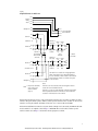
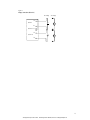
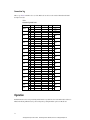
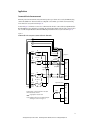
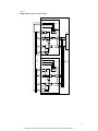
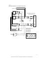
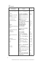
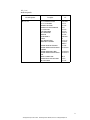
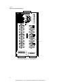
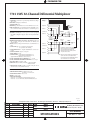
99 Washington Street Melrose, MA 02176 Phone 781-665-1400 Toll Free 1-800-517-8431 Visit us at www.TestEquipmentDepot.com Model 7701 User’s Guide PA-769 Rev. B / 8-03 The Model 7701 can be used with Keithley Models 2700, 2701, and 2750. All references to the Model 27xx apply to the Models 2700, 2701, and 2750. A GREATER MEASURE OF CONFIDENCE Test Equipment Depot - 800.517.8431 - 99 Washington Street Melrose, MA 02176 - TestEquipmentDepot.com Safety Precautions The following safety precautions should be observed before using this product and any associated instrumentation. Although some instruments and accessories would normally be used with non-hazardous voltages, there are situations where hazardous conditions may be present. This product is intended for use by qualified personnel who recognize shock hazards and are familiar with the safety precautions required to avoid possible injury. Read and follow all installation, operation, and maintenance information carefully before using the product. Refer to the manual for complete product specifications. If the product is used in a manner not specified, the protection provided by the product may be impaired. The types of product users are: Responsible body is the individual or group responsible for the use and maintenance of equipment, for ensuring that the equipment is operated within its specifications and operating limits, and for ensuring that operators are adequately trained. Operators use the product for its intended function. They must be trained in electrical safety procedures and proper use of the instrument. They must be protected from electric shock and contact with hazardous live circuits. Maintenance personnel perform routine procedures on the product to keep it operating properly, for example, setting the line voltage or replacing consumable materials. Maintenance procedures are described in the manual. The procedures explicitly state if the operator may perform them. Otherwise, they should be performed only by service personnel. Service personnel are trained to work on live circuits, and perform safe installations and repairs of products. Only properly trained service personnel may perform installation and service procedures. Keithley products are designed for use with electrical signals that are rated Measurement Category I and Measurement Category II, as described in the International Electrotechnical Commission (IEC) Standard IEC 60664. Most measurement, control, and data I/O signals are Measurement Category I and must not be directly connected to mains voltage or to voltage sources with high transient overvoltages. Measurement Category II connections require protection for high transient over-voltages often associated with local AC mains connections. Assume all measurement, control, and data I/O connections are for connection to Category I sources unless otherwise marked or described in the Manual. Exercise extreme caution when a shock hazard is present. Lethal voltage may be present on cable connector jacks or test fixtures. The American National Standards Institute (ANSI) states that a shock hazard exists when voltage levels greater than 30V RMS, 42.4V peak, or 60VDC are present. A good safety practice is to expect that hazardous voltage is present in any unknown circuit before measuring. Operators of this product must be protected from electric shock at all times. The responsible body must ensure that operators are prevented access and/or insulated from every connection point. In some cases, connections must be exposed to potential human contact. Product operators in these circumstances must be trained to protect themselves from the risk of electric shock. If the circuit is capable of operating at or above 1000 volts, no conductive part of the circuit may be exposed. Do not connect switching cards directly to unlimited power circuits. They are intended to be used with impedance limited sources. NEVER connect switching cards directly to AC mains. When connecting sources to switching cards, install protective devices to limit fault current and voltage to the card. Before operating an instrument, make sure the line cord is connected to a properly grounded power receptacle. Inspect the connecting cables, test leads, and jumpers for possible wear, cracks, or breaks before each use. When installing equipment where access to the main power cord is restricted, such as rack mounting, a separate main input power disconnect device must be provided, in close proximity to the equipment and within easy reach of the operator. For maximum safety, do not touch the product, test cables, or any other instruments while power is applied to the circuit under test. ALWAYS remove power from the entire test system and discharge any capacitors before: connecting or disconnecting cables or jumpers, installing or removing switching cards, or making internal changes, such as installing or removing jumpers. Do not touch any object that could provide a current path to the common side of the circuit under test or power line (earth) ground. Always make measurements with dry hands while standing on a dry, insulated surface capable of withstanding the voltage being measured. The instrument and accessories must be used in accordance with its specifications and operating instructions or the safety of the equipment may be impaired. Do not exceed the maximum signal levels of the instruments and accessories, as defined in the specifications and operating information, and as shown on the instrument or test fixture panels, or switching card. When fuses are used in a product, replace with same type and rating for continued protection against fire hazard. Chassis connections must only be used as shield connections for measuring circuits, NOT as safety earth ground connections. If you are using a test fixture, keep the lid closed while power is applied to the device under test. Safe operation requires the use of a lid interlock. Test Equipment Depot - 800.517.8431 - 99 Washington Street Melrose, MA 02176 - TestEquipmentDepot.com 5/03 If a screw is present, connect it to safety earth ground using the wire recommended in the user documentation. The ! symbol on an instrument indicates that the user should refer to the operating instructions located in the manual. The symbol on an instrument shows that it can source or measure 1000 volts or more, including the combined effect of normal and common mode voltages. Use standard safety precautions to avoid personal contact with these voltages. The frame. symbol indicates a connection terminal to the equipment The WARNING heading in a manual explains dangers that might result in personal injury or death. Always read the associated information very carefully before performing the indicated procedure. The CAUTION heading in a manual explains hazards that could damage the instrument. Such damage may invalidate the warranty. Instrumentation and accessories shall not be connected to humans. To maintain protection from electric shock and fire, replacement components in mains circuits, including the power transformer, test leads, and input jacks, must be purchased from Keithley Instruments. Standard fuses, with applicable national safety approvals, may be used if the rating and type are the same. Other components that are not safety related may be purchased from other suppliers as long as they are equivalent to the original component. (Note that selected parts should be purchased only through Keithley Instruments to maintain accuracy and functionality of the product.) If you are unsure about the applicability of a replacement component, call a Keithley Instruments office for information. To clean an instrument, use a damp cloth or mild, water based cleaner. Clean the exterior of the instrument only. Do not apply cleaner directly to the instrument or allow liquids to enter or spill on the instrument. Products that consist of a circuit board with no case or chassis (e.g., data acquisition board for installation into a computer) should never require cleaning if handled according to instructions. If the board becomes contaminated and operation is affected, the board should be returned to the factory for proper cleaning/servicing. Before performing any maintenance, disconnect the line cord and all test cables. Test Equipment Depot - 800.517.8431 - 99 Washington Street Melrose, MA 02176 - TestEquipmentDepot.com Keithley Instruments, Inc. 28775 Aurora Road Cleveland, Ohio 44139 (440) 248-0400 Fax: (440) 248-6168 www.keithley.com Model 7701 User’s Guide The information in this section is organized as follows: • Card configuration – schematic on page 2. • Connections and wiring on page 4. • Screw terminals on page 4. • D-shell connectors on page 6. • Wiring on page 7. • Typical connections on page 12. • Connection log on page 14. • Operation on page 14. • Channel assignments on page 15. • System channel operation on page 15. • Multiple channel operation on page 16. • Applications on page 17. • Service on page 25. • Performance verification on page 25. • Replaceable parts on page 25. • Specifications on page 30. PA-769 Rev. B / 8-03 Test Equipment Depot - 800.517.8431 - 99 Washington Street Melrose, MA 02176 - TestEquipmentDepot.com Introduction NOTE The 7701 module can be used with Keithley Models 2700, 2701, and 2750. All references to the Model 27xx apply to the Models 2700, 2701, and 2750. The Model 7701 is a 32-channel high speed differential multiplexer module and has the following features: • Voltage measurements (DC and AC). • Frequency and period measurements. • Normal ohms measurements: • 2-wire ohms to test up to 32 DUT. • 4-wire ohms to test up to 16 DUT. Normal Ω4 automatically pairs switches for four wire measurements — n + 16. • Common-side 4-wire ohms measurements – Configures the module to allow use of a common bus to perform 4-wire ohms measurements on up to 32 DUT. • Temperature applications (RTD or thermistor). • 50-pin female D-Shell connector (DB-50) for channels 1 through 24. • 25-pin female D-Shell connector (DB-25) for channels 25 through 32. • Screw terminals and supplied jumpers to access the DMM of the Model 27xx mainframe. WARNING NOTE The Model 7701 is configurable to be connected to the internal DMM via the supplied jumpers and the screw terminals. When connected to the internal DMM, all other modules must be derated to 150VDC or 150Vrms (212V peak) for AC waveforms. The Model 7701 is shipped from the factory with the screw terminal jumpers NOT installed. See “Screw terminals” to install the jumpers. WARNING Before operating the Model 27xx with an accessory card, verify that the card is properly installed and the mounting screws are tightly fastened. If the mounting screws are not properly connected, an electrical shock hazard may be present. Card configuration – schematic Figure 1 shows a simplified schematic diagram of the Model 7701 module. As shown, the Model 7701 has input channels that are grouped into two banks of sixteen channels (thirty-two channels total). A backplane isolation relay is provided for each bank. The first bank contains channels 1 through 16 while the second bank contains channels 17 through 32. Each input channel of the 32-channel multiplexer card is wired with separate inputs for HI/LO providing fully isolated inputs. As shown in Figure 1, all Model 7701 channels are isolated from the DMM of the Model 27xx by screw terminals. Supplied jumpers must be installed in the screw terminals to connect switching module channels to the DMM. For added flexibility, the Model 7701 is equipped with four extra screw terminals. These user-configurable screw terminals are hard-wired to the female DB-25 connector of the switching module. These screw terminals allow external input to bypass the switching module channels. Although the Model 7701 relays are the latching type (relays hold their state even after power has been removed), all relay states are set to open a few seconds after either a power cycle or an *RST command is issued. System channel operation (ROUT:CLOS command) is used to close measurement channels to connect a DUT to the DMM. With a 2-wire function selected (i.e., DCV), system channels 1 through 32 can be closed. When one of these channels is closed, channel 35 automatically closes to connect the channel to the DMM Input. 2 Test Equipment Depot - 800.517.8431 - 99 Washington Street Melrose, MA 02176 - TestEquipmentDepot.com Figure 1 Simplified schematic for Model 7701 P12 External P13 Wiring Access P24 P25 Multiplexer 1 Channel 1 HI P12 P13 User Configurable P24 Screw Terminals LO HI P25 LO Channel 35 (See Note) (Channels 215) HI Channel 16 LO Backplane Isolation Channel 33 2-Pole (Open) 4-Pole (Closed) (See Note) Channel 34 (See Note) HI Channel 17 LO Backplane Isolation (Channels 1831) HI Channel 32 LO Multiplexer 2 MUX 1 DMM HI HI HI Input LO MUX 1 DMM LO LO Screw Terminals MUX 2 HI DMM SHI To Model 27xx DMM HI Sense LO MUX 2 DMM LO SLO The Model 7701 is rated for low-voltage applications. When connecting the 7701 to the internal DMM via the screw terminals, all other modules in the mainframe must be derated to 150VDC or 150Vrms (212V peak) for AC waveforms. HI LO Notes: = Jumper to be installed by user to connect 7701 channels to DMM (Figure 3). Channels 3335 in this schematic refer to the designations used for control and not actual available channels. Channels 33, 34, and 35 can be individually controlled using multiple channel operation (ROUT:MULT commands). For more information, see Section 2 of the Model 27xx Users Manual. With a normal 4-wire function selected (i.e., Ω4), system channels 1 through 16 can be closed. These 16 channels are paired to channels 17 through 32 (channel 1 paired to channel 17, channel 2 paired to channel 18, and so on). When one of these system channels is closed, its paired channel, and channels 33 and 34 also close to connect the DUT to the DMM. With common-side (CSID) 4-wire ohms selected, system channels 1 through 32 can be measured by the DMM. For this ohms mode, the module is to be configured as shown in Figure 12. With CSID ohms selected, channel 33 remains open and channel 35 remains closed. In Figure 12, the bold lines show the signal path to test DUT1. 3 Test Equipment Depot - 800.517.8431 - 99 Washington Street Melrose, MA 02176 - TestEquipmentDepot.com Dual independent multiplexers WARNING Multiple channel operation should only be performed by experienced test engineers who recognize the dangers associated with multiple channel closures. Multiple channel operation (ROUT:MULT:CLOS command) allows individual control of switching module channels. Multiple channel operation allows the switching module to be configured as two independent multiplexers. The Model 7701 is normally used as a single 1 × 32 multiplexer, but it can also be configured as two 1 × 16 multiplexers. In Figure 1, the open position of channel 33 is shown. When channel 33 is closed, Multiplexer 1 (channels 1 through 16) are isolated from Multiplexer 2 (channels 16 through 32). For the dual multiplexer configuration, only Multiplexer 1 channels can be internally connected to the DMM of the Model 27xx. Closing channel 35 allows channels 1 through 16 to be measured by the DMM. When using the dual multiplexer configuration, Multiplexer 2 must be isolated from the sense terminals of the DMM. This can be done by keeping channel 34 open, or by not installing the screw terminal jumpers to DMM Sense. Connections and wiring WARNING The following information is intended for qualified service personnel. Do not make switching module connections unless qualified to do so. To prevent electric shock that could result in serious injury or death, adhere to the following safety precautions: • Before removing or installing the switching module in the mainframe, make sure the mainframe is turned off and disconnected from line power. • Before making or breaking connections, make sure power is removed from all external circuitry. • Do not connect signals that may exceed the maximum specifications of the Model 7701. Specifications are provided at the end of this section. WARNING The Model 7701 is configurable to be connected to the internal DMM via the supplied jumpers and the screw terminals. When connected to the internal DMM, all other modules must be derated to 150VDC or 150Vrms (212V peak) for AC waveforms. Screw terminals The screw terminals of the Model 7701 are shown in Figure 2. As shown, screw terminals are provided to connect the switching module channels to the DMM. User-configurable screw terminals are also provided to allow external input to bypass the switching module channels. Four jumpers are supplied with the Model 7701 for use with the screw terminals. As shown in Figure 2, the Model 7701 is shipped with the jumpers not installed. With the jumpers not installed, all input to the Model 7701 is electrically isolated from the DMM. 4 Test Equipment Depot - 800.517.8431 - 99 Washington Street Melrose, MA 02176 - TestEquipmentDepot.com Figure 2 Model 7701 screw terminals Screw Terminals to Connect 7701 Channels to DMM DMM HI User-Configurable Screw Terminals MUX 1 HI P12 P13 P24 P25 MUX 2 HI DMM SHI DMM SLO MUX 2 LO MUX 1 LO DMM LO DMM HI MUX 1 HI P12 P13 P24 P25 MUX 2 HI DMM SHI DMM SLO MUX 2 LO MUX 1 LO DMM LO 5 Test Equipment Depot - 800.517.8431 - 99 Washington Street Melrose, MA 02176 - TestEquipmentDepot.com Connecting Model 7701 channels to DMM Perform the following steps to internally connect the channels of the Model 7701 to the DMM of the Model 27xx: 1. Remove the top cover of the Model 7701. It is secured to the module case by a single screw. 2. Install the four supplied #22 AWG jumpers in the screw terminals as shown in Figure 3. Position the jumpers to allow clearance for the top cover and make sure the jumper wires do not come in contact with each other or other electrical conductors. 3. Replace the top cover. Figure 3 Jumper installation to connect 7701 channels to DMM DMM HI A MUX 1 HI Jumper A Connects HI terminals of Multiplexer 1 channels (1 through 16) to DMM Input HI. MUX 2 HI B DMM SHI Jumper B Connects HI terminals of Multiplexer 2 channels (17 through 32) to DMM Sense HI. Jumper C Connects LO terminals of Multiplexer 2 channels (17 through 32) to DMM Sense LO. Jumper D Connects LO terminals of Multiplexer 1 channels (1 through 16) to DMM Input LO. DMM SLO C MUX 2 LO MUX 1 LO D DMM LO Jumper (1 of 4) D-shell connectors Figure 4 shows the pin numbers for the Model 7701 rear panel connectors. The 50-pin D-shell is used to access channels 1 through 24, and Multiplexer 1 terminals. The 25-pin D-shell is used to access channels 25 through 32, and Multiplexer 2 terminals. The user-configurable screw terminals are also accessed at the 25-pin D-shell. Terminal identification for the female connector pins is provided in Table 1. Figure 4 Rear view – Model 7701 pinouts 50-Pin D-Shell Connector (Female) 17 33 25-Pin D-Shell Connector (Female) 1 13 1 18 50 34 25 14 6 Test Equipment Depot - 800.517.8431 - 99 Washington Street Melrose, MA 02176 - TestEquipmentDepot.com Table 1 D-shell pin identification 50-pin D-shell (DB-50) Pin 1 2 3 4 5 6 7 8 9 10 7701 Terminal Ch 1 Hi Ch 2 Lo Ch 4 Hi Ch 5 Lo Ch 7 Hi Ch 8 Lo Ch 10 Hi Ch 11 Lo Ch 13 Hi Ch 14 Lo Pin 11 12 13 14 15 16 17 18 19 20 7701 Terminal Ch 16 Hi Ch 17 Lo Ch 19 Hi Ch 20 Lo Ch 22 Hi Ch 23 Lo Mux 1 Hi Ch 2 Hi Ch 3 Lo Ch 5 Hi Pin 21 22 23 24 25 26 27 28 29 30 7701 Terminal Ch 6 Lo Ch 8 Hi Ch 9 Lo Ch 11 Hi Ch 12 Lo Ch 14 Hi Ch 15 Lo Ch 17 Hi Ch 18 Lo Ch 20 Hi Pin 31 32 33 34 35 36 37 38 39 40 7701 Terminal Ch 21 Lo Ch 23 Hi Ch 24 Lo Ch 1 Lo Ch 3 Hi Ch 4 Lo Ch 6 Hi Ch 7 Lo Ch 9 Hi Ch 10 Lo Pin 41 42 43 44 45 46 47 48 49 50 7701 Terminal Ch 12 Hi Ch 13 Lo Ch 15 Hi Ch 16 Lo Ch 18 Hi Ch 19 Lo Ch 21 Hi Ch 22 Lo Ch 24 Hi Mux 1 Lo 25-pin D-shell (DB-25) Pin 1 2 3 4 5 6 7701 Terminal Ch 25 Hi Ch 26 Hi Ch 27 Hi Ch 28 Hi Ch 29 Hi Ch 30 Hi Pin 7 8 9 10, 11 12 13 7701 Terminal Ch 31 Hi Ch 32 Hi Mux 2 Hi — P12 P13 Pin 14 15 16 17 18 19 7701 Terminal Ch 25 Lo Ch 26 Lo Ch 27 Lo Ch 28 Lo Ch 29 Lo Ch 30 Lo Pin 20 21 22 23 24 25 7701 Terminal Ch 31 Lo Ch 32 Lo Mux 2 Lo — P24 P25 Wiring NOTE The Model 7701 is shipped with plastic connector covers installed on the D-shell connectors. Each cover is secured to the connector by two screws. After removing a connector cover, retain it and the screws for future use. Any unused D-shell connector must have the connector cover installed. The Model 7701 is supplied with one 50-pin male IDC ribbon cable connector, and one 25-pin male IDC ribbon cable connector. These ribbon cable connectors mate to the D-shell connectors of the switching module. WARNING When using IDC ribbon cable connections, DO NOT exceed 42V anywhere in the test system or at the front panel inputs of the Model 27xx. For higher voltage applications, use larger wire (up to #20 AWG) and solder cup D-shell connectors. There are two connector kits that have connectors that can be used with the Model 7701: • Model 7790 ribbon cable adapter kit — Contains one female DB-50, one male DB-50 and one male DB-25 IDC ribbon cable connectors. The two male IDC connectors mate to the D-shell connectors on the Model 7701. • Model 7789 50/25-pin solder cup connector kit — Contains one male DB-50 and one male DB-25 solder cup connectors. These connectors mate to the D-shell connectors on the Model 7701. 7 Test Equipment Depot - 800.517.8431 - 99 Washington Street Melrose, MA 02176 - TestEquipmentDepot.com IDC ribbon cable connections Connect an appropriate length of 50-conductor IDC ribbon cable to a 50-pin male D-shell IDC connector, and connect an appropriate length of 25-conductor IDC ribbon cable to a 25-pin male D-shell IDC connector. Table 2 and Figure 5 provides terminal identification for the 50-pin ribbon cable connections. Table 3 and Figure 6 provides terminal identification for the 25-pin ribbon cable connections. The connectors of the prepared ribbon cable assemblies mate to the 50- and 25-pin D-shell connectors of the Model 7701 (Figure 7). Make sure an unused D-shell connector has the connector cover installed. Table 2 Terminal identification for 50-conductor IDC ribbon cable and 7701 DB-50 connector Ribbon Cable*: Conductor Color 1 2 3 4 5 6 7 8 9 10 11 12 13 14 15 16 17 18 19 20 21 22 23 24 25 Brown Red Orange Yellow Green Blue Violet Grey White Black Brown Red Orange Yellow Green Blue Violet Grey White Black Brown Red Orange Yellow Green 7701 DB-50 Terminal Pin # Ch 1 Hi Ch 1 Lo Ch 2 Hi Ch 2 Lo Ch 3 Hi Ch 3 Lo Ch 4 Hi Ch 4 Lo Ch 5 Hi Ch 5 Lo Ch 6 Hi Ch 6 Lo Ch 7 Hi Ch 7 Lo Ch 8 Hi Ch 8 Lo Ch 9 Hi Ch 9 Lo Ch 10 Hi Ch 10 Lo Ch 11 Hi Ch 11 Lo Ch 12 Hi Ch 12 Lo Ch 13 Hi 1 34 18 2 35 19 3 36 20 4 37 21 5 38 22 6 39 23 7 40 24 8 41 25 9 Ribbon Cable*: Conductor Color 26 27 28 29 30 31 32 33 34 35 36 37 38 39 40 41 42 43 44 45 46 47 48 49 50 Blue Violet Grey White Black Brown Red Orange Yellow Green Blue Violet Grey White Black Brown Red Orange Yellow Green Blue Violet Grey White Black 7701 DB-50 Terminal Pin # Ch 13 Lo Ch 14 Hi Ch 14 Lo Ch 15 Hi Ch 15 Lo Ch 16 Hi Ch 16 Lo Ch 17 Hi Ch 17 Lo Ch 18 Hi Ch 18 Lo Ch 19 Hi Ch 19 Lo Ch 20 Hi Ch 20 Lo Ch 21 Hi Ch 21 Lo Ch 22 Hi Ch 22 Lo Ch 23 Hi Ch 23 Lo Ch 24 Hi Ch 24 Lo Mux 1 Hi Mux 1 Lo 42 26 10 43 27 11 44 28 12 45 29 13 46 30 14 47 31 15 48 32 16 49 33 17 50 *50-conductor IDC ribbon cable is available from Keithley, Part #15020. 8 Test Equipment Depot - 800.517.8431 - 99 Washington Street Melrose, MA 02176 - TestEquipmentDepot.com Figure 5 50-conductor ribbon cable terminal identification 50-Pin D-Shell Male IDC IDC Ribbon Cable — 50-Conductor 1 Brown 3 Orange 2 Red 4 Yellow 5 Green 6 Blue 7 Violet 8 Grey 9 White 10 Black 11 Brown 13 Orange 12 Red 14 Yellow 15 Green 16 Blue 17 Violet 18 Grey 19 White 21 Brown 23 Orange 20 Black 22 Red 24 Yellow 25 Green 26 Blue 27 Violet 28 Grey 29 White 31 Brown 33 Orange 30 Black 32 Red 34 Yellow 35 Green 37 Violet 36 Blue 38 Grey 39 White 41 Brown 43 Orange 40 Black 42 Red 44 Yellow 45 Green 46 Blue 47 Violet 48 Grey 49 White 50 Black HI LO Ch 1 HI Ch 2 LO HI LO Ch 3 HI LO Ch 4 HI LO Ch 5 HI Ch 6 LO HI LO Ch 7 HI LO Ch 8 HI LO Ch 9 HI Ch 10 LO HI Ch 11 LO HI Ch 12 LO HI Ch 13 LO HI LO Ch 14 HI Ch 15 LO HI Ch 16 LO HI Ch 17 LO HI LO Ch 18 HI Ch 19 LO HI LO Ch 20 HI LO Ch 21 HI Ch 22 LO HI Ch 23 LO HI Ch 24 LO HI Multiplexer LO 1 9 Test Equipment Depot - 800.517.8431 - 99 Washington Street Melrose, MA 02176 - TestEquipmentDepot.com Table 3 Terminal identification for 25-conductor IDC ribbon cable and 7701 DB-25 connector Ribbon Cable*: Conductor Color 7701 DB-25 Terminal Pin # Ribbon Cable*: Conductor Color 7701 DB-25 Terminal Pin # 1 2 3 4 5 6 7 8 9 10 11 12 13 Ch 25 Hi Ch 25 Lo Ch 26 Hi Ch 26 Lo Ch 27 Hi Ch 27 Lo Ch 28 Hi Ch 28 Lo Ch 29 Hi Ch 29 Lo Ch 30 Hi Ch 30 Lo Ch 31 Hi 14 15 16 17 18 19 20 21 22 23 24 25 Ch 31 Lo Ch 32 Hi Ch 32 Lo Mux 2 Hi Mux 2 Lo — — — P24 P12 P25 P13 Brown Red Orange Yellow Green Blue Violet Grey White Black Brown Red Orange 1 14 2 15 3 16 4 17 5 18 6 19 7 Yellow Green Blue Violet Grey White Black Brown Red Orange Yellow Green 20 8 21 9 22 — — — 24 12 25 13 *25-conductor IDC ribbon cable is available from Keithley, Part #15025. Figure 6 25-conductor ribbon cable terminal identification 25-Pin D-Shell Male IDC IDC Ribbon Cable — 25-Conductor 1 Brown 3 Orange 2 Red 4 Yellow 5 Green 6 Blue 7 Violet 8 Grey 9 White 10 Black 11 Brown 12 Red 13 Orange 14 Yellow 15 Green 16 Blue 17 Violet 18 Grey HI LO Channel 25 HI Channel 26 LO HI Channel 27 LO HI Channel 28 LO HI Channel 29 LO HI Channel 30 LO HI Channel 31 LO HI Channel 32 LO HI Multiplexer 2 LO 19 White 20 Black 21 Brown 22 Red 23 Orange 24 Yellow 25 Green P24 P12 P25 P13 10 Test Equipment Depot - 800.517.8431 - 99 Washington Street Melrose, MA 02176 - TestEquipmentDepot.com Figure 7 Connecting ribbon cable assembly KEITHLEY CONNECTOR COVER Warning: When using ribbon cable, DO NOT exceed 42 volts anywhere in the test system or at the front panel inputs of the Model 27xx. Install plastic cover over unused connector using two #4-40 screws. Solder cup cable connections Make all connections to D-shell male solder cup connectors using the correct wire size up to 20 AWG. Terminal identification for the 50-pin D-shell connector is provided in Table 1 and Table 2. Terminal identification for the 25-pin D-shell connector is provided in Table 1 and Table 3. Make sure to add supplementary insulation around the harness for voltages above 42V peak (Figure 8). WARNING All solder cup wiring must be rated for the maximum voltage in the system. For example, if 150V is applied to the front terminals of the DMM, All matrix module wiring must be rated for 150V. A connector cover must be installed on an unused D-shell connector. If the connector is left open, an electrical shock hazard may be present. Figure 8 Connecting solder cup cable assembly KEITHLEY CONNECTOR COVER Install plastic cover over unused connector using two #4-40 screws. Supplementary Insulation 11 Test Equipment Depot - 800.517.8431 - 99 Washington Street Melrose, MA 02176 - TestEquipmentDepot.com Typical connections The following examples show typical wiring connections for the following types of measurements: • Ω2-Wire and thermistor connections, Figure 9. • Ω4-Wire and RTD connections, Figure 10. • Voltage connections (AC or DC), Figure 11. Figure 9 Ω2-Wire and thermistor connections HI Column 1 LO (Columns 2 31) Resistors or Thermistors HI Column 32 LO Figure 10 Ω4-Wire and RTD connections HI Resistor or 4-Wire RTD Column 1 LO (Columns 2 15) HI Resistor or 4-Wire RTD Column 16 LO HI Column 17 LO (Columns 18 31) HI Column 32 LO 12 Test Equipment Depot - 800.517.8431 - 99 Washington Street Melrose, MA 02176 - TestEquipmentDepot.com Figure 11 Voltage connections (DC or AC) DC Voltage AC Voltage HI + Column 1 LO (Columns 2 31) HI + Column 32 LO 13 Test Equipment Depot - 800.517.8431 - 99 Washington Street Melrose, MA 02176 - TestEquipmentDepot.com Connection log Make a copy of Table 4 and affix it to the cover of the Model 7701. Use this to record connection information and channel descriptions as needed. Table 4 Connection log Model 7701 Channel MUX 1 MUX 2 CH1 CH2 CH3 CH4 CH5 CH6 CH7 CH8 CH9 CH10 CH11 CH12 CH13 CH14 CH15 CH16 Color H L H L H L H L H L H L H L H L H L H L H L H L H L H L H L H L H L H L Description Description Color Channel P12 P13 P24 P25 H L H L H L H L H L H L H L H L H L H L H L H L H L H L H L H L CH17 CH18 CH19 CH20 CH21 CH22 CH23 CH24 CH25 CH26 CH27 CH28 CH29 CH30 CH31 CH32 Operation Detailed information to close and open switching module channels are provided in Section 2 of the Model 2700 or 2750 User’s Manual. The following summarizes basic operation, and provides operating information specific to the Model 7701. 14 Test Equipment Depot - 800.517.8431 - 99 Washington Street Melrose, MA 02176 - TestEquipmentDepot.com Channel assignments The Model 2700 has two slots for switching modules and the Model 2750 has five slots. To control the appropriate switching module, the slot number must be included with the switching module channel number when you specify a channel. The channel assignment is formatted as follows: SCH where: S is the slot number CH is the channel number Examples: 101 = Slot 1, Channel 1 210 = Slot 2, Channel 10 506 = Slot 5, Channel 6 (Model 2750) NOTE For remote operation, the 3-digit channel assignment is included in the channel list parameter for the commands. System channel operation System channel operation is used to connect measurement channels to the Model 27xx DMM. With 2-wire function selected, system channels 1 through 32 can be closed. When one of these channels is closed, channel 35 automatically closes to connect the measurement channel to the DMM Input. With a 4-wire function selected, system channels 1 through 16 can be closed. When one of these channels is closed, its paired channel closes, and the backplane relays for sense and input (channels 34 and 35) also close. For a 4-wire function, channels are paired as follows: CH1 and CH17 CH2 and CH18 CH3 and CH19 CH4 and CH20 CH5 and CH21 CH6 and CH22 CH7 and CH23 CH8 and CH24 CH9 and CH25 CH10 and CH26 CH11 and CH27 CH12 and CH28 CH13 and CH29 CH14 and CH30 CH15 and CH31 CH16 and CH32 System channel operation for the Model 7701 is summarized as follows: • The / keys on the Model 27xx DMM can be used to close a system channel. • The CLOSE key can be used to close a system channel. For the Model 2701/2750 and later versions of the Model 2700, use the SINGLE option of the CLOSE key. • Use the OPEN key to open all channels in the test system. For the Model 2701/2750 and later versions of the Model 2700, use the ALL option of the OPEN key. • For remote operation, the following commands are used for system channel operation: ROUT:CLOS <clist> ROUT:CLOS? ROUT:CLOS:STAT? <clist> ROUT:OPEN:ALL Close specified system channel. Returns the closed system channel. Query closed channels in list (1 = closed). Open all channels. Common-side (CSID) 4-wire ohms The Model 7701 can be configured to use a common bus to perform 4-wire ohms measurements on up to 32 DUT. Details of CSID operation is provided in the application for Common-side 4-wire ohms measurements on page 17. 15 Test Equipment Depot - 800.517.8431 - 99 Washington Street Melrose, MA 02176 - TestEquipmentDepot.com Amps measurements The 7701 module does not support amps measurements. System channel operation cannot be used to close channels while an amps function (DCI or ICI) is selected. If an amps function (DCI or ACI) is selected and you attempt to close a system channel, the message “NO AMPS CHAN” will be displayed briefly. For remote programming, error -222 (Parameter data out of range) is generated. Example: SYST:PRES SENS:FUNC ‘CURR:DC’ ROUT:CLOS (@101) ‘ Restores system preset defaults. ‘ Selects DCI function. ‘ Attempts to close system channel 101 – Generates error -222. If a system channel is already closed and you attempt to select the DCI or ACI function, the message “INVALID FUNC” will be displayed briefly. For remote programming, error -221 (Settings conflict) is generated. Example: SYST:PRES ROUT:CLOS (@101) SENS:FUNC ‘CURR:DC’ ‘ Restores system preset defaults. ‘ Close system channel 101. ‘ Attempts to select DCI function – Generates error -221. Making amps measurements – In order to perform amps measurements, you must use the front panel inputs of the 27xx mainframe. You can still use the 7701 module for other aspects of the test (such as controlling a bias supply for DUT), but you must use multiple channel operation to close channels. Example: NOTE In order to use the front panel inputs, make sure the INPUT switch is in the out (F) position. SYST:PRES ROUT:MULT:CLOS (@101) SENS:FUNC ‘CURR:DC’ ‘ Restores system preset defaults. ‘ Closes channel 101. ‘ Selects DCI function – Legal operation. Multiple channel operation WARNING Multiple channel operation should only be performed by experienced test engineers who recognize the dangers associated with multiple channel closures. Multiple channel operation provides independent control of switching module channels (1 through 35). When you close or open a multiple channel, only the specified channel (or channels) will close or open. Other closed or open channels are not affected. Multiple channel operation for the Model 7701 is summarized as follows: • For earlier versions of the Model 2700, multiple channel operation is not available from the front panel (remote operation only). • For the Model 2701/2750 and later versions of the Model 2700, the MULTI option of the CLOSE key can be used to close a channel. • For the Model 2701/2750 and later versions of the Model 2700, the MULTI option of the OPEN key can be used to open a channel. The ALL option of the OPEN key opens all channels. ROUT:MULT:CLOS <clist> ROUT:MULT:OPEN <clist> ROUT:MULT:CLOS? ROUT:MULT:CLOS:STAT? <clist> Close specified channels (unlisted channels not affected). Open specified channels (unlisted channels not affected). Returns list of all closed channels. Query closed channels in list (1 = closed). You can also use the following command to open all channels: ROUT:OPEN:ALL Open all channels. 16 Test Equipment Depot - 800.517.8431 - 99 Washington Street Melrose, MA 02176 - TestEquipmentDepot.com Applications Common-side 4-wire ohms measurements When using 4-wire ohms measurements and system channel operation, up to 16 DUT can be tested by the DMM. By using common-side (CSID) 4-wire ohms mode and the user configurable screw terminals, up to 32 DUT can be measured using 4-wire ohms. Such a test system is shown in Figure 12. As shown in Figure 12, all 32 DUT are connected to a common metal bus. The bus is connected directly to Input HI and Sense HI of the DMM via the user-configurable screw terminals. The 32 measurement channels can then be used to connect the other side of each DUT to Input LO and Sense LO of the DMM. Jumper installation for this test system is shown in Figure 13. Figure 12 Common-side 4-wire test system (common-side 4-wire ohms mode) P12 P13 P24 P25 Input HI DUT1 DUT16 Sense HI HI Ch 1 LO (Ch 215) HI Jumper B Jumper C Sense LO Ch 35 Ch 16 Input LO LO Jumper D Ch 33 (Open) DUT17 HI Ch 17 Common-Side Bus HI Ch 32 DMM Equivalent Circuit HI Input LO LO System channel 1 closed to perform 4-wire CSID ohms measurement on DUTI. HI Input LO HI Sense LO Ch 34 LO (Ch 1831) DUT32 Jumper A DUT DMM = Signal path to measure DUT1 Note: Installation of the four screw terminal jumpers (A through D) is shown in Figure 13. HI Sense LO 17 Test Equipment Depot - 800.517.8431 - 99 Washington Street Melrose, MA 02176 - TestEquipmentDepot.com With the 4-wire common-side ohms mode selected, channels 33 and 35 are automatically controlled as follows when a system input channel (1 through 32) is closed. • Channel 33 is forced open to connect Multiplexer 1 (channels 1 through 16) to Multiplexer 2 (channels 17 through 32). • Channel 35 is forced closed to connect an input channel (1 through 32) to the DMM Input. Closing input channel 1 also closes channel 35 to connect DUT1 to the DMM input. All other input channels will open (see Figure 12). Closing channel 2 also closes channel 35 to connect DUT2 to the DMM. Again, all other channels will open. The other 30 input channels are controlled in a similar manner. Closing an input channel also closes channel 35 to connect the DUT to the DMM. All other channels will open. Selecting 4-wire ohms mode There are two 4-wire ohms modes: NORM (normal) and CSID (common-side). For this application use the following procedure to select the CSID mode. The 4-wire ohms mode can be selected using the following key-press sequence: 1. Press SHIFT and then press CARD. 2. Select CONFIG. 3. Select slot that has the 7701 (i.e., SLOT1: 7701). 4. Select 4W MODE: NORM (normal) or CSID (common-side). NOTE Changing the 4-wire ohms mode opens all channels for all modules in the mainframe. For remote programming, the following commands are valid with a 7701 module installed: SYSTem:FRESistance:TYPEx, NORMal SYSTem:FRESistance:TYPEx, CSIDe SYSTem:FRESistance:TYPEx? ‘ Select normal 4W mode. ‘ Select common-side 4W mode. ‘ Query 4W mode. Where the x in TYPEx is the slot number for the 7701 module. NOTE For the Model 2700, the SYST:FRES:TYPEx command is only supported in units with firmware revision B03.1 or later. The command is supported for all Model 2701 and 2750 units. Figure 13 Jumper installation for common-side 4-wire ohms test system Jumper (1 of 4) Jumper B Jumper C Jumper D Connects the DUT common-side bus to DMM Input HI. Connects the DUT common-side bus to DMM Sense HI. Connects the DUT to DMM Sense LO through the switching channels. Connects DUT to DMM Input LO through the switching channels. Note: These screw teminal jumper connections are required for the common-side 4-wire ohms test system shown in Figure 12. A P12 P13 P24 P25 Jumper A DMM HI MUX 1 HI MUX 2 HI C DMM SHI B DMM SLO MUX 2 LO MUX 1 LO D DMM LO 18 Test Equipment Depot - 800.517.8431 - 99 Washington Street Melrose, MA 02176 - TestEquipmentDepot.com Test procedure: NOTE The following test procedure assumes a Model 7701 switching module installed in slot 1 of the mainframe. 1. Open all channels. Front panel operation: Remote programming: Press OPEN > Display ALL > Press OPEN ROUT:OPEN:ALL 2. Select Ω4 function. Front panel operation: Remote programming: Press Ω4 key SENS:FUNC ‘FRES’ 3. Select the common-side (CSID) 4-wire ohms mode. Front panel operation: Press SHIFT > Press CARD > Select CONFIG > Select SLOT1: 7701 > Select 4W MODE: CSID Remote programming: SYST:FRES:TYPE1 CSID 4. Close channel 1 to test DUT1. Front panel operation: Remote programming: 5. Measure DUT #1. Front panel operation: Remote programming: Press the key to close the first channel (Ch. 1) ROUT:CLOS (@101) Take reading from display DATA? (for continuous triggering mode) READ? (for one-shot triggering mode) 6. Close next channel to test DUT. Front panel operation: Remote programming: 7. Measure DUT. Front panel operation: Remote programming: Press the key to close the next channel (Ch. 2) ROUT:CLOS (@102) Take reading from display DATA? (for continuous triggering mode) READ? (for one-shot triggering mode) 8. In general, repeat steps 6 and 7 to test DUT3 through DUT32. That is, close the DUT input channel and take a measurement. 9. After all DUT is tested, repeat step 1 to open all channels. 10. Return the Model 27xx to the normal ohms mode. Front panel operation: Press SHIFT > Press CARD > Select CONFIG > Select SLOT1: 7701 > Select 4W MODE: NORM Remote programming: SYST:FRES:TYPE1 NORM 19 Test Equipment Depot - 800.517.8431 - 99 Washington Street Melrose, MA 02176 - TestEquipmentDepot.com Multiple module system Figure 12 shows a one-card test system to perform common-side ohms measurements on up to 32 DUT. The test system can be expanded to test more DUT by adding one or more modules: • Models 2700 and 2701 – Adding a second Model 7701 to the test system allows up to 64 DUT to be tested. • Model 2750 – Use up to five Model 7701s to test up to 160 DUT. When adding a Model 7701 module to a common-side ohms test system, you must wire the card properly to minimize path resistance, especially for low-ohms measurements. Figure 14 shows how to properly wire a multiple card system for commonside ohms measurements. This connection scheme will minimize signal path resistance through the backplane connections of the modules. Notice that for the second module (slot 2), the P12 and P13 terminals are not used. Only the P12 and P13 terminals of the first module are to be connected. It is best to use one common-side bus for all DUT. However, if more than one bus must be used, connect them together using a bus jumper (as shown in Figure 14). 20 Test Equipment Depot - 800.517.8431 - 99 Washington Street Melrose, MA 02176 - TestEquipmentDepot.com Figure 14 Multiple module test system (common-side ohms) Keithley 27xx Mainframe Keithley 7701 Switching Module P12 P13 SLOT 1 P24 P25 Input HI DUT1 Sense HI HI Ch 1 DUT16 DMM LO (Ch 2–15) HI Input HI LO Sense LO Ch 35 Ch 16 Input LO LO Ch 33 (Open) DUT17 Sense HI LO HI Ch 17 Ch 34 LO (Ch 18–31) DUT32 HI Ch 32 LO Common-Side Bus Keithley 7701 Switching Module Bus Jumper P12 P13 27xx Backplane SLOT 2 P24 P25 Input HI DUT33 Sense HI HI Ch 1 DUT48 LO (Ch 2–15) HI Sense LO Ch 35 Ch 16 Input LO LO Ch 33 (Open) DUT49 HI Ch 17 LO (Ch 18–31) DUT64 HI Ch 34 To other 2750 slots Ch 32 Common-Side Bus LO 21 Test Equipment Depot - 800.517.8431 - 99 Washington Street Melrose, MA 02176 - TestEquipmentDepot.com Biasing and measuring DUT (dual multiplexing) WARNING Multiple channel operation is required for the following application. Multiple channel operation should only be performed by experienced test engineers who recognize the dangers associated with multiple channel closures. This application demonstrates how to use the Model 7701 as a dual multiplexer to bias and measure 16 DUT. An external source powers DUT, while the DMM of the Model 27xx measures the output of the DUT. To prevent overloading of the external source, each DUT is powered (and measured) separately. Figure 15 shows the connections for this application. The external source is connected to the Multiplexer 2 terminals of the switching module, and DUT is connected to channels 1 through 16. Channels 17 through 32 are used to connect external power to each DUT. For this application, channels 33, 34, and 35 are to be controlled as follows: • Closing channel 33 isolates the input measurement channels 1 through 16 (Multiplexer 1) from the external source channels 11 through 20 (Multiplexer 2). It also connects the DUT to the external source. This channel must remain closed while testing DUT. • Opening channel 34 isolates the external source from the backplane of the Model 2750. This channel must remain open while testing DUT. • Closing channel 35 connects an input channel (1 through 16) to the DMM. This channel must remain closed while testing DUT. In Figure 15, channels 1 and 17 are closed to test DUT 1. The test for the other DUTs is similar except that different source and measure channels are closed. Closed channels for each DUT test are listed as follows: Tested Device DUT 1 DUT 2 DUT 3 DUT 4 DUT 5 DUT 6 DUT 7 DUT 8 Closed Channels 1, 17, 33, and 35 2, 18, 33, and 35 3, 19, 33, and 35 4, 20, 33, and 35 5, 21, 33, and 35 6, 22, 33, and 35 7, 23, 33, and 35 8, 24, 33, and 35 Tested Device DUT 9 DUT 10 DUT 11 DUT 12 DUT 13 DUT 14 DUT 15 DUT 16 Closed Channels 9, 25, 33, and 35 10, 26, 33, and 35 11, 27, 33, and 35 12, 28, 33, and 35 13, 29, 33, and 35 14, 30, 33, and 35 15, 31, 33, and 35 16, 32, 33, and 35 22 Test Equipment Depot - 800.517.8431 - 99 Washington Street Melrose, MA 02176 - TestEquipmentDepot.com Figure 15 Biasing and measuring DUT test system (multiple channel operation) HI Multiplexer 1 LO HI DUT Ch 1 Note: Installation of the four screw terminal jumpers is shown. LO (Channels 2–15) HI DUT HI Input LO Ch 35 Ch 16 LO Jumper (1 of 4) Ch 33 (Closed) HI Ch 17 HI Sense LO Ch 34 LO (Channels 18–31) HI Ch 32 LO External Source HI Multiplexer 2 LO DMM Multiple Channel Operation: Open all Channels Close Channel 133 Close Channel 135 Close Channel 101 Close Channel 111 External DUT 1 DMM Equivalent Circuit 23 Test Equipment Depot - 800.517.8431 - 99 Washington Street Melrose, MA 02176 - TestEquipmentDepot.com Test procedure: NOTE The following test procedure assumes a Model 7701 switching module installed in slot 1 of the mainframe. Multiple channel operation from the front panel is not available for early versions of the Model 2700. 1. Open all channels. Front panel operation: Remote programming: Press OPEN > Display ALL > Press OPEN ROUT:OPEN:ALL 2. Close channel 33 to isolate measure channels (1 through 16) from source channels (17 through 32). Front panel operation: Press CLOSE > Select MULTI > Key in 133 > Press ENTER Remote programming: ROUT:MULT:CLOS (@133) 3. Close channel 35 to connect measure channels (1 through 16) to DMM Input. Front panel operation: Press CLOSE > Select MULTI > Key in 135 > Press ENTER Remote programming: ROUT:MULT:CLOS (@135) 4. Close channel 1 to connect DUT 1 to the DMM. Front panel operation: Press CLOSE > Select MULTI > Key in 101 > Press ENTER Remote programming: ROUT:MULT:CLOS (@101) 5. Close channel 17 to connect DUT 1 to the external source. Front panel operation: Press CLOSE > Select MULTI > Key in 117 > Press ENTER Remote programming: ROUT:MULT:CLOS (@117) 6. Measure DUT 1. Front panel operation: Remote programming: Take reading from display DATA? (for continuous triggering mode) READ? (for one-shot triggering mode) 7. Open channels 1 and 17 to disconnect the DMM and external source from DUT 1. Front panel operation: Press OPEN > Select MULTI > Key in 101 > Press ENTER Press OPEN > Select MULTI > Key in 117 > Press ENTER Remote programming: ROUT:MULT:OPEN (@101,117) 8. In general, repeat steps 4 through 7 to test DUT 2 through DUT 16. That is, close the channels to connect the DUT to the DMM and external source, take a measurement, and then open the channels to disconnect the DUT from the DMM and external source. 9. After all DUT is tested, repeat step 1 to open all channels. 24 Test Equipment Depot - 800.517.8431 - 99 Washington Street Melrose, MA 02176 - TestEquipmentDepot.com Service Service for the Model 7701 includes a procedure to verify performance, and provides replaceable parts information. WARNING All service information is intended only for qualified service personnel. Do not attempt to service the Model 7701 unless you are qualified to do so. Performance verification Use the performance verification procedure for the Model 7701. This procedure is provided in PA-775 of this manual. Replaceable parts This section contains replacement parts information and the component layout drawing for the Model 7701. Parts list Replaceable parts for the Model 7701 are listed in Table 5. Ordering information To place an order, or to obtain information concerning replacement parts, contact your Keithley representative or the factory (see back cover for addresses). When ordering parts, be sure to include the following information: • • • • • Card model number (Model 7701). Card serial number. Part description. Component designation (if applicable). Keithley part number. Factory service If the instrument is to be returned to Keithley Instruments for repair, perform the following: • Call the Repair Department at 1-888-KEITHLEY for a Return Material Authorization (RMA) number. • Carefully pack the instrument in the original packing carton. • Write ATTENTION REPAIR DEPARTMENT and the RMA number on the shipping label. Component layout The component layout for the Model 7701 is provided in Figure 16. 25 Test Equipment Depot - 800.517.8431 - 99 Washington Street Melrose, MA 02176 - TestEquipmentDepot.com Table 5 Model 7701 parts list Circuit Designation C1, C3, C4, C9, C10, C11, C14 C2, C6, C17, C18, C19, C20, C23, C24, C25 C5, C98, C99 C16 CR1-CR9,CR11-CR18, CR21-CR28, CR31-CR37 CR41, CR42, CR45, CR48-CR54 Description CAP, .1UF, 20%, 50V, CERAMIC (1206) CAP, 47PF, 5%, 100V, CERAMIC (0805) Keithley Part No. C-418-.1 C-465-47P CAP, 4.7UF, 10%, 35V, TANTALUM CAP, 220UF, 20%, 10V, TANTALUM DIODE, DUAL SWITCHING, BAV99L (SOT-23) DIODE, DUAL SWITCHING, BAV99L (SOT-23) CR43, CR44, CR46, CR47 DIODE, SWITCHING, MMBD914 (SOT-23) CR101, CR102, CR103, CR104 DUAL HIGH SPEED DIODE J1015 CONN, RT ANGLE DUAL ROW RECEPT J1020 CONN, FEMALE, 25-PINS J1025 CONN, RT ANGLE 50-PINS K1-K32, K41 SINGLE COIL LATCH RELAY K42, K43 NON LATCHING RELAY Q1-Q4, Q26, Q34, Q36, Q38, Q40, Q42, TRANS, NPN SILICON Q44, Q46 Q5 N-CHANNEL/P-CHANNEL POWER MOSFET Q6, Q7, Q25, Q27, Q29, Q31, Q33, TRANS, PNP SILICON Q35, Q37, Q39 Q41, Q43, Q45, Q47 TRANS, PNP SILICON Q48 TRANS, NPN SILICON R1 RES, 69.8K, 1%, 1W, THICK FILM R2, R3, R5, R6, R108, R109, R110, RES, 1K, 1%, 100MW, THICK FILM R112 (0805) R4 RES, 10K, 1%, 100MW, THICK FILM (0805) R7, R8, R9, R10 RES ARRAY 4X4.3K, 5%, .125W R11, R15, R16, R17, R18, R19 RES, 2.21K, 1%, 1/4W, METAL FILM (1206) R12, R13 RES, ARRAY 4X1K, 5%, .125W R14, R55 RES, 49.9, 1%, 1/4W, METAL FILM (1206) C-476-4.7 C-558-220 RF-82 R20 R-418-4.75K TE1, TE2, TE3 U1, U2, U3, U6 U14 U16 U24 U25 RES, 4.75K, 1%, 100MW, THICK FILM (0805) CONN, 4-PIN, JOLO BB-125-04 IC, 8 STAGE SHIFT/STORE, MC14094BD (SOIC) IC, RETRIG., MULTIVIB, 74HC123AM (SOIC) IC, 2.5V, CASCADABLE SERIAL EEPROM IC, QUAD 2 IN AND, 74HCT08 (SOIC) IC, HEX SCHMITT INVERT TRIGGER 25 D-SHELL MALE RF-82 RF-83 RF-147 CS-1065-1 CS-484 CS-1061-1 RL-225 RL-242 TG-389 TG-360 TG-388 TG-388 TG-389 R-418-69.8K R-418-1K R-418-10K TF-276-4.3K R-391-2.21K TF-276-1K R-391-49.9 TE-115-4 IC-772 IC-788 LSI-212 IC-837 IC-1397 7709-307A 26 Test Equipment Depot - 800.517.8431 - 99 Washington Street Melrose, MA 02176 - TestEquipmentDepot.com Table 5 (cont.) Model 7701 parts list Circuit Designation FOR 7709-312A Description 4-40 X 1/4 LG. PHIL. FLAT HD. SCREW 4-40 X 1/4 PHILLIPS PAN HD. 4-40 X 7/16 STANDOFF BOTTOM CARD COVER CHIPLOC BAG STATIC SHIELDING D-SUB CABLE KIT DUAL CONN COVER FINAL INSPECTION HOLE SIZE MULTIPLEXER 0 U JUMPER MASS TERM BRACKET MECHANICAL ASSEMBLY SCANNER PC BOARD ASSEMBLY SCANNER BOARD SURFACE MOUNT BOTTOM SCANNER BOARD THRU HOLE SCANNER BOARD SURFACE MOUNT TOP SERIAL NUMBER LABEL SURFACE MOUNT PCB TEST POINT TOP CARD COVER Keithley Part No. 4-40X1/4PFH 4-40X1/4PPH ST-166-18 7703-301B PO-13-1 7709-306A 7709-312A 7701-FIN-51 7701-102B 32 CHANNE J-15 7709-303-2A 7701-SCANMECH-3 7701-100B 7701-SCAN-1B 7701-SCAN-1H 7701-SCAN-1T MC-285 CS-1026 7703-302C 27 Test Equipment Depot - 800.517.8431 - 99 Washington Street Melrose, MA 02176 - TestEquipmentDepot.com K32 + K31 CR9 + + + K30 CR37 CR1 + K29 CR36 CR2 K1 CR3 K2 CR4 K3 K16 + + + + + + Q40 Q42 Q28 Q30 Q48 Q46 Q41 Q27 Q29 + Q39 CR21 C98 + K28 CR35 CR5 K4 K15 CR18 K14 CR17 K13 CR16 CR22 K17 C99 + K27 CR34 CR6 K5 BAR CODE *XXXXXXXX* K12 CR15 CR23 K18 + CR33 CR7 K6 K11 CR14 CR24 K19 M4 + K26 K7 K10 CR13 CR25 K20 M1 + CR32 CR8 + K25 K8 K9 CR12 + TE1 CR11 Q47 Q45 Q43 Q37 Q35 Q33 Q31 + TE3 K41 Q3 CR45 CR31 CR26 K21 MC - 612 + + CR48 Q7 Q6 +5VM CR103 CR27 K22 + + K42 CR44 Q4 CR104 CR101 CR28 K23 + CR47 Q2 U16 R13 R12 GND_D1 CR102 K24 + K43 CR43 U3 U25 R10 R9 R8 R7 J1025 + Q1 CR46 J1015 R20 U14 U2 U1 J1020 + + + C5 + + +5VD + TE2 + C16 U6 + + Q5 U24 + M5 + Figure 16 Model 7701 component layout (Side-06) Primary Side Components (Side - 06) Note: For component information, see 7701 Product Structure. 28 Test Equipment Depot - 800.517.8431 - 99 Washington Street Melrose, MA 02176 - TestEquipmentDepot.com Q44 Q38 Q36 Q34 Q32 Q28 CR54 CR53 CR52 CR51CR50CR49 CR42 CR41 Q25 Figure 17 Model 7701 component layout (Side-01) + + M2 + + M6 + + + + + + + + + + + + + + + + + + + + R16 R18 + + + R17 R19 + R55 R15 R14 C14 C23 R2 R108 C17 C19 R110 C11 C24 C4 R4 C25 C2 C20 R112 R11 C10 C18 R109 C1 R1 R5 C3 C9 + + + + R6 + M3 R3 + C6 + Secondary Side Components (Side - 01) Note: For component information, see 7701 Product Structure. 29 Test Equipment Depot - 800.517.8431 - 99 Washington Street Melrose, MA 02176 - TestEquipmentDepot.com PURCHASED ITEM 7701 150V 32-Channel Differential Multiplexer GENERAL 32 CHANNELS: 32 channels of 2-pole relay input. All channels configurable to 4-pole. RELAY TYPE: Latching electromechanical. ACTUATION TIME: <3ms. FIRMWARE: Specified for Model 2700 rev. B03 and Model 2750 rev. A01. DMM CONNECTIONS: Screw terminals provide internal DMM connections to channels 34 and 35 and connections to external wiring access. External Wiring Access HI Multiplexer 1 User Configurable Screw Terminals LO HI Channel 1 LO CAPABILITIES (Channels 2–15) CHANNELS 1–32: Multiplex one of 32 2-pole or one of 16 4-pole signals into DMM. Configuration supports dual 1×16 independent multiplexers. Channel 16 Channel 35 (see Note) HI Screw Terminals HI DMM Input LO Backplane Isolation LO LO Channel 33 2-Pole (Open) 4-Pole (Closed) (see Note) INPUTS MAXIMUM SIGNAL LEVEL: Any channel to Any Channel (1–32): 150V DC or 150Vrms (212V peak) for AC waveforms, 1A switched, 60W, 125VA maximum. SAFETY: Conforms to European Union Directive 73/23/EEC EN61010-1, CAT I. CONTACT LIFE (typ): >105 operations at max signal level. >108 operations cold switching. CONTACT RESISTANCE: <1Ω any path and additional 1Ω at end of contact life. CONTACT POTENTIAL: <6µV per contact pair. OFFSET CURRENT: <100pA. CONNECTOR TYPE: 50-pin female D-shell, Channels 1–24. 25-pin female D-shell, Channels 25–32. Supplied with male IDC ribbon cable connectors. ISOLATION BETWEEN ANY TWO TERMINALS: >109Ω, <200pF. ISOLATION BETWEEN ANY TERMINAL AND EARTH: >109Ω, <400pF. CROSS TALK (1MHz, 50Ω Load): <–35dB. INSERTION LOSS (50Ω Source, 50Ω Load): <0.35dB below 1MHz. <3dB below 2MHz. COMMON MODE VOLTAGE: 300VDC or 300Vrms (425V peak) for AC waveforms between any terminal and chassis. HI Channel 34 (see Note) HI Channel 17 HI HI DMM Sense LO Backplane Isolation LO To Internal DMM Screw Terminals LO (Channels 18–31) HI The Model 7701 is rated for low-voltage applications. When connecting the 7701 to the internal DMM via the screw terminals, all other modules in the mainframe must be derated to 150VDC or 150Vrms (212V peak) for AC waveforms. Channel 32 LO HI Multiplexer 2 LO NOTE Channels 33–35 in this schematic refer to the designations used for control and not actual available channels. For more information, refer to the ROUTE:MULT command section in the Model 2700 or 2750 User’s Manual. ENVIRONMENTAL: OPERATING ENVIRONMENT: Specified for 0°C to 50°C. Specified to 50% R.H. at 35°C. STORAGE ENVIRONMENT: –25°C to 65°C. WEIGHT: <0.52kg (1.16 lb). ACCESSORIES AVAILABLE: Model 7789 50/25 Pin Male D-Shell Solder Cup Connectors Model 7790 50/50/25 Pin Female/Male D-Shell IDC Connectors BRUNING 40-21 62198-SBG Test Equipment Depot - 800.517.8431 - 99 Washington Street Melrose, MA 02176 - TestEquipmentDepot.com LTR REVISIONS APP. DATE DRN. CKD. APP. DATE DATE DATE 4/30/01 Rev. B Keithley Instruments, Inc. Cleveland, Ohio 44139 PART NUMBER SPECIFICATIONS FORM 28777A-SBG SPEC-7701 Test Equipment Depot - 800.517.8431 - 99 Washington Street Melrose, MA 02176 - TestEquipmentDepot.com Specifications are subject to change without notice. All Keithley trademarks and trade names are the property of Keithley Instruments, Inc. All other trademarks and trade names are the property of their respective companies. Keithley Instruments, Inc. 28775 Aurora Road • Cleveland, Ohio 44139 • 440-248-0400 • Fax: 440-248-6168 1-888-KEITHLEY (534-8453) • www.keithley.com Sales Offices: Bergensesteenweg 709 • B-1600 Sint-Pieters-Leeuw • 02-363 00 40 • Fax: 02/363 00 64 Yuan Chen Xin Building, Room 705 • 12 Yumin Road, Dewai, Madian • Beijing 100029 • 8610-8225-1886 • Fax: 8610-8225-1892 Tietäjäntie 2 • 02130 Espoo • Phone: 09-54 75 08 10 • Fax: 09-25 10 51 00 3, allée des Garays • 91127 Palaiseau Cédex • 01-64 53 20 20 • Fax: 01-60 11 77 26 Landsberger Strasse 65 • 82110 Germering • 089/84 93 07-40 • Fax: 089/84 93 07-34 Unit 2 Commerce Park, Brunel Road • Theale • Berkshire RG7 4AB • 0118 929 7500 • Fax: 0118 929 7519 1/5 Eagles Street • Langford Town • Bangalore 560 025 • 080 212 8027 • Fax: 080 212 8005 Viale San Gimignano, 38 • 20146 Milano • 02-48 39 16 01 • Fax: 02-48 30 22 74 New Pier Takeshiba North Tower 13F • 11-1, Kaigan 1-chome • Minato-ku, Tokyo 105-0022 • 81-3-5733-7555 • Fax: 81-3-5733-7556 2FL., URI Building • 2-14 Yangjae-Dong • Seocho-Gu, Seoul 137-888 • 82-2-574-7778 • Fax: 82-2-574-7838 Postbus 559 • 4200 AN Gorinchem • 0183-635333 • Fax: 0183-630821 c/o Regus Business Centre • Frosundaviks Allé 15, 4tr • 169 70 Solna • 08-509 04 600 • Fax: 08-655 26 10 13F-3. No. 6, Lane 99 Pu-Ding Road • Hsinchu, Taiwan, R.O.C. • 886-3-572-9077• Fax: 886-3-572-9031 BELGIUM: CHINA: FINLAND: FRANCE: GERMANY: GREAT BRITAIN: INDIA: ITALY: JAPAN: KOREA: NETHERLANDS: SWEDEN: TAIWAN: © Copyright 2003 Keithley Instruments, Inc. Printed in the U.S.A. 1/03 Test Equipment Depot - 800.517.8431 - 99 Washington Street Melrose, MA 02176 - TestEquipmentDepot.com