1
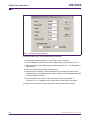
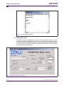
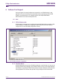
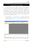
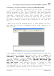
AN10404
Initialization code/hints for the LPC2000 family
Rev. 01 — 1 November 2005
Application note
Document information
Info
Content
Keywords
ARM assembly code, Initialization, Clock, Stack, power consumption
Abstract
Provides initialization steps, hints for reducing power consumption and
code examples that would get the LPC2000 device ready for the target
application
AN10404
Philips Semiconductors
Initialization code/hints for the LPC2000 family
Revision history
Rev
Date
Description
01
20051101
Initial version
Contact information
For additional information, please visit: http://www.semiconductors.philips.com
For sales office addresses, please send an email to: [email protected]
AN10404_1
Application note
© Koninklijke Philips Electronics N.V. 2005. All rights reserved.
Rev. 01 — 1 November 2005
2 of 15
AN10404
Philips Semiconductors
Initialization code/hints for the LPC2000 family
1. Introduction
This application note provides guidelines that have to be taken into consideration while
writing your software application for the LPC2000 family. Effort has been done to cover
most of the issues that could affect certain aspects of the end-application.
The application note has been divided into the following sections:
1. Initialization guidelines
2. Notes on the On-chip Bootloader
3. Reducing power consumption
4. Code examples
5. Software Tool Support
6. Additional Resources
2. Initialization guidelines
Most ARM applications begin by executing an assembly startup file. This file could be
linked to the bottom of the on-chip memory (Flash (0x0) or SRAM (0x400 0000)) or Bank
0 (for devices with an external memory interface) depending from where the application is
targeted to run. The following should be covered in this startup file:
1. Interrupt Vector table
2. Stack pointers
3. Branch to Main
After the above basic assembly initialization code is executed, a branch is done to C
main(). The following steps could be carried out in C code:
1. Enable the Memory Accelerator Module (MAM) if the application is run from on-chip
Flash. It provides accelerated execution at higher frequencies and also helps in
reducing power consumption. The MAM is only available in devices with on-chip
Flash.
2. Set the System clock and peripheral clock. The system clock can be boosted using
the PLL to 60 MHz or 75 MHz (for LPC2220) depending upon the input frequency.
The peripheral clock can be set using the VPB Divider register (VPBDIV at address
0xE01F C100). Please refer to Application note AN10331 to get detailed information
about the PLL.
3. Set the Memory Mapping Control register (MEMMAP at address 0xE01F C040)
accordingly. The MEMMAP register gives the application the flexibility of executing
interrupts from different memory regions. For instance, if MEMAP is set to 0x2, the
interrupt vectors would be mapped to 0x4000 0000 (bottom of on-chip SRAM).
4. Disable unused peripherals using the Power Control for Peripherals register (PCONP
at address 0xE01F C0C4).
5. Configure GPIO’s using the respective IODIR, IOSET and IOCLR registers. On the
LPC2000, there are certain pins that should not be held low on reset. For instance, by
driving P0.14 low on reset would make the on-chip bootloader to take control of the
part after reset (Please refer to the Flash Memory System and Programming Chapter
AN10404_1
Application note
© Koninklijke Philips Electronics N.V. 2005. All rights reserved.
Rev. 01 — 1 November 2005
3 of 15
AN10404
Philips Semiconductors
Initialization code/hints for the LPC2000 family
in the User Manual for detailed information). There could also be an additional pin in
certain devices which should not be held low on reset. If low on reset, then the device
behavior is not guaranteed. The following are the pins in various devices:
a. In LPC213x and LPC214x devices, P0.31 should not held low on reset
b. In LPC2114/2124/2212/2214/2119/2129/2194/2290/2292/2294/2210 and 2220
devices, P0.26 should not be held low on reset.
6. Depending upon the peripherals being used set the port functions accordingly using
the appropriate Pin Function Select register (PINSELx).
7. Initialize the peripherals which are still enabled in PCONP and enable interrupts for
them if needed.
8. Configure the Vectored Interrupt Controller (VIC) to handle the different interrupt
sources and classify them as IRQ and FIQ. It is recommended that only one interrupt
source should be classified as an FIQ. For more detailed information on Interrupt
handling please refer to Application notes AN10254 (Handling Interrupts using IRQ
and FIQ) and AN10381 (Nesting of interrupts in the LPC2000).
9. It is always safe to program the Default Vector Address Register (VICDefVectAddr at
address 0xFFFF F034) with a dummy ISR address wherein the VIC would be updated
(by performing a write operation on the VIC Vector Address register (VICVectAddr at
address 0xFFFF F030) to avoid any spurious interrupts.
3. Notes on the On-Chip Bootloader
3.1 Communicating with the Bootloader via Tera Term Pro/
HyperTerminal
Communicating with the bootloader (via the Serial port) is a fairly easy task and can be
done in multiple ways. Considering the evaluation board on which the LPC2000 device is
mounted has a RS-232 connector interfaced to UART0, a PC Terminal program (for
instance Tera Term Pro or Hyperterminal) can talk to the device by issuing various
In-System Programming (ISP) commands (as mentioned above, to enter this mode P0.14
would be held low on reset). More information on ISP can be found at the “Flash Memory
System and Programming Chapter” in the respective device User Manual. Please follow
the below steps to communicate with the LPC2000 on-chip bootloader through UART0
using Tera Term Pro.
Tera Term Pro settings would be as follows:
AN10404_1
Application note
© Koninklijke Philips Electronics N.V. 2005. All rights reserved.
Rev. 01 — 1 November 2005
4 of 15
AN10404
Philips Semiconductors
Initialization code/hints for the LPC2000 family
Fig 1. Tera Term serial port settings
Follow the below steps to communicate with the bootloader:
1. Send synchronization character “?” (0x3F) and wait for a response.
2. The LPC2000 device would return with the ASCII string “Synchronized<CR><LF>”.
3. Reply back with the same ASCII string “Synchronized<CR><LF>”. The bootloader is
case-sensitive.
4. The device would reply back with “OK<CR><LF>”.
5. Send the crystal frequency in KHz at which the part is running. For instance if the
crystal frequency is 12 MHz then send “12000”. The part is now initialized and the ISP
command handler is invoked.
6. The host machine can now issue ISP commands. An Unlock command “U
21130<CR><LF>” is needed to execute Flash Write, Erase and Go commands.
A snapshot from Tera Term Pro been interfaced to the LPC2148 is shown below:
AN10404_1
Application note
© Koninklijke Philips Electronics N.V. 2005. All rights reserved.
Rev. 01 — 1 November 2005
5 of 15
AN10404
Philips Semiconductors
Initialization code/hints for the LPC2000 family
Fig 2. Tera Term interface settings
3.2 Philips ISP utility
To avoid the trouble of interfacing the device each time using the above process, Philips
provides a Visual Basic Application which is free for download at the Philips website. For
more information on using this utility please refer to the application note AN10302 (Using
the Philips LPC2000 Flash Utility with the Keil MCB2100 and the IAR LPC210x kickstart
evaluation boards) available online.
Fig 3. LPC2000 Flash Utility screenshot
AN10404_1
Application note
© Koninklijke Philips Electronics N.V. 2005. All rights reserved.
Rev. 01 — 1 November 2005
6 of 15
AN10404
Philips Semiconductors
Initialization code/hints for the LPC2000 family
3.3 Bootloader version
Certain devices in the LPC2000 family need to have the latest bootloader versions.
LPC2114/2124/2212/2214/2119/2129/2194/2290/2292/2294 and 2210 need to have
bootloader version 1.63 or higher. LPC2104/5/6 needs to have version 1.52 or higher. A
field update package is available online at our website and it is named “LPC2000
Bootloader update via ISP”.
3.4 Code Read Protection (CRP)
CRP can be enabled by programming the flash address location 0x1FC with value
0x87654321 (2271560481 decimal). More details on CRP can be found in the “Flash
Memory System and Programming” Chapter in the respective User Manual. CRP is not
available with the LPC2104/5/6.
4. Reducing power consumption
Below are some hints which will reduce power consumption.
1. All the LPC2000 devices have two power saving modes: Idle and Power down.
Please refer to the Power Control section in the System Control Block chapter in the
User Manual.
2. Enable the MAM if the application is run from the on-chip Flash. Enabling the MAM
will enable various buffers and reduces the number of Flash fetches thereby reducing
power consumption.
3. Disable unused peripherals using the PCONP register.
4. The peripherals can run at a lower speed as compared to the ARM7 core frequency.
Using the VPBDIV register, the peripherals can run at either half or one-fourth of the
system frequency.
5. Most embedded applications, terminate with a while(1) loop and they service
interrupts whenever needed. In this case, code is still constantly fetched from the
on-chip Flash and executed which adds to the power consumption. A better solution
would be to switch to the Idle power saving mode and then wait for interrupts. An
interrupt from a peripheral would then wake the device from Idle mode. Considerable
power savings can be achieved by keeping the ARM7 core in Idle mode while it is
waiting for interrupts.
6. As mentioned above, Flash fetches adds to power consumption. If the program is
encoded using the Thumb instruction set then with each Flash fetch eight instructions
are fetched instead of four (as compared to ARM). Thus, the number of Flash fetches
could be reduced by using Thumb code.
7. To reduce current consumption on the 3.3 V rail in power-down mode (let’s consider
the 144-pin devices):
a. There are 80 pins with internal pull-ups on Ports 1, 2 and 3. These pull-ups are
always active.
b. Set those pins high or keep them floating before entering power down mode. If set
low, they will consume around 50 µA (typical) on each pin.
c. Port 0 does not have any internal pull-ups. These pins can be set low.
AN10404_1
Application note
© Koninklijke Philips Electronics N.V. 2005. All rights reserved.
Rev. 01 — 1 November 2005
7 of 15
AN10404
Philips Semiconductors
Initialization code/hints for the LPC2000 family
d. In LPC2114/2124/2212/2214/2119/2129/2194/2290/2292/2294 and 2210, there is
leakage current (around 200 µA) on External Interrupt/ADC pins if these pins are
pulled higher than 1.8 V. External Interrupt pins will contribute to the leakage
irrespective of the pin configuration. ADC pins will contribute to the leakage only if
they are configured as analog inputs.
8. On a side note, since the on-chip SRAM controller incorporates a write-back buffer
which holds the last data sent by software to the SRAM, a dummy write needs to be
done before entering idle or power down mode to avoid losing the data after a
subsequent reset. Hence, it is a good practice to write to a variable twice before
entering either power saving mode. Please refer to section On-Chip Static RAM
(SRAM) in Chapter 1 of the respective User Manual for more detailed information.
5. Code example
5.1 Startup assembly code
5.1.1 Interrupt vector table
In this code section, the interrupt vectors are set up for the ARM7 core. It would be linked
to the bottom of the memory (If running from external memory this code will be run from
Bank0). Comments in the code below are preceded by “;”. This might vary depending
upon the Assembler being used.
LDR
LDR
LDR
LDR
LDR
PC,
PC,
PC,
PC,
PC,
=Reset_Addr
Undefined_Addr
SWI_Addr
Prefetch_Addr
Abort_Addr
; At 0x14 the user should insert a signature (checksum).
; This signature enables the bootloader to determine if
; there is valid user code in the Flash. Currently most of
; the Flash programming tools (even the Philips ISP utility
; have this feature built–in so the end user need not worry
; about it. If the tool does not provide this feature then
; the value has to be computed manually and has to be
; inserted at 0x14. Details on computation of checksum
; could be found in the Flash programming chapter in the
; device User Manual.
DCD … .
; The below instruction is the IRQ vector and it will load the
; PC with the ISR of the highest priorty interrupt from the
; VIC Vector Address Register (VICVectAddr at address 0xFFFFF030).
LDR PC, [PC, #–0xFF0]
; The ISR for FIQ can start from the below address itself.
LDR PC, FIQ_Addr
Undefined_Addr
SWI_Addr
DCD
DCD
Undefined_Handler
SWI_Handler
AN10404_1
Application note
© Koninklijke Philips Electronics N.V. 2005. All rights reserved.
Rev. 01 — 1 November 2005
8 of 15
AN10404
Philips Semiconductors
Initialization code/hints for the LPC2000 family
Prefetch_Addr
Abort_Addr
FIQ_Addr
;
;
;
;
;
DCD
DCD
DCD
Prefetch_Handler
Abort_Handler
FIQ_Handler
–––––––––––––––––––––––––––––––––––––––––––––––––––––––––
Exception Handlers
–––––––––––––––––––––––––––––––––––––––––––––––––––––––––
The following dummy handlers do not do anything useful in
this example. They are set up here for completeness.
Undefined_Handler
SWI_Handler
Prefetch_Handler
Abort_Handler
FIQ_Handler
END
B
B
B
B
B
Undefined_Handler
SWI_Handler
Prefetch_Handler
Abort_Handler
FIQ_Handler
On reset, the first instruction to be executed would be
LDR PC, =Reset_Addr
Once this instruction is executed, a jump is done to “Reset_Addr”. From here, the
interrupts need to be enabled and the stack pointers for the various modes need to be set
before jumping to C main().
5.1.2 Setting up Stack Pointers and Enabling Interrupts
While setting the stack pointer please note that the Flash programming routines use a
section of the on-chip SRAM. In-System Programming (ISP) uses the top 256 bytes and
In-Application Programming (IAP) uses the top 128 bytes of the on-chip SRAM. The
application stack should not overlap this area.
; Enabling interrupts in the CPSR and keeping the part
; in Supervisor mode after ARM7 core reset
MSR cpsr_c,#0x13
; Setting up SP for Supervisor Mode
LDR SP,0x4...
; Setting up the SP for various modes can be done in
; several ways. Below is the sample code for setting the
; SP for IRQ mode (SP_irq). After setting the SP_irq, the mode is
; switched back to Supervisor Mode.
MRS R0, CPSR
BIC R1, R0,#0x1F
ORR R1, R1,#0x12
MSR cpsr_c, R1
LDR SP, =0x4…..
MSR cpsr_c, R0
AN10404_1
Application note
© Koninklijke Philips Electronics N.V. 2005. All rights reserved.
Rev. 01 — 1 November 2005
9 of 15
AN10404
Philips Semiconductors
Initialization code/hints for the LPC2000 family
Please note that incorrect setting of the SP can cause the ARM7 core to cause a Data
Abort. After setting the stack pointers, the program counter would be ready to be linked to
C main().
5.2 C code
int main()
{
// The MAMTIM value would depend upon the system clock desired
// MAM is fully enabled below
MAMTIM=0x...;
MAMCR=0x2;
// Setup the system clock to the desired clock frequency
// The PLLCFG value is provided for input frequency of 12 MHz
// and the desired system frequency is 60 MHz
PLLCFG=0x24;
feed();
// Enabling the PLL
PLLCON=0x1;
feed();
// Wait for the PLL to lock to set frequency
while(!(PLLSTAT & PLOCK)){}
// Connect the PLL as the clock source
PLLCON=0x3;
feed();
// Set the peripheral clock. Here we set it to 60 MHz
VPBDIV=0x1;
// This would now be followed by the user code depending upon
// the application and guidelines mentioned above
While(1)
{}
}
// Feed sequence for the PLL
void feed()
{
PLLFEED=0xAA;
PLLFEED=0x55;
}
AN10404_1
Application note
© Koninklijke Philips Electronics N.V. 2005. All rights reserved.
Rev. 01 — 1 November 2005
10 of 15
AN10404
Philips Semiconductors
Initialization code/hints for the LPC2000 family
6. Software Tool Support
We have support from several software tool vendors for our LPC2000 family. In this
application note, we have taken some key features that are provided by Keil and IAR
Systems. Also listed below is “The Insiders guide to the Philips ARM7-Based
Microcontrollers” from Hitex Development tools.
6.1 Keil
6.1.1 GUI for Startup code
Keil has made it extremely easy to configure the Assembly Startup file by providing a GUI.
In this startup file, in addition to configuring the stack, they also provide the ability to
configure the PLL and the MAM (configuration window).
Fig 4. Keil assembly startup file configuration
6.1.2 Simulator Mode
Keil has implemented most of the LPC2000 peripherals in their Simulator. It’s easy to use
and also provides easy debugging of the software before running on the target hardware
itself. Below is a screenshot of their GPIO simulation. Similar simulations can be found for
other peripherals.The simulator also provides a Logic Analyzer and a serial window.
AN10404_1
Application note
© Koninklijke Philips Electronics N.V. 2005. All rights reserved.
Rev. 01 — 1 November 2005
11 of 15
AN10404
Philips Semiconductors
Initialization code/hints for the LPC2000 family
Fig 5. GPIO simulation screenshot
6.2 IAR Systems
IAR provides their startup code so that the end-user gets a jump-start into their application
by starting to code to C itself. The startup code usually named as “lpc2xxx_cstartup.s79”
can be found with the example projects that accompany the software.
6.2.1 IAR MakeApp
IAR MakeApp provides a highly visual workspace for the configuration for certain
LPC2000 devices in 48, 64 and 144-pin packages. Device-driver code is created
automatically and the application software gets instant access to the peripherals of the
microcontroller. This tool is available for free download at the MakeApp website.
6.2.2 IAR visualSTATE
visualSTATE is a suite of graphical design automation tools for embedded systems. An
embedded system can be designed using a flowchart model. Extensive testing can be
performed which includes validation of the application behavior, regression testing and
simulation on-chip. Finally, it can create micro-tight C/C++ code which is consistent with
the design specifications coupled with a complete design documentation.
6.3 Hitex Development Tools
Hitex Development Tools support the LPC2000 family with their toolchain. In addition to
this support they have also prepared a very resourceful book called “The Insiders guide to
the Philips ARM7-Based Microcontrollers”. This book is free for download at both the
Philips and Hitex websites and provides useful information regarding our devices.
The Insider's Guide can be used as the basis of a self-teaching course when used with
the Keil µVISION3 compiler IDE. All the examples included with the Guide can be built for
either the simulator or the MCB2100 evaluation board. For more information please visit
the Hitex Development Tools website.
AN10404_1
Application note
© Koninklijke Philips Electronics N.V. 2005. All rights reserved.
Rev. 01 — 1 November 2005
12 of 15
AN10404
Philips Semiconductors
Initialization code/hints for the LPC2000 family
Fig 6. Covershot of hitex programmer’s guide
7. Additional Resources
1. Philips Semiconductors website, which allows access to Philips support.
2. LPC2000 Yahoo forum. Founded on November 17th 2003, this Yahoo forum is
dedicated to the LPC2000 Family. It has over 2000 members and provides the best
online support. Be sure to refer to the Files section of this group for sample board
schematics, software etc.
3. ARMTDMI-S Technical Reference Manual. The LPC2000 family is based on the
ARM7TDMI-S core. The technical reference manual is free for download on the ARM
website.
AN10404_1
Application note
© Koninklijke Philips Electronics N.V. 2005. All rights reserved.
Rev. 01 — 1 November 2005
13 of 15
AN10404
Philips Semiconductors
Initialization code/hints for the LPC2000 family
8. Disclaimers
products, and makes no representations or warranties that these products are
free from patent, copyright, or mask work right infringement, unless otherwise
specified.
Life support — These products are not designed for use in life support
appliances, devices, or systems where malfunction of these products can
reasonably be expected to result in personal injury. Philips Semiconductors
customers using or selling these products for use in such applications do so
at their own risk and agree to fully indemnify Philips Semiconductors for any
damages resulting from such application.
Application information — Applications that are described herein for any
of these products are for illustrative purposes only. Philips Semiconductors
make no representation or warranty that such applications will be suitable for
the specified use without further testing or modification.
Right to make changes — Philips Semiconductors reserves the right to
make changes in the products - including circuits, standard cells, and/or
software - described or contained herein in order to improve design and/or
performance. When the product is in full production (status ‘Production’),
relevant changes will be communicated via a Customer Product/Process
Change Notification (CPCN). Philips Semiconductors assumes no
responsibility or liability for the use of any of these products, conveys no
licence or title under any patent, copyright, or mask work right to these
9. Trademarks
Notice — All referenced brands, product names, service names and
trademarks are the property of their respective owners.
AN10404_1
Application note
© Koninklijke Philips Electronics N.V. 2005. All rights reserved.
Rev. 01 — 1 November 2005
14 of 15
AN10404
Philips Semiconductors
Initialization code/hints for the LPC2000 family
10. Contents
1
2
3
3.1
3.2
3.3
3.4
4
5
5.1
5.1.1
5.1.2
5.2
6
6.1
6.1.1
6.1.2
6.2
6.2.1
6.2.2
6.3
7
8
9
Introduction . . . . . . . . . . . . . . . . . . . . . . . . . . . . 3
Initialization guidelines . . . . . . . . . . . . . . . . . . . 3
Notes on the On-Chip Bootloader . . . . . . . . . . 4
Communicating with the Bootloader via Tera Term
Pro/ HyperTerminal . . . . . . . . . . . . . . . . . . . . . . 4
Philips ISP utility . . . . . . . . . . . . . . . . . . . . . . . . 6
Bootloader version . . . . . . . . . . . . . . . . . . . . . . 7
Code Read Protection (CRP) . . . . . . . . . . . . . . 7
Reducing power consumption . . . . . . . . . . . . . 7
Code example . . . . . . . . . . . . . . . . . . . . . . . . . . 8
Startup assembly code . . . . . . . . . . . . . . . . . . . 8
Interrupt vector table. . . . . . . . . . . . . . . . . . . . . 8
Setting up Stack Pointers and Enabling
Interrupts. . . . . . . . . . . . . . . . . . . . . . . . . . . . . . 9
C code . . . . . . . . . . . . . . . . . . . . . . . . . . . . . . 10
Software Tool Support . . . . . . . . . . . . . . . . . . 11
Keil . . . . . . . . . . . . . . . . . . . . . . . . . . . . . . . . . 11
GUI for Startup code . . . . . . . . . . . . . . . . . . . . 11
Simulator Mode . . . . . . . . . . . . . . . . . . . . . . . 11
IAR Systems . . . . . . . . . . . . . . . . . . . . . . . . . . 12
IAR MakeApp . . . . . . . . . . . . . . . . . . . . . . . . . 12
IAR visualSTATE . . . . . . . . . . . . . . . . . . . . . . 13
Hitex Development Tools . . . . . . . . . . . . . . . . 14
Additional Resources . . . . . . . . . . . . . . . . . . . 15
Disclaimers. . . . . . . . . . . . . . . . . . . . . . . . . . . . 17
Trademarks. . . . . . . . . . . . . . . . . . . . . . . . . . . . 17
© Koninklijke Philips Electronics N.V. 2005
All rights are reserved. Reproduction in whole or in part is prohibited without the prior
written consent of the copyright owner. The information presented in this document does
not form part of any quotation or contract, is believed to be accurate and reliable and may
be changed without notice. No liability will be accepted by the publisher for any
consequence of its use. Publication thereof does not convey nor imply any license under
patent- or other industrial or intellectual property rights.
Date of release: 1 November 2005
Document number: AN10404_1
Published in The Netherlands