1
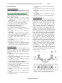
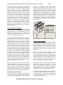
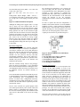
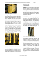
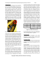
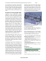
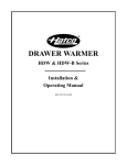
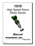
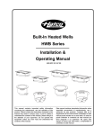
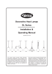
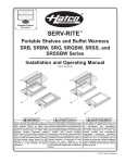
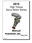
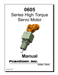
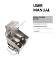
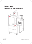
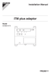
Multi-Disciplinary Engineering Design Conference Kate Gleason College of Engineering Rochester Institute of Technology Rochester, New York 14623 Project Number: 8351 DESIGN AND DEVELOPMENT OF AN AUTOMATED OILING SYSTEM Matt Zapotoski Project Leader Industrial Engineering Bob Shackelford Lead Engineer Mechanical Engineering Joe Jennings Design and material lead Mechanical Engineering ABSTRACT This paper describes the design of an oiling machine for Parlec, a local company whose most profitable product line is tool holders. The bottleneck in the process currently exists at the oiling operation. The existing process is as follows: tool holders are manually dipped in oil bins, shaken, and dried on paper towels. Since this task is operator driven, chances for error and inconsistency exist. In a market in which there is growing emphasis on aesthetics, such an operation is non value added. In response, Parlec has requested a machine that will greatly improve the oiling process, and ultimately eliminate any inconsistency while increasing the output quality. Over 22 weeks, a fully functional test prototype was designed, fabricated, and tested. PROJECT BACKGROUND The tool holders from Parlec are manufactured to maintain precision, functionality, and durability. Trying to increase productivity by 30%, they are shifting processes throughout the facility. The operation focused on for this project is the oiling of the parts currently manufactured. Once the parts are manufactured, the company name is applied via laser and loaded onto racks. Theses parts are then taken and individually oiled, dried, and packed into boxes. The oiling is done to avoid any oxidation or rusting of the products. The current bottleneck in this assembly process exists in the operations following the laser stage. Aside from hindering the throughput, the current operation is inconsistent, and has lead to quality problems. Sharif Hdairis Electrical components lead Computer/Electrical Engineering The machine incorporated the following subsystems: loading, cleaning, oil application, removal of excess oil, and unloading. Everything was planned to be automated except for the loading and unloading of the tool holders. The main goal and motivation of this project was to build a machine that removes the human portion out of the oiling process, thus eliminating the inconsistencies associated with the output of low quality parts. This machine will also allow for continuous flow, helping to reduce bottlenecking and stoppages in the line. In the first ten weeks, a highly detailed machine was designed, that met all of the customer’s specifications. The anticipated cost did not exceed the $20,000 budget. However, due to unforeseen complications and a smaller budget than anticipated, a prototype containing the uncertainties of the project was designed. Over the next ten weeks, the two primary uncertainties associated with the design: the overall versatility of the pin on which the parts are mounted on and the transport mechanism, along with the removal of excess oil with air were tested with a redesigned test prototype that was approximately $700 to build. This contributed heavily to the justification and validation of the fully designed machine. The project team, comprised of an Industrial Engineer, two Mechanical Engineers and an Electrical/Computer Engineer, was organized to achieve this. © 2008 Rochester Institute of Technology Proceedings of the KGCOE Multi-Disciplinary Engineering Design Conference DESIGN PROCESS Customer Requirements In the first phase of the design process, a list of customer requirements was provided by Parlec. This list can be found on the team webpage https://edge.rit.edu/content/P08351/public/Home. This list was revised during meetings with the primary customer contact, Patrick Torres, to include the following requirements: The machine will take the human element completely out of the operation (minus loading and unloading) The product will help promote continuous flow, hence decrease the amount of bottlenecking The machine meets all relative OSHA standards The product fits within the floor layout The machine has variable speeds The product will require minimal changeovers The oiling process will consistently oil all of the parts. The product must be safe for workers and bystanders. A user manual is provided so that Parlec employees can easily access information regarding the use of the product and preventative maintenance. The area in which oiling occurs will be fully enclosed. The machine will be user friendly: easy to start, run, and stop. The machine will minimize oil waste. The machine will have a simplified procedure regarding the removal or replacement of any filters, hooks, or other exchangeable component. Design Specifications In the second phase of the design process, the customer requirements were translated into engineering metrics using the Quality Function Deployment method. The design specifications are listed below: The machine can support toolholders with weights up to 40 lbs. The machine can handle toolholders with lengths ranging from 3 to 18 inches. The machine can hold toolholders with inner diameters up to 7 inches. The oiling process will oil the complete exterior of the part (interior throughhole negligible). The tool holders 60 millionths of 1 inch part tolerances will be maintained. The machine must meet the throughput of 1400 pieces /shift (200 per hour). The machine will be no larger than 15 ft long and 8 ft wide. The machine has at least two emergency stop buttons. The product will have an oil pan implemented to retain any excess oil. Page 2 The oil tank will have a means of accessibility such as a door. The product has proper protective guards where necessary. The device can function for one full shift (7-8 hours per day). The machine will be transportable (will have forklift slots). The total cost of the device will be under $20,000. Concept Development By creating a flow chart, all the customer needs were divided into the five subsystems: loading/unloading, cleaning/removal of excess oil, application of oil, part holding type, and the variable speed drive. Each subsystem was broken down further in which possible solutions that could be implemented to create a successful solution were developed. Once complete, the positives and negatives about each possibility were generated. This enabled for several concepts to be generated on how each substation will achieve its function. Next, concepts were developed for the entire system. This was done by using Pugh’s matrices for each of the sub functions, thus allowing the team to identify the top two or three alternatives for each subsystem. Once complete, the alternatives were randomly combined resulting in the development of a total of seven concepts for the system. Concepts for the system were then numbered and put into a matrix. Pugh’s Method was again used to help assist in screening the concepts. The end result was a visual of how each system scored when compared to the others. Also, it showed the strengths and weaknesses of each design, which led to combining the best concepts of the substations into one concept for the whole system that would out score any of our original concepts. The final concept is shown in Figure 1 seen below Figure 1: Final concept individual subsystems Paper Number 08351 Proceedings of the KGCOE Multi-Disciplinary Engineering Design Conference In the final concept design process, many different design solutions were suggested. The final concept shown in Figure 1 uses a pin to transport the part through the system. The part is loaded manually, blown off with air, dipped into an oil tank, blown off with air again, and then unloaded. The only missing element in the concept design is an oil pan that retains excess oil once parts are blown off following the oiling process. The method of powering the machine was pretty limited, with electricity being the evident solution due to cost and compatibility. In regards to the signals of the machine, controls (sensors) were put in place to allow the machine to know when to discharge compressed air. A variable speed drive was also assumed, as it will control the tempo of the system, and allow the user to change the speed as necessary. Page 3 quarter. It is essentially a stand alone manual machine that incorporates the same concepts of the proposed machine designed in Senior Design 1. This first phase allowed the team to clear up the doubts associated with the full design. From a real-world standpoint, this is more than appropriate, as investing $700 and ensuring it works before investing 20 plus thousand dollars is the logical and evident thing to do. This manual station however, is still much more efficient than the current process, and is expected to be incorporated in everyday operations at Parlec for the near future. Risk Assessment and Mitigation In order to determine the subsystems that would drive the final design, a risk assessment was performed and mitigating solutions were determined. The critical subsystems determined were: the versatility and durability of the pin concept and the efficiency of the air knives at fully blowing off the part. The risk that exists with choosing the pin is its ability to successfully handle the wide array of tool holders, ranging from Cat 30’s to Cat 50’s, all having different lengths (3 inches to 18 inches). If for some reason, the fabricated pin does not work as efficiently as planned during the testing stage, the design of the pin allows for it to be altered as necessary. The fact that the standard pin is manufactured at Parlec provides the team with the quickest and cheapest way to fabricate the part, as well as the ability to modify as necessary. The other risk associated with these pins is that they are currently used to solely hold the tool holders on racks, and transport them throughout the facility. Using the pin to transport the parts through the oiling machine will apply more stress, but the trolley is designed so the part will always remain perpendicular to the floor, lowering the amount of stress on the pin. If a pin breaks, it can be replaced by simply unscrewing the part from the support and replacing it with a new one. Due to uncertainty of how the air could be used, different configurations at which the air knife is positioned will have to be developed and tested. The primary objective is to completely blow of a part with a length less than or equal to 18 inches. The angle and orientation at which the air knives are positioned will be pivotal in successfully meeting this objective. DESIGN IMPLEMENTATION As previously stated, a scaled down test prototype was designed to test and validate critical components of the full design and then fabricated over the spring Figure 2: Side views of final test station design Ergonomic Implementation A top priority in designing this machine is meeting OSHA compliance, as well as sustaining the safety of the workers and any bystanders. Since oil is involved within the operation, it is necessary for the oiling operation and removal stage to be enclosed. This will prevent any oil/fumes from ever coming in contact with the user. The use of compressed air was deemed the most efficient way to clean off the parts. However, air can be loud, especially with blow off procedures. To prevent any damage to the operator’s ears, the OSHA requirements were referenced. The standard for every 8 hours of exposure is a decibel value of no more than 90. Once the test station is assembled, the decibel value will be measured and recorded. The height at which the tool holders will be loaded onto the pin will be no more than 2 ½ feet (30 inches). The NIOSH lifting equation was used with the heaviest part (40 lbs), to ensure that the operator will not be under any risk of injury. The calculations pertaining to this can be seen below in Figure 3. The machine features individual hooks that hold the tool holders. Since these hooks are slightly heavy, and would be tiring to transport from the loading side to the unloading side, a return rail was installed next to (parallel) the oiling process. Copyright © 2008 by Rochester Institute of Technology Proceedings of the KGCOE Multi-Disciplinary Engineering Design Conference Recommended Weight Limit (RWL) = LC x HM x VM x DM x AM x FM x CM RWL=51 x .286 x .865 x .925 x .312 x .35 x 1 = 1.27 lbs Lifting Index= Object Weight / RWL = 40/1.27 = 31.38 which is greater than 3, therefore most workers are at high risk of developing low-back pain and injury. Figure 3: NIOSH calculations/descriptions Although the lifting index suggests there is a high risk of injury, the most frequent parts that are manufactured are the CAT 30’s and CAT 40’s, which weigh significantly less. That being said, the NIOSH lifting equation was used for the maximum weight possible, but since the workers will not be lifting this weight for seven hours every day, there is far less risk than what the data above suggests. A more common part, such as the Cat 40 has an average weight between 2 and 3 lbs. After the weights were applied to the equation both produced a result less than 3, indicating that the lifting task does not pose high risk to the worker Electrical Components Selecting components for the electrical subsystem went under a couple of revisions to incorporate a cost-effective solution. One of the main differences between the prototype and projected design is that the majority of the components in the full-scaled machine were DC powered, and they had little programming capabilities. This in turn called for a central controller to synchronize the operation of the machine and provide input to the machine and feedback to the operator. With the essential concept tested in the prototype being the blow-off mechanism, it was determined that a semi-automated method for running the blowoff compartment will be necessary to prove that it can be automated, and the oil removal efficiency is adequate. The semi-automated operation means that the process is started manually by activating a pushbutton, and it stops automatically after a programmable time interval. To achieve this, a Magnecraft timer/relay combination was used which can handle up to 12A @ 120VAC (far more than what is required to power the connected air valves). The air valves selected were general purpose fluid valves that operate directly off a 120VAC outlet and handle 150psi at a throughput high enough to have the air-knives function properly (the minimum CFM value will be determined at the end of the testing phase). Page 4 By converting the components to AC powered, the need for a high power DC inverter was eliminated, saving approximately $225. Although the relay in the prototype is more expensive, it contained the programmable delay option which would have been offloaded to the microcontroller in the full-scaled system; the decision to use the time/relay combination saved time, reduced cost, and simplified the design. In order to operate this blow-off compartment, a standard 1-hole 22mm enclosure was used (NEMA-4 standard) to house a single mushroom pushbutton. When pressed, it starts the timer, and the valves are opened, allowing air to flow through the knives and remove the oil as the parts glide by on the tracks. A quick pin-out reference is provided in Figure 4 Figure 4: Pin-out of SRXP-series Timer/Relays Pin connections. 2, 10: relay/timer power source (120VAC) 1, 11: load power source (120VAC) 3, 9: load pins (air valves) 5, 6: control switch (pushbutton) 4, 7, 8: floating (No connections) Products and Materials The machine is made up of several components; this includes off the shelf products, as well as raw materials. The following parts were purchased off the shelf and required no alterations: the plastic tote used as the oil bath, the workbench supplied by Parlec that serves as the overall base for the machine, plastic wheel conveyors (supplied by the department of Industrial and Systems Engineering) that enable the movement of the parts in a conveyor-like fashion, air fittings for the air blow off mechanism, and a weld curtain to isolate the oil removal stage. Furthermore, hardware was required to combine the parts of the subsystem, leading to the purchase of bolts and nuts. Aside from the off the shelf products listed above, the prototype was built from scratch. This created a necessity for the fabrication of custom parts. In light of this, raw materials were essential in achieving this. Steel was relied on heavily, as the sheet pan was created from a sheet of steel that was bought and cut Paper Number 08351 Proceedings of the KGCOE Multi-Disciplinary Engineering Design Conference Page 5 to 24” by 28”. Three inches at the two sides were bent at 90 degree angles, resulting in a final oil pan 18” wide by 28” in length. It was creased in the middle to channel the oi, allowing it to flow in one remote stream. Low carbon steel was utilized to create the hook mechanism that holds the parts, as well as curtain mounts. This bar steel, originally six feet long, was put into a vice and bent at a 90 degree angle at one end (the bottom), and bent twice at 90 degree angles to form the top of the hook. Additionally, the overall supports and mounts for the system were comprised of numerous different sizes of angle iron. Six 40” lengths were cut and used as the uprights, four 25.5” lengths were used as the air knife supports, two 19 3/4” served as supports for the oil pan, and twelve 4 5/8” pieces served as the braces supporting the hooks. Some of the angling iron was cut at 45 degree angles, and used to construct the frame. This included four 26” lengths and four 34” lengths for the top and bottom. ABS plastic was purchased in a 12” sheet and cut into twelve 1” lengths. These were used as gliders for the movement of the steel transport arms (two for every support arm). The air knife was custom fabricated using square steel tubing 1” by 1” that was cut in two lengths at 24”. The tubes where then drilled and tapped for 1/8” air nozzles on one side of the tube at ten spots 2” apart starting at 3/4” from one end. The ends of the tubes were then capped off and welded with one end tapped out for a 3/8” air fitting attachment. Figure 5: side view of transport arm The angling iron components were drilled/bolted and welded together for ease of prototype manufacture. Welding was also chosen to prevent the assembly from coming apart as well as the possibility of the steel frame deforming over time. The frame is rectangular in shape (26” x 34”) with several pieces of different sizes arranged both horizontally and vertically. The pieces of angling iron all arranged at the top of the frame serve the purpose of aligning and securing the pieces of wheel conveyor, as they were bolted together. This process can be seen in Figure 6. Numerous holes were drilled into the frame, allowing for versatility of the exact height at which the parts will sit in the system, as well as toggling with different incline angles to control the movement of the arms. The oil pan was placed on the two 19 ¾” pieces of angle iron (front and back supports), and was then bolted to the frame at the sides. Assembly A number of machining techniques were used in the manufacture of the interfacing components. All pieces were created using a programmable three axis milling machining along with a programmable lathe. The oil pan was installed in the machine at a 13 degree angle facing downwards towards the front of the machine. This was implemented to encourage the flow of excess oil back into the original oil bin. The transport arm was created combining two 1” pieces of the ABS plastic parallel on each side of the low carbon steel. Two 4 5/8” pieces of the angling iron were then fastened perpendicularly to the ABS and steel; four holes were drilled (8 total) in each piece of angling iron: two securing the iron to the ABS plastic, and two securing the iron to the steel arm. The result was the transport arm. This finished assembly can be seen in Figure 5. Figure 6: top view of the frame/conveyor assy. The weld curtain was cut into seven pieces: one large piece that covered the top and sides (76” x 26”), as well as four other pieces (10” x 23”), two at each of the load and unload segments of the machine. The final two pieces were cut into 20” x 8” sheets with 5” openings in the middle to accommodate the conveyor. This design can be seen in Figure 7. Copyright © 2008 by Rochester Institute of Technology Proceedings of the KGCOE Multi-Disciplinary Engineering Design Conference Page 6 Mechanical Testing Figure 7: diagonal view of oil curtain The original design for the air knife was a 44 inch piece of square steel tubing with a 90 degree bend at one end four inches long. The design featured holes drilled and tapped, enabling the air nozzles to be inserted. The nozzles were going to be every other inch. However, when fabricating this part, the 90 degree bend was not made (if determined to be needed it will be attached and welded). The nozzles were inserted every two inches (with every other inch still a possibility). This was done to see if: airflow would be adequate throughout, as well as preventing unnecessary fabrication. In order to mount the air knives, they were welded to 1/2” x 1/8” flat bar was cut into 10” sections. This assembly was then mounted to support arms- angle iron (6”) with 7 holes drilled in them for adjustability attached to the frame with 5/16” bolts. The great feature of this setup is that the alignment of the air knife can be adjusted both vertically and horizontally. This concept and the final positioning of the air knives is depicted in Figure 8. Air Knife The other initial test that was conducted was hooking the air knife up to the valve and the air source. Doing this before attaching the air knives to the machine served very beneficial as it turned out (after all proper connecting parts were purchased) the valves the team initially purchased were constricting the air flow greatly. So the team decided to purchase two more of the original valves, sending two to each air knife. This allowed for twice the amount of air, making up for the air flow constriction. Functionality Test As the device was assembled and put together, parts were tested for verification purposes. Once the frame and conveyor were combined, the arms were run down the tracks simultaneously. The arms moved as planned, but for some reason would “jump” when reaching the end of the track. This was due to the overhanging part of the arm colliding with the connectors at the end (which added thickness to the conveyor, hence decreasing the distance between the two rails). This was rectified by grinding each side of the overhang. The specific area in which this customization was done can be seen in Figure 9. Figure 9: guide that required grinding One concern was a versatile pin design that could accommodate the majority of the product line. The delrin pin was mounted on the above arm, and its versatility was proven in successfully transporting CAT 30s, CAT 40s, and CAT 50s through the system. Figure 8: air knives installed into machine DESIGN VALIDATION: TESTING AND RESULTS Once the implementation was complete, it was necessary to test the device to make sure that it met all the agreed-upon customer requirements. Tests are outlined below including some of the calculations included in them. The system instilled to capture oil served its purpose in not only preventing any oil from escaping, but retaining it as well. The only issue with the weld curtain was the flaps at the front and end of the machine staying open due to the blowing of the air. Negligible amounts (mist) of oil escaped, but in order to maintain cleanliness of the machine and safety for the user, no discharge is obviously preferred. The oil tray worked as expected in channeling the blown off oil back towards the front of the machine into a single flow. Paper Number 08351 Proceedings of the KGCOE Multi-Disciplinary Engineering Design Conference Oil Removal Test The big part of the test prototype was proving that the air blow off mechanism adequately removed 90% of the oil on the part. In other words, the majority of the oil on the exterior is removed. (The oil inside the interior of the part is expected to remain, but should not be a sufficient amount to matter). In order to do successfully achieve this, the air knife was first positioned at different rotational positions of 90, 60, 45, and 30 degrees. The team also wanted to mount the units at different angles (0, 15, 25 degrees), but due to their length only 0 or 15 degrees was allowed as the conveyor system interfered with the upper part of the air knife when moving it in diagonally. This complication can be seen in Figure 10. The other factor that was taken into account was the overall distance from the nozzles to the pin. The initial thought with this test was the closer the better, but it was tested for verification purposes. Page 7 previously. In regards to the oil collection on the flat surfaces above the tapers, the air knives were pitched downwards towards the part at angles of 15 degrees. This solved the problem immediately as the air blowing downward onto the part from both sides either pushed it off the side or further down the part. As previously stated, the overhanging conveyor allowed us to angle the air knives at 15 degrees. In order to implement this, the air knives had to be moved horizontally away from the parts passing through. Initially, the horizontal distance from the pin to the corresponding nozzle to the outer most edge of the passing part (CAT 40) was between 1 and 2 inches. When the angling of the air knives was adjusted, the distance increased to 4 inches. The machine functioned wonderfully and accomplished the needs specified by the customer. Two CAT 40s were manually run through the machine with the timer for the air set at an interval of ten seconds. The PSI of the air used was 80, meaning the full potential 120 PSI existing at Parlec was not tested. The results of the five test trials can be seen in Figure 11 below. part saturated with oil 1058.950 g 1058.975 g 1059.875 g 1058.325 g 1058.575 g part after blowoff process Difference 1052.425 g 6.525 g 1052.60 g 6.375 g 1054.25 g 2.625 g 1053.85 g 4.475 g 1054.30 g 4.275 g AVG 4.855 g * un-oiled part weighs an average of 1051 g Figure 11: results of oil removal test Figure 10: conveyor deterring movement of knife The first test involved toggling the rotational position at which the air knives faced the part perpendicularly. In testing the four different angles, the conclusion drawn was that the lower the angle, the better overall coverage of the part. When both air knives were rotated 30 degrees, a significant lesser amount of oil remained on the part when compared to the air knives rotated at 90 degrees. To test all possibilities, one air knife remained at 30 degrees, while the other was rotated to 45, 60, and 90. This did work much better than having both at the higher orientations (60 and 90), but did not replicate the performance of having the two units facing the oncoming tool holder at 30 degree angles. On a side note, positive that oil is collecting where we predicted, dripping onto the pan and flowing back into the bin An observation made when watching the tool holders run through the air, was that the oil was pooling in two specific areas. Those being the base of the plastic hook holding the part, as well as the flat surface above the taper on the part. The pooling at the pin was rectified by milling a slit down one side of the pin. This allowed the oil to flow down from the part, preventing the excessive buildup that was occurring By saving 4.855 grams of oil per part, and producing 1400 tool holders per shift, the expected savings of oil per day is approximately 1.98 gallons. Electrical Testing All of the electrical components of the system functioned as the team intended. The start switch prompted the air blow off to initiate, while the timer controlled the specific time precisely. Ergonomic Testing The decibel level of the air knives was measured, and recorded to be 85dB. This makes the machine OSHA compliant, posing no threats to hearing loss over an 8 hour shift. CONCLUSIONS When looked at as a whole, the team agrees that the project is an overall success. The majority of key customer needs were met, and those that weren’t, could be met through the purchase of the automated machine. Although the range of abilities provided by the machine was not as broad as originally intended, it not only served as a prototype proving the validity of the proposed machine (The two major concepts of the project with the highest uncertainty, the pin/transport arm and the air knives were proved to Copyright © 2008 by Rochester Institute of Technology Proceedings of the KGCOE Multi-Disciplinary Engineering Design Conference be successful), but also provided a fully functional device that provides a much more efficient process than the one that currently exists at Parlec. A test plan was used to compare the design specifications with the project outputs. All of the design specifications were successfully achieved. Members of Parlec are satisfied with the design and functionality of the device. RECOMMENDATIONS FOR FUTURE WORK In terms of the existing prototype, specific modifications could be implemented to improve performance. In order to achieve the most favorable removal of oil, more nozzles could be inserted into the air knife, as they were initially spread out every two inches to ensure that adequate air flow could be achieved among the nozzles. Nozzles every inch would promote a larger range of coverage for each passing part. Another alteration that would optimize performance would be to cut 4” off the top of each air knife, and re-weld the closed end with the air fixture back on. This would enable the air knives to be positioned closer to the passing product. As mentioned earlier, the 1/8” air valves used (not designed for high air flow) constricted air flow, presenting the need to allocate two to each air knife. This in turn lead to excess hardware required for connecting them together, and to the whole system, in due course restricting air flow even further. Two possible solutions exist to promote the most efficient air flow: buying an actual air knife, which is expensive, but designed for similar applications, or implementing larger (3/8” or larger) valves that will facilitate the flow of air throughout the system. Other additions/changes that could be made to the machine include: additional slots milled into the delrin pin, enhancing the flow of oil from the part to the oil pan. Thicker material for the flaps on the entrance/exit would prevent them from blowing up, thus allowing oil particles to escape. If not, the current material could be anchored down to keep the enclosed area isolated. The ideal future project in mind is the fabrication of a semi-automated machine that incorporates the concepts proven by the test prototype discussed in this paper. The intent for this machine is to eliminate more of the human aspect of the operation, reducing it to loading and unloading. The plan for the machine involves the loading of tool holders onto the pin used in the machine, fastened to an arm suspended from an overhead chain conveyor. Each arm will be separated 18 inches from the other, moving at a set speed of approximately 5 feet per minute (the speed required to output 1400 units in a 7 hour shift. Once loaded, the part will be blown off with two air knives (one on each side), then down a decline (in the shape of a “U”) at a 45 degree angle. The part will be Page 8 submerged with oil, with the tank being designed to handle parts ranging from 2 to 18 inches in length. After leaving the oil tank the tool holders will be sprayed with air again, blowing off excess oil back into the tank. Following this, the part is ready to be unloaded, and can be done so for the next 18 feet before being run through the system again.A drawing of this proposal can be seen below in figure 12. Figure 12: proposed future machine ACKNOWLEDGEMENTS The team would like to thank Parlec, specifically Pat Torres the Nutticelli family for the funding and support that made this project possible. Sincere appreciation goes out to Dr. James Taylor and Prof. John Kaemmerlen for their constant guidance and support throughout the entire 22 weeks of the Multidisciplinary Senior Design program. - The staff of the Machine shop; especially Dave Hathaway, for allowing the team to use the facilities and willingly helping when able. - Mark Smith and Chris Fisher for allowing the use of the Senior Design lab every Friday. - Anthony Barco and Rocon Manufacturing for supporting in the machining and welding of the machine and its parts. - John Shackelford and Chuck Beaney for assisting in the custom fabrication of parts - PacLine Conveyor CO for consulting on conveyor systems REFERENCES [1] OSHA noise exposure http://www.osha.gov/pls/oshaweb/owadisp.show_doc ument?p_table=STANDARDS&p_id=9735 Accessed 2/22/08 [2]Dr James Taylor, accessed 12/6/07-5/16/08 [3]Professor John Kaemmerlen, accessed 1/25/075/16/08 [3] Parlec: Patrick Torres, accessed 12/6/07-5/16/08 Paper Number 08351