1
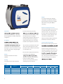
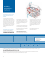
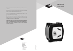
Kair
®
VENTILATION LIMITED
iECO 4 RANGE
Continuous Mechanical Supply and Extract
Ventilation with Heat Recovery
Appendix Q Eligible
Weight
As a result of the unique clamping
construction in combination with the
plastic/synthetic elements, the weight
of the heat recovery unit iECO 4 is
only 25 kg.
Exhaust and Supply Connections
All exhaust and supply connections have
an internal diameter of 150 mm and
Application
have the same design. The only
for all new build dwellings – especially
connections and motor modules. With
metal ducts accessories directly. Each
those being built to a higher standard of
units for houses, the air supply is
connection is stamped with an
air-tightness.
situated at the lower part of the unit. In
embossed indicator which shows both
units for apartments the air supply is
the direction and source of the air.
external 180 mm. The connections can
be used to attach modular plastic and
Description
situated at the upper part. The motor
module seals the opposite connection.
recovery unit. It has a sophisticated
Counter Flow Heat Exchanger
The unique heat exchanger is based on
The connections on both the lower part
recover up to 91% of the heat from the
of the unit and the upper part can be
characteristics of this heat exchanger is
discharge air. This recovered heat is used
used for air extract. Unused connections
that the incoming and outgoing air is
to pre-heat the fresh air being brought
are sealed with a cap.
moving via triangular canals. Thus each
in from outside.
canal is surrounded by canals in which
Because of the unique patented clamp
Models
construction of the iECO 4, the
The table below lists the models
available
enormous surface area to exchange
heat. This special construction is one of
optimised. Therefore, there will be no
the reasons why up to 91% thermal
internal or external leakage.
Housing
The unit can be easily reversed when
The units for houses and apartments
dwelling designs are mirrored.
Table 1
Type
Appliance
iECO 4/WWHW
Whole House Hard Wired
iECO 4/WHRF
Connections to the dwelling
Connections to atmosphere
Inlet and exhaust capacity
Exhaust
Inlet
Exhaust
Inlet
Standard
Max
Pressure
bottom + upper side
bottom
upper side
upper side
225 m 3/h
325 m 3/h
150Pa
3
bottom
upper side
upper side
225 m /h
325 m /h
150Pa
iECO 4/APHW
Apartment Hard Wired
upper side
upper side
upper side
upper side
225 m 3/h
325 m 3/h
150Pa
iECO 4/APRF
Apartment Radio Frequency
upper side
upper side
upper side
upper side
225 m 3/h
325 m 3/h
150Pa
2
Whole House Radio Frequency bottom + upper side
3
100% Summer Bypass Valve
Both the inside and the outside
The heat recovery unit has a Summer
temperature is measured inside the
bypass valve, which is completely
iECO 4 by two integral sensors.
•
Whilst the temperature is still
decreasing the exhaust fan will speed
up and the supply fan will slow down
integrated in the unit. The bypass valve
•
With extreme low temperatures the
diverts the air supply completely around
Frost Protection Device
the heat exchanger. This means the exit
To prevent the heat exchanger from
supply fan is turned off, the frost
air from the dwelling does not heat this
freezing, a unique mechanism is
protection device will be closed, but
fresh air.
standard in the iECO 4. This
the exhaust fan will keep on working
mechanism consists of a valve,
After approx. 1.5 hours, the air supply
integrated on the upper part of the unit.
fan will start at a minimum speed and
the frost protection valve will be opened
to check whether the danger of freezing
is gone. When the temperature rises, all
above mentioned steps will be carried
out in reverse order.
All the above procedures will be carried
out automatically.
Especially during summer nights this
bypass valve is desirable because the
outside temperature is often lower than
The automatic frost protection device
the temperature inside.
works as follows:
The fully automatic temperature
•
controller makes sure the bypass valve
extracts some air from the area in
being opened when:
•
•
•
which it is installed. The air is mixed
The inside temperature is higher than
required (not adjustable)
The valve is open (modulating) and
with the fresh air
•
At the same time the supply fan will
increase fan speed to keep the fresh
the outside temperature
air volume at the same level
•
Motors
The iECO 4 is provided with two
The inside temperature is higher than
The outside temperature is for a
Removing the Heat Exchanger
energy efficient DC motors. The
impellers have backward curved
When the temperature drops the
blades which help to keep it clean –
longer period > 19° C (period depends
supply fan will decrease fan speed
maximising the capacity of the supply
on the exact temperature)
variably until a minimum is reached
and extract fans.
3
Capacity Setting
absorbed and the heat exchanger will
In the connection unit of the iECO 4
become less dirty.
are two potentiometers which allow for
adjustment of both the low speed and
fresh air inlet and the heat exchanger.
high speed. The mid position is an
automatically calculated value between
low and high. The factory setting for
dwelling. It also prevents the heat
high position is 225 m 3/h. To ensure the
exchanger from becoming dirty.
potentiometer should not be touched
cleaned and replaced by the occupant
unless the required volumes cannot be
without the need to remove the
reached when room grilles are set in
front cover.
their fully open position.
Appendix Q Eligible
Filters
The iECO 4 has been tested at BRE and is
The iECO 4 has as standard two G3
product. This means that the test results
between the exhaust duct from the
which are available on
www.sap-appendixq.org.uk can be used
ensures that dust and grease are
4
to help improve SAP rating.
Installing
The heat recovery unit iECO 4 is
•
Exhaust duct from the dwelling min.
internal diam. 150 mm
Installation and User Manual
The installation and user manual are
delivered with the unit. Make sure to
types of dwellings, from small
•
Apply the provided sound insulating
apartments to larger houses. The unit
using the unit. If required the
dwelling, like:
•
In the loft, in a closed room
•
In a closed storage room
•
In an airing cupboard
read these manuals before installing or
•
D=180mmm L=500mm) between the
installation manual can be obtained
air supply to the dwelling and the unit
from Itho Ventilation Limited prior to
Condense drain with water seal,
delivery of the unit.
replenishable, for a water block
between the unit and the place
where the unit is mounted and the
waste pipe
Mounting
mounting bracket, to a wall with a mass
of no less than 200 kg/m 2 .
Points of Attention
To ensure a good installation please pay
attention to:
•
•
•
Mains supply must be 230V AC
Access to the Unit
The unit should be located so that it can
be easily accessed for servicing. To
heat exchanger there must be a space of
not less than 50 cm in front of the unit.
Moisture resistent insulated exhaust
duct to outside (min. internal diam.
Important
150 mm)
Make sure that nothing is placed on top
Damp proof thermal isolated fresh air
of the automatic frost protection valve.
inlet duct from outside (min. internal
diam. 150 mm)
As, when the valve opens a foreign
object falling in would prevent the
mechanism from working.
•
Air inlet duct to dwelling min. internal
diam. 150 mm, which can be split up
in two ducts internal diam. 150 mm
Easy access
5
Maintenance
Warranty
The maintenance of the unit involves
The unit has a guarantee period of 2
only the following:
years from date of installation.
•
completed.
RF 3 Speed Controller
Accessories
A heat recovery system consists of
building materials
•
about ducting and other system
RF 3 speed Control
components can be obtained from Kair
•
•
the iECO 4. More information
Ventilation Ltd.
Clean the heat exchanger every
six years
If the heat recovery unit is provided with
a wireless (radio frequency) remote
Electrical Connection
control switch. The receiver for the
The iECO 4 can be connected to a
•
Depending on the pollution, also clean
the motor and fan blade
during factory production. The switch,
attached to the unit as standard. When
installing the unit, a double pole
minimum contact gap of 3mm. Since
the unit is double insulated it does not
need to be earthed. As standard, the
electrical connection on the unit is
positioned on the left hand side. When
which has a self-adhesive backing,
should be located in the wet rooms;
most likely the kitchen or bathroom
within the house and can switch the
unit between speed position one, two
and three. Additional transmitters are
available to allow the fan to be
controlled from more rooms; the utility
installation the electrical connection will
room, en-suites etc.
be positioned on the right hand side.
The last used switch is the master.
Advantages of Wireless Control:
Spare parts can easily be exchanged,
without tools:
Control
•
The heat recovery unit iECO 4 can be
The heat exchanger can also be
reached by removing the front cover
•
The complete service module (motors,
•
•
Wired 3 step control
timer
Wired 3 way switch
disconnecting the ducts
This wired control unit can be connected
laptop with service software
6
Control from every room is possible.
•
Additional switches can be added at
any time.
•
A better indoor
climate, by
be removed or replaced without
Data can be read by connecting a
•
Wireless (RF) 3 step control unit with
fans, power supply and controls) can
•
is necessary.
ordered with a choice of optional control
units:
•
•
optimal
control.
to the connection box of the unit, see
wiring diagram.
Type RS3i built in
Installing RF Control Unit
To install the RF control switch unit in
•
switch the fan to high speed for 10
Pointing of transmitter towards the
minutes. Pressing the timer button a
fan is not necessary.
the kitchen, just adhere the control unit
on to a tile with the supplied double
sided adhesive tape. Alternatively, the
second time will switch the unit to high
•
No external antenna.
speed for 20 minutes and a third press of
•
Frequency 868 MHz, no licence
the button will switch the unit to high
speed for 30 minutes. The timer function
required.
screw. Each unit is supplied with an
can be over-ridden at any time by
installation and user manual. Do not
place the RF control switch on a metal
pressing either of the three speed
Timer Function
buttons.
A timer function is also included on the
surface.
RF control switch. This timer can be used
Additional RF Control Switch
to switch the ventilation to the highest
speed for a period of time, for instance
Information:
after an occupant has used the
•
Transmission range 100m in free air.
•
Transmission indoors is possible
the run-on period of the timer, the fan
through a maximum of 2
will revert back to its original speed.
bathroom. The advantage is that after
Pressing the timer button once will
Wiring Diagrams
iECO 4 -
With an RS3i Speed Controller
iECO 4 -
With a 3 way switch by others
7
Technical
Capacity
[m 3
Pressure
Power
Current
Voltage
Cos phi
Technical
Step 1 Min
50
10
Step 1 Low
75
20
10
0.07
230
0.63
98
14
0.094
230
0.65
98
Step 2 Medium
150
Step 2 Medium
150
40
39
0.32
230
0.53
96.2
80
45
0.37
230
0.54
96.2
Step 3 High
225
100
86
0.69
230
0.54
94
Step 3 High
225
150
100
0.79
230
0.55
94
Step 3 High
275
100
121
0.95
230
0.55
93
Step 3 High
275
150
139
1.09
230
0.55
93
Step 3 Max
325
100
172
1.32
230
0.56
92
Step 3 Max
235
150
200
1.45
230
0.58
92
* Values to be used in the EPC calculation at 230V, according to NEN5128.
Pow er s upply:
230V
Condens at e dis cha rge dia m et er:
4 0 m m ex t erna l
Frequency
50H z
Prot ect ion:
I P3 1
Dim ens ions :
height 8 4 8 m m
Filt ercla s s :
G3
width 730mm
depth 479mm
8
Technical
Specifications
Sound Power Spectrum
63Hz
Breakout
325 m 3/h / 150 Pa
3
22
125Hz
250Hz
500Hz
1000Hz
2000Hz
36
49
56
58
55
4000Hz
50
total
62
Breakout
275 m /h / 150 Pa
20
24
48
57
56
51
46
60
Breakout
225 m 3/h / 150 Pa
19
31
47
57
54
47
42
59
Breakout
150 m 3/h / 80 Pa
13
26
42
45
45
39
30
50
3
Breakout
75 m /h / 20 Pa
5
19
31
31
31
26
15
36
Exhaust
325 m 3/h / 150 Pa
41
43
55
54
51
44
30
59
Exhaust
275 m 3/h / 150 Pa
39
41
54
52
48
41
27
57
37
38
53
50
46
37
23
56
Exhaust
3
225 m /h / 150 Pa
3
Exhaust
150 m /h / 80 Pa
32
33
47
42
38
29
16
49
Exhaust
75 m 3/h / 20 Pa
28
26
27
22
19
12
15
33
325 m 3/h / 150 Pa
Inlet
Inlet
45
57
64
69
68
62
58
73
3
46
56
63
69
66
60
55
72
3
275 m /h / 150 Pa
Inlet
225 m /h / 150 Pa
48
55
63
69
64
58
52
71
Inlet
150 m 3/h / 80 Pa
45
50
55
57
52
46
39
61
40
40
40
38
36
30
19
46
75 m /h / 20 Pa
Capacity qv [dm3/s]
Power input [W]
Static pressure Pst [Pa]
Inlet
3
1 capacity min
2 capacity low
3 capacity middle
4 capacity high
5 capacity max
6 power min
7 power low
8 power middle
9 power high
10 power max
9
Dimensions
M irrored s us pens ion
168
168
Sus pens ion
30
420
30
180
300
480
10
5xø5mm
30
30
420
80
80
30
210
210
600
30
848
30
848
210
210
600
30
300
180
5xø5mm
480
11
Building
Regulations
The 2006 Edition of the UK Building
The system provides quiet, uninterrupted
Air, drawn into the property by the fan,
Regulations Approved Document F1:
extract ventilation from the dwelling,
is routed through an integral high
Means of Ventilation (applicable in
removing warm stale air via all of the
efficiency synthetic heat exchanger
England and Wales) details four clearly
“wet” rooms, creating a permanent air
where warmth from the extracted air
defined systems of ventilation to
path through the property from the “dry”
is transferred to the incoming fresh
dwellings. System 4 - Continuous
habitable rooms.
air, before it is supplied to the
mechanical supply and extract with heat
habitable rooms.
recovery(MVHR) is complied with by the
new iECO 4 RF ultra-high efficiency
whole house heat recovery ventilation
system.
System 4 - Continuous Mechanical
Supply & Extract with Heat Recovery
requires a “minimum high rate” in each
wet room to be achieved (kitchen 13 l/s
and both utilities and bathrooms 8 l/s
(sanitary only 6 l/s)).
In employing this type of system, there
is no need to install background
ventilators in the dwelling – an ideal
solution to “noisy” sites.
The “minimum low rate” is calculated by
taking the number of bedrooms in the
dwelling and applying the l/s value from
Table 1.1b. In addition, the rate should
be no less than 0.3 l/s per m2 of internal
floor area (all storeys) plus, for each
additional occupant over and above the
anticipated two for the first bedroom
and one for each of the others, a further
4 l/s must be added to the extract rate.
Also, there is an addition of an
allowance to be calculated for air
infiltration.
11
Building
Regulations System 4
CONTINUOUS MECHANICAL SUPPLY &
EXTRACT VENTILATION WITH HEAT
RECOVERY
A continuous balanced mechanical
central supply and extract system to be
storey dwellings: 0.04 x gross internal
is the greater step of 1 and 2 above. The
positioned in loft or cupboard space. An
volume of dwelling heated space (m 3 )
minimum individual room extract rates
integral heat exchanger recovers a large
for single storey dwellings: 0.06 x gross
should be at least those given in Table
percentage of heat energy that would
internal volume of dwelling heated
1.1A for minimum high rate. Minimum
have otherwise been lost. In employing
3
space (m ).
air supply rate should be at least the
this type of system, there is no need to
whole building ventilation rate in 1
install background ventilators in the
2. Calculate the whole dwelling extract
dwelling.
rate at maximum operation by adding
CONTINUOUS SUPPLY AND EXTRACT
above.
the individual room rates for ‘minimum
4. No background ventilators are
high rate’ from Table 1.1A.
required with System 4.
1. Determine the whole building
ventilation rate from Table 1.1B. Allow
follows: Maximum Extract Rate (boost)
Table 1.1 A
Room
Kitchen
Minimum Intermittent Extract Rate
Continuous Rate
Minimum high rate
Minimum low rate
Total extract rate
must be at least
the whole building
ventilation rate
in table 1.1B
30 l/s (adjacent to hob); or 60 l/s elsewhere
13 l/s
Utility Room
30 l/s
8 l/s
Bathroom
15 l/s
8 l/s
Sanitary Accommodation
6 l/s
Table 1.1 B
Whole Building Ventilation Rate (l/s)
Number of bedrooms in dwelling
1
2
3
4
5
13
17
21
25
29
Minimum value in any dwelling of 0.3 l/s per m 2 floor area
In addition, the minimum ventilation rate should not be less than 0.3 l/s per m 2 internal floor area (this includes each floor, e.g. for a
This is based on two occupants in the main bedroom and a single occupant in all other bedrooms. This should be used as the
default value. If a greater level of occupancy is expected, then add 4 l/s per occupant.
12
SAP
Appendix Q
Eligible
The iECO 4 is SAP Appendix Q Eligible
proving it to be one of the most energy
Designed to calculate the energy
performance of Dwellings, the Standard
Assessment Procedure (SAP) Appendix Q
website: www.sap-appendixq.org.uk is a
UK based Government led initiative used
to demonstrate compliance with
building regulations within the
following areas - Part L (England and
Wales), Section 6 (Scotland) and Part F
(Northern Ireland), providing energy
ratings for dwellings that can be
compared nationally. Here are the
relevant independent BRE test results for
the iECO 4:
As featured in the Energy Saving Trusts’
iECO 4, a credit to continued
and to aspire to go that extra mile.
‘Demonstrating Compliance - Best
technological advancements.
Following years of experience in having
Practice’, in order to meet reduced CO2
to meet continually tightening
emission targets, MVHR units have been
The Energy Saving Trust’s ‘Best Practice’
set certain standards and must have a
standards, along with The Code for
demands, we always aims to stay one
ventilation solutions that exceed current
guidance toward sustainable home
both reached and exceeded by the
expectations.
chance to exceed Government targets
13
Kair Ven la on Limited established in 1997 offers a unique range of products that provide
solu ons to every conceivable damp related problem from preven on to eradica on. We
manufacture products and equipment proven to be able to totally eradicate dampness,
condensa on and mould growth from buildings.
Our innova ve products include Energy Saving Heat Recovery ven la on systems which are
the most cost effec ve way to totally eradicate condensa on and mould growth problems
from buildings. The systems work no ma er how severe the problem, how complex the
design lay out, how densely populated the dwelling or how varied the lifestyle of the
occupants. They also provide a health dividend in that they produce a con nuous drying out
process and create drama c improvements in the quality of the internal air supply.
Kair Ven la on Limited offer customised and ‘off the shelf’ ven la on solu ons, which are
simple to install and use energy with unparalleled efficiency.
Anywhere in the world where you need venlaon or suffer from damp and condensaon
Kair has the answer. Kair provide comprehensive domes c, commercial, light industrial
solu ons for dampness & rot, condensa on & mould along with electric hea ng product
ranges – backed up by service and support that you can count on.
Kair
®
iECO 4 RANGE
powered by Itho
Kair Ventilation Ltd.
Unit 6, Chiltonian Ind Est,
Manor Lane,
Lee,
London,
SE12 0TX
Available from:
Kair
VENTILATION LIMITED
®
Tel: 08451 66 22 40
Fax: 08451 66 22 50
E-mail: [email protected]
Web: www.kair.co.uk