1
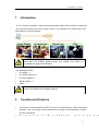
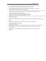
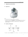
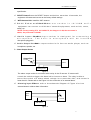
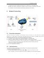
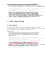
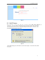
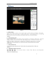
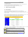
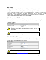
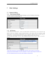
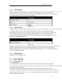
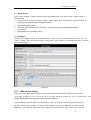
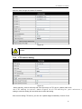
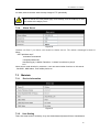
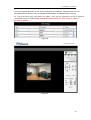
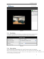
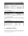
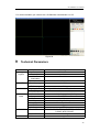
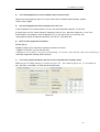
B Series——Astro Boy Model IP Camera 2010-3 V2.3 User Manual IP CAMERA User Manual Index 1 INTRODUCTION......................................................................................................................... 4 2 FUNCTION AND FEATURES.................................................................................................... 4 3 APPEARANCE AND INTERFACE............................................................................................ 6 3.1 APPEARANCE.................................................................................................................................. 6 3.2 INTERFACE OF EQUIPMENT............................................................................................................. 6 4 NETWORK CONNECTING......................................................................................................... 8 4.1 CONNECTION INSTRUCTION............................................................................................................. 8 4.2 VISIT INSTRUCTION......................................................................................................................... 8 5 VISIT IP CAMERA FROM LAN................................................................................................ 9 5.1 SET IP ADDRESS......................................................................................................................... 9 5.2 VISIT IP CAMERA......................................................................................................................... 11 6 VISIT IP CAMERA FROM WAN................................................................................................ 13 6.1 PORT FORWARDING......................................................................................................................... 13 6.2 DDNS...................................................................................................................................... 14 6.2.1 Manufacturer’s DDNS......................................................................................................... 14 6.2.2 Third Party DDNS............................................................................................................. 14 7 OTHER SETTINGS..................................................................................................................... 15 7.1 NETWORK SETTING......................................................................................................................... 15 7.1.1 Basic Network Setting......................................................................................................... 15 7.1.2 WIFI Setting..................................................................................................................... 15 7.1.3 ADSL Setting..................................................................................................................... 16 7.1.4 UPnP Setting..................................................................................................................... 16 7.1.5 DDNS Setting..................................................................................................................... 16 7.2 ALARM SETTINGS......................................................................................................................... 16 7.2.1 Alarm Setting..................................................................................................................... 16 7.2.2 Mail Service Setting............................................................................................................. 17 7.2.3 FTP Service Setting............................................................................................................. 18 7.2.4 Alarm Server..................................................................................................................... 19 7.3 MAINTAIN...................................................................................................................................... 19 7.3.1 Device Information............................................................................................................. 19 7.3.2 User Setting......................................................................................................................... 19 7.3.3 Time Setting......................................................................................................................... 21 7.3.4 Other settings..................................................................................................................... 21 7.3.5 Firmware upgrade ............................................................................................................. 22 7.3.6 Restore Factory Default .................................................................................................... 22 2 IP CAMERA User Manual 7.3.7 User browsing Log............................................................................................................. 22 8 CENTRALIZATION CONTROL................................................................................................ 22 9 TECHNICAL PARAMETERS.................................................................................................... 23 10 FAQ.............................................................................................................................................. 24 3 IP CAMERA User Manual 1 Introduction The IP Camera combines a high quality digital video camera with network connectivity and a powerful web server to bring clear video to your desktop from anywhere on your local network or over the Internet. Your IP Camera package should contain the following items, If any of the listed items are missing, please contact your reseller from where you purchased the camera for assistance. The package includes: IP Camera * 1 IP Camera Utility CD *1 5V Power Adapter *1 Stand of plastic * 1 Cable * 1 If you need the device with wifi function, please choose the model of /W, it has built-in wifi module and transmitting antenna. 2 Function and Features The video is compressed by MJPEG. There are VGA/QVGA two video resolutions optional. User can change some parameters according to their demands to satisfy his own visual prefer. W i t h b u i l t - i n M i c r o p h o n e , a n d a l s o 4 p r IP CAMERA User Manual mic , it enables user to monitor the sound on the site. User can also connect this equipment to the speaker, and it supports two-way intercom function. It was equipped with pan/tilt function, horizontally 350°and vertically 70°. Its outlook is smart, easy and convenient to install in many sites. It adopt s the TCP/IP network protocols and has inner web server. browse video through IE and other browsers. Data is transferred through one port; it is easy for user to do the network setting. Support 802.11b/g protocol, can build up wireless monitoring. Supports UPNP, port forwarding automatically on the router. Motion detection and alarm pin can be connected to external sensors to de environmental situation. Alarming record can be stored by email, FTP server. External alarm can be open w h e n d e t e c t i n g u n u s u a l i t y . I t a l s o server. Infrared LED for night vision covers 5m area, to realize 24 hours monitoring. Support three level of user authority. Support upgrading online. Ma nu fac ture att ach ed a l ab el at th e b ott om of e ac h I P Cam era, it i nc lud e De vice ID, DDNS. When IP Camera is connected to the internet, this URL can be used to visit the device. Manufacture provides free software, support Multi-view, Long time recording, video replay etc. 5 IP CAMERA User Manual 3 Appearance and interface 3.1 Appearance Figure 1 Note : Power Indicator: it will turn RED if equipment was powered on. Status Indicator: Slow ( fol ni cek e p re r 2 s e c )o n , dindicates the device is s e a r c h i n g f o r n e t w o r k ; (f l i cokneer o r t w i c e p e r s e c)o n, di n d i c a t e s t h e w i r e d network connected; Frequent flicker ( 2~3 times per second) , indicates wireless network connected. 3.2 Interface of Equipment Figure 2 1 ) Power Input SCoocnkneet c: t DC adaptor, its output should 6 be 5 IP CAMERA User Manual specification. 2 ) RESET Button:Press the RESET button and hold on more than 10 seconds, the equipment will restart and recover to the factory default settings. 3 ) WIFI Antenna Hole: Install the WIFI antenna. 4 ) R J 4 5 E t h e r n e tR S J 4o 5c kEe t t h: e r n e t s o c k e t i s 1 0 / 1 0 0 M s e l f e q u i p m e n t c a n c o n n e c t t o a l l k i n d s o f n e t w o r k e q u i p m e n t s , s u c h a s h u b , r o u t e r, switch, etc. NOTE: Factory setting IP is 192.168.0.178, the http port is 80, the username is admin, the password is 123456. 5 ) Audio Input SA o cu kd ei ot : i n p u t s o c k e t i s d e s i g n e d f o r c o n n e c t i n g m i c r o p h o n e . T h e b u i l t - i n m i c r o p h o n e w i l l b e i n v a l i d microphone plugged in. 6 ) A u d i o O u t p u t S o cA ku ed t :i o o u t p u t s o c k e t i s f o r l i n e - o u t a u d i o p l a y e r , s u c h a s headphone, speaker, etc. 7 ) Alarm Output Socket Output Switch Pins Alarm Alarm power Figure 3 The alarm output socket is connected with a relay in the IP camera. IP camera will control the switch to trigger the alarm bell or buzzer to alarm. The relay is able to c o n t r o l t h e s w i t c h o f a a l a r m w h o s e v o l t a g e i s n o m o r e t h a n 3 6 V, a n d c u r r e n t i s lower than 2A. Please refer to the Figure 3 for the connection of an external alarm. 8 ) A l a r m i n g I n p u t P iPnl :e a s e r e f e r t o t h e s c h e m a t i c D i a g r a m o f F i g u r e 4 f o r h o w external detector collects alarm information. Input pins PIR Switch PIR Power Figure 4 7 IP CAMERA User Manual The detector should be switched type (always on or always off). If the detector has detected the smoke or people or animal to enter the area, the detector will switch on or switch off. And it will send the external alarm signal into the IP camera. 4 Network Connecting Figure 5 4.1 Connection Instruction Before visit the IP Camera, you should firstly connect it to the Network, supp power to it, and check if the light of RJ45 Socket is normal to make sure all of communication links are fluent. The connection method is like as Figure 5. 1) IP Camera-1 and IP Camera-2 are connected separately to 2 different LANs. 2) And these 2 LANs are already connected to the Internet. In order to get the LANs to be connected to the Internet, they are required to be equipped with router and to apply for the communication link from the local Internet Service Provider (ISP) and connect to it by ADSL or optical fiber, etc. 3) PC-3 is connected to the Internet. 4.2 Visit Instruction To visit the IP Camera, you should do some settings of IP Camera and Internet besides getting the communication link fluency. 1) The PC and IP Camera are in the same LAN. If you want to use this PC to visit the IP Camera, you need to make sure their IP address is at the same segment. 8 IP CAMERA User Manual 2) Otherwise you need to do the reset of the IP Camera’s IP address. For example, the IP Camera-1’s IP address in Figure 5 is 192.168.1.139 (at the segmen 192.168.1), while the PC-1’s IP address is 192.168.0.175 (at th 192.168.0), then you will be not able to visit the IP Camera through the PC-1. You need to change the IP Camera-1’s IP address to 192.168.0.139 firstly. The PC and IP Camera are in different LANs, but they are all connected to Internet. For the IP Camera-1 and PC-2 in Figure 5, if you want to visit IP Camera1 by PC-2, you should firstly do the setting as 1) to make sure that you can visit IP Camera-1 through PC-1 and then do the setting of router-1 (do the port forwarding from th e ro ute r). Th e PC-2’s vis it app lic at ion co ul d b e s ent thro ug h ro ute r-1 to IP Camera-1. Normally, PC-2 could only send the information to router-1, if you don’t do the setting of router-1, then PC-2 could not visit IP Camera-1. 5 Visit IP Camera from LAN 5.1 Set IP Address The IP addresses of IP Camera and PC should be at the same segment, for Figure 5, the IP Camera-1 can’t be visited. Run the BSearch_en.exe in the CD, click Se button, and then select the IP Camera-1 to reset the IP address, as the Figure 6. Setting Instruction: Please carefully check the “Local PC information” on the top left corner which lists the PC configuration. If there are several network adapters in the PC, please select the one you are using and make sure the IP address of IP Camera is as the same segment of the PC. Change the content of “IP config” on the right to make sure the content is the same as “Local PC information”. Only the last section of the IP address which ne setting by yourself, you can set it as 139 just like Figure 6. If you don’t know how to fill out the content of “IP config”, you could also tick the “Set IP automatically” to get the IP address from the router automatically. Put the user name and password into “Authentication”By ( default, the user name is: admin, password is: 123456 ). Click “Update”. The setting will take effect now. Select the device in list box, click “Browse” button, it will op automatically and pop up a window at the same time which requires to inputting the user name and password. Then you see the home page of the IP Camera-1, click “English” on the right-top corner, just as below Figure 7. 9 IP CAMERA User Manual Figure 6 If you have the firewall software in your PC, when you run the HSearch_en.exe, it may pop up a window to say if you want to block this program or not, then you should choose not to block. IP Camera by default use fixed IP address 192.168.0.178 and fixed http port 80. If you don’t have this software, you could also press down the reset button to go back the factory setting. Then you could use this defaulted IP address to visit the IP Camera. 10 IP CAMERA User Manual Figure 7 5.2 Visit IP Camera W e s u g g e s t u s i n g I E k e r n e l b r o w s e r ( t oi t v ci ea w n pt hr o e v vi di de e m o ore functions ) , but user need to install Player before viewing the video. Click “download and install player (first use)” link, it will popup dialogue box as Figure 8, click Run, it will automatically download player and install. Figure 8 After install the plug-ins, click “Mode 1 to view” link in Figure 7 to view the video (video as Figure 9). 11 IP CAMERA User Manual Figure 9 1 ) Menu column There are 2 kinds of menu, one is main menu, and the other is submenu. The main menu lies at the top of the interface, including View, Networ Submenu lies on the left of the interface, and different main menu is in line with different submenu. 2 ) Video Displaying Area Video display area is according with resolution, the higher resolution, and the display. Double click left mouse in the video display area, it will show full screen, and double click again, it will go back to original size. Double click right mouse in the video display area, it will show green icon, click the left mouse, Pan/tilt will remote according to arrow signs. 3 ) Alarm indicator area Up-right side is alarm indicator area, if device alarm, the green light will be in Red, and alarming. 4 ) Speaking and Video Control Area Icons are as follow: A u d i o , Ta l k , R e c o r d , a n d S n a p s h o t Click icons for related functions. 12 IP CAMERA User Manual 5 ) PTZ and video control In Pan/ Tilt co ntro l a rea, us er c an co ntro l th e p os iti on acc ord in g to the arro w si gn : up , down, left, right, middle, horizontal cruise, vertical cruise, and stop. User can also set the device resolution, brightness, contrast and other parameters. 6 Visit IP Camera from WAN 6.1 Port forwarding Follow the “Visit IP Camera from LAN” steps; make sure PC-1 can visit IP Camera-1. In Figure 5, before the computers in WAN (PC-2, PC-3) can visit the IP Camera-1, must p u t t h e I P C a m e r a - 1 i n t o W A N . Yo u c a n s e t p o r t f o r w a r d i n g o n R o u t e r - 1 t o p Camera-1 into WAN. Open the Router Setting interface on PC-1. The interfaces for different rou different, and the port forwarding settings are different, please refer the router manual to set. For most routers, “Virtual server” option can be found in setting interface. Fill the IP address and port of IP Camera-1 into corresponding blank. Figure 10 is an example. Figure 10 Select “status” option and remember the WAN IP address, enter the IP addr browser of PC-1, if IP Camra-1 can be visited via PC-1, the port forwarding is success. And PC-2 and PC-3 can also visit the IP Camera-1. WAN IP address is allotted by ISP, please make sure it’s an available WAN IP address. As WAN IP address is lack, many WAN IP address are available in limited area. If PC-2 and PC-3 are not in this area, the IP Camera-1 won’t be visited by them. If user wants to put several IP Cameras into WAN, every device should set the port forwarding. In order to distinguish these devices, every device should set a different port. If the port of the device is not 80, should add the port to IP address with colon to visit the IP Camera. Example: http://202.96.82.177:81. 13 IP CAMERA User Manual 6.2 DDNS In Figure 5, Router-1 get WAN IP address via ADSL, these WAN IP address is always changing, so, the IP address can’t be confirmed when visit the device in WAN. We need the dynamic domain name server (DDNS). IP Camera-1 send IP configuration to DDNS every few time, DDNS can recognize the WAN IP address of the rout connected with IP Camera-1. The WAN IP address can be searched on D d o ma i n n a m e . He r e i n , d o m a i n n a m e s u b s t i t u t e t h e d y n a m i c I P a d d r e s s . I f t h e d e vi ce can’t be visited by IP address, this domain name is also unavailable. 6.2.1 Manufacturer’s DDNS Device manufacturer has established a DDNS, and allotted a dynamic domain name to every device, the domain name has been integrated into devices when producing. For e x a m p l e , e n t e r d o m a i n n a m e o f F i g u r e 11 , t h e b r o w s e r w i l l c o n n e c t t h e d e v i c e display the IP address. Figure 11 The domain name is realized by forward manner, the domain name will change into the IP address and port number of the device when visit by domain name. If the device can be visited by IP address but can’t be visited by manufacturer’s domain name, please check the DNS info is available or not and make sure the DNS setting is the same with the DNS setting of PC in LAN. 6.2.2 Third Party DDNS User can also use third part DDNS, such www.3322.org as . User should apply a free domain name from this website and fill the info into the below blanks (Figure 12) and save the settings. Then the domain name can be used. Figure 12 The third party domain name is realized by analysis manner, the domain name will be displayed in the browser all the time when visit camera. If the port is not 80, the port number should be adding to the domain name with colon. Example: http://robbicam2.3322.org:81 14 IP CAMERA User Manual 7 Other Settings 7.1 Network Setting 7.1.1 Basic Network Setting The user can also enter the Basic Network Settings to set the IP address except using the search software. See below Figure 13. Figure 13 7.1.2 WIFI Setting If the device is with WIFI, enter the Wireless LAN Setting, just as below Fig shown, click the “Search” button several times, it will show you the wireless netw detected in the Wireless Network List column. Select one of them and t Wireless Lan”, then the relevant data of the selected wireless network will be shown in the following blanks. Put in the password and click “Set”, then the WIFI finished. Figure 14 Note: When the device is connected both WIFI and wired, after it starts up, it will firstly connect to the wired network, if it can’t connect to it, then it will change to connect the wifi. The IP address and port is the same, either wireless or wired network. 15 IP CAMERA User Manual 7.1.3 ADSL Setting U s e r c o u l d e n a b l e t h e A D S L D i a l u p a c c o r d i n g t o Telecom Operators will assign the user name and password to you when you apply for ADSL service.) Connect the device directly to the ADSL modem and it is connected to the Internet, but don’t need to do the port forwarding. t h e Figure 15 7.1.4 UPnP Setting U P N P s t a n d s f o r u n i v e r s a l p l u g a n d p l a y, i f y o u s t a r t U P N P, o n c e t h e I P c a m e r a connected into the LAN, it will communicate with the router in the LAN automatically. It will request the router to open a port to forward its own port. It is no need for the users to log in the router to set the port forwarding. Below Figure 16, tick “Using UpnP to Map Port” and the setting are completed. You could check the UpnP succeeds or not in the interface of System Maintenance. Figure 16 B e f o r e u s i n g UP N P f u n c t i o n , p l e a s e m a k e s u r e t h e r o u t e r ’s U P N P f u n c t i o n h a s b e e n triggered. Because there are so many different routers, and not all of them can support UPNP. Please test if the router work well with the equipment, if not, we would suggest you don’t enable this function. 7.1.5 DDNS Setting Please refer to the content in 6.2. 7.2 Alarm Settings 7.2.1 Alarm Setting 1 ) Alarm Detect User can select the motion detect to enable monitor a certain area, if anything happens i n t h a t a r e a , i t w i l l t r i g g e r t h e a l a r m . I n t h e m o t i o n d e t e c t s e n s i b i l i t y, t h e s m a l l e figure, the more sensitive it is. As showed in picture 4, if external alarm detector was connected to the device, user will be able to tick the scheduler for alarm. If the external alarm detector is an always on switch alarm. Please choose “open”. If the external alarm detector is always off switch alarm, please choose “close”. 16 IP CAMERA User Manual 2 ) Alarm Action After every trigger of alarm during the scheduled time, the device can trigger alarm in several ways. IO i n t e rf a c e f o r a l a rm s i g n al o u tp u t : w h en r el a y wa s s wi t c h ed o n (p l e a se r e fe r t o Picture 3), the external alarm will begin to alarm. Send alarm info by email. Send the site pictures to the FTP server, user can also set the break time between two pictures. Send alarm info to the alarm server. 3 ) Scheduler De vic e wi ll t rigg er a la rm i n s ch edu le d ti me . Use r ca n s et sc hed ul e ti me to b e “a ll the time”. Please set the system time, time zone, and select the scheduled time. Please refer to the Picture 17. Figure 17 7.2.2 Mail Service Setting The device will send alarm email to the email address was filled in. Please do the mail settings properly fist, Picture 18 is a mail setting page for your reference. Aft setting, please click save and test to check if it works properly. If have already set the mail server properly, user can tick to enable “Report Internet IP by mail”. After every restart, the device will send its Internet IP address to user’s email address. If this device has been port mapping to the Internet, then users can view the 17 IP CAMERA User Manual device’s video through the Internet IP address. Figure 18 Please make sure your email server open POP3 functions, or the mail can’t be sent. 7.2.3 FTP Service Setting Figure 19 When alarming, device will snap and send the image to FTP server, please make sure the FTP setting is correct. Above Figure 19 of FTP setting for your reference, setting to store the setting info and click test to check the setting. After correct setting FTP server, you can use “upload Image Periodically” function. Even 18 IP CAMERA User Manual no alarm, device can also send the snap image to FTP periodically. In order to use FTP function, user should apply username and password on the FTP server first. And please apply some storage, and the authority to write and create sub-category into it. 7.2.4 Alarm Server Figure 20 Pl e a se c on f i rm i f y o u h a v e c o n n e c te d t o a l a rm s e rv e r. T h e a la r m m e s s a g e fo r ma t a s follow: GET /api/alarm.asp ? username=username& userpwd=password& rea=alarm type (1=Motion Detection, 2 =Alarm from Alarm in port)& io=0 Alarm server need develop by customer , user can extend other functions on this server , like SMS , MMS alarm , and mobile phone etc . 7.3 7.3.1 Maintain Device Information Figure 21 7.3.2 User Setting There are three levels of authority; they are Administrator/Operator/Visitor. Administrator 19 IP CAMERA User Manual have the highest authority, it can do any change to the settings. Operator account only can operate the IP camera, can’t do changes to the settings, and please refers to Figure 23. Visitor account only can watch the video, can’t do any operation to the IP camera, and please refers to Figure 24.By default, the administrator’s user name is admin, password: 123456. Figure 22 Figure 23 20 IP CAMERA User Manual Figure 24 7.3.3 Time Setting If the device is connected to the Internet, you enable the NTP server to correct the time and select the right time zone. Or you should use the PC’s time to correct its time. Figure 25 7.3.4 Other settings You can choose open or close indicator LED. If set PTZ center on start ‘Yes’, when start device, Pan/Tilt will move to center and then stop. You can also set the Horizon patrol rounds and vertical patrol rounds, when you click patrol on the ‘view’ interface, it w round according to your setting rounds. 21 IP CAMERA User Manual Figure 26 7.3.5 Firmware upgrade The device runs 2 kinds of programmer, one is system firmware, the other is application firmware. They could be upgraded separately. Figure 27 7.3.6 Restore Factory Default Click “Restore Factory Default”, it will pop up a dialogue to confirm if you really want to restore the factory default. After confirmation, the system will restore the factory default and reboot. 7.3.7 User browsing Log After enter the log interface, you could view who and when the device is visited. Figure 28 8 Centralization Control IPCMonitor is a free software offered by factory, several devices on LAN and WAN can be browsed at the same time. The software also supports snap, video record, alarm and so on. The below Figure 29 is the interface. 22 IP CAMERA User Manual For more information, pls. refer to the <<IPCMonitor User Manual>> in CD. Figure 29 9 Technical Parameters Item Image Capture Pan/Tilt Sub Item Sensor Total of pixel Minimum illumination Lens Pan Coverage f=4.5mm, F=2.0, Fixed Iris 350° Assistant Tilt Coverage Lighting Control 70° 8pcs 850nm Infrared LEDs, 5m distance Lighting Auto control Resolution Compression Frame rate Bit rate Image Rotation OSD Audio Compression Basic Protocol Other Protocol 640*480(VGA)/320*240(QVGA) MJPEG 30fps 128kbps ~ 5Mbps Mirror /Up-side down support ADPCM TCP/IP、UDP/IP、HTTP、SMTP、FTP、DHCP、DDNS 、 UPNP、 NTP、 PPPOE 802.11b/g Video control support Video and Audio Network Other Description 1/4" CMOS sensor 300k IR on, 0 Lux 23 IP CAMERA User Manual Features Hardware Interface Physical Index Software(PC Side) Dual way audio Motion Detection Triggered Actions User Setting Date/ Time Setting Upgrade support support Email/FTP/external alarm/send message to alarm server Three levels support Upgrade from network DDNS Ethernet A free DDNS provided by manufacturer 10Base-T/100base-TX Alarm In Alarm Out Audio In 1 way 1 way Internal Mic and External Mic interface Audio Out Weight Main body Power Power consumption Operating temperature Operating temperature OS Supported Audio Line-out interface x 1 343g 111mm(L)*107mm(W)*148mm(H) DC 5V <6W 0℃~ 45℃ Browser Application Software 10 1) 10% ~ 80% non-condensing Microsoft Windows 98/2000/XP/Vista Internet Explorer6.0 and Above or Compatible Browser, Firefox etc. IPCMonitor FAQ Unmatched power adapter will damage the equipment or power adapter When plug in the power adapter , please check carefully the voltage , it should be 5V adapter for this equipment. 2) Slowly browse speed This equipment adopts MJEPG compression format, it needs large network bandwidth, the narrow bandwidth will affect the browse speed . The typical bandwidth uses situation as below: 640x480@10fps : 4.0 Megabits ~ 5.0 Megabits 320x240@30fps : 1.2 Megabits ~ 1.6 Megabits 3) Color difference The default is infrared lens, when visit outdoor or strong infrared light scenes, there are color differences, the color is not accordance to the real scenes. User can change it to color lens to solve this problem, but color lens can only use under the daylight situation. 24 IP CAMERA User Manual 4) Can’t find equipment via search software after connect to LAN Make sure the equipment and PC is in the same LAN; if install firewall software, please close it and try again. 5) Can find equipment via search software, but can’t visit If the IP address of IP camera and PC is not in the same Network Segment, you should change them on the same Network Segment before visit. Network Segment is the first three number of IP address. If the IP address of PC is 192.168.0.100, so it can only visit the equipment which IP address is between 192.168.0.1~192.168.0.255. 6) Can’t visit the equipment via Internet Please refer to: Chapter 4 (Figure 3) to check if the internet connection is correct; Chapter 5 to check if you can visit via LAN; Chapter 6 to check if the port forwarding is correct; and check the route setting i forbid this equipment sending data to internet. 7) Can visit via public IP address, but can’t visit via manufacturer’s domain name Make sure the DNS setting is same as your PC , as below Figure 30 , in the search tool , the DNS 1 and DNS 2 on both side should be same. Figure 30 25