1
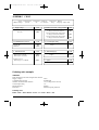
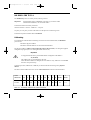
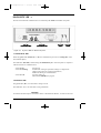
EMA.Chapitre1-CE.v2.1
6/11/00
8:58
Page i
Eurotherm Monitoring
and Acquisition unit
EMA
RMS current and voltage measurement
with digital communications
User manual
© Copyright Eurotherm Automation 1999
All rights reserved. All reproduction or transmission in any form whatsoever and using any procedure (electronic or
mechanical, including photocopying and recording) without written permission from Eurotherm is strictly prohibited.
EUROTHERM AUTOMATION has taken particular care to ensure that these specifications are correct. However, in order
to maintain our ‘leading edge’ we continually strive to improve our products, which may lead to modifications or
omissions in the specifications.
We shall not be held responsible for any damage, injury, losses or expenses incurred as a result of such modifications.
Ref.: HA 176140 ENG - Issue 2.1 - Printed in France
07/2000
i
EMA.Chapitre1-CE.v2.1
ii
6/11/00
8:58
Page ii
EMA User Manual
EMA.Chapitre1-CE.v2.1
6/11/00
8:58
Page iii
EMA USER MANUAL
CONTENTS
P age
Applicable European Directives
. . . . . . . . . . . . . . . . . . .iv
1.
Identification of the monitoring unit . . . . . . . . . . . .1-1
2.
Installation . . . . . . . . . . . . . . . . . . . . . . . . . . . . . .2-1
3.
Digital Communication
4.
Configuration and display . . . . . . . . . . . . . . . . . . .4-1
. . . . . . . . . . . . . . . . . . . . .3-1
Eurotherm address . . . . . . . . . . . . . . . . . . . . . . . . . .4-16
For a detailed description of the digital communications used by EMA units,
(Profibus DP and Modbus® protocols), see the manual
‘EMA Digital Communication’
EMA User Manual
ref.: HA
176197 ENG - issue 2.0
iii
EMA.Chapitre1-CE.v2.1
APPLICABLE
6/11/00
8:58
Page iv
EUROPEAN DIRECTIVES
CE marking and safety
EMA products installed and used in compliance with this user manual meet the essential
requirements of the European Low Voltage Directive 73/23 EEC dated 19 February 1973
(modified by Directive 93/68 EEC dated 22 July 1993).
ELECTROMAGNETIC COMP ATIBILITY (EMC)
Electromagnetic compatibility is defined for industrial environments only, not for domestic
environments.
EMA products installed and used in compliance with this user manual are certified
compliant with the following EMC test standards. A system incorporating these products
may be certified compliant with the EMC Directive as far as EMA products are concerned.
Test standards
Test
EMC test standard
Immunity
Generic standard
Electrostatic discharge
Fast transients
Electromagnetic fields
Radio frequencies in common mode
EN50082-2
EN 61000-4-2
(06/1995)
EN 61000-4-4
(01/1995)
EN 61000-4-3 and ENV 50204
EN 61000-4-6
Emission
Generic standard
Radiated and conducted
EN 50081-2
EN 55011 Class A
iv
(1991)
EMA User Manual
EMA.Chapitre1-CE.v2.1
6/11/00
8:58
Page v
Declaration of conformity
Availability
A declaration of CE conformity is available on request.
Validation by competent body
Eurotherm Automation has validated the compliance of EMA products with the European
Low Voltage Directive and EMC test standards through product design and laboratory
testing.
The tests performed on EMA products are listed in a Technical Construction File
validated by the LCIE (Laboratoire Central des Industries Électriques), a recognised
competent body.
EMC guide
In order to help you reduce the effects of electromagnetic interference associated with the
installation of the product, Eurotherm Automation can supply you with an
‘Electromagnetic Compatibility’guide (Ref. HA 025464).
This guide lists best practices generally applied for EMC.
EMA User Manual
v
EMA.Chapitre1-CE.v2.1
6/11/00
8:58
Page vi
PRECAUTIONS
Important precautions and specific information are indicated in the manual by two symbols:
This symbol means that failure to take note of the information may have serious
consequences for the safety of personnel and may even lead to electrocution.
Danger!
This symbol means that failure to take note of the information may have serious
consequences for the facility or may lead to incorrect operation.
Caution!
These symbols attract the reader’s attention to specific points. However the whole of the manual
remains applicable.
Personnel
The unit must only be installed, configured, commissioned and maintained by qualified staff
authorised to work on low voltage electrical industrial facilities.
Independent alar
m
It is the user’s responsibility to fit an independent safety mechanism which must be inspected
regularly. This is highly recommended g iven the value of the equipment controlled by the
monitoring unit. These alarms must be inspected regularly.
Eurotherm can supply appropriate devices.
Further information
For any further information or if in doubt please contact your local Eurotherm office where qualified
staff are available to advise you or assist with commissioning your facility.
vi
EMA User Manual
EMA.Chapitre1-CE.v2.1
6/11/00
8:58
Page 1-1
Chapter 1
IDENTIFICATION OF
Contents
THE MONITORING UNIT
Page
General presentation . . . . . . . . . . . . . . . . . . . . . . . . . . . . . . . . . . . . . . . . . . . . .1-2
Technical specifications . . . . . . . . . . . . . . . . . . . . . . . . . . . . . . . . . . . . . . . . . . .1-4
Ordering code . . . . . . . . . . . . . . . . . . . . . . . . . . . . . . . . . . . . . . . . . . . . . . . . . .1-6
Example ordering code . . . . . . . . . . . . . . . . . . . . . . . . . . . . . . . . . . . . . . . . . . . .1-6
EMA User Manual
1-1
EMA.Chapitre1-CE.v2.1
6/11/00
8:58
Page 1-2
GENERAL PRESENT ATION
The EMA monitoring and acquisition unit is designed to measure rms currents and voltages such as
those found on loads controlled by thyristor units with the following firing modes:
• firing angle variation (‘Phase angle’ mode, see specifications for details)
• supply voltage modulation (‘Burst firing’ mode)
• supply voltage modulation with a single firing period and one or a half cycle of non-firing
(‘Single-cycle’ and ‘Advanced single-cycle’ modes).
The measurements are available:
• on the unit’s front panel display,
• remotely, via the digital communication bus.
Depending on the model, a maximum of 5 voltage measurements and 5 current measurements are
possible.
The following features are located on the front panel:
• a two-line by 16 character LCD display,
• a female DB9 connector for configuration by PC, using the RS232 standard,
• diagnostic LEDs indicating communication operation,
• a button for scrolling through the display measurements (measurements, alarms,
identification).
The display enables the user to read the measurements and quickly diagnose the state of the unit.
A space is provided to enable the user to affix an identification tag.
The following features are located on the rear panel:
• plug-in connectors for measurement signals, power supply and digital communications.
• mini-switches for configuring bus termination resistors.
The EMA unit measures to an accuracy of ±(0.5% of the measurement ±0.1% of full scale):
• rms currents in the range 0.01 A to 1.1 A or 0.05 A to 5.5 A,
• rms voltages from 5 V to 550 V.
For values exceeding 110% of the full scale , the measurement will necessarily be false as the unit
clips the signal and displays the maximum value of the measurement range.
For each channel, alarms are signalled on the display and via the digital communication if the upper
or lower thresholds are exceeded.
If the EMA unit is to be reconfigured by the customer, configuration software is required. This
software, supplied as standard on 31/2” disks, operates on a PC running Windows 95, 98 or NT.
1-2
EMA User Manual
EMA.Chapitre1-CE.v2.1
6/11/00
8:58
Page 1-3
Figure 1-1 Overview of EMA monitoring unit
EMA User Manual
1-3
EMA.Chapitre1-CE.v2.1
6/11/00
8:58
Page 1-4
SPECIFICATIONS
Inputs
RMS current
Max. instantaneous peak cur rent
RMS voltage
Number of measurement channels
Measurements
Current
Voltage
Intrinsic precision
Frequency of signals measured
Integration time (filtering)
Power supply
Mains supply
Consumption
Protection
Local display
Monitoring unit
Measurement channel
Digital communication
Protocol
Transmission speed
Bus
Diagnostics
1-4
1 A rating: 0.01 to 1.1 A 5 A rating: 0.05 to 5.5 A
1 A rating: ±1.6 A
5 A rating: ±8.0 A
5 V to 550 V with peak voltage range ±800 V
Up to 10 measurements
Modularity by pairs of voltage/current measurements:
5 current and 5 voltage measurement channels
Display scale configurable from 1 A to 20,000 A
(direct reading with external current transformer).
Autoranging
In burst firing, advanced single-cycle or phase angle modes with
a thyristor firing angle ≥ 25°:
± (0.5% of measurement ± 0.1% of full scale)
the voltage scales are: 35 V (V < 35 V) or 500 V (V ≥ 35 V);
the current scales for the 1 A input are:
0.07 A (I < 0.07 A) or 1A (I ≥ 0.07 A),
the current scales for the 5 A input are:
0.95 A (I < 0.95 A) or 5 A (I ≥ 0.95 A).
If current or voltage transformers are used, the precision of the
transformer must be taken into account to obtain the overall
measurement precision.
47 Hz to 63Hz
Configurable from 1 s to 1300 s.
115 Vac or 230 Vac (depending on product code)
Frequency: 47 Hz ≤ f ≤ 63 Hz (same frequency as measurements)
18 VA
0.5 A internal fuse and varistor.
Unit identification (name, destination, bus address)
Identification (by scrolling, for each channel) of:
• variable name (8 characters)
• value measured and measurement unit (4 significant digits)
• digital link state
• alarms if the lower or upper thresholds are exceeded.
Profibus-DP and Modbus®
9.6, 19.2, 93.75, 187.5, 500 or 1500 kbaud for Profibus
(automatic baud rate detection)
9.6 or 19.2 kbaud for Modbus
RS485 two-wire isolated serial link
• LCD front panel displa y
• LEDs for digital communication state
• LEDs for transmission state (transmit and receive)
• Diagnostic field in frames (Profibus).
EMA User Manual
EMA.Chapitre1-CE.v2.1
6/11/00
Alarms
Type
Configuration
Configuration
Mode
Configuration software
Parameters configured
Isolation
Measurement channels
Conformity
Environment
Operating temperature
Storage temperature
Operating atmosphere
Humidity
Protection
External wiring
Physical details
Overall dimensions
Weight
8:58
Page 1-5
Measured value outside upper or lower thresholds.
Current: from 0 to the maximum of the adjusted scale (1 to 20,000A).
Voltage: from 0 to 550 V.
Without interrupting communications with the link master.
For PC (Windows 95/98 or NT), shipped as standard on 31/2” disks.
Multilingual program: English, French, German, Spanish, Italian.
Female DB9 configuration connector on front panel.
Identification of unit and bus address.
For each channel:
- identification and description
- scale for current inputs (1 to 20,000 A)
- voltage scaling factor (±25%)
- integration time
- alarm high and low thresholds
Between measurement channels and low level channels and circuits:
Double isolation up to 500 Vac
Between current measurement channels on a single connector
Single isolation up to 500 Vac
Complies with the requirements of the European Low Voltage
Directive and standards EN 50178 and IEC 664-1.
Over-voltage category III.
0°C to 45°C at a maximum altitude of 2000 m.
-10°C to 70°C.
Non-explosive, non-corrosive and non-conductive. Pollution degree 2.
RH: from 5% to 95% non-condensing and non-streaming.
IP20 in accordance with IEC 529.
IP65 for front panel (option).
Must comply with IEC 364
Height: 72 mm; Width: 156 mm; Depth: 227 mm
1.5 kg.
Important!
For loads with a high starting current (large variations in resistance depending on
temperature, e.g. Molybdenum, Molybdenum disilicide, Tungsten or motors), check
that the peak cur rent measured does not exceed the maximum peak value specified.
Warning!
EUROTHERMhas taken particular care to ensure that these specifications are correct. However, in order to maintain
our ‘leading edge’ we continually strive to improve our products, which may lead to modifications or omissions in the
specifications. We shall not be held responsible for any damage, injury, losses or expenses incurred as a result of suc h
modifications.
EMA User Manual
1-5
EMA.Chapitre1-CE.v2.1
6/11/00
8:58
Page 1-6
ORDERING CODE
Supply Communication Transmission Number of
Current input Manual
EMA / voltage /
protocol
/
rate
/ I-V channels /
rating
/ language / Option / 00
1. Supply volta ge
Code
115 volts
115V
230 volts
230V
2.Communication protocol
Code
Profibus-DP
Modbus®
PFP
MOP
3. Transmission rate
Code
Modbus® protocol
Read only at 9.6 kbaud
Read only at 19.2 kbaud
R96
R192
Profibus protocol
Read only up to 1.5 Mbaud
RAUT
4. Number of current / voltage channels
2 current measurement channels and
2 voltage measurement channels
4 current measurement channels and
4 voltage measurement channels
5 current measurement channels and
5 voltage measurement channels
Code
5. Current input rating
Code
1 amp
5 amps
1A
5A
6. Manual language
2I2V
4I4V
5I5V
Code
French
English
FRA
ENG
7. Option
Code
IP65 protective cover for front panel
IP65
Ordering code example
Installation:
EMA monitoring unit with configur ation software
Supply voltage
Communication protocol
Number of measurement channels
Current input rating
Manual shipped
Protection
230 V
Profibus-DP
10 (5 voltage and 5 cur rent)
1A
English
IP65 front panel protection
Ordering code:
EMA / 230V / PFP / RAUT / 5 I 5 V / 1 A / ENG / IP 6 5 / / 00
1-6
EMA User Manual
EMA.Chapitre2
6/11/00
Chapter
8:59
Page 2-1
2
INSTALLATION
Contents
Page
Safety during installation . . . . . . . . . . . . . . . . . . . . . . . . . . . . . . . . . . . .2-2
Dimensions . . . . . . . . . . . . . . . . . . . . . . . . . . . . . . . . . . . . . . . . . . . . . . .2-3
Mounting . . . . . . . . . . . . . . . . . . . . . . . . . . . . . . . . . . . . . . . . . . . . . . . .2-4
Front panel . . . . . . . . . . . . . . . . . . . . . . . . . . . . . . . . . . . . . . . . . . . . . . .2-5
Rear panel . . . . . . . . . . . . . . . . . . . . . . . . . . . . . . . . . . . . . . . . . . . . . . .2-6
Wiring . . . . . . . . . . . . . . . . . . . . . . . . . . . . . . . . . . . . . . . . . . . . . . . . . .2-7
Auxiliary supply terminal block . . . . . . . . . . . . . . . . . . . . . . . . . . .2-7
Protective earth connection . . . . . . . . . . . . . . . . . . . . . . . . . . . . . .2-8
Power supply wiring . . . . . . . . . . . . . . . . . . . . . . . . . . . . . . . . . . .2-8
Measurement input terminal blocks . . . . . . . . . . . . . . . . . . . . . . . .2-9
Measurement wiring . . . . . . . . . . . . . . . . . . . . . . . . . . . . . . . . . .2-10
Digital communications wiring . . . . . . . . . . . . . . . . . . . . . . . . . .2-11
Communication bus wiring and shield grounding . . . . . . . .2-11
Digital communications wiring . . . . . . . . . . . . . . . . . . . . . .2-12
Digital communications terminal block . . . . . . . . . . . . . . . .2-12
Communications bus wiring . . . . . . . . . . . . . . . . . . . . . . . .2-13
Matching and polarisation resistors . . . . . . . . . . . . . . . . . . .2-14
Commissioning . . . . . . . . . . . . . . . . . . . . . . . . . . . . . . . . . . . . . . . . . . .2-15
Flow chart . . . . . . . . . . . . . . . . . . . . . . . . . . . . . . . . . . . . . . . . . .2-15
Checking the characteristics . . . . . . . . . . . . . . . . . . . . . . . . . . . . .2-16
Checking the wiring . . . . . . . . . . . . . . . . . . . . . . . . . . . . . . . . . . .2-16
Powering up . . . . . . . . . . . . . . . . . . . . . . . . . . . . . . . . . . . . . . . . .2-16
EMA User Manual
2-1
EMA.Chapitre2
6/11/00
8:59
Page 2-2
SAFETY DURING INSTALLATION
Mounting
Danger!
The EMA monitoring unit must be installed in a fan-cooled cabinet, to ensure that
condensation and pollution are excluded . The cabinet must be closed and connected to
the protective earth according to IEC 364 or applicable national standards.
The units are designed for use at an ambient temperature of 45°C or less. For installations in a fancooled cabinet we recommend fitting a fan failure detection device or a thermal safety cut-out.
Units must be mounted with no obstructions above or below which could reduce or hamper cooling.
If several units are fitted in the same cabinet, arrange them such that hot air from one unit is not
drawn into the unit abo ve.
Caution!
Overheating may lead to incor rect operation. This may in turn cause damage to the
components.
Wiring
Danger!
Wiring must be performed by qualified staff authorised to work on low voltage
industrial electrical facilities.
Before connecting or disconnecting the unit check that power and control cables and
leads are isolated from voltage sources.
The protective earth must be connected before any other connections are made and
should be the last cable to be disconnected.
It is the user’s responsibility to wire and protect the facility according to best practice
and applicable standards.
A suitable device, ensuring that the unit can be electrically separated from the supply,
must be installed upline to enable work to be performed safely.
Commissioning
Danger
The EMA’s internal circuitry includes components at dangerous voltages when the unit
is connected to the power supply and to measurement points.
Users must not access internal components.
Important!
Eurotherm Automation shall not be held responsible for any damage or injury, losses or
expenses incurred due to inappropriate use of the product or failure to comply with the
instructions in this manual.
Users are therefore responsible for checking, before commissioning, that all the EMA
unit’s rated values correspond to the conditions of use and the facility.
2-2
EMA User Manual
EMA.Chapitre2
6/11/00
8:59
Page 2-3
DIMENSIONS
Overall dimensions of the EMA unit (mm): 227 × 156 × 72
Front panel (mm): 72 × 144
Figure 2-1
Dimensions (mm)
EMA User Manual
2-3
EMA.Chapitre2
6/11/00
8:59
Page 2-4
MOUNTING
EMA monitoring units are designed to be mounted on a vertical support (panel).
Maximum panel thickness: 7 mm, minimim thickness: 2 mm.
Leave a gap of at least 5 cm between two units placed side by side.
Before mounting, prepare the panel cut-out with dimensions as shown.
Panel cut-out for mounting (mm): 138 (+1; -0) × 68 (+0.7; -0).
Figure 2-2 Mounting
The EMA unit is fixed into panel with two screws (supplied with the unit). The screws are
tightened onto the rear of the mounting panel (see figure 2-2).
Maximum tightening torque: 1.5 N.m.
2-4
EMA User Manual
EMA.Chapitre2
6/11/00
8:59
Page 2-5
FRONT PANEL
The following features are located on the front panel:
• a two-line by 16 character LCD display
• a DB9 female connector (RS232 standard) for configuration using a PC
• a push button for scrolling through the measurements (display pages)
• diagnostic LEDs indicating the state of digital communications
• diagnostic LEDs indicating transmission and reception of digital signals
Figure 2-3 Front panel
EMA User Manual
2-5
EMA.Chapitre2
6/11/00
8:59
Page 2-6
REAR PANEL
The following plug-in terminal blocks are located on the rear panel:
• power supply and protective earth
• measurement inputs
• digital communications
Figure 2-4 EMA rear panel
A description of the terminals is given on the following pa ges together with the wiring for:
• protective earth
• auxiliary power supply
• current and voltage measurements
• digital communication
2-6
EMA User Manual
EMA.Chapitre2
6/11/00
8:59
Page 2-7
WIRING
The monitoring unit is wired on the rear panel terminal blocks (except for the configuration socket).
Important!
Plug-in terminal blocks are used; there is no need to open the unit.
Connectors for wiring the power supply, measurement inputs and digital communication ar e
supplied with the unit.
The connector terminals are numbered as shown on the label on the top of the EMA unit (see
figure 1-1).
Plug-in terminal block
Terminal capacity
(mm2)
Tightening
torque (N.m)
Stripping length
(mm)
Power supply
Voltage inputs
2.5
0.7
6 to 7
Current inputs
Digital communication
1.5
0.5
6 to 7
Table 2-1 Wiring details
Caution!
• The cross-section of the wiring conductors must meet the IEC 943 standard.
• The voltage drop in the cur rent input leads must be low enough to match the precision
class for the external current transformer.
Auxiliary supply terminal block
The EMA protective earth and power supply are connected to the AUX~ terminal block.
Terminal
Terminal
block name number
AUX~
Table 2-2
62
63
64
65
Terminal
labelling
L
N
PE
PE
Function
Connection to mains supply phase
Connection to main supply neutral
Protective earth
Ground return for digital communication cable
shield connection
Auxiliary supply terminals
EMA User Manual
2-7
EMA.Chapitre2
6/11/00
8:59
Page 2-8
Protective earth connection
The protective earth is connected to terminal 64 (PE) as shown on figure 2-5.
The protective earth terminal is labelled with the following symbol:
Danger!
The protective earth cable should be connected before any other connections are made
during wiring and should be the last cable to be disconnected.
The internal connection between terminals 64 and 65 ensures that the protective earth (or ground) is
returned by terminal 65 (PE).
Figure 2-5 Protective earth and auxiliary supply wiring
Power supply wiring
The unit’s power supply should be connected to the AUX~ terminal block as shown on figure 2-5.
The supply is factory-set to 115 Vac or 230 Vac depending on the ordering code
Caution!
A 1 A fuse should be installed by the user to protect the power supply.
2-8
EMA User Manual
EMA.Chapitre2
6/11/00
8:59
Page 2-9
Measurement input terminal blocks
The measurement channels are independent and isolated.
The voltage (current) measurement inputs are indicated b y V (I) and two digits: Vxx (Ixx).
The first digit indicates the measurement channel number.
The second digit indicates the terminal number (1 or 2).
e.g.
V31 and V32 correspond to terminals 1 and 2 of the third voltage measurement channel.
I21 and I22 correspond to terminals 1 and 2 of the second current measurement channel.
Function
Voltage
measurement
Current
measurement
Channel
number
Terminal block
labelling
1
V1
2
V2
3
V3
4
V4
5
V5
1
I 1/2
2
3
I 3/4
4
5
I5
Terminal
number
Terminal
labelling
11
12
13
21
22
23
31
32
33
41
42
43
51
52
53
V 11
Not used
V 12
V 21
Not used
V 22
V 31
Not used
V 32
V 41
Not used
V 42
V 51
Not used
V 52
15
16
17
18
19
35
36
37
38
39
55
56
57
58
59
I 11
I 12
Not used
I 21
I 22
I 31
I 32
Not used
I 41
I 42
I 51
I 52
Not used
Not used
Not used
Table 2-3 Description of measurement terminals
EMA User Manual
2-9
EMA.Chapitre2
6/11/00
8:59
Page 2-10
Measurement wiring
Current measurements (direct or via an external current transformer) should be connected to inputs
I 11 and I 12 through to I 51 and I 52 (see table on previous page).
Important!
Eurotherm Automation can supply external current transformers from 10 A / 1 A to
500A / 1 A. Contact your local Eurotherm office for details.
Voltage measurements should be connected on inputs V 11 and V12 through to V 51 and V 52.
Caution!
• External fuses are designed to protect the voltage measurement wiring and should be
installed as close as possible to the measurement points.
The diagram below shows an example of
• current measurement using an external current transformer
• direct voltage measurement
in a resistive load controlled by a power thyristor unit (e.g . TE10P).
Figure 2-6
2-10
Example showing wiring of voltage and current inputs for a resistive load
controlled by a thyristor unit.
EMA User Manual
EMA.Chapitre2
6/11/00
8:59
Page 2-11
Digital communication wiring
Communication bus wiring and shield grounding
Caution!
The digital communications bus should be connected with shielded twisted pairs. The
communication bus shield should be grounded at both ends to ensure maximum
immunity to electromagnetic interference.
To simplify grounding of the communications cable shield, a metal ferrule may be used,
connected to the protective earth by a return wire (see figure 2-8).
To wire the communication bus and g round the shield, proceed as follows:
• Strip the shielded cable as shown on figure 2-7.
The wires must be long enough to enable them to be connected to the communications
terminal block.
• Insert the cable into the ferrule so that the shield is in contact with the metal ferrule (see
figure 2-8).
• Crimp the ferrule to the ground return terminal, terminal 65 (PE) (see figure 2-8).
Figure 2-7 Bus cable stripping for shield grounding
The maximum length of the transmission line is 1.2 km for speeds ≤ 93.75 kbaud.
EMA User Manual
2-11
EMA.Chapitre2
6/11/00
8:59
Page 2-12
Digital communications wiring
Figure 2-8 Communications bus wiring and ground shielding
Digital communications terminal block
The digital communications terminals are isolated from the other signals.
Communications terminal block terminals
Number
Labelling
Function
71
72
73
74
75
76
B
A
GND
A
B
5VP
Signal receive and transmit
0 V for digital signals
Signal receive and transmit
+5 V for digital signals
Labelling for:
Profibus
Modbus (active state)
B
A
0V
A
B
5VP
RX- / TxRx+ / Tx+
Not used
Rx+ / Tx+
RX- / TxNot used
Table 2-4 Function of terminals on digital communications terminal block
Important!
• By convention, the potential of terminals A is greater than the potential of
terminals B when the RS485 line is active.
• Terminals 71 and 75 are connected together inside the unit.
Terminals 72 and 74 are connected together inside the unit.
2-12
EMA User Manual
EMA.Chapitre2
6/11/00
8:59
Page 2-13
Communications bus wiring
The digital communication bus uses two active wires (RS485).
The 0 V (GND) connection is optional.
Figure 2-9
Example of digital communication wiring
EMA User Manual
2-13
EMA.Chapitre2
6/11/00
8:59
Page 2-14
Matching and polarisation resistors
In order to protect a gainst possible line reflections, a matching resistor termination resistor must be
fitted to each end of the bus.
The value of the resistor depends on the characteristic impedance of the line (R = 120 Ω to 220 Ω).
Polarisation resistors are used to set the output state of the receivers when at rest (no
communication).
Two mini-switches SW1.1 and SW1.2 are provided on the EMA communications bus to insert
three internal resistors at the end of the bus, for matching and polarisation.
They are located on the rear panel, between the communications and AUX~ terminal blocks.
Figure 2-10 Location of SW1 resistor configuration mini-switches.
Figure 2-11
Internal connections of matching and polarisation resistors.
Caution!
• Mini-switches SW1.1 and SW1.2 are set to OFF when shipped from the factory.
• If the EMA monitoring unit is the only unit on the bus or is the last unit connected to
the communication bus (at the end of the bus)
set mini-switches SW1.1 and SW1.2 to ON
• If the EMA monitoring unit is not the only unit on the bus or is not the last unit
connected to the communication bus (at the end of the bus)
set mini-switches SW1.1 and SW1.2 to OFF
2-14
EMA User Manual
EMA.Chapitre2
6/11/00
8:59
Page 2-15
COMMISSIONING
Flow char t
Commissioning simply involves powering up the unit, after installing, wiring and checking the
characteristics of the unit in accordance with this manual .
Two types of message page will be displayed:
• after powering up the auxiliary power supply, the EMA identification page is displayed
• after connecting the measurement signals, the pages for each channel can be displayed by
scrolling using the push button on the front panel
Figure 2-12 Commissioning flow chart
EMA User Manual
2-15
EMA.Chapitre2
6/11/00
8:59
Page 2-16
Checking the characteristics
Caution!
Before powering up, make sure that the product code corresponds to the code ordered
and that the characteristics of the EMA unit are compatible with the facility.
Mains supply and voltage measurement inputs
• The frequency of the supply must be the same as the frequency of measured inputs.
• The nominal value of the supply voltage must be compatible with the voltage configured in
the factory, as ordered.
• The rms voltage measured must not exceed the maximum rms value accepted by the EMA:
550 V.
Caution!
Never use the EMA unit with a supply voltage greater than the specified value, as this
could damage protection components and/or internal circuitr y.
Checking the wiring
Danger!
Before checking the wiring, ensure that the measurement and control cables are isolated
from voltage sources.
Check that the protective earth cable is connected to the unit’s earth terminal.
Danger!
The wiring must be checked by personnel authorised to work with low voltage equipment
in an industrial environment.
Check that a suitable device, ensuring that the unit can be electrically separated from the
supply, is installed upline to ena ble work to be performed safel y.
Powering up
Caution!
The monitoring unit power supply should be powered up before or at the same time as
the measurement circuits.
2-16
EMA User Manual
EMA.Chapitre3.v.2.1
6/11/00
8:59
Page 3-1
Chapter 3
DIGITAL COMMUNICATIONS
Contents
Page
General . . . . . . . . . . . . . . . . . . . . . . . . . . . . . . . . . . . . . . . . . . . . . . . . . .3-2
Profibus-DP protocol . . . . . . . . . . . . . . . . . . . . . . . . . . . . . . . . . . . . . . .3-3
Addressing . . . . . . . . . . . . . . . . . . . . . . . . . . . . . . . . . . . . . . . . . . .3-3
State diagram . . . . . . . . . . . . . . . . . . . . . . . . . . . . . . . . . . . . . . . . .3-4
Powering up . . . . . . . . . . . . . . . . . . . . . . . . . . . . . . . . . . . . .3-4
Parameter settings . . . . . . . . . . . . . . . . . . . . . . . . . . . . . . . . .3-4
Configuration . . . . . . . . . . . . . . . . . . . . . . . . . . . . . . . . . . . .3-4
Data exchange . . . . . . . . . . . . . . . . . . . . . . . . . . . . . . . . . . . .3-6
Modbus® protocol . . . . . . . . . . . . . . . . . . . . . . . . . . . . . . . . . . . . . . . . .3-7
Addressing . . . . . . . . . . . . . . . . . . . . . . . . . . . . . . . . . . . . . . . . . . .3-7
Diagnostic LEDs . . . . . . . . . . . . . . . . . . . . . . . . . . . . . . . . . . . . . . . . . .3-8
EMA User Manual
3-1
EMA.Chapitre3.v.2.1
6/11/00
8:59
Page 3-2
GENERAL
EMA monitoring units are fitted with digital communications as standard.
This enables four main functions to be performed:
• configuring the communications protocol parameters (using Modbus only)
• configuring the monitoring unit’s bus address
• controlling the state of the monitoring unit
• monitoring all values measured and alarms
The digital link uses the RS485 physical data transfer layer standard and the Profibus-DP or
Modbus® protocols.
The protocol is selected when the unit is ordered but may be reconfigured on site.
After any changes to the digital communications parameters, the unit must be shut down and
powered up again to take the parameters into account.
The communication bus is isolated from all other inputs.
Message transfers use ‘Master / Slave’mode.
The monitoring unit al ways operates as a ‘Slave’, and the supervision system or PLC acts as
‘Master’.
All exchanges involve a request from the master and a response from the slave.
Figure 3-1 Organisation of data transfers
3-2
EMA User Manual
EMA.Chapitre3.v.2.1
6/11/00
8:59
Page 3-3
PROFIBUS-DP PROTOCOL
Specifications for the PROFIBUS-DP (Process Field Bus Decentralized Periphery) protocol are
defined in the following standards:
EN 50170 / DIN 19245 / Part 3.
Important:
A detailed description of Profibus-DP operation is given in the ‘EMA:
Communication Manual’, ref. HA176197 ENG.
Transmission frames use binary characters with even parity
Character format: 1 start bit - 8 data bits - 1 parity bit -1 stop bit.
The following transmission rates are available:
9.6, 19.2, 93.75, 187.5, 500 and 1500 kbaud with auto baud rate detection.
Addressing
The physical address (address of the monitoring unit on the bus used) is set by configuration:
• either using the supplied configuration program (for a PC running Windows 95/98 or NT)
• or using the Profibus Set_Slave_Address function from the link Master, provided the
monitoring unit is the only device on the bus and is in the wait for parameters phase
(WPRM).
Important!
As shipped from the factor y, the default address configured on the EMA is
32 (decimal)
This address may be reconfigured by the user.
After the EMA’s address is changed , the new address is only taken into account after
the unit is next powered up.
In normal operation the following addresses may be used:
4 to 125
Addresses 0 to 3 are generally reserved for the Master.
Address 126 is not accepted by the EMA.
Address 127 is reserved for broadcasting in accordance with the Profibus standard.
EMA User Manual
3-3
EMA.Chapitre3.v.2.1
6/11/00
8:59
Page 3-4
State diagram
The state diagram for data transfers using a read / write process comprises four states
(see figure 3–2):
• powering up
• waiting for parameters
• waiting for configuration
• transfer of parameter data
Powering up
After powering up, the unit enters a wait phase with two sequences:
• parameter setting
• configuration.
Parameter settings
This is the wait for parameter message phase (WPRM).
In this phase, the configuration may be read ( Get_Cfg).
A diagnostic request ( Slave_Diag) is allowed.
The parameter setting frame (Set_Prm) contains the following information:
• system parameter settings (PNO identification, acceptance of synchronisation modes,
watchdog time, etc.).
• data parameter settings (parameters designated by the master to be accessible for cyclic
reading).
Also, as described in the ‘Addressing’section above, during the WPRM phase the EMA’s address
may be changed using the Set_Slave_Address function.
Any other type of message will be rejected during the wait for parameters phase.
Important!
EMA parameter settings are fixed and unique for all devices.
Configuration
This is the wait for configuration message phase (WCFG).
The configuration message specifies the structure of the input and output buffers.
Parameter setting (Set-Prm) and diagnostic requests (Slave_Diag) are permitted.
Any other type of message will be rejected during the wait for configuration phase.
In a given installation, the monitoring unit can only receive a configuration change message
(Check_Cfg) from the master which set its parameters.
3-4
EMA User Manual
EMA.Chapitre3.v.2.1
6/11/00
8:59
Page 3-5
Figure 3-2 State diagram for read/write procedure using Profibus-DP protocol
EMA User Manual
3-5
EMA.Chapitre3.v.2.1
6/11/00
8:59
Page 3-6
Data transfer
Once the parameter settings and configur ation have been accepted, in the data exchange phase
(DXCHG), the EMA monitoring unit is ready to send data to the master which set its parameters
and configured it.
The following types of data may be transferred during the DXCHG phase:
• Diagnostic (Slave_Diag)
• Parameter settings and Configuration:
- Read configuration (Get_Cfg)
- Check configuration (Check_Cfg)
- Set parameters (Set_Prm)
• Process data transfer:
- Request and response (Data_Exchange)
- Multiple data read (Read_Input); rarely used
- Read back outputs (Read_Output); rarely used.
• Control of transmission modes (Global_Control).
3-6
EMA User Manual
EMA.Chapitre3.v.2.1
6/11/00
8:59
Page 3-7
MODBUS® PROTOCOL
The Modbus® protocol is a binary serial (or RTU) protocol.
Important:
A detailed description of Modbus® operation is given in the ‘EMA:
Communication Manual’, ref. HA176197 ENG.
Transmission frames use binary characters.
Character format: 1 start bit - 8 data bits - 1 stop bit.
No parity or even parity is used. In the latter case the bytes are coded using 9 bits.
Transmission speeds available: 9.6 or 19.2 kbaud.
Addressing
To communicate with the EMA monitoring unit and access the measurements, the Modbus®
protocol uses:
• the EMA’s physical address
• the EMA’s internal addresses for the actual measurements.
The physical address (address of the monitoring unit on the bus used) is set using the supplied
configuration program (for a PC running Windows 95/98 or NT):
Important!
As shipped from the factory, the default address configured on the EMA is
32 (decimal)
This address may be reconfigured by the user.
After the EMA’s address is changed, the new address is only taken into account after
the unit is next powered up.
In normal operation, addresses 1 to 247 may be used for the the monitoring unit’s physical
address.
The unit’s internal addresses for the various values measured are shown in the table below:
Value
Measured
V1
Address
in EMA
100 101
Table 3-1
I1
V2
I2
V3
I3
V4
I4
V5
I5
V
alarms
I
alarms
102
103
104
105
106
107
108
109
110
111
Modbus® addresses for values measured
EMA User Manual
3-7
EMA.Chapitre3.v.2.1
6/11/00
8:59
Page 3-8
DIAGNOSTIC LED s
The state of Profibus DP communications is indicated by two LEDs on the EMA front panel.
Figure 3-3
Layout of LEDs on EMA front panel
‘Communications’ LEDs
When the green LED (‘Data Exch’) is lit, the communication processor is sending data on the
bus (DXCHG phase).
The red LED (‘Wait Fail’) flashes during the initialisation phase. Once this phase is complete it
indicates the state of communications:
• Red LED lit:
• Red LED flashing:
• Red LED off:
Serious error
Profibus-DP: waiting for parameter settings or configuration
(flashes at the same rate as during initialisation).
Modbus®: Waiting for communication.
No power supply or
Data transfer (DXCHG) in progress.
‘Transmission’ LEDs
The green LED (‘Rx’) is lit when data is being received.
The red LED (‘Tx’) is lit when data is being transmitted.
Important!
For further information please consult the ‘EMA: Communication Manual’, ref. HA176197 ENG.
3-8
EMA User Manual
EMA.Chapitre4.v.2.1
6/11/00
9:00
Page 4-1
Chapter 4
CONFIGURATION AND
Contents
DISPLA Y
Page
Configuration . . . . . . . . . . . . . . . . . . . . . . . . . . . . . . . . . . . . . . . . . . . . .4-2
Types of configuration. . . . . . . . . . . . . . . . . . . . . . . . . . . . . . . . . . . 4-2
Hardware configuration of monitoring unit . . . . . . . . . . . . . . . . . . . 4-2
Flow chart . . . . . . . . . . . . . . . . . . . . . . . . . . . . . . . . . . . . . . . . . . . . 4-3
Software configuration of monitoring unit. . . . . . . . . . . . . . . . . . . . 4-4
Configuration program . . . . . . . . . . . . . . . . . . . . . . . . . . . . . . . . . . 4-4
Default configuration . . . . . . . . . . . . . . . . . . . . . . . . . . . . . . . 4-5
General configuration. . . . . . . . . . . . . . . . . . . . . . . . . . . 4-5
Measurement channel configuration. . . . . . . . . . . . . . . . 4-6
Scale adjustment . . . . . . . . . . . . . . . . . . . . . . . . . . . . . . . . . . . . . . . 4-7
Integration time adjustment. . . . . . . . . . . . . . . . . . . . . . . . . . . . . . . 4-8
Configuration examples. . . . . . . . . . . . . . . . . . . . . . . . . . . . . . . . . . 4-9
1. Monitoring unit identification. . . . . . . . . . . . . . . . . . . . . . . 4-9
2. Monitoring unit protocol and configuration. . . . . . . . . . . . 4-10
3. Measurement channels . . . . . . . . . . . . . . . . . . . . . . . . . . . 4-11
Control buttons . . . . . . . . . . . . . . . . . . . . . . . . . . . . . . . . . . . . . . . 4-12
Local display . . . . . . . . . . . . . . . . . . . . . . . . . . . . . . . . . . . . . . . . . . . . . 4-13
Monitoring unit. . . . . . . . . . . . . . . . . . . . . . . . . . . . . . . . . . . . . . . 4-13
Example 1 Default configuration. . . . . . . . . . . . . . . . . . . . . . 4-13
Example 2 Reconfiguration by user. . . . . . . . . . . . . . . . . . . . 4-13
Measurement channels. . . . . . . . . . . . . . . . . . . . . . . . . . . . . . . . . . 4-14
Example measurement displays. . . . . . . . . . . . . . . . . . . . . . . 4-14
EMA User Manual
4-1
EMA.Chapitre4.v.2.1
6/11/00
9:00
Page 4-2
CONFIGURATION
Types of configuration
Two types of configuration are required for using the monitoring unit:
• configuration of the unit (har dware and software configuration)
• configuration of digital communications if the Profibus-DP protocol is used (see the manual
‘EMA: Digital Communication”, ref. HA 176197 ENG).
Hardware configuration of monitoring unit
The EMA monitoring unit is shipped with the following characteristics configured in accordance
with the product code defined when the unit was ordered:
• auxiliary supply voltage (115 V or 230 V)
• current input rating (1 A or 5 A)
• communication protocol (Profibus DP or Modbus)
• number of measurement channels (see ordering code).
These characteristics cannot be modified by the user.
They represent the EMA’s physical configuration.
4-2
EMA user manual
EMA.Chapitre4.v.2.1
6/11/00
9:00
Page 4-3
Flow char t
Figure 4-1 EMA monitoring unit configuration flow chart
EMA User Manual
4-3
EMA.Chapitre4.v.2.1
6/11/00
9:00
Page 4-4
Software configuration of monitoring unit
Configuration program
The EMA monitoring unit is configured using a configuration program supplied as standard with
the EMA on a 31/2” diskette.
The program on the diskette is available in the following languages:
French, English, German, Spanish and Italian.
Important: If the configuration program language is changed, all the configurable parameters are
restored to their default values (factory configuration).
This configuration program enables the configuration parameters to be entered without needing to
use codes, while Profibus or Modbus communication is active (ON-LINE).
The parameters configured are then loaded into the monitoring unit.
The configuration program can set the following parameters for both Profibus and Modbus:
• monitoring unit address
• various identifiers
• scale adjustment:
- 75% to 125% for voltage measurement channels
- 1 A to 20000 A for current measurement channels
• high and low alarm thresholds
• integration time
The following parameters can only be set for the Modbus protocol:
• baud rate
• parity
• time-out
The configuration program runs on a PC (Windows 95 / 98 or NT required).
A standard RS232c serial port on the PC (with the configuration program installed) should be
connected to the 9 pin female Sub-D connector (labelled ‘Configuration’) on the EMA front
panel.
A Male / Female direct pin to pin ca ble should be used.
The PC’s serial port should be configured as follows:
• transmission rate: 19.2 kbaud
• number of data bits: 8
• stop bits: 1
• parity bits: none
• flow control: none.
The details of this configuration are given in the ‘Readme’ file on the program diskette.
The configuration program enables the user to save any configuration file on the PC and retrieve
saved configuration files to configure other units with an identical configuration.
Configuration files may be displa yed on screen or printed (see control buttons).
4-4
EMA user manual
EMA.Chapitre4.v.2.1
6/11/00
9:00
Page 4-5
Default configuration
General configuration
Two parameters which describe the general characteristics of the EMA are configured by default in
the factory:
• the identification of the monitoring unit, set by default to: EMA
• the address of the monitoring unit on the bus, set by default to: 32 (decimal).
The EMA’s identification can be reconfigured if necessary to contain:
• another unit name,
• the identification of the installation monitored and/or
• other information determined by the user (see examples below).
16 characters are reserved for the identification.
The monitoring unit’s identification may be reconfigured using the configuration program in the
workshop or on site , with the unit operating or not.
The EMA’s address can be reconfigured as follows:
for the Profibus-DP protocol: between addresses 4 and 125
for the Modbus® protocol:
between addresses 1 and 247.
The identification and address parameters are set on the first configuration page (see example in
figure 4-2 below).
EMA User Manual
4-5
EMA.Chapitre4.v.2.1
6/11/00
9:00
Page 4-6
Measurement channel configuration
The specific parameters for each measurement channel are set to default values in the factory and
can be reconfigured by the user.
Channel
Parameter
Permitted value(s)
All channels
Integration time
1 s; 2 s; 5 s; 10 s; 20 s;
Default value
1s
40 s; 80 s; 160 s; 320 s;
640 s; 1300 s
Current
Current measurement
Any
channels
channel identification
(up to 8 characters)
Scale adjustment
from 1 A to 20000A *
Current alarm
from 0 A to adjusted
low threshold
scale value *
Current alarm
from 0 A to adjusted
high threshold
scale value *
Voltage measurement
Any
channel identification
(up to 8 characters)
Scale adjustment
from 75% to 125% **
Voltage
channels
I1, I2, I3, I4, I5
500 A
500 A
U1, U2, U3, U4, U5
100%
Voltage alarm low threshold from 0 V to 550 V **
0V
Voltage alarm high threshold from 0 V to 550 V **
500 V
Table 4-1 Measurement channel configuration
*) Current values can be adjusted with the following increments:
1A
between 0 A and 500 A
10 A
between 510A and 5000 A
100 A
between 5100 A and 20 000 A
**) Voltage values can be adjusted by increments of 1 V (1%).
The measurement channel identification shown in the table may be reconfigured to contain any userdefined information.
4-6
EMA user manual
EMA.Chapitre4.v.2.1
6/11/00
9:00
Page 4-7
Scale adjustment
Scale adjustments can be used to:
• obtain a direct reading of process currents, taking account of the transformation ratio of the
current transformers used.
• obtain a direct reading of voltages measured indirectly (via a resistor divider or voltage
transformer).
To adjust the display of rms currents and voltages for direct reading, the ‘Scale Adjustment’
parameter of the corresponding input must be adjusted using the configuration program.
Example 1. Cur rent scale adjustment
Rating (R) of current inputs (see product code): 5 A.
Current input I3 uses a current trasnformer with a transformation ratio of:
KI = 250 A / 5 A = 50
The current scale adjustment (SA) for channel I3 should be set to;
SAI3 = KI × R = 50 × 5 A = 250 A
Example 2. Voltage scale adjustment
The input for channel V2 is used to measure volta ge via a resistor divider KRD = 8 : 10.
The voltage scale adjustment for channel V2 should be set to:
1
1
SAV2 =
× 100% =
× 100% = 125%
KPD
8 : 10
Example 3. Exact voltage reading
The scale adjustment for input channel V1 is set to SA% = 108%
The signal (after transformation) on input V1 is 219.3 V.
The correct voltage V1 displayed is:
SA%
108%
V1 = V1 ×
= 219.3 V ×
100%
100%
EMA User Manual
= 236.8 V
4-7
EMA.Chapitre4.v.2.1
6/11/00
9:00
Page 4-8
Integration time adjustment
The integration time for the measurements determines the stability of the readings, and varies
depending on the waveforms measured.
The value of the integration time must take account of the lowest frequencies in the signal measured.
This in turn depends on the firing mode of the thyristors controlling the electric load.
The following recommendations can be applied when measuring values controlled by thyristor units:
Thyristor
firing mode
Typical integration
time values
No modulation (sinusoidal oper ation)
1 s to 5 s
Phase angle (firing angle variation)
2 s to 20 s
Burst firing (modulation by complete cycles for
typical base time of 15 cycles)
160 s to 1300 s
Standard single-cycle (modulation by complete cycles
with base time of 1 cycle)
Advanced single-cycle (modulation by complete cycles
with base time of 1 cycle and possibility of not firing
for half a cycle)
Table 4-2
20 s to 160 s
20 s to 160 s
Selection of measurement integration time
The integration time values are chosen according to the signal to be measured and the monitoring
unit’s response time.
If the integration time is too high, readings will be stable but will only track variations in the signal
measured slowly.
If the integration time is too low, readings will track variations in the signal to be measured quickly
but will be marred by fluctuations.
4-8
EMA user manual
EMA.Chapitre4.v.2.1
6/11/00
9:00
Page 4-9
Configuration examples
Some examples of EMA configuration pages are given below. They are presented in the form of
screen captures from a PC running the configuration program.
Example 1: Monitoring unit identification
Unit identification: Furnace 8
Default bus address (factory configuration): 32
Bus address reconfigured by client: 50
(new address prepared but not yet confirmed)
Protocol: Profibus-DP
The corresponding screen is shown in figure 4-2.
Figure 4--2
Screen capture of initial configuration page (Profibus protocol)
EMA User Manual
4-9
EMA.Chapitre4.v.2.1
6/11/00
9:00
Page 4-10
Example 2: Monitoring unit protocol and configuration
The identification and addresses correspond to the example above
Program language: English
Communication:
Protocol: Modbus®
Communication speed: 19.6 kbaud
Parity: None
Note!
To access the configuration shown, press the ‘Setup ’ button.
The corresponding screen is shown in figure 4-3.
Figure 4--3 Screen capture showing protocol and program language configuration
(Modbus protocol)
4-10
EMA user manual
EMA.Chapitre4.v.2.1
6/11/00
9:00
Page 4-11
Example 3: Measurement channels
The voltage and current measurement channels with the same number (1 to 5) are configured on
the same page in the program.
Channel 5. Voltage
Identification of channel V5: Voltage measurement for resistor 21
Voltage scale adjustment: 100%
Voltage threshold alarms: Low threshold: 200 V; High threshold: 250 V
Measurement integration time: 20 s.
Channel 5. Current
Identification of channel I5: Current measurement for resistor 13
Current scale adjustment: 300 A
Current threshold alarms: Low threshold: 25 A; High threshold: 290 A
Measurement integration time: 1 s.
The corresponding screen is shown in figure 4-4
Figure 4-4 Configuration screen for channels V5 and I5 (Modbus or Profibus)
EMA User Manual
4-11
EMA.Chapitre4.v.2.1
6/11/00
9:00
Page 4-12
Control buttons
The buttons at the top of the configuration screen (see figure 4-5) are used for the seven control
operations.
Figure 4-5 Control buttons
Open
This button loads the complete configuration for an EMA unit.
Save
This button saves the configuration defined for an EMA unit to disk for later re-use (e.g. cloning).
Print
Produces a paper copy of the complete configuration defined.
Clipboard
Inserts an image of the current sheet onto the clipboard.
Upload
Retrieves the complete configuration from the EMAunit connected, to allow cloning, modification,
saving or printing.
Download
This command sends the configuration defined into the EMA unit (opposite of the previous
operation).
To enable the parameters transmitted to be fully stored, wait for 10 seconds after downloading
before switching off the EMA.
Summary
Displays the configuration defined on one text page.
This command does not allow the configuration parameters to be changed.
To obtain a summary of the configuration for the unit connected to the configuration PC, first
perform an upload.
4-12
EMA user manual
EMA.Chapitre4.v.2.1
6/11/00
9:00
Page 4-13
LOCAL DISPLA Y
The local display presents information:
• for the EMA monitoring unit
• for each of the 10 measurement channels (5 voltage and 5 current).
The LCD display has 2 lines of 16 characters.
The display has 11message pages describing the state of the unit and communications.
A push button is used to scroll through the various pages.
Monitoring unit
The first display page shows the unit’s identification:
• name tag: 16 characters on the first line
• bus address: 16 characters on the second line
This page is displayed as soon as the unit is switched on.
The information on the identification page corresponds to the monitoring unit configuration.
Example 1 Default configuration
Monitoring unit name: EMA
Address of unit on communications bus: 32 (decimal).
Figure 4-6 Monitoring unit default identification message
Example 2 Reconfiguration by user
Monitoring unit associated with furnace 8, heating zone 3.
Address of unit on communications bus: 52 (decimal).
(the example corresponds to the general configur ation shown in figure 4-2).
Figure 4-7 Monitoring unit identification message with customer identification
EMA User Manual
4-13
EMA.Chapitre4.v.2.1
6/11/00
9:00
Page 4-14
Measurement channels
Display pages 2 to 11 include the following information:
• the channel identification (first 8 characters of first line)
• the communications status in Profibus mode (e.g. DXCG) or the protocol type in Modbus
mode (characters 9 to 16 of first line)
• measured value and measurement unit (first 8 characters of second line)
• threshold overshoot alarms with messa ges shown in table 4-3
(characters 9 to 16 of second line)
Alarm type
Name
Display
Message
Value monitored
Threshold
Voltage
Low
High
UnDer Voltage
OVer Voltage
UDV
OVV
Current
Low
High
UnDer Current
OVer Current
UDC
OVC
Voltage and current
No overshoot:
value greater than low threshold
and less than high threshold
OK
OK
Table 4-3 Alarm messages
Example measurement displays
Example 1
The example corresponds to the current measurement channel configuration shown in figure 4-4.
Figure 4-8 Example message display page for current channel
Description of display page
Channel identification: I Res 13 = resistor 13 current measurement
Communication protocol: Profibus. Bus state: Data eXChanGe (DXCG)
Current measured: 92.3 A
No alarms.
4-14
EMA user manual
EMA.Chapitre4.v.2.1
6/11/00
9:00
Page 4-15
Example 2
The identification and alarms for the channel correspond to figure 4-4.
Figure 4-9
Messages for voltage channel in alarm state
Description of display page
Channel identification: V res 21 = resistor 21 voltage measurement
Communication protocol: Modbus
Voltage measured: 151.3 V
Under low voltage threshold: UDV
Example 3
Current threshold alarm
Figure 4-10
Messages for current channel in alarm state
Description of display page
Channel identification: F5 / Z3 / I2 = furnace 5, zone 3, current measurement channel 2
Communication protocol: Profibus. Bus state: Data eXChanGe (DXCG)
Current measured: 345.6 A
Over high current threshold: OVC.
EMA User Manual
4-15
EMA.Chapitre4.v.2.1
6/11/00
9:00
Page 4-16
EUROTHERM LIMITED
http://www.eurotherm.co.uk
UK SALES OFFICE
Eurotherm Limited
Faraday Close, Durrington
Worthing
West Sussex BN13 3PL
Telephone
Sales: (01903) 695888
Technical: (01903) 695777
Fax:
(01903) 695666
Sales and support in over 30 countries worldwide
For countries not listed overleaf, enquiries/orders to:
Eurotherm Limited
Export Dept.,
Faraday Close, Durrington, Worthing
West Sussex, BN13 3PL
Telephone (01903) 268500
Fax (01903) 265982
4-16
EMA user manual