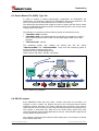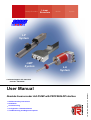
1
Rotary Encoders
Linear
Encoders
Motion
System
LP
System
LMP
System
LA
System
• Software/Support CD: 490-01001
- Soft-No.: 490-00406
• Additional safety instructions
• Installation
• Commissioning
• Configuration / Parameterization
• Troubleshooting and Diagnostic options
TR - ELA - BA - GB - 0001 - 05
Absolute linear encoder LA/LP/LMP with PROFIBUS-DP interface
08/08/2007
User Manual
TR-Electronic GmbH
D-78647 Trossingen
Eglishalde 6
Tel.: (0049) 07425/228-0
Fax: (0049) 07425/228-33
E-mail: [email protected]
http://www.tr-electronic.de
Copyright protection
This Manual, including the illustrations contained therein, is subject to copyright
protection. Use of this Manual by third parties in contravention of copyright
regulations is forbidden. Reproduction, translation as well as electronic and
photographic archiving and modification require the written content of the
manufacturer. Offenders will be liable for damages.
Subject to amendments
Any technical changes that serve the purpose of technical progress, reserved.
Document information
Release date/Rev. date:
Document rev. no.:
File name:
Author:
08/08/2007
TR - ELA - BA - GB - 0001 - 05
TR-ELA-BA-GB-0001-05.DOC
MÜJ
Font styles
Italic or bold font styles are used for the title of a document or are used for
highlighting.
Courier font displays text, which is visible on the display or screen and software
menu selections.
″<
> ″ indicates keys on your computer keyboard (such as <RETURN>).
Trademarks
SIMATIC S5, STEP-5 and COM-ET-200 are registered trademarks of SIEMENS AG.
PROFIBUS-DP and the PROFIBUS logo are registered trademarks of the Profibus
User Organisation (PNO)
© TR-Electronic GmbH 2007, All Rights Reserved
Page 2 of 50
Printed in the Federal Republic of Germany
TR - ELA - BA - GB - 0001 - 05
08/08/2007
Contents
Contents
Contents .............................................................................................................................................. 3
Revision index .................................................................................................................................... 5
1 General information ........................................................................................................................ 6
1.1 Applicability ............................................................................................................................. 6
1.2 Abbreviations used / Terminology .......................................................................................... 7
2 Additional safety instructions........................................................................................................ 8
2.1 Definition of symbols and instructions .................................................................................... 8
2.2 Additional instructions for proper use ..................................................................................... 8
2.3 Organizational measures........................................................................................................ 9
3 Technical data.................................................................................................................................. 10
3.1 Electrical characteristics ......................................................................................................... 10
4 Interface information’s.................................................................................................................... 11
4.1 PROFIBUS.............................................................................................................................. 11
4.1.1 DP Communication protocol ................................................................................... 11
5 Installation / Preparation for commissioning ............................................................................... 12
5.1 PROFIBUS – interface............................................................................................................ 12
5.1.1 RS485 Data transmission technology .................................................................... 12
5.1.2 Bus termination ....................................................................................................... 13
5.1.3 Bus address ............................................................................................................ 13
5.2 Shield cover ............................................................................................................................ 14
6 Commissioning................................................................................................................................ 16
6.1 Requirements for start-up on IM-308-C.................................................................................. 16
6.2 Requirements for start-up on SIMATIC-S7 ............................................................................ 16
6.3 Device Master File (GSD), Type file ....................................................................................... 17
6.4 PNO ID number ...................................................................................................................... 17
6.5 Starting up on the PROFIBUS ................................................................................................ 18
6.6 Bus status display................................................................................................................... 19
7 Parameterization and configuration .............................................................................................. 20
7.1 Overview ................................................................................................................................. 21
7.2 PNO CLASS 1 16 bits........................................................................................................... 22
7.3 PNO CLASS 1 32 bits........................................................................................................... 23
7.4 PNO CLASS 2 16 bits........................................................................................................... 24
7.5 PNO CLASS 2 32 bits........................................................................................................... 26
© TR-Electronic GmbH 2007, All Rights Reserved
Printed in the Federal Republic of Germany
08/08/2007
TR - ELA - BA - GB - 0001 - 05
Page 3 of 50
Contents
7.6 TR-extended 32 Bit................................................................................................................. 28
7.7 TR-extended + Speed 32 Bit .................................................................................................. 31
7.8 Preset adjustment function ..................................................................................................... 34
7.9 Description of the operating parameters ................................................................................ 35
7.9.1 Code sequence....................................................................................................... 35
7.9.2 Class 2 Functionality............................................................................................... 35
7.9.3 Diagnostic alarm ..................................................................................................... 35
7.9.4 Scaling function....................................................................................................... 35
7.9.5 Total measuring range, hi/lo ................................................................................... 36
7.9.6 Preset 1 value, hi/lo ................................................................................................ 36
7.9.7 Speed resolution, 0.1mm/s ..................................................................................... 37
7.9.8 Input of parameters with data format 32 bits .......................................................... 37
7.10 Configuration example, SIMATIC® Manager V5.3 ............................................................... 38
8 Troubleshooting and diagnosis options....................................................................................... 42
8.1 Optical displays, LEDs............................................................................................................ 42
8.2 Use of the PROFIBUS diagnosis............................................................................................ 43
8.2.1 Standard diagnosis ................................................................................................. 43
8.2.1.1 Station status 1................................................................................................................................ 44
8.2.1.2 Station status 2................................................................................................................................ 44
8.2.1.3 Station status 3................................................................................................................................ 44
8.2.1.4 Master address................................................................................................................................ 45
8.2.1.5 Manufacturer's identifier .................................................................................................................. 45
8.2.1.6 Length (in bytes) of the extended diagnosis.................................................................................... 45
8.2.2 Extended diagnosis................................................................................................. 46
8.2.2.1 Alarms ............................................................................................................................................. 46
8.2.2.2 Operating status .............................................................................................................................. 47
8.2.2.3 Encoder type ................................................................................................................................... 47
8.2.2.4 Measuring step ................................................................................................................................ 47
8.2.2.5 Number of resolvable revolutions .................................................................................................... 47
8.2.2.6 Additional alarms ............................................................................................................................. 47
8.2.2.7 Alarms supported ............................................................................................................................ 48
8.2.2.8 Warnings ......................................................................................................................................... 48
8.2.2.9 Warnings supported ........................................................................................................................ 48
8.2.2.10 Profile version................................................................................................................................ 48
8.2.2.11 Software version............................................................................................................................ 49
8.2.2.12 Operating hours counter................................................................................................................ 49
8.2.2.13 Offset value ................................................................................................................................... 49
8.2.2.14 Manufacturer's offset value............................................................................................................ 49
8.2.2.15 Number of steps per revolution ..................................................................................................... 49
8.2.2.16 Total measuring range................................................................................................................... 49
8.2.2.17 Serial number ................................................................................................................................ 49
8.2.2.18 Manufacturer's diagnoses.............................................................................................................. 50
8.3 Other faults ............................................................................................................................. 50
Appendix
Pin assignment
LA-66, 8-pol. MINI-COMBICON – Connector, Preset ......................... TR-ELA-TI-GB-0005
LA-66, 5 x 2-pol. Screw terminal, Preset ............................................. TR-ELA-TI-GB-0024
LA-66, 5 x 2-pol. Screw terminal, 3 x M12.........................................TR-ELA-TI-DGB-0047
LP-38.................................................................................................... TR-ELA-TI-GB-0025
LA-46 / LP-46, Cable screw glands ..................................................... TR-ELA-TI-GB-0044
LA-46 / LP-46, 2 x M12, 1 x M8 .........................................................TR-ELA-TI-DGB-0051
LMP-30, 3 x M12................................................................................TR-ELA-TI-DGB-0055
LMP-30, Cable screw glands.............................................................TR-ELA-TI-DGB-0060
LMP-30, 2 x M12, 1 x M8...................................................................TR-ELA-TI-DGB-0061
© TR-Electronic GmbH 2007, All Rights Reserved
Page 4 of 50
Printed in the Federal Republic of Germany
TR - ELA - BA - GB - 0001 - 05
08/08/2007
Revision index
Revision index
Revision
Date
Index
First release
07/16/97
00
Operating manual added with LP-38.
Pin assignment appended separately.
12/09/98
01
Expansion of the parameterization function with the parameter "Diagnostic
01/18/01
alarm"
02
Modification of the device- and type-file designations, which were already
06/11/02
created quite a long time ago (05/06/99).
03
New GSD-file "TR03AAAC.GSD" / 02/17/05, useable for linear-encoder with
03/01/05
speed-output
04
General technical modifications, layout modifications
05
© TR-Electronic GmbH 2007, All Rights Reserved
Printed in the Federal Republic of Germany
08/08/2007
08/08/07
TR - ELA - BA - GB - 0001 - 05
Page 5 of 50
General information
1 General information
This interface-specific User Manual includes the following topics:
•
Safety instructions in additional to the basic safety instructions defined in the
Assembly Instructions
•
Electrical characteristics
•
Installation
•
Commissioning
•
Configuration / parameterization
•
Troubleshooting and diagnostic options
As the documentation is arranged in a modular structure, this User Manual is
supplementary to other documentation, such as product datasheets, dimensional
drawings, leaflets and the assembly instructions etc.
The User Manual may be included in the customer's specific delivery package or it
may be requested separately.
1.1 Applicability
This User Manual applies exclusively to the following measuring system models with
PROFIBUS-DP interface:
•
•
•
LA
LP
LMP
The products are labelled with affixed nameplates and are components of a system.
The following documentation therefore also applies:
•
•
•
the operator's operating instructions specific to the system,
this User Manual,
and the assembly instructions TR-ELA-BA-DGB-0004, which is enclosed
when the device is delivered
© TR-Electronic GmbH 2007, All Rights Reserved
Page 6 of 50
Printed in the Federal Republic of Germany
TR - ELA - BA - GB - 0001 - 05
08/08/2007
General information
1.2 Abbreviations used / Terminology
LA
Linear-Absolute Measuring System, type with tube-housing
LP
Linear-Absolute Measuring System, type with profile-housing
LMP
Linear-Absolute Measuring System, type with profile-housing
DDLM
Direct Data Link Mapper, interface between PROFIBUS-DP
functions and measuring system software
DP
Decentralized Periphery
EMC
Electro Magnetic Compatibility
GSD
Device Master File
PNO
PROFIBUS User Organization (PROFIBUS Nutzerorganisation)
PROFIBUS
Manufacturer independent, open field bus standard
© TR-Electronic GmbH 2007, All Rights Reserved
Printed in the Federal Republic of Germany
08/08/2007
TR - ELA - BA - GB - 0001 - 05
Page 7 of 50
Additional safety instructions
2 Additional safety instructions
2.1 Definition of symbols and instructions
means that death, serious injury or major damage to property
could occur if the stated precautions are not met.
WARNING!
means that minor injuries or damage to property can occur if the
stated precautions are not met.
CAUTION !
indicates important information’s or features and application tips
for the product used.
2.2 Additional instructions for proper use
The measuring system is designed for operation with PROFIBUS-DP networks
according to the European standards EN 50170 and EN 50254 up to max. 12 Mbaud.
The parameterization and the device diagnosis are performed through the PROFIBUS
master according to the profile for encoders version 1.1 of the PROFIBUS User
Organization (PNO).
The technical guidelines for the structure of the PROFIBUS-DP network from the
PROFIBUS User Organization are always to be observed in order to ensure safe
operation.
Proper use also includes:
•
observing all instructions in this User Manual,
•
observing the assembly instructions. The "Basic safety instructions" in
particular must be read and understood prior to commencing work.
© TR-Electronic GmbH 2007, All Rights Reserved
Page 8 of 50
Printed in the Federal Republic of Germany
TR - ELA - BA - GB - 0001 - 05
08/08/2007
Additional safety instructions
2.3 Organizational measures
•
This User Manual must always kept accessible at the site of operation of the
measuring system.
•
Prior to commencing work, personnel working with the measuring system
must have read and understood
-
the assembly instructions, in particular the chapter "Basic safety
instructions",
-
and this User Manual, in particular the chapter "Additional safety
instructions".
This particularly applies for personnel who are only deployed occasionally,
e.g. at the parameterization of the measuring system.
© TR-Electronic GmbH 2007, All Rights Reserved
Printed in the Federal Republic of Germany
08/08/2007
TR - ELA - BA - GB - 0001 - 05
Page 9 of 50
Technical data
3 Technical data
3.1 Electrical characteristics
Supply voltage ....................................... 19…27 V DC, twisted in pairs and shielded
Current consumption without load ..... < 450 mA
Measuring principle............................... magnetostrictive
* Resolution............................................ 0.01 mm / 0.005 mm, see nameplate
Output capacity ..................................... ≤ 24 bit
Output code ........................................... Binary
Standard baud rates.............................. 9.6 kBaud to 12 MBaud
Cycle time internally, LA-46/LP-46
≤ 1.0 m...................................
≤ 1.5 m...................................
≤ 2.0 m...................................
≤ 2.5 m...................................
> 2.5 m...................................
1.0 ms
1.5 ms
2.0 ms
2.5 ms
3.0 ms
Cycle time internally, LMP-30
≤ 1.0 m...................................
≤ 2.0 m...................................
≤ 3.0 m...................................
> 3.0 m ...................................
1.0 ms
1.5 ms
2.0 ms
3.5 ms
Station addresses.................................. 3 - 99, set on BCD rotary switch
PROFIBUS-DP standard ....................... EN 50170 and EN 50254
Transmission ......................................... RS485, twisted and shielded copper cable with a single
conductor pair (cable type A)
Special features ..................................... Programming takes place via the parameterization
telegram when the measuring system or the PROFIBUSDP master starts up.
- Measuring length in steps
- Code sequence
- Adjustment in cycle
- Preset value for ext. Preset input
- Resolution for speed output
EMC......................................................... DIN EN 61000-6-2 / DIN EN 61000-4-2 / DIN EN 61000-4-4
* parameterizable via PROFIBUS-DP
© TR-Electronic GmbH 2007, All Rights Reserved
Page 10 of 50
Printed in the Federal Republic of Germany
TR - ELA - BA - GB - 0001 - 05
08/08/2007
Interface information’s
4 Interface information’s
4.1 PROFIBUS
PROFIBUS is a continuous, open, digital communication system with a broad range of
applications, particularly in manufacturing and process automation. PROFIBUS is
suitable for fast, time-sensitive and complex communication tasks.
PROFIBUS communication is based on the international standards IEC 61158 and
IEC 61784. The application and engineering aspects are defined in the PROFIBUS
User Organization guidelines. These serve to fulfil the user requirements for a
manufacturer independent and open system where the communication between
devices from different manufacturers is guaranteed without modification of the
devices.
The PROFIBUS User Organization has implemented a special profile for encoders.
The profile describes the connection of rotary, angular and linear encoders with single
turn or multi turn resolution to the DP. Two device classes define the basic and
additional functions, e.g. scaling, alarm management and diagnosis.
The measuring systems support Device Classes 1 and 2 as defined in the profile, as
well as additional TR-specific functions.
A description of the encoder profile (order no.: 3.062) and further information on
PROFIBUS is available from the PROFIBUS User Organization:
PROFIBUS Nutzerorganisation e.V.,
Haid-und-Neu-Str. 7
D-76131 Karlsruhe,
http://www.profibus.com/
Tel.: ++ 49 (0) 721 / 96 58 590
Fax: ++ 49 (0) 721 / 96 58 589
e-mail: mailto:[email protected]
4.1.1 DP Communication protocol
The measuring systems support the DP communication protocol, which is designed
for fast data exchange on the field level. The basic functionality is defined by the
performance level V0. This includes cyclic data exchange, as well as the station,
module and channel-specific diagnosis.
© TR-Electronic GmbH 2007, All Rights Reserved
Printed in the Federal Republic of Germany
08/08/2007
TR - ELA - BA - GB - 0001 - 05
Page 11 of 50
Installation / Preparation for commissioning
5 Installation / Preparation for commissioning
5.1 PROFIBUS – interface
5.1.1 RS485 Data transmission technology
All devices are connected in a bus structure (line). Up to 32 subscribers (master or
slaves) can be connected together in a segment.
The bus is terminated with an active bus termination at the beginning and end of each
segment. For stable operation, it must be ensured that both bus terminations are
always supplied with voltage. The bus termination can be switched in the measuring
system connector hood.
Repeaters (signal amplifiers) have to be used with more than 32 subscribers or to
expand the network scope in order to connect the various bus segments.
All cables used must conform with the PROFIBUS specification for the following
copper data wire parameters:
Parameter
Cable type A
Wave impedance in Ω
Operating capacitance (pF/m)
Loop resistance (Ω/km)
Wire diameter (mm)
Wire cross-section (mm²)
135...165 at a frequency of 3...20 MHz
30
≤ 110
> 0.64
> 0.34
The PROFIBUS transmission speed may be set between 9.6 kBit/s and 12 Mbit/s and
is automatically recognized by the measuring system. It is selected for all devices on
the bus at the time of commissioning the system.
The range is dependent on the transmission speed for cable type A:
Baud rate (kbits/s)
Range / Segment
9.6
19.2
93.75
187.5
500
1500
12000
1200 m
1200 m
1200 m
1000 m
400 m
200 m
100 m
A shielded data cable must be used to achieve high electromagnetic interference
stability. The shielding should be connected with low resistance to protective ground
using large shield clips at both ends. It is also important that the data line is routed
separate from power current carrying cables if at all possible. At data speed ≥ 1.5
Mbit, drop lines should be avoided under all circumstances.
The measuring system connector hood offers the possibility of connecting the inward
and outward data cables directly to the removable connector hood. This avoids drop
lines and the bus connector can be connected to and disconnected from the bus at
any time without interruption of data traffic.
The PROFIBUS guidelines and other applicable standards and guidelines are to be
observed to insure safe and stable operation!
In particular, the applicable EMC directive and the shielding and grounding guidelines
must be observed!
© TR-Electronic GmbH 2007, All Rights Reserved
Page 12 of 50
Printed in the Federal Republic of Germany
TR - ELA - BA - GB - 0001 - 05
08/08/2007
Installation / Preparation for commissioning
5.1.2 Bus termination
ON
If the measuring system is the last slave
in the PROFIBUS segment, the bus is
to be terminated with the termination
switch = ON. In this state, the
subsequent PROFIBUS is decoupled.
OFF
5.1.3 Bus address
Valid PROFIBUS addresses: 3 - 99
78
78
01
0
10
456
© TR-Electronic GmbH 2007, All Rights Reserved
Printed in the Federal Republic of Germany
08/08/2007
1
10
9
456
The device does not start up with an
invalid station address, LEDs = OFF.
01
23
1
10 : Setting the 10th position
9
23
0
10 : Setting the 1st position
TR - ELA - BA - GB - 0001 - 05
Page 13 of 50
Installation / Preparation for commissioning
5.2 Shield cover
The shield cover is connected with a special EMC cable gland, whereby the cable
shielding is fitted on the inside.
Cable gland assembly, variant A
Pos. 1 Nut
Pos. 2 Seal
Pos. 3 Contact bush
Pos. 5 Screw socket
1. Cut shield braid / shield foil back to dimension "X".
2. Slide the nut (1) and seal / contact bush (2) + (3) over the cable.
3. Bend the shield braining / shield foil to 90° (4).
4. Slide seal / contact bush (2) + (3) up to the shield braining / shield foil.
5. Assemble screw socket (5) on the housing.
6. Push seal / contact bush (2) + (3) flush into the screw socket (5).
7. Screw the nut (1) to the screw socket (5).
© TR-Electronic GmbH 2007, All Rights Reserved
Page 14 of 50
Printed in the Federal Republic of Germany
TR - ELA - BA - GB - 0001 - 05
08/08/2007
Installation / Preparation for commissioning
Cable gland assembly, variant B
Pos. 1
Pos. 2
Pos. 3
Pos. 4
Nut
Clamping ring
Inner O-ring
Screw socket
1. Cut shield braid / shield foil back to dimension "X" + 2mm.
2. Slide the nut (1) and clamping ring (2) over the cable.
3. Bend the shield braining / shield foil to approx. 90°.
4. Push clamping ring (2) up to the shield braid / shield foil and wrap the braiding
back around the clamping ring (2), such that the braiding goes around the
inner O-ring (3), and is not above the cylindrical part or the torque supports.
5. Assemble screw socket (4) on the housing.
6. Insert the clamping ring (2) in the screw socket (4) such that the torque
supports fit in the slots in the screw socket (4).
7. Screw the nut (1) to the screw socket (4).
1
2
3
4
© TR-Electronic GmbH 2007, All Rights Reserved
Printed in the Federal Republic of Germany
08/08/2007
TR - ELA - BA - GB - 0001 - 05
Page 15 of 50
Commissioning
6 Commissioning
6.1 Requirements for start-up on IM-308-C
In order to start up the measuring system on an IM-308-C, the following minimum
requirements must be met :
• COM-ET-200 for Windows Version 2.0 or higher.
• IM-308-C Edition 3 or higher.
• Device master file, Type file for COM-ET-200 for Windows:
Software/Support CD: Order-No.: 490-01001, Soft-No.: 490-00406.
6.2 Requirements for start-up on SIMATIC-S7
In order to start up the measuring system on a programmable controller of the
SIMATIC S7 type, the following minimum requirements must be met:
• STEP-7 for Windows Version 2.1 Edition 4 or higher. The Version 2.1 basic
package supplied by Siemens does not support the parameterization function via
input masks !
• SIMATIC S7-300 or S7-400 with PROFIBUS-DP interface.
• Device master file, Type file for COM-ET-200 for Windows:
Software/Support CD: Order-No.: 490-01001, Soft-No.: 490-00406.
© TR-Electronic GmbH 2007, All Rights Reserved
Page 16 of 50
Printed in the Federal Republic of Germany
TR - ELA - BA - GB - 0001 - 05
08/08/2007
Commissioning
6.3 Device Master File (GSD), Type file
In order to achieve a simple plug-and-play configuration for PROFIBUS, the
characteristic communication features for PROFIBUS devices were defined in the
form of an electronic device datasheet (device master file, GSD file).
The defined file format allows the projection system to easily read the device master
data of the PROFIBUS measuring system and automatically take it into account when
configuring the bus system.
The GSD file is a component of the measuring system and has the file name:
● "TR02AAAC.GSD", standard
● "TR03AAAC.GSD", with speed output for LA-46 and LP-46 systems. In case of
other measuring systems the module “TR-extended+Speed 32Bit” must not be
projected.
● "TRAAAC2X.200", type file
The measuring system also includes two bitmap files with the names
"TRAAAC2N.BMP" and "TRAAAC2S.BMP", which show the measuring system in
normal operation as well as with a fault.
The files are on the Software/Support CD:
Order number: 490-01001, Soft-No.: 490-00406.
tem
Sys
C
gu
onf i
ratio
n
PROFIBUS
Configurator
PLC
Electronic Device Data Sheets (GSD Files)
PROFIBUS
Figure 1: GSD for the configuration
6.4 PNO ID number
Every PROFIBUS slave and every Class 1 master must have an ID number. It is
required so that a master can identify the type of the connected device without
significant protocol overhead. The master compares the ID numbers of the devices
connected with the ID numbers of the projection data specified in the projection tool.
The transfer of utility data only starts once the correct device types have been
connected with the correct station addresses on the bus. This achieves a high level of
security against projection errors.
The measuring system has the PNO ID number AAAC (hex). This number is reserved
and is stored at the PNO.
© TR-Electronic GmbH 2007, All Rights Reserved
Printed in the Federal Republic of Germany
08/08/2007
TR - ELA - BA - GB - 0001 - 05
Page 17 of 50
Commissioning
6.5 Starting up on the PROFIBUS
Before the measuring system can be accepted for "Data_Exchange", the master must
firstly initialize the measuring system at start-up. The resulting data exchange
between the master and the measuring system (slave) is divided into the
parameterization, configuration and data transfer phases.
It is checked whether the projected nominal configuration agrees with the actual
device configuration. The device type, the format and length information as well as the
number of inputs and outputs must agree in this check. The user is therefore reliably
protected against parameterization errors.
If the check was successful, it is switched over into the DDLM_Data_Exchange mode.
In this mode, the measuring system e.g. sends its actual position, and the preset
adjustment function can be performed.
DP Watchdog
Power On/
Reset
Initialization
WPRM
Configuration not ok
Parameter not ok
Parameter ok
WCFG
Unlock
Configuration not ok
Parameter not ok
Output length false
Configuration ok
DXCHG
WPRM = Wait Parameter
WCFG = Wait Configuration
DXCHG = Data Exchange
Parameter and Configuration ok
Outputs Receiver/
Return Inputs
Figure 2: DP slave initialization
© TR-Electronic GmbH 2007, All Rights Reserved
Page 18 of 50
Printed in the Federal Republic of Germany
TR - ELA - BA - GB - 0001 - 05
08/08/2007
Commissioning
6.6 Bus status display
The measuring system has two LEDs in the connection hood. A red LED (Bus Fail) to
display faults and a green LED (Bus Run) to display status information.
When the measuring system starts up, both LEDs flash briefly. The display then
depends on the operational state.
= ON
= OFF
= 1 Hz
= 10 Hz
LED, green
Bus Run
Ready for operation
Supply absent, hardware error
Parameterization or configuration error
LED, red
Bus Fail
No error, bus in cycle
Measuring system is not addressed by the master, no data exchange
Measuring system in Data Exchange, but no magnet was detected.
Corresponding measures in case of an error see chapter “Troubleshooting and
diagnosis options”, page 42.
© TR-Electronic GmbH 2007, All Rights Reserved
Printed in the Federal Republic of Germany
08/08/2007
TR - ELA - BA - GB - 0001 - 05
Page 19 of 50
Parameterization and configuration
7 Parameterization and configuration
Parameterization
Parameterization means providing a PROFIBUS-DP slave with certain information required for
operation prior to commencing the cyclic exchange of process data. The measuring system
requires e.g. data for Resolution, Count direction etc.
Normally the configuration program provides an input mask for the PROFIBUS-DP master with
which the user can enter parameter data or select from a list. The structure of the input mask is
stored in the device master file. The number and type of the parameter to be entered by the user
depends on the choice of nominal configuration.
The configuration described as follows contains configuration and parameter data
coded in their bit and byte positions. This information is e.g. only of significance in
troubleshooting or with bus master systems for which this information has to be
entered manually.
Modern configuration tools provide an equivalent graphic interface for this purpose.
Here the bit and byte positions are automatically managed in the "background". The
configuration example on page 38 illustrates this again.
Configuration
The definition of the I/O length, I/O data type etc. takes place automatically for most bus
masters. This information only has to be entered manually for a few bus masters.
Configuration means that the length and type of process data must be specified and how it is to
be treated. The configuration program normally provides an input list for this purpose, in which
the user has to enter the corresponding identifiers.
As the measuring system supports several possible configurations, the identifier to be entered is
preset dependent on the required nominal configuration, so that only the I/O addresses need to
be entered. The identifiers are stored in the device master file.
The measuring system uses a different number of input and output words on the PROFIBUS
dependent on the required nominal configuration.
Structure of the configuration byte (compact format):
7
2
6
2
5
2
4
2
3
2
2
2
1
2
0
2
Length of the I/O data:
0-15 for 1 to 16 bytes or words
Type of I/O data:
00 = empty,
10 = output,
01 = input,
11 = input/output
Format:
0 = BYTE,
1 = WORD
Consistency:
0 = Consistency about one byte or word
1 = Consistency about the complete module
© TR-Electronic GmbH 2007, All Rights Reserved
Page 20 of 50
Printed in the Federal Republic of Germany
TR - ELA - BA - GB - 0001 - 05
08/08/2007
Parameterization and configuration
7.1 Overview
Configuration Operating parameters
*·Length Features
PNO Class 1
Page 22
- Code sequence
16 bit IN
PNO Class 1
Page 23
- Code sequence
32 bit IN
-
No measuring system scaling, the measuring
system has the base resolution according to the
nameplate
-
16 byte diagnosis data
-
Code sequence
- Code sequence
PNO Class 2
Page 24
- Class 2 functionality
- Scaling function
16 bit IN
16 bit OUT
- Total measuring range
- Code sequence
PNO Class 2
Page 26
- Class 2 functionality
- Scaling function
-
Measuring system scaling is possible
-
Preset adjustment via the bus
-
Code sequence
32 bit IN
32 bit OUT
- Total measuring range
- Code sequence
TR-extended
32 Bit
Page 28
- Class 2 functionality
- Scaling function
32 bit IN
32 bit OUT
- Diagnostic alarm
-
Measuring system scaling possible
-
Preset adjustment via the bus
-
Code sequence
-
Preselection of the values for the external Preset
inputs, depends on the type of measuring
system
- Total measuring range
- Preset value
- Code sequence
TRextended+Speed
32 Bit
Page 31
- Class 2 functionality
- Scaling function
- Diagnostic alarm
- Total measuring range
- Preset value
- Speed resolution
32 bit IN
16 bit IN
32 bit OUT
-
Measuring system scaling possible
-
Preset adjustment via the bus
-
Code sequence
-
Preselection of the values for the external Preset
inputs, depends on the type of measuring
system
-
Speed output
* from the bus master perspective
© TR-Electronic GmbH 2007, All Rights Reserved
Printed in the Federal Republic of Germany
08/08/2007
TR - ELA - BA - GB - 0001 - 05
Page 21 of 50
Parameterization and configuration
7.2 PNO CLASS 1 16 bits
Data exchange
DDLM_Data_Exchange
Input word IWx
Byte
1
Bit
Data
2
15 – 8
7–0
15
8
2 –2
27 – 2 0
Data_Exchange – Position data
see note on page 20
Configuration data
Device Class 1: 0xD0 (1 word input data for position value, consistent)
DDLM_Chk_Cfg
Byte
1
Bit
Data
7
1
Consistency
6
1
D
Word format
5–4
01
Input data
3–0
0
0
Length code
see note on page 20
Overview of operating parameters
DDLM_Set_Prm
Byte
9
Bit
Data
7–0
27 – 2 0
Bit
0
Definition
= 0 (DEFAULT)
=1
Code sequence
increasing position
values to the rod end
decreasing position
values to the rod end
© TR-Electronic GmbH 2007, All Rights Reserved
Page 22 of 50
Page
35
Printed in the Federal Republic of Germany
TR - ELA - BA - GB - 0001 - 05
08/08/2007
Parameterization and configuration
7.3 PNO CLASS 1 32 bits
Data exchange
DDLM_Data_Exchange
Input double word IDx
Byte
1
2
Bit
Data
31 – 24
231 – 224
3
4
23 – 16
15 – 8
223 – 216
215 – 28
Data_Exchange – Position data
7–0
27 – 2 0
see note on page 20
Configuration data
Device Class 1: 0xD1 (1 double word input data for position value, consistent)
DDLM_Chk_Cfg
Byte
1
Bit
Data
7
1
Consistency
6
1
D
Word format
5–4
01
Input data
3–0
1
1
Length code
see note on page 20
Overview of operating parameters
DDLM_Set_Prm
Byte
9
Bit
Data
7–0
27 – 2 0
Bit
0
Definition
= 0 (DEFAULT)
=1
Code sequence
increasing position
values to the rod end
decreasing position
values to the rod end
35
© TR-Electronic GmbH 2007, All Rights Reserved
Printed in the Federal Republic of Germany
08/08/2007
Page
TR - ELA - BA - GB - 0001 - 05
Page 23 of 50
Parameterization and configuration
7.4 PNO CLASS 2 16 bits
Data exchange
DDLM_Data_Exchange
Input word IWx
Byte
1
Bit
Data
2
15 – 8
7–0
215 – 28
27 – 2 0
Data_Exchange – Position data
Format for preset adjustment value (description of the function see page 34)
Output word OWx
Byte
Bit
Data
1
15
0/1
Preset execution
2
14 – 8
7–0
214 – 28
27 – 2 0
Preset adjustment value
see note on page 20
Configuration data
Device Class 2: 0xF0
(1 word input data for position value, consistent /
1 word output data for preset adjustment, consistent)
DDLM_Chk_Cfg
Byte
Bit
Data
1
7
1
Consistency
6
1
F
Word format
© TR-Electronic GmbH 2007, All Rights Reserved
Page 24 of 50
5–4
11
Input data
3–0
0
0
Length code
Printed in the Federal Republic of Germany
TR - ELA - BA - GB - 0001 - 05
08/08/2007
Parameterization and configuration
see note on page 20
Overview of operating parameters
Bit coded operating parameters
DDLM_Set_Prm
Byte
9
Bit
Data
7–0
27 – 2 0
x = default setting
Bit Definition
=0
0
Code sequence
1
Class 2 Functionality
2
unused
3
Scaling function
=1
Page
increasing position values
to the rod end
X
decreasing position
values to the rod end
35
no
X
yes
35
-
-
switched off
X
switched on
35
Associated operating parameters for scaling
Description see page 35, 36
DDLM_Set_Prm
unsigned32
Byte
Bit
Data
Default (dec.)
10
11
12
13
31 – 24
231 – 224
23 – 16
223 – 216
15 – 8
215 – 28
7–0
27 – 2 0
0
Steps per revolution, unused
DDLM_Set_Prm
unsigned32
Byte
14
15
16
17
Bit
Data
31 – 24
231 – 224
23 – 16
223 – 216
15 – 8
215 – 28
7–0
27 – 2 0
hi
0x00
Default (dec.)
lo
0x01
0x86
100 000
Total measuring range, hi/lo
© TR-Electronic GmbH 2007, All Rights Reserved
Printed in the Federal Republic of Germany
08/08/2007
0xA0
TR - ELA - BA - GB - 0001 - 05
Page 25 of 50
Parameterization and configuration
7.5 PNO CLASS 2 32 bits
Data exchange
DDLM_Data_Exchange
Input double word IDx
Byte
1
2
Bit
Data
31 – 24
231 – 224
3
4
23 – 16
15 – 8
223 – 216
215 – 28
Data_Exchange – Position data
7–0
27 – 2 0
Format for preset adjustment value (description of the function see page 34)
Output double word ODx
Byte
Bit
Data
1
31
0/1
Preset
execution
30 – 24
230 – 224
2
3
4
23 – 16
223 – 216
15 – 8
215 – 28
7–0
27 – 2 0
Preset adjustment value
see note on page 20
Configuration data
Device Class 2: 0xF1
(1 double word input data for position value, consistent /
1 double word output data for preset adjustment, consistent)
DDLM_Chk_Cfg
Byte
Bit
Data
1
7
1
Consistency
6
1
F
Word format
© TR-Electronic GmbH 2007, All Rights Reserved
Page 26 of 50
5–4
11
Input data
3–0
1
1
Length code
Printed in the Federal Republic of Germany
TR - ELA - BA - GB - 0001 - 05
08/08/2007
Parameterization and configuration
see note on page 20
Overview of operating parameters
Bit coded operating parameters
DDLM_Set_Prm
Byte
9
Bit
Data
7–0
27 – 2 0
x = default setting
Bit Definition
=0
0
Code sequence
1
Class 2 Functionality
2
unused
3
Scaling function
=1
Page
increasing position values
to the rod end
X
decreasing position
values to the rod end
35
no
X
yes
35
-
-
switched off
X
switched on
35
Associated operating parameters for scaling
Description see page 35, 36
DDLM_Set_Prm
unsigned32
Byte
Bit
Data
Default (dec.)
10
11
12
13
31 – 24
231 – 224
23 – 16
223 – 216
15 – 8
215 – 28
7–0
27 – 2 0
0
Steps per revolution, unused
DDLM_Set_Prm
unsigned32
Byte
14
15
16
17
Bit
Data
31 – 24
231 – 224
23 – 16
223 – 216
15 – 8
215 – 28
7–0
27 – 2 0
hi
0x00
Default (dec.)
lo
0x01
0x86
100 000
Total measuring range, hi/lo
© TR-Electronic GmbH 2007, All Rights Reserved
Printed in the Federal Republic of Germany
08/08/2007
0xA0
TR - ELA - BA - GB - 0001 - 05
Page 27 of 50
Parameterization and configuration
7.6 TR-extended 32 Bit
Data exchange
DDLM_Data_Exchange
Input double word IDx
Byte
1
2
Bit
Data
31 – 24
231 – 224
3
4
23 – 16
15 – 8
223 – 216
215 – 28
Data_Exchange – Position data
7–0
27 – 2 0
Format for preset adjustment value (description of the function see page 34)
Output double word ODx
Byte
Bit
Data
1
31
0/1
Preset
execution
30 – 24
230 – 224
2
3
4
23 – 16
223 – 216
15 – 8
215 – 28
7–0
27 – 2 0
Preset adjustment value
see note on page 20
Configuration data
TR-extended: 0xF1
(1 double word input data for position value, consistent /
1 double word output data for preset adjustment, consistent)
DDLM_Chk_Cfg
Byte
Bit
Data
1
7
1
Consistency
6
1
F
Word format
© TR-Electronic GmbH 2007, All Rights Reserved
Page 28 of 50
5–4
11
Input data
3–0
1
1
Length code
Printed in the Federal Republic of Germany
TR - ELA - BA - GB - 0001 - 05
08/08/2007
Parameterization and configuration
see note on page 20
Overview of operating parameters
Parameter
Data type
Byte
Format
Description
page 35
Code sequence
bit
9
page 29
Class 2 functionality
bit
9
page 29
page 35
Scaling function
bit
9
page 29
page 35
Diagnostic alarm
bit
9
page 29
page 35
Total measuring range, hi/lo
unsigned32
14 – 17
page 30
page 36
Preset 1 value, hi/lo
unsigned32
18 – 21
page 30
page 36
Bit coded operating parameters
DDLM_Set_Prm
Byte
Bit
9
7–0
27 – 2 0
Data
x = default setting
Bit Definition
=0
=1
increasing position values
to the rod end
X
decreasing position
values to the rod end
35
no
X
yes
35
Diagnostic alarm
switched off
X
switched on
35
Scaling function
switched off
X
switched on
35
0
Code sequence
1
Class 2 functionality
2
3
© TR-Electronic GmbH 2007, All Rights Reserved
Printed in the Federal Republic of Germany
08/08/2007
Page
TR - ELA - BA - GB - 0001 - 05
Page 29 of 50
Parameterization and configuration
Associated operating parameters for scaling
Description see page 35, 36
DDLM_Set_Prm
unsigned32
Byte
Bit
Data
Default (dec.)
10
11
12
13
31 – 24
231 – 224
23 – 16
223 – 216
15 – 8
215 – 28
7–0
27 – 2 0
0
Steps per revolution, unused
DDLM_Set_Prm
unsigned32
Byte
14
15
16
17
Bit
Data
31 – 24
231 – 224
23 – 16
223 – 216
15 – 8
215 – 28
7–0
27 – 2 0
hi
0x00
lo
0x01
0x86
100 000
Total measuring range, hi/lo
Default (dec.)
0xA0
Operating parameter Preset 1 value, hi/lo
Description see page 36
DDLM_Set_Prm
unsigned32
Byte
18
19
20
21
Bit
Data
31 – 24
231 – 224
23 – 16
223 – 216
15 – 8
215 – 28
7–0
27 – 2 0
hi
0x00
Default (dec.)
lo
0x00
0x00
1
Preset 1 value, hi/lo
© TR-Electronic GmbH 2007, All Rights Reserved
Page 30 of 50
0x01
Printed in the Federal Republic of Germany
TR - ELA - BA - GB - 0001 - 05
08/08/2007
Parameterization and configuration
7.7 TR-extended + Speed 32 Bit
Starting from GSD file "TR03AAAC.GSD" / 02/17/2005
Data exchange
DDLM_Data_Exchange
Input double word IDx
Byte
Bit
Data
1
31 – 24
231 – 224
2
3
23 – 16
15 – 8
223 – 216
215 – 28
Data_Exchange – Position data
4
7–0
27 – 2 0
Input word IWx
Byte
Bit
Data
1
2
15 – 8
7–0
215 – 28
27 – 2 0
Data_Exchange – Speed output
Format for preset adjustment value (description of the function see page 34)
Output double word ODx
Byte
Bit
Data
1
31
0/1
Preset
execution
30 – 24
230 – 224
2
23 – 16
223 – 216
4
7–0
27 – 2 0
Preset adjustment value
see note on page 20
Configuration data
TR-extended+Speed:
3
15 – 8
215 – 28
0xF1
(1 double word input data for position value, consistent /
1 double word output data for preset adjustment, consistent)
0xD0
(1 word input data for speed output, consistent)
DDLM_Chk_Cfg
Byte
Bit
Data
1
7
1
Consistency
6
1
F
Word format
5–4
11
Input data
3–0
1
1
Length code
DDLM_Chk_Cfg
Byte
Bit
Data
1
7
1
Consistency
6
1
D
Word format
Input data
3–0
0
0
Length code
© TR-Electronic GmbH 2007, All Rights Reserved
Printed in the Federal Republic of Germany
08/08/2007
5–4
01
TR - ELA - BA - GB - 0001 - 05
Page 31 of 50
Parameterization and configuration
see note on page 20
Overview of operating parameters
Parameter
Data type
Byte
Format
Description
Code sequence
bit
9
page 32
page 35
Class 2 functionality
bit
9
page 32
page 35
Scaling function
bit
9
page 32
page 35
Diagnostic alarm
bit
9
page 32
page 35
Total measuring range, hi/lo
unsigned32
14 – 17
page 33
page 36
Preset 1 value, hi/lo
unsigned32
18 – 21
page 33
page 36
Speed resolution
unsigned8
22
page 33
page 37
Bit coded operating parameters
DDLM_Set_Prm
Byte
Bit
9
7–0
27 – 2 0
Data
x = default setting
Bit Definition
=0
=1
increasing position values
to the rod end
X
decreasing position
values to the rod end
35
no
X
yes
35
Diagnostic alarm
switched off
X
switched on
35
Scaling function
switched off
X
switched on
35
0
Code sequence
1
Class 2 functionality
2
3
© TR-Electronic GmbH 2007, All Rights Reserved
Page 32 of 50
Page
Printed in the Federal Republic of Germany
TR - ELA - BA - GB - 0001 - 05
08/08/2007
Parameterization and configuration
Associated operating parameters for scaling
Description see page 35, 36
DDLM_Set_Prm
unsigned32
Byte
Bit
Data
Default (dec.)
10
11
12
13
31 – 24
231 – 224
23 – 16
223 – 216
15 – 8
215 – 28
7–0
27 – 2 0
0
Steps per revolution, unused
DDLM_Set_Prm
unsigned32
Byte
14
15
16
17
Bit
Data
31 – 24
231 – 224
23 – 16
223 – 216
15 – 8
215 – 28
7–0
27 – 2 0
0x01
0x86
hi
lo
0x00
Default (dec.)
0xA0
100 000
Total measuring range, hi/lo
Operating parameter Preset 1 value, hi/lo
Description see page 36
DDLM_Set_Prm
unsigned32
Byte
18
19
20
21
Bit
Data
31 – 24
231 – 224
23 – 16
223 – 216
15 – 8
215 – 28
7–0
27 – 2 0
hi
0x00
Default (dec.)
lo
0x00
0x00
1
Preset 1 value, hi/lo
0x01
Operating parameter Speed resolution
Description see page 37
DDLM_Set_Prm
unsigned8
Byte
Bit
Data
Default (dec.)
22
7–0
27 – 2 0
1
© TR-Electronic GmbH 2007, All Rights Reserved
Printed in the Federal Republic of Germany
08/08/2007
TR - ELA - BA - GB - 0001 - 05
Page 33 of 50
Parameterization and configuration
7.8 Preset adjustment function
Risk of injury and damage to property by an actual value jump when the Preset
adjustment function is performed!
WARNING !
• The preset adjustment function should only be performed when the measuring
system is at rest, otherwise the resulting actual value jump must be permitted in
the program and application!
Availability
PNO CLASS1 16 + 32
not supported!
PNO CLASS2 16 + 32
X
page 24 + 26
TR-extended
page 28
X
TR-extended+Speed
X
page 31
In order that the preset adjustment function can be used in PNO CLASS 2
configurations, the operating parameter "Scaling function" must be switched on!
The measuring system can be adjusted to an arbitrary position value in the range 0 to
measurement length in steps via the PROFIBUS.
This is achieved by setting the highest value output data bit
(231 for PNO CLASS 2-32 bit configurations and TR-extended,
or 215 for the PNO CLASS 2-16 bit configuration).
The preset adjustment value sent in the data bytes with the rising flank of the bit
"preset execution" is adopted as the position value.
There is no acknowledgement of the process via the inputs in CLASS 2 mode.
lower limit
0
upper limit
CLASS 2 16 Bit
programmed total measuring length in increments,
within ≤ 32 768
upper limit
CLASS 2 32 Bit / TR-extended
programmed total measuring length in increments,
within ≤ 16 777 216
© TR-Electronic GmbH 2007, All Rights Reserved
Page 34 of 50
Printed in the Federal Republic of Germany
TR - ELA - BA - GB - 0001 - 05
08/08/2007
Parameterization and configuration
7.9 Description of the operating parameters
7.9.1 Code sequence
Availability
PNO CLASS1 16 + 32
page 22 + 23
X
PNO CLASS2 16 + 32
X
TR-extended
page 24 + 26
X
page 28
TR-extended+Speed
X
page 31
The code sequence defines whether increasing or decreasing position values are
output from the measuring system if the magnet is slided towards the end of the rod.
7.9.2 Class 2 Functionality
Availability
PNO CLASS1 16 + 32
not supported!
PNO CLASS2 16 + 32
X
TR-extended
page 24 + 26
X
page 28
TR-extended+Speed
X
page 31
Defines the functional scope of the measuring system. Class 2 switched off means
only Class 1 functions are active in the measuring system; it does not scale the
position value and is not adjustable. The diagnosis data are limited to 16 byte.
7.9.3 Diagnostic alarm
Availability
PNO CLASS1 16 + 32
PNO CLASS2 16 + 32
TR-extended
not supported!
not supported!
page 28
X
TR-extended+Speed
X
page 31
Defines whether the measuring system triggers a "diagnosis alarm" (OB82 for
SIMATIC® S7) for an internal error (no magnet detected), also see Chapter "Alarms",
page 46.
7.9.4 Scaling function
Availability
PNO CLASS1 16 + 32
not supported!
PNO CLASS2 16 + 32
X
page 24 + 26
TR-extended
page 28
X
TR-extended+Speed
X
page 31
Defines whether the position is scaled according to the parameter "Total measuring
range".
If Class 2 is switched off, the position value cannot be scaled or adjusted.
If the scaling parameters are activated with the Scaling function, the physical
resolution of the measuring system can be changed. The position value output is
binary decoded and is calculated with a zero point correction and the code sequence
set.
© TR-Electronic GmbH 2007, All Rights Reserved
Printed in the Federal Republic of Germany
08/08/2007
TR - ELA - BA - GB - 0001 - 05
Page 35 of 50
Parameterization and configuration
7.9.5 Total measuring range, hi/lo
Defines the Total number of steps of the measuring system related to the measuring
length and corresponds to the resolution.
lower limit
1 step
upper limit PNO CLASS 2 16 Bit
65 536 steps
upper limit PNO CLASS 2 32 Bit / TR-extended
16 777 216 steps (24 bit)
default
100 000
Standard value:
The given measuring length on the rating plate multiplied with 100 corresponding to
the resolution of 0.01 mm or multiplied with 200 corresponding to the resolution of
0.005 mm
Measuring length
Resolution in mm
Measuring length in steps =
7.9.6 Preset 1 value, hi/lo
Risk of injury and damage to property by an actual value jump when the Preset
adjustment function is performed!
WARNING !
• The preset adjustment function should only be performed when the measuring
system is at rest, otherwise the resulting actual value jump must be permitted in
the program and application!
Availability
PNO CLASS1 16 + 32
PNO CLASS2 16 + 32
TR-extended
not supported!
not supported!
page 28
X
TR-extended+Speed
X
page 31
Defines the position value to which the measuring system is adjusted with the leading
edge of the external preset input. To suppress interference, however, the preset is
only carried out if the preset signal is present without interruption during the entire
response time of 30 ms. A re-execution of the preset is not possible until the input
signal has been reset again and a filter time of 30 ms has been waited.
lower limit
0
upper limit
CLASS 2 16 Bit
programmed total measuring length in increments,
within ≤ 65 536
upper limit
CLASS 2 32 Bit / TR-extended
programmed total measuring length in increments,
within ≤ 16 777 216
default
1
© TR-Electronic GmbH 2007, All Rights Reserved
Page 36 of 50
Printed in the Federal Republic of Germany
TR - ELA - BA - GB - 0001 - 05
08/08/2007
Parameterization and configuration
7.9.7 Speed resolution, 0.1mm/s
Starting from GSD file "TR03AAAC.GSD" / 02/17/2005.
Usable for linear-encoder with speed-output.
Availability
PNO CLASS1 16 + 32
PNO CLASS2 16 + 32
not supported!
not supported!
TR-extended
TR-extended+Speed
not supported!
X
page 31
With this parameter, the resolution of the speed output in 0.1mm/s is defined:
1
= 0.1 mm/s
10 = 1.0 mm/s
7.9.8 Input of parameters with data format 32 bits
The Profibus standard provides the data format "UNSIGNED32" for the definition of 32
bits of parameter data in the device master file. This data format isn't supported by all
configuration programs for profibus master. These programs clip the more significant
word of the parameter. In order to allow inputs despite this, these parameters are split
up into single words.
Illogically enough, the input in the input masks also has to be made in decimal form.
This affects the following parameters:
•
Total measuring range [units]
•
Preset 1 value
In the meantime, we recommend the following procedure for entering measuring
lengths in increments larger than 16 bits:
1. Convert the desired measuring length in increments to a hexadecimal figure using
a calculator and store this figure.
2. Convert only the four less significant tetrads (figures) back to decimal format
separately. This gives you the input 'Total measuring range [units] lo'
3. Convert only the remaining more significant tetrads (figures) back to decimal
format separately. This gives you the input 'Total measuring range [units] hi'
Example:
Total measuring length in increments:
10 500 000 (D)
converted to hexadecimals:
A0 37A0 (H)
results in four less significant tetrads:
and remaining more significant tetrads:
37A0 (H)
A0 (H)
Total measuring range [units] lo:
Total measuring range [units] hi:
14240 (D)
160 (D)
© TR-Electronic GmbH 2007, All Rights Reserved
Printed in the Federal Republic of Germany
08/08/2007
(=37A0 (H) !)
(=A0 (H) !)
TR - ELA - BA - GB - 0001 - 05
Page 37 of 50
Parameterization and configuration
7.10 Configuration example, SIMATIC® Manager V5.3
For the configuration example, it is assumed that the hardware configuration has
already taken place. The CPU315-2 DP with integrated PROFIBUS-interface is used
as CPU.
File names and entries in the following masks are to be regarded only as
examples of the procedure.
For the GSD file to be transferred to the catalogue, it must first be installed:
© TR-Electronic GmbH 2007, All Rights Reserved
Page 38 of 50
Printed in the Federal Republic of Germany
TR - ELA - BA - GB - 0001 - 05
08/08/2007
Parameterization and configuration
A new entry appears in the catalogue after installation of the GSD file:
PROFIBUS-DP-->Additional Field Devices-->Encoder-->TR-ELECTRONIC
The entry for the GSD file TR03AAAC.GSD is:”TR LA/LP PNO CL-2”
The sequence of the respective configuration options is given in this entry:
-
PNO Class 1 16 bit,
see page 22
-
PNO Class 1 32 bit,
see page 23
-
PNO Class 2 16 bit,
see page 24
-
PNO Class 2 32 bit,
see page 26
-
TR-extended 32 bit,
see page 28
-
TR-extended+Speed 32 bit,
see page 31
The entry for the GSD file TR02AAAC.GSD is:”TR LAxxx PNO CL-2”, but no speed
output is supported.
The entry Universal module is erroneously available for some systems, but must
not be used!
© TR-Electronic GmbH 2007, All Rights Reserved
Printed in the Federal Republic of Germany
08/08/2007
TR - ELA - BA - GB - 0001 - 05
Page 39 of 50
Parameterization and configuration
Connect measuring system to the master system (drag&drop):
Once the measuring system is connected to the master system, the network settings
can be undertaken --> Object Properties... --> PROFIBUS... button):
© TR-Electronic GmbH 2007, All Rights Reserved
Page 40 of 50
Printed in the Federal Republic of Germany
TR - ELA - BA - GB - 0001 - 05
08/08/2007
Parameterization and configuration
Transfer the required configuration from the catalogue to the slot (drag&drop). The
measuring system symbol must be active.
Perform parameterization with a double click on the slot number:
© TR-Electronic GmbH 2007, All Rights Reserved
Printed in the Federal Republic of Germany
08/08/2007
TR - ELA - BA - GB - 0001 - 05
Page 41 of 50
Troubleshooting and diagnosis options
8 Troubleshooting and diagnosis options
8.1 Optical displays, LEDs
Statuses of the green LED (Bus Run)
Green LED
Off
Cause
Remedy
Voltage supply absent
Check voltage supply wiring
Station address incorrectly set
Set station address (valid values 3-99 !)
Bus hood not correctly connected
and screwed on
Check bus hood for correct fitting
Bus hood defective
Replace bus hood
Hardware fault,
measuring system defective
Replace measuring system
−
10 Hz
On
Parameter or configuration
error.
The measuring system is running
at the bus.
Check parameterization and configuration,
see chap. 7 from page 20
Measuring system ready for
operation
Statuses of the red LED (Bus Fail)
Red LED
Off
1 Hz
On
Cause
Remedy
No error, bus in cycle
Check station address set.
Measuring system has not been
Check projection and operating status of the
addressed by the master, no Data
PROFIBUS master.
Exchange
Check connection to the master.
Measuring system in Data
Exchange, but no magnet was
detected.
Slide magnet into measuring range.
© TR-Electronic GmbH 2007, All Rights Reserved
Page 42 of 50
Printed in the Federal Republic of Germany
TR - ELA - BA - GB - 0001 - 05
08/08/2007
Troubleshooting and diagnosis options
8.2 Use of the PROFIBUS diagnosis
In a PROFIBUS system, the PROFIBUS masters provides the so-called host system,
e.g. a PLC-CPU, with process data. If there is no slave on the bus or it is no longer
accessible, or the slave reports a fault itself, the master must notify the host system of
the fault in one form or another. There are several possibilities here, whose evaluation
is solely decided by the application in the host system.
Generally a host system is not stopped by the failure of just one component on the
bus, but must react to the failure in an appropriate way in accordance with the safety
regulations. Normally the master firstly provides the host system with a summary
diagnosis, which the host system reads cyclically from the master, and through which
the user is informed of the state of the individual clients on the bus. If a client is
reported defective in the summary diagnosis, the host can request further data from
the master (slave diagnosis), which then allows a detailed evaluation of the reasons
for the fault. The reports obtained in this way can be generated from the master if the
affected slave fails to respond to the master's polling or they may come directly from
the slave if it reports a fault itself. The generation or reading of a diagnosis report
between the master and slave takes place automatically and does not need to be
programmed by the user.
Besides the standard diagnosis information, depending on the nominal configuration,
the measuring system can also provide an extended diagnosis report according to
CLASS 1 or CLASS 2 of the profile for encoders from the PROFIBUS User
Organization.
8.2.1 Standard diagnosis
Extended diagnosis
Standard diagnosis
The DP standard diagnosis is structured as follows. The perspective is always as
viewed from the master to the slave.
Byte no.
Significance
byte 1
station status 1
byte 2
station status 2
byte 3
station status 3
byte 4
master address
byte 5
manufacturer's identifier HI byte
byte 6
manufacturer's identifier LO byte
byte 7
length (in bytes) of the extended
diagnosis including this byte
byte 8
to
further device-specific diagnosis
device-specific
extensions
byte 241
(max)
© TR-Electronic GmbH 2007, All Rights Reserved
Printed in the Federal Republic of Germany
08/08/2007
general part
TR - ELA - BA - GB - 0001 - 05
Page 43 of 50
Troubleshooting and diagnosis options
Standard diagnosis byte 1
8.2.1.1 Station status 1
bit 7
Master_Lock
Slave has been parameterized
from another master (bit is set by
the master)
bit 6
Parameter_Fault
The parameter telegram last sent
has been rejected by the slave
bit 5
Invalid_Slave_Response
Is set by the master, if the slave
does not respond
bit 4
Not_Supported
Slave does not support the
requested functions.
bit 3
Ext_Diag
Bit = 1 means an extended
diagnosis report from the slave is
waiting
bit 2
Slave_Cfg_Chk_Fault
The configuration identifier(s)
sent from the master has (have)
been rejected by the slave
bit 1
Station_Not_Ready
Slave is not ready to exchange
cyclical data
bit 0
Station_Non_Existent
The slave has been projected,
but is not available on the bus
bit 7
Deactivated
Slave was removed from the poll
list from the master
bit 6
Reserved
bit 5
Sync_Mode
Is set by the slave after receipt of
the SYNC command
bit 4
Freeze_Mode
Is set by the slave after receipt of
the FREEZE command
bit 3
WD_On
The response monitoring of the
slave is activated
bit 2
Slave_Status
Always set for slaves
bit 1
Stat_Diag
Static diagnosis
bit 0
Prm_Req
The slave sets this bit if it has to
be re-parameterized and
reconfigured.
Ext_Diag_Overflow
Overrun for extended diagnosis
Standard diagnosis byte 2
8.2.1.2 Station status 2
Standard diagnosis byte 3
8.2.1.3 Station status 3
bit 7
bit 6-0 Reserved
© TR-Electronic GmbH 2007, All Rights Reserved
Page 44 of 50
Printed in the Federal Republic of Germany
TR - ELA - BA - GB - 0001 - 05
08/08/2007
Troubleshooting and diagnosis options
8.2.1.4 Master address
Standard diagnosis byte 4
The slave enters the station address of the master into this byte, after the master has
sent a valid parameterization telegram. To ensure correct function on the PROFIBUS
it is imperative that, in the case of simultaneous access of several masters, their
configuration and parameterization information exactly matches.
8.2.1.5 Manufacturer's identifier
Standard diagnosis byte 5 + 6
The slave enters the manufacture's ID number into the bytes. This is unique for each
device type and is reserved and stored by the PNO. The ID number of the encoder is
AAAC(h).
8.2.1.6 Length (in bytes) of the extended diagnosis
Standard diagnosis byte 7
If further diagnosis informations are available, the slave enters the number of bytes at
this location, which follow in addition to the standard diagnosis.
© TR-Electronic GmbH 2007, All Rights Reserved
Printed in the Federal Republic of Germany
08/08/2007
TR - ELA - BA - GB - 0001 - 05
Page 45 of 50
Troubleshooting and diagnosis options
8.2.2 Extended diagnosis
Extended diagnosis
The measuring system also provides a DP standard extended diagnosis report in
accordance with the PNO profile for encoders. This report is of varying size
dependent on the nominal configuration selected. In "TR-extended…" configurations,
the diagnosis report corresponds to PNO Class 2.
The following pages present an overview of the diagnosis information to be obtained.
The individual measuring system options actually supported can be read from the
respective device.
Byte no.
Significance
Class
byte 7
Length (in byte) of the extended diagnosis
1/2/TR
byte 8
Alarms
1/2/TR
byte 9
Operating status
1/2/TR
byte 10
Encoder type
1/2/TR
byte 11-14
Encoder resolution in steps per revolution (rotational)
Encoder resolution in measurement steps (linear)
1/2/TR
byte 15-16
Number of resolvable revolutions
1/2/TR
byte 17
Additional alarms
2/TR
byte 18-19
Alarms supported
2/TR
byte 20-21
Warnings
2/TR
byte 22-23
Warnings supported
2/TR
byte 24-25
Profile version
2/TR
byte 26-27
Software version (firmware)
2/TR
byte 28-31
Operating hours counter
2/TR
byte 32-35
Offset value
2/TR
byte 36-39
Manufacturer's offset value
2/TR
byte 40-43
Number of steps per revolution
2/TR
byte 44-47
Total measuring range in steps
2/TR
byte 48-57
Serial number
2/TR
byte 58-59
reserved
Optional
byte 60-63
Manufacturer's diagnoses
Optional
Extended diagnosis, byte 8
8.2.2.1 Alarms
Bit
Significance
=0
=1
bit 0
Position error
No
Yes
bit 1
Voltage supply faulty
No
Yes
bit 2
Current load too large
No
Yes
bit 3
Diagnosis
OK
error
bit 4
Memory error
No
Yes
bit 5
not used
bit 6
not used
bit 7
not used
© TR-Electronic GmbH 2007, All Rights Reserved
Page 46 of 50
Printed in the Federal Republic of Germany
TR - ELA - BA - GB - 0001 - 05
08/08/2007
Troubleshooting and diagnosis options
8.2.2.2 Operating status
Extended diagnosis, byte 9
Bit
Significance
=0
=1
bit 0
bit 1
bit 2
bit 3
bit 4
bit 5
bit 6
bit 7
Count direction
Class 2 Functions
Diagnosis
Scaling function status
not used
not used
not used
Used configuration
increasing --> rod end
no, not supported
no, not supported
no, not supported
decreasing --> rod end
yes
yes
yes
PNO configuration
TR configuration
8.2.2.3 Encoder type
Extended diagnosis, byte 10
Code
07
Significance
Linear absolute encoder
for further codes see encoder profile
8.2.2.4 Measuring step
Extended diagnosis, bytes 11-14
The diagnostic bytes indicate the measuring step which is output by the measuring
system. The measuring step is given in nm (0.001µm) as an unsigned 32 value.
Example: a measuring step of 1 µm gives a value of 0x000003E8.
8.2.2.5 Number of resolvable revolutions
Extended diagnosis, bytes 15-16
Not relevant for linear measuring systems, fixed to 0x0001.
8.2.2.6 Additional alarms
Byte 17 is reserved for additional alarms, however no further alarms are implemented.
Extended diagnosis, byte 17
Bit
bit 0-7
Significance
=0
reserved
© TR-Electronic GmbH 2007, All Rights Reserved
Printed in the Federal Republic of Germany
08/08/2007
=1
TR - ELA - BA - GB - 0001 - 05
Page 47 of 50
Troubleshooting and diagnosis options
8.2.2.7 Alarms supported
Extended diagnosis, bytes 18-19
Bit
Significance
=0
=1
bit 0
* Position error
not supported
supported
Supply voltage monitoring
Monitoring current load
Diagnosis routine
Memory error
Not used
not supported
not supported
not supported
not supported
supported
supported
supported
supported
bit 1
bit 2
bit 3
bit 4
bit 5-15
* is supported
8.2.2.8 Warnings
Extended diagnosis, bytes 20-21
Bit
Significance
=0
=1
bit 0
bit 1
bit 2
bit 3
bit 4
bit 5-15
Frequency exceeded
Perm. temperature exceeded
Light control reserve
CPU watchdog status
Operating time warning
Battery charge
no
no
not achieved
OK
no
OK
yes
yes
achieved
reset performed
yes
too low
8.2.2.9 Warnings supported
Extended diagnosis, bytes 22-23
Bit
Significance
=0
=1
bit 0
bit 1
bit 2
bit 3
bit 4
bit 5-15
Frequency exceeded
Perm. temperature exceeded
Light control reserve
CPU watchdog status
Operating time warning
reserved
not supported
not supported
not supported
not supported
not supported
supported
supported
supported
supported
supported
8.2.2.10 Profile version
The diagnosis bytes 24-25 show the version (1.1) of the profile for PNO encoders
supported by the encoder. Decoding is performed on the basis of the revision number
and revision index: 1.10 corresponds to 0000 0001 0001 0000 or 0110h
Extended diagnosis, bytes 24-25
byte 24
Revision number
byte 25
Revision index
© TR-Electronic GmbH 2007, All Rights Reserved
Page 48 of 50
Printed in the Federal Republic of Germany
TR - ELA - BA - GB - 0001 - 05
08/08/2007
Troubleshooting and diagnosis options
8.2.2.11 Software version
The diagnosis bytes 26-27 show the internal software version of the encoder.
Decoding is performed on the basis of the revision number and revision index (e.g.
1.40 corresponds to 0000 0001 0100 0000 or 0140 (hex) )
Extended diagnosis, bytes 26-27
byte 26
Revision number
byte 27
Revision index
8.2.2.12 Operating hours counter
Extended diagnosis, bytes 28-31
The diagnosis bytes represent an operating hours counter, which is incremented by
one digit every 6 minutes. The measurement unit is therefore 0.1 hours.
If the function is not supported, the operating hours counter is set to the maximum
value FFFFFFFF (hex).
The encoders count the operating hours. In order to keep the bus load low, a
diagnosis telegram with the latest counter reading is sent, but only after each
parameterization or if a error has to be reported, however not if everything is working
correctly and only the counter has changed. The state of the last parameterization is
therefore always shown in the online diagnosis.
8.2.2.13 Offset value
Extended diagnosis, bytes 32-35
The diagnosis bytes show the offset value to the absolute position of the scan, which
is calculated when carrying out the preset function.
8.2.2.14 Manufacturer's offset value
Extended diagnosis, bytes 36-39
The diagnosis bytes show an additional offset value to the absolute position of the
scan, which is calculated when carrying out the preset function.
8.2.2.15 Number of steps per revolution
Extended diagnosis, bytes 40-43
Indicates the projected measurement length in encoder steps.
8.2.2.16 Total measuring range
Extended diagnosis, bytes 44-47
The diagnosis bytes show the projected measurement length in encoder steps.
8.2.2.17 Serial number
Extended diagnosis, bytes 48-57
The diagnosis bytes show the serial number of the encoder. If this function is not
supported, asterisks ********** (hex code 0x2A) are displayed.
© TR-Electronic GmbH 2007, All Rights Reserved
Printed in the Federal Republic of Germany
08/08/2007
TR - ELA - BA - GB - 0001 - 05
Page 49 of 50
Troubleshooting and diagnosis options
8.2.2.18 Manufacturer's diagnoses
The measuring system does not support further manufacturer's diagnoses.
Important information
According to the PNO encoder profile, an encoder must set the bits 'Ext.diag'
(extended diagnostic information available) and 'Stat.diag' (static error) in the event
of an internal error being detected in the station status. This means that, in case of
error, the encoder stops providing position data and is removed from the process
image by the PROFIBUS master until the error bits are reset. If no magnet is
detected the magnet must be slided into the measuring range. It is not possible for
the user to acknowledge the error via the PROFIBUS.
At present only the alarm "position data error" is supported in the profile.
Warnings, specified in the profile, aren't available and will be set to the default values
prescribed by the profile. These functions can be supported on request, however.
8.3 Other faults
Fault
Cause
Remedy
Vibrations, impacts and shocks, e.g. on presses, are
Strong vibrations
dampened with "shock modules". If the error recurs
despite these measures, the measuring system must be
replaced.
Position skips
of the measuring
Perhaps isolated flanges made of plastic help against
system
Electrical faults
EMC
electrical faults, as well as cables with twisted pair wires
for data and supply. Shielding and wire routing must be
performed according to the PROFIBUS construction
guidelines.
The PROFIBUS runs
if the measuring
system is not
connected, but leads
to faults if the bus
hood is plugged onto
PROFIBUS
Data A and Data B
switched
Check all connections and lines associated with the wiring
of the measuring system.
the measuring
system.
© TR-Electronic GmbH 2007, All Rights Reserved
Page 50 of 50
Printed in the Federal Republic of Germany
TR - ELA - BA - GB - 0001 - 05
08/08/2007