1
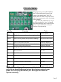
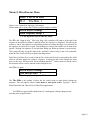
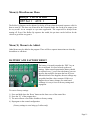
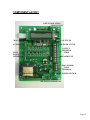
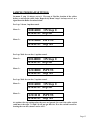
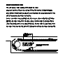
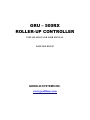
GRU – 500RX
ROLLER-UP CONTROLLER
INSTALLATION AND USER MANUAL
DATE ISSUED 2/07
GOODLIN SYSTEMS INC.
www.goodlinsys.com
CONTENTS
Introduction --------------------------------------------------------------- Page 2
Installment procedures --------------------------------------------------- Page 2
Solenoid Power Setting -------------------------------------------------- Page 3
Wiring ---------------------------------------------------------------------- Page 4
Programming -------------------------------------------------------------- Page 5-11
Battery and Factory Setting ---------------------------------------------- Page 11
Component Layout ------------------------------------------------------- Page 12
Sample Program settings ------------------------------------------------- Page 13
Roller Location Switch --------------------------------------------------- Page 14
INTRODUCTION
The GRU-500-RX is a programmable roller up controller. It has more flexibility
than any off the shelf roller controller. It can be programmed for a rear wheel or
front wheel push conveyor setup. The system can bring up the amount of rollers
wanted, in any order up to 9 rollers.
The GRU-500-RX has a built in LCD readout screen and keypad that makes it
very user friendly. It allows onsite editing of the function programming. By setting
a few simple parameters the GRU-500-RX can be made to sequence any
combination of rollers. If in the future, the roller up function needs to be changed,
the programming can be altered as needed. Since the parameter programming is
battery protected, it is unaffected by power loss.
INSTALLMENT PROCEDURES
1.) PICK OUT A GOOD TIME FOR INSTALLATION! An evening that has a relatively
slow next day is preferred in case of trouble or complications.
2.) TEST THE CARWASH FOR PROPER WORKING ORDER! MAKE SURE THE
EQUIPMENT WORKS BEFORE WORKING ON IT! This way if something is
wrong after you start you can tell it’s the equipment and not the installation of the
new system.
3.) Find a suitable place for the control box. If a Roller Location Switch (GS-RLS) is
used make sure the sensor cord can reach between the sensor and the control box.
4.) Mount the control box and the Roller location switch according to directions if any.
5.) Make sure you have a constant 110vac power for this system. It is recommended that
this be a constant circuit, and NOT INTERLOCKED. It is recommended that power
to and on the control box is kept on at all times. The heat generated by the
transformer will keep the control box free of condensation. It is highly
recommended to not have any piping run into the top of the control box. This
prevents water from running down the pipe and into the control box. Even if the pipe
is sealed from the outside, the condensation that accumulates on the inside of the pipe
might bring water down into the control box!
6.) Wire according to wiring diagrams and local electrical codes.
7.) BEFORE APPLYING POWER RECHECK YOUR WIRING AND CHECK IT
AGAINST THE WIRING DIAGRAMS. NOTE: THERE ARE SOME VERY
IMPORTANT DIFFERENCES BETWEEN THIS ROLLER-UP CONTROLLER
AND OTHER UNITS FROM GSI.
8.) Test with the power the working of the unit along with Inputs and the solenoid output.
9.) Program unit with the Programming instructions.
10.) After installation test this unit and the car wash for proper operation. Fill out the
charts of the programming and put this Manual in a safe place for future reference.
Page 2
Solenoid Power and Aux Output Setting
The solenoid for the roller up forks is powered by the control board. No outside
power is to be used on these circuits!! The solenoid can be 110vac or
24vac depending on the position of the output terminal setting located on the bottom of
the main board.
Seen here for 24vac, the power is set to come from
the on board transformer. It can drive up to 1 amp of
power for the external outputs. This is plenty for an
air solenoid and a control relay.
Seen here for 110vac, the 110vac that powers the
Roller-Up controller will be used for the external
outputs. This circuit should not exceed 4 amps total.
For the long life of the controller it is better to
activate a relay for external lighting if the aux is used
in this manner. Solenoids for a Prep/soap arch should
not need an interfacing relay. However a fuse should
be used on it so it can not exceed 4 amps.
This is easy to change, simply pull off the terminal
strip from the board. The Terminal is a 2 piece that
can be separated by sliding the two apart. Put them
together for 110vac or 24vac as shown above
The Outputs for both the Solenoid and the Aux
should never have any outside power source
applied to them Severe Damage to the controller
could result!! GSI will not be liable of repair or
replacement needed out of any damage of this
type.
Page 3
Wiring Diagrams - Field Wiring.
CAUTION!!
No External Power is to be applied to the 1-8 terminal block (Interface).
Only the Main 1-3 terminal for the 110vac input is to have External power applied.
This 110vac should not be an interlocked circuit.
See the section of Solenoid Power and Aux Output Setting for the solenoid
and Aux output power settings.
Remember: No Power to be put into any terminals of the Interface Terminal Block.
The Outputs for both the Solenoid and the Aux should never have any outside power
source applied to them Severe Damage to the controller could result!! GSI will not be
liable of repair or replacement needed out of any damage of this type.
Page 4
PROGRAMMING
The programming on the GRU-500RX is
done by the program pads located in the
center of the control board. The LCD
display shows the menu screens that can be
used to set the parameters of the functioning
of the controller.
The mini pad push buttons are easy to
use. When depressed a ‘beep” will sound
from the main Beeper for a second. See the
menus on more information on the pad
functions for programming.
Pad Tag
MENU
Function
Notes
ITEM
Can be used always to
move to next set
Toggles from a menu down to the settings for editing Only used in some menus
FIELD
Moves Cursor position (when position is blinking)
Only used in some menus
UP
Help
Up Arrow key used to increase a number value or
move to next value of the item
Down Arrow key used to decrease a number value
or move to next value of the item
Brings up a help text (if available)
Used to change
parameters displayed
Use to change
parameters displayed
Only used in some menus
F1
Special function
Not used
F2
Special function
Not used
F3
Special function
Not used
F4
Special function
Not used
DEL
To Delete or Reset a value or entry
Not used
ADD
Set a value to memory
Not used
(automatically done)
DOWN
Toggles through the LCD Program Menus
NOTE: All the settings in the menus and the ‘Auto mode’ are backed
up by the on board battery and do not have to be re-entered upon
power loss. The program memory is a flash type and does not
require the battery.
Page 5
Menus and settings
Using the Menu Key, the LCD will display different information. On some of the screens Data
can be entered and changed to set the operation parameters of the Roller-up functioning.
Menu (1) Beginning and Running Mode
GOODLIN SYSTEMS INC
GRU-500RX VER GRX.1
This displays as the controller is booting up and should be set back to this menu while
unit is being used normally.
When placed in Automatic mode the system will allow the tire switch to start the roller-up
sequence. The LCD display for Menu (1) will change to this:
Auto mode is ACTIVE
GRU-500RX VER GRX.1
To Toggle between Automatic mode and Manual mode for activation of sequence push the
“Automatic On Enter” button.
Page 6
Menu (2) Roller Fork Sequence and Reset setting
010140000 ON Step 0
123456789 Step Set
The upper half displays the items activated on the sequence steps of the Roller-Up function
and what step the controller is presently on. The lower half of the display is referencing the
Steps 1-9 and what the menu does. If this menu is left on during operation, as the controller
sequenced the ON Step # would change. This would be according to what step the sequence
was on. This is very useful for seeing how the operation is working as the reference of what
is to be activated is displayed with the STEP the sequence is on. For our example here:
0= No outputs on this step (good for finding the roller before we call it up)
1= Roller-Up Solenoid on this step
2= Roller-Up Solenoid and Aux Output on this step
3= Only Aux Output on this step
4= Unit reset called (end of sequence) when we get to this step
Changing the values of the steps is done with the ‘UP’ and the ‘DOWN’ keys. To move
from one Step to another use the “FIELD’ key. Using the ‘FIELD’ key the sequence
number that is being edited will flash. * The “FIELD” key might have to be pressed
before you see any digits flashing. It moves the cursor from left to right.
The Screen as shown above would do this operation as follows:
12345-
Do nothing, this is recommended for Roller-Guard function
Bring up one roller. This would be the 1st Roller to come up
Drop forks and let one pass. Rollers are down while it is on this step.
Bring up another Roller. Activate forks up again for last roller.
Reset the sequence.
A simple 2 rollers and then reset might look like this:
011400000 ON Step 0
123456789 Step Set
2 rollers up, then down, 2 follow with the Aux output at the end might look like this:
011012400 ON Step 0
123456789 Step Set
Page 7
Menu (3) Inputs to allow next sequence
111100000 INPUTS
123456789 Step Set
This displays the items activated on the sequence steps of the Roller-Up Function
0 = No inputs can move the sequence (only used at the not used steps)
1= Roller Location Switch
2= Tire Location Switch
3= Roller Location Switch or the Tire Location Switch
Changing the values of the steps is done with the ‘UP’ and the ‘DOWN’ keys. To move
from one Step to another use the “FIELD’ key. Using the ‘FIELD’ key the sequence
number that is being edited will flash.
The Screen as shown above would do this operation:
1- Wait till we get a signal from the Roller Location Switch then move to next step
2- Wait till we get a signal from the Roller Location Switch then move to next step
3- Wait till we get a signal from the Roller Location Switch then move to next step
4- Wait till we get a signal from the Roller Location Switch then move to next step
If we wanted the Tire Switch to activate for the step #3 it would be:
112100000 INPUTS
123456789 Step Set
This would make the system wait for the tire switch to input before it brought up the last
roller. The sequence of Stepping shown here would be:
1- Wait till we get a signal from the Roller Location Switch then move to next step
2- Wait till we get a signal from the Roller Location Switch then move to next step
3- Wait till we get a signal from the Tire Switch then move to next step
4- Wait till we get a signal from the Roller Location Switch then move to next step
Between Menu 2 and Menu 3 settings the system can control any roller up dolly sequence
in any order!
IMPORTANT!! For any step that is used you must have an input to move to
the next step 1, 2, or 3. Never leave one of the steps on 0 or the sequence
will stop and appear to be locked up.
Unused steps can be set to 0 for reference Factory default is (1).
Page 8
Menu (4) Input Timers for De-Bouncing
Timers ITEM to edit
RLS 200 6 TS 30 8
This displays the timer settings on the Roller Location Switch and the Tire Switch
RLS stands for the Roller Location Switch and the first # is the time set that must elapse before
the system will accept a signal from the RLS. This is useful in de-bouncing or ignoring a signal
produced by a 2 roller dolly hitting the switch twice. The second # is the time that the signal
has to stay on to be accepted. This helps in elimination of arc bounce in some switches or to
help make sure we are signaling off the main roller of the dolly.
TS stands for the Tire Switch and timers are set the same as the ones for the RLS.
Notice: There is no cursor or Flashing here. That is because we use the ITEM key to scroll
down the submenus to edit the timers. Once in the sub menu the LCD will display to use the
Arrow (‘UP’ and “DOWN”) keys to change the settings. At any time pressing the MENU key
will move to the next Main scrollable menu, Menu (5). Any changes made to the settings are
stored automatically at the time of the change. For each time the up/down button is pushed the
value of the submenu item will change accordingly. Holding down the up/down keys will in a
few seconds, rapidly add/sub the value by 10’s.
Since we see 4 timers here, there are 4 sub menus:
Off the main (above menu) Hit ITEM key and the display would be:
Arrow Keys to change
RLS TD Off 200 ms
Use the up/down keys to edit the value
Hit ITEM key again:
Arrow Keys to change
RLS TD On 6 ms
Use the up/down keys to edit the value
Hit ITEM key again:
Arrow Keys to change
TLS TD Off 30 ms
Use the up/down keys to edit the value
Hit ITEM key again:
Arrow Keys to change
RLS TD On 8 ms
Use the up/down keys to edit the value
Hit ITEM key again and the Main Menu (4) would appear with any changes made showing in
the respected timers.
Page 9
Menu (5) Miscellaneous Menu
Misc ITEM to edit
JS 2 Tire Hits 1
Since we see 2 items here, there are 2 sub menus:
Off the main (above menu) Hit ITEM key and the display would be:
Arrow Keys to change
Stack Sequence Jump 2
Use the up/down keys to edit the value
The JS is the “Jump to Step”. This is the Step # the controller will jump to at the end of the
sequence if the Roller-Up button is pushed before the sequence is completed. This allows the
system to ‘Stack’ the sequence to start sending another car without having to reset and wait for
the sequence to restart all over again. Thus loading one vehicle after another can be done more
quickly. Waiting for sequence to end and then hitting the Roller-up button is not necessary.
The system will only accept this input to be “stackable’ between steps 3 and 9. On Automatic
mode the Tire Switch will also set up this Stacking feature.
Field Note: If a Photo Eye is used to find the Tire of the vehicle and it is activated by the called
rollers it will false trigger the ‘Jump to’ sequence. To adjust for this set the Jump to the same
step # as the reset. The auto stack will be disabled and the 2nd vehicle must wait for the end of
the sequence before it can be entered on the track photo-eye.
Hit ITEM key again:
Arrow Keys to change
Tire Hits on Auto 1
Use the up/down keys to edit the value
The Tire Hits is the number of times the tire switch needs to input before starting the
sequence. This only applies when in Auto mode or Auto mode Active. Typically, 1 hit for
Front Wheel Pull and 2 hits for Rear Wheel Push applications.
Hit ITEM key again and the Main Menu (5) would appear with any changes made
showing in the respected items.
Page 10
Menu (6) Miscellaneous Menu
Delays ITEM to edit
OFF Sol 1 AUX 1
The Roller-Up Outputs can be adjusted to delay off from when the normal sequence calls for
them to turn off. This does not do much for the Solenoid (forks), but for the Aux output it can
be very useful. As an example as a pre-rinse application. The output will be delayed from
turning off. Even if the Roller-Up sequence has ended, the pre-rinse can be held on for the
vehicle to get all the way past it.
Menu (X) Menus to be AddedOther Menus may be added to the program. There will be a separate instructions on what they
do and how to edit them.
BATTERY AND FACTORY RESET
The battery is located just under the ‘DEL’ key on
the circuit board. It is used to back up the user
settings. Under normal operation the battery should
be replaced every 5 years. Once the battery goes out
the user data would be lost upon the loss of power.
When this kind of loss happens, the user settings may
get garbled and the values corrupted. If this ever
happens due to battery change or a main board
exchange it is easy to reset to factory settings and
reprogram.
To reset to factory settings:
1)
2)
3)
4)
Press and hold down the ‘Reset’ button on the front cover of the control box
Press the ‘F1’ of the program keys.
The unit will now reset all the variables to factory setting.
Reprogram to the wanted configuration.
(Factory settings is set to bring up 2 rollers only)
Page 11
COMPONENT LAYOUT
INPUT INDICATION
TIRE SWITCH
RLS SWITCH LCD SCREEN
MAIN CPU BOARD__________
-----AUX FUSE
AUX INPUTS
MAIN
DOOR
TERMINAL
___________SOLINOID ACTIVE
PROGRAM KEYS
OUTPUT
__ _____TERMINAL
STRIP
_________SOENOID FUSE
BATERY
MAIN POWER
______ INPUT
TERMINAL
SEC FUSE ---TRANSFORMER
MAIN POWER SWITCH
MAIN FUSE----
|
OUTPUT POWER
SELECTION TERMINAL
Page 12
SAMPLE PROGRAM SETTINGS:
On menu 2, step 1 is always set to 0. We want to Find the location of the rollers
before we activate the roller forks. Respectively Menu 3 step 1 is always set to 1 as a
signal from the Roller Location Switch.
For 1 up, 2 down, 1 up then cancel.
Menu 2 =
010014000 ON Step 0
123456789 Step Set
Menu 3 =
111111000 INPUTS
123456789 Step Set
For 1 up, Wait for rear tire, 1 up then cancel.
Menu 2 =
010140000 ON Step 0
123456789 Step Set
Menu 3 =
112110000 INPUTS
123456789 Step Set
For 1 up, Wait for rear tire, 2 up then cancel.
Menu 2 =
010114000 ON Step 0
123456789 Step Set
Menu 3 =
112111111 INPUTS
123456789 Step Set
At anytime, the step settings after the reset are ignored. So even if the roller switch
could move the steps 7, 8 and 9 it will not get that far. If no tire switch is used for
locating the rear tire, menu 3 can be all 1’s
Page 13