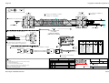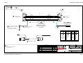
1
Quin Systems Limited
Qmanager
Installation Manual
Issue 4 Amdt A
December 2008
(MAN442)
Quin Systems Limited
Qmanager
Installation Manual
Issue 4 Amdt A
December 2008
(MAN442)
Important Notice
Quin Systems reserves the right to make changes in the products described in this
document in order to improve design or performance and for further product
development. Examples given are for illustration only, and no responsibility is assumed
for their suitability in particular applications. Reproduction of any part hereof without
the prior written consent of Quin Systems is prohibited.
Although every attempt has been made to ensure the accuracy of the information in this
document, Quin Systems assumes no liability for inadvertent errors.
Suggestions for improvements in either the products or the documentation are
welcome.
Relevant Directives
The product is designed to be incorporated into a system for the control of machinery,
and needs external equipment to enable it to fulfil this function. It must not be relied
upon to provide safety-critical features such as guarding or emergency stop functions.
It must not be put into service until the machinery into which it has been incorporated
has been declared in conformity with the Machinery Directive 89/392/EEC and/or its
relevant amendments.
The installation instructions in this manual should be followed in constructing a system
which meets requirements.
The product has been tested in typical configurations, and meets the EMC Directive
89/336/EEC, when fed from power supplies which meet 89/336/EEC and 92/31/EEC.
The product uses only low voltages, and is therefore exempt under 73/23/EEC as
amended by 93/68/EEC.
The product as normally supplied has low voltages accessible to touch, and must be
mounted within a suitable cabinet to meet any required IP rating to BS EN 60529.
Issue 4
Qmanager Installation Manual
Copyright Notice
Copyright © 2008 Quin Systems Limited. All rights reserved.
Reproduction of this document, in part or whole, by any means, without the prior
written consent of Quin Systems Limited is strictly prohibited.
Version History
Issue
Date
Update Reason
1
Aug 2003
2
June 2004
JTAG, Anybus testing
3
July 2007
minor corrections
4
Sept 2008
Add QLC and Ethercat info
Amendment Record
Date
Dec 08
Issue
4
Amdt.
A
Pages
11
Copyright © 2008 Quin Systems Ltd.
By
RF
Reason
RS485 signal names
Page i
Qmanager Installation Manual
Page ii
Issue 4
Copyright © 2008 Quin Systems Ltd.
Issue 4
Qmanager Installation Manual
Contents
1.
Introduction
5
2.
Unpacking and Inspection
6
3.
System Specifications
3.1
Mechanical Specification
3.2
Environmental specification
3.3
Power supply specification
3.4
Electrical specification
3.5
Relevant directives
7
7
7
7
8
8
4.
Mechanical Installation
9
5.
Connections
5.1
Serial Data
5.2
Process Logic and Supplies
10
11
12
6.
Electrical Installation
6.1
General
6.2
Mains Power supply
6.3
Earth connections
6.4
Digital inputs and outputs
14
14
15
15
16
7.
Safety - Using Guards and Limits
17
8.
Testing the System
8.1
General
8.2
Serial port
8.3
Digital signals
18
18
18
19
9.
Electrical Details
9.1
Isolated input and output circuits
20
20
10.
Board Configurations
10.1 General
10.2 Anybus board
21
21
23
11.
PTS System Configuration
11.1 Configuration Commands
11.2 Ports and Interfaces
24
24
26
12.
Diagnostics and Tests
12.1 SRV400 Flashboot Sector
12.2 BDM port access
12.3 CPLD Download
12.4 JTAG
12.5 PTS Language Diagnostics
29
29
32
33
33
34
A.
Standard Cable Drawings
A.1
Introduction
35
35
Copyright © 2008 Quin Systems Ltd.
Page 1
Qmanager Installation Manual
Page 2
Issue 4
Copyright © 2008 Quin Systems Ltd.
Issue 4
Qmanager Installation Manual
Figures and Tables
Figure 1.
Fixing centres for the Servo Controller.
Figure 2.
Connector Layout
10
Table 1.
RS232 port A, port B connections
11
Table 2.
RS485 port B connections
11
Table 3.
CANbus connections
12
Table 4.
Back screw terminal connections
13
Figure 3.
General installation arrangement.
14
Figure 4.
Input and output circuits
16
Figure 5.
Testing the digital signals.
19
Figure 6.
Isolated Input and output circuits
20
Figure 7.
Qmanager jumper locations
22
Table 5.
Cable Cross-reference
35
Copyright © 2008 Quin Systems Ltd.
9
Page 3
Qmanager Installation Manual
Page 4
Issue 4
Copyright © 2008 Quin Systems Ltd.
Issue 4
1.
Qmanager Installation Manual
Introduction
This document is the Installation Manual for the Qmanager, a member of the Quin
Systems digital Programmable Transmission System (PTS) range.
Machine Manager units are used in SERVOnet based PTS and QLC (soft PLC)
systems. These are distributed systems consisting of a number of servo motor axis
controllers and a manager or host unit providing overall system control, external
communications and user interfaces. The manager is linked to the axis controller
modules via SERVOnet, a high speed network system based on either CANbus or
EtherCAT.
Three models of manager are available, and this document includes installation details
for the newest of the three, the Qmanager. The Qmanager has a MPC555 processor,
with 4 Mbyte or more of flash memory for firmware, and 2 Mbyte ram space available.
The flash includes the system firmware. It is programmed via an RS-232 serial port or
an Ethernet link, and uses 256k of flash memory for configuration, user program and
map retention. 1 Mb of RAM has battery hold-up; some of this is used for variables
(approximately 10000 variables or array elements). The processor uses a 32-bit bus at
40MHz.
PLEASE READ THIS MANUAL BEFORE INSTALLATION.
It is very important that the guidelines for installation are observed, otherwise damage
to the system or to the machine may occur. Quin Systems Limited accept no liability
for damage or costs arising from incorrect or inadequate installation of the systems, or
from incorrect programming of the system for the required application. Digital control
systems are not simple, but can be used successfully to control industrial machinery and
provide great improvements in reliability, performance and flexibility.
Copyright © 2008 Quin Systems Ltd.
Page 5
Qmanager Installation Manual
2.
Issue 4
Unpacking and Inspection
Inspect the packaging for external signs of damage, if possible before signing the
delivery receipt, as this may indicate that it has been mishandled in transit. When
unpacking the system, keep all the packaging materials if possible. If it is necessary to
ship the system to another site, or to return it for service, the original packing can be
re-used.
Inspect the system carefully when it is unpacked. Check for any loose parts, any circuit
boards loose in their card guides, cables not connected, or any bending of the case or
chassis.
If any defect or damage is suspected, do not connect power to the system. Notify
the carrier immediately, and contact your sales office or the Quin Systems Service
Department:
Quin Systems Limited
Service Department
Oaklands Business Centre
Oaklands Park
Wokingham
Berkshire RG41 2FD
England
Telephone
Fax
Email
Web site
Page 6
+44 (0)118 977 1077
+44 (0)118 977 6728
[email protected]
[email protected]
http://www.quin.co.uk/index.html
Copyright © 2008 Quin Systems Ltd.
Issue 4
Qmanager Installation Manual
3.
System Specifications
This section gives the overall specifications of the system, including mechanical details
and environmental requirements.
3.1
Mechanical Specification
The dimensions of the Qmanager are as follows:
Height
Width
Depth
Weight
314 mm
66 mm (120 mm including connectors)
199 mm
2 kg
Sufficient additional clearance must be left above the top connectors and in front of the
serial port connectors for plugs and cables, and adjacent to the terminals for cable
connection. The system is designed to be mounted in the normal orientation with the
circuit board vertical, to allow cooling air circulation by convection. If the unit cannot
be mounted with the board vertical, then a fan must be fitted to blow air over the unit.
3.2
Environmental specification
Temperature:
storage
0 to 70°C
operating
0 to 40°C
Relative humidity: 20 to 80% non-condensing
The system may be operated at higher ambient temperatures, but will require additional
cooling such as forced air ventilation in order to do so.
3.3
Power supply specification
The power supply requirement for the Qmanager system is nominally 24V 0.35A d.c.
The system accepts a supply voltage in the range 19–28V d.c. The power supply input
is protected against reverse voltage connection.
Additional power supplies are required for the external digital input and output signals.
The digital inputs and outputs use 24V d.c. for compatibility with PLC systems. The
input and output lines are fitted with clamp diodes, and a diode provides some
protection against reverse connection of the i/o supply. CANbus SERVOnet needs 12V
d.c., and this must never be reverse-connected.
The unit includes a battery for storage of process variables and axis position. The
retention period without other power is typically several weeks. The battery (NiMH 2.4
volt Varta type 2/15H) should be replaced every 5 years, with a new blob of silicone
sealant to ensure retention in the socket: Quin can undertake this task.
Copyright © 2008 Quin Systems Ltd.
Page 7
Qmanager Installation Manual
3.4
Issue 4
Electrical specification
The electrical characteristics of the Qmanager module are listed here.
External power supplies :
Digital i/o supply
Logic supply
SERVOnet/CANbus
+24V
+24V (19 to 28V, 350mA)
+12 V nominal (7 to 13 V range)
Digital inputs :
Voltage rating
Input current
typical:
Threshold voltage
Reverse voltage
Isolation voltage
+24V nominal
7–10 mA
10–16V
24V maximum
250V a.c. peak or d.c.
Digital outputs :
Saturation voltage (output on)
Load current per signal
Load current per group of 8
Isolation voltage
3.5
1.9V maximum (at full load current)
500 mA maximum
2 A maximum
250V a.c. peak or d.c.
Relevant directives
The product is designed to be incorporated into a system for the control of machinery,
and needs external equipment to enable it to fulfil this function. It must not be relied
upon to provide safety-critical features such as guarding or emergency stop functions.
It must not be put into service until the machinery into which it has been incorporated
has been declared in conformity with the Machinery Directive 89/392/EEC and/or its
relevant amendments.
The installation instructions in this manual should be followed in constructing a system
which meets requirements.
The product has been tested in typical configurations and meets the EMC Directive
89/336/EEC, when fed from power supplies which meet 89/336/EEC and 92/31/EEC.
The product uses only low voltages, and is therefore exempt under 73/23/EEC as
amended by 93/68/EEC.
The product as normally supplied has low voltages accessible to touch, and must be
mounted within a suitable cabinet to meet any required IP rating to BS EN 60529.
Page 8
Copyright © 2008 Quin Systems Ltd.
Issue 4
4.
Qmanager Installation Manual
Mechanical Installation
The Qmanager system has mounting holes on the rear metal plate, for fixing to the
electrical panel inside a cabinet. The unit is fixed with three M5 bolts through holes at
the top and bottom of the unit. The fixing centres for these bolts are shown in the
diagram below. Note that the bottom fixing hole is slotted and the top fixing holes are
keyhole shaped to allow the unit to be slotted over the heads of suitable mounting bolts.
8.3
Terminal rail
connections
this side
298.8
314.1
φ5.2 (M5 clearance)
60
31.5
15.5
Dimensions in mm
47.5
63
Figure 1. Fixing centres for the Servo Controller.
The I/O terminals are in two parts, for ease of wiring, and the removable part includes
cable-ties. They protrude about 60 mm, and need adequate space for cable routeing.
Similarly the plugs for the fieldbus at the top need space for cables, and there should be
75 mm clear above and below the unit for cooling air.
Copyright © 2008 Quin Systems Ltd.
Page 9
Qmanager Installation Manual
5.
Issue 4
Connections
The Qmanager has several connectors.
Top view
Comms expansion
T1 1
LED1
LED8
T2 1
Back View of case
IR
LED9
Front panel
Ethernet
S3
Port
A/B
LED16
T3 1
LED17
S5
CAN
open
LED24
T4 1
T10
S4
1
SERVO
net
1
T9 1 T8
1
T7
1
T6
1
T5
Figure 2. Connector Layout
•
9 way double D-type socket S3 for the RS-232 programming terminal port A
(left), and for the RS-485 data port B (right).
•
9 way double D-type plug/socket S4 for the SERVOnet high speed network,
based on CANbus.
•
9 way double D-type plug/socket S5 for the CANopen device interface or intermanager linking with SynchroLink, again on CANbus.
•
8 way RJ45 socket SK4 for Ethernet 10baseT or 100baseTX.
Page 10
Copyright © 2008 Quin Systems Ltd.
Issue 4
Qmanager Installation Manual
•
3 off 10 way two-part screw terminal connectors T1 T2 and T3 for the isolated
24V digital inputs and outputs.
•
2 way two-part terminal connector T4 for 24 volt I/O supply input.
•
space for 10 way and 5 way two-part screw terminal connectors T5 T6 T7 T8
and T9 for expansion analogue inputs and outputs.
•
6 way two-part screw terminal connector T10 for the input of power for the unit
supply volts.
5.1
Serial Data
The RS-232 serial port A on the controller uses the left half of socket S3. The pin
connections to this are shown below.
S3 pin no.
Signal
1
S3 pin no.
Signal
6
2
/TXD
7
RTS
3
/RXD
8
CTS
4
9
5
GND
Table 1: RS232 port A, port B connections
It is important that static charge from portable equipment is not discharged by
connection to the serial ports: the electronics may be damaged and machine operation
affected. Equipment should be earthed by prior connection of a ground lead, and we
recommend use of cable CBA13 007 and initial connection of its earth tails to PC
chassis and a panel earth terminal.
The serial port B for the Operator’s Panel or Modbus interface uses the right half of
socket S3. The RS232 connections to this are as Table 1, RS-485 as Table 2 below.
S3 pin no.
Signal
S3 pin no.
Signal
1
High termination
6
+Vbias
2
TXD (= TxB)
7
/TXD (TxA)
3
RXD (= RxB)
8
/RXD (RxA)
4
Low termination
9
5
GND
Table 2: RS485 port B connections
Quin can supply various interface cables.
Copyright © 2008 Quin Systems Ltd.
Page 11
Qmanager Installation Manual
Issue 4
The Qmanager has two double 9 way D plugs and sockets for two separate CANbus
interfaces. The SERVOnet high speed network ports use D-type plug and sockets S4,
parallel-connected; this allows units to be daisy chained together easily with standard
cables. The second interface similarly uses parallel-connected plug and socket S5,
again allowing unit chain or power feed.
The connections for the CANbus interfaces on the front panel 9 way plugs are shown
below. The plug and socket are connected pin-to-pin, to allow a simple daisy chain
connection. Note that these comply with the CAN in Automation (CiA) draft standard
DS102 Version 2.0, CAN Physical Layer for Industrial Applications, but with
additional signals used for error detection.
Pin no.
Signal
Pin no.
Signal
1
LINK1
6
CAN_0V
2
CAN_L
7
CAN_H
3
CAN_GND
8
CAN_ERR
4
LINK4
9
CAN_V+
(7–13V)
5
CAN_SHLD
(screen)
Table 3: CANbus connections
Note that each CANbus interface requires an external power supply to power the
isolated network transceivers, each connected separately via the D type connectors.
Recommended cable pairing and linking for termination and break-detection are given
in the appendix on drawing QDV-2-2-007, and standard cables are available under
stock code CBA10 003. For further information refer to the SERVOnet handbook.
The Qmanager also provides an Ethernet interface using a twisted pair (10baseT or
100baseTX) interface. This uses an 8 way RJ-45 socket, with the transmit pair on pins
1 and 2, receive on 3 and 6, as standard. With EtherCAT netwotk this connects to the
drives, with an Anybus Ethernet card for a programing port.
5.2
Process Logic and Supplies
Terminal blocks T1 to T4 are used for the host-level digital inputs and outputs, and T10
for power input. T1 and T2 carry 16 digital inputs: inputs 8:1 to 8:8 and 9:1 to 9:8; T3
gives 8 digital outputs, 8:1 to 8:8. All the 0 volt i/o (T1.10, 2.10, 3.10, and 4.2) and all
the 24 volt i/o pins (T1.1, 2.1, 3.1 and 4.1) are commoned, for ease of sensor wiring.
They are optically isolated from other supplies.
Note that the 24V power supply input is not isolated from the internal logic supplies,
and the 0V supply connection should be earthed.All the screen connections are linked
together to allow a single earth connection for all the cable screens. They are connected
to the metalwork and the D-type connector shells, but are not connected to the system
internal 0V supply. A clean separate earth connection is normally required to the 0V
supply on terminal T10.2 or T10.5.
Page 12
Copyright © 2008 Quin Systems Ltd.
Issue 4
Qmanager Installation Manual
The next table shows the connections on all the two-part screw terminal blocks at the
back of the unit.
Back screw terminals
Listed from top to bottom
Signal
1.1
0V i/o
1.2
Input 8:1
1.3
Input 8:2
1.4
Input 8:3
1.5
Input 8:4
1.6
Input 8:5
1.7
Input 8:6
1.8
Input 8:7
1.9
Input 8:8
1.10
+24V i/o
2.1
0V i/o
2.2
Input 9:1
2.3
Input 9:2
2.4
Input 9:3
2.5
Input 9:4
2.6
Input 9:5
2.7
Input 9:6
2.8
Input 9:7
2.9
Input 9:8
2.10
+24V i/o
3.1
0V i/o
3.2
Output 8:1
3.3
Output 8:2
3.4
Output 8:3
3.5
Output 8:4
3.6
Output 8:5
3.7
Output 8:6
3.8
Output 8:7
3.9
Output 8:8
3.10
+24V i/o
4.1
+24V i/o
4.2
0V i/o
10.1
10.2
0V supply
10.3
Screen/earth termination
10.4
+24V unit supply
10.5
0V supply
10.6
Screen/earth termination
Table 4: Back screw terminal connections
Copyright © 2008 Quin Systems Ltd.
Page 13
Qmanager Installation Manual
Issue 4
6.
Electrical Installation
6.1
General
This section gives some guidelines for the electrical installation of the control system.
The diagram below shows a typical installation, and will be used to highlight specific
areas of interest in the following sections. Note that this is only a very simplified sketch,
not a full installation wiring diagram. Details such as isolators, contactors and other
switching arrangements are not shown but in most cases should be used. Please refer to
the motor and drive manufacturer’s instructions for further details on electrical
installation.
Equipment cabinet
3 phase
supply
Noise
filter
Motor
Drive
R
S
T
+24V
power supply
Control
system
Encoder
Isolation
transformer
Earth
Figure 3. General installation arrangement.
•
Use separate trunking to keep all low voltage signal cables (encoder, resolver,
command signal) away from three-phase, high current, or high voltage wiring.
Page 14
Copyright © 2008 Quin Systems Ltd.
Issue 4
6.2
Qmanager Installation Manual
Mains Power supply
The Qmanager requires +24V d.c. provided by an external power supply. The mains
input may be taken from the same three phase mains used for the motors and drives, but
care must be taken to avoid introducing noise onto the supply to the control system.
For best results, follow the recommendations below.
•
Use an isolation transformer and a line filter in the mains supply to the system.
In some cases a line conditioner may be required.
•
Do not tie the input and output cables from the line conditioner or filter
together, or run them close together in a conduit or cable duct.
•
Do not tie the three phase cables or the single phase supply cables together with
any low voltage signal cables.
6.3
Earth connections
Earthing is very important in any electrical installation. It is an essential safety measure
to prevent electric shock in case of any failure of the equipment, and is also used for
screening between different units. It provides a ground reference point for all units in
the system. Incorrect earth connection can result in erratic operation due to noise or
earth loops, or may prevent the system from operating at all. These problems can be
avoided by careful arrangement of the earth connections, and by such techniques as
isolation.
•
The earth connections from any isolation transformer and the power supply
filter should be made in heavy gauge wire. All the earth connections should be
connected together at one point, preferably on the electronics cabinet chassis.
•
Do not tie the earth wires together with any low voltage signal cables, or run
them close together in the same conduit or cable duct.
•
All screened cables should have their screens connected directly to earth, not via
the system 0V power supply. This is very important, as otherwise noise and
transients picked up in the screen will pass through the system, instead of being
dissipated directly to earth.
•
Note that the 24V power supply input is not isolated, and an earth connection
should be made at the 0 volts (negative side) of the power supply. This avoids
the internal paths of the Qmanager having to provide the earth connection for
the power supplies.
Copyright © 2008 Quin Systems Ltd.
Page 15
Qmanager Installation Manual
6.4
Issue 4
Digital inputs and outputs
The Qmanager provides sixteen digital inputs and eight digital outputs, all fully
isolated. These may be used for several functions, such as monitoring pushbuttons or
guards, controlling external solenoids or relays (subject to the quoted current limits), or
signalling to a programmable logic controller. The isolated interface allows +24V logic
signals to be used.
This diagram shows typical input and output circuits, with any protection components
shown as well.
+24V
Input 1
PNP sensor
0V
0V I/O
Fast Input circuit
World .. Qmanager
+24V
Input 2:1
Pushbutton
0V
0V I/O
Standard Input circuit
Qmanager .. World
+24V
+24V I/O
Output 1
Load
0V
0V I/O
Output circuit
Figure 4. Input and output circuits
* Note the commutating diode local to the output load. This is important for avoiding
interference from inductive loads: do not rely on the small protection diode in the
Qmanager.
Page 16
Copyright © 2008 Quin Systems Ltd.
Issue 4
7.
Qmanager Installation Manual
Safety - Using Guards and Limits
All machines should include comprehensive safety features. This is essential both for
normal safety considerations, and to comply with Health and Safety requirements. It
can also prevent any unwanted interference with the machine while it is running.
All moving machinery must be guarded so that it cannot be reached by anybody while
in motion. The guards should be fitted with guard switches or sensors, connected so as
to immediately cut power from the motors when any guard is opened. On some
machines, it may be useful to lock the guards closed by means of a solenoid to prevent
them from being opened while the machine is running. This allows the machine to
detect any attempt to open a guard and shut down the machine cleanly before unlocking
the guard and allowing it to open.
Motors which have constraints or limits on their range of motion should be fitted with
hard wired limit switches. These should cut power from the motors if any motor goes
outside its limits of travel. The machine must also have one or more locking emergency
stop pushbutton switches, accessible from several positions around the machine.
Anyone operating or working on the machine must be able to instantly stop the machine
at any time by hitting an emergency stop switch.
Guards, emergency stop and limit switches may be connected into the PTS or QLC
motor control systems, by using the digital input lines. However, the programmable
input functions on these units should only be used in addition to the conventional hard
wired guard and limit switches, not to replace them. The digital inputs can be used to
trigger a smooth shutdown sequence, or to generate a limit switch error and shut down
immediately. The control system can then remove power from the motors and drives if
required, under software control, by using a digital output line to switch the motor
supply contactors. In all installations the limit switches and guard switches MUST
remove all electrical power from the motors and drives within a reasonable time,
independently of any action of the control system. If power is removed from the
control system, then again all power must be removed from the motors.
Note that in most cases, it is not necessary to remove power from the control system,
only from all the high power equipment. If power to the control system and encoders
can be maintained even when the motors and drives are shut down, then the system does
not lose any position information. This can allow the machine to start up again much
more quickly than if the control system is powered off as well, since the machine does
not need to execute a complete initialization before it can be restarted.
For more information on programming the Qmanager and system for limit switch
inputs and user defined functions, please refer to the descriptions of the DL and DI
commands in the Input/Output Configuration section of the Reference Manual.
Copyright © 2008 Quin Systems Ltd.
Page 17
Qmanager Installation Manual
8.
Testing the System
8.1
General
Issue 4
This section describes some simple test procedures for some parts of the PTS or QLC
systems. These do not comprise a full system test, but may be useful to verify the basic
operation of the system, the motor and the encoder.
All these tests require the use of a computer terminal with an RS-232 serial port. A laptop computer and terminal is generally used. Some tests require additional test
equipment, as given below.
8.2
Serial port
The system prints characters via the RS-232 serial port when it is powered up. These
may be detected by using the terminal, or with a serial data analyser. The system
normally prints a version and copyright message, followed by the ‘:’ prompt character
and a network status display. An example for a PTS Qmanager is shown here.
Qmanager Version 2.3
Copyright 2003 Quin Systems Ltd
Motor1 found (Axis Module 1)
Motor2 found
....
Motor5 found (Axis Module 3)
1:
Restoring parameters | Done
1:
If there is no response from the unit, or the messages are garbled, then check the
connections between the terminal and the system, and also check that the serial data
format on the terminal is set to eight data bits, one stop bit, no parity and 9600baud. If
there is still no response from the system on power-up, the serial data signals should be
checked with a data analyser or an oscilloscope, to verify whether the system is actually
sending any characters out.
For PTS, once the startup message is received, try sending characters to the system by
typing them on the terminal keyboard. Each character should be echoed (printed on the
terminal screen) as it is typed on the keyboard. Press the Return or Enter key. This sends
the characters to the system as a command string. The system should respond, probably
with an error message, followed by the command prompt character as before.
Once communications with the system are established via the serial port, it is possible
to use the normal command set to test most other features of the system.
Enter command “RS” and press Return to set system defaults for the tests below.
Page 18
Copyright © 2008 Quin Systems Ltd.
Issue 4
8.3
Qmanager Installation Manual
Digital signals
Equipment required :
Multimeter or DVM.
Connecting wire or pushbutton switch.
External power supply.
The digital signals for a PTS may be checked using the multimeter in conjunction with
the manual input and output commands. Set the external power supply to the voltage
required by the digital inputs, +24V. Connect the 0 volts (negative) side to terminal
T4.2. Begin with all input and output lines disconnected from the external system. Type
“RI8:<Return>” and check that all inputs are shown with a ‘0’. Connect the external
power supply to each of the first 8 input lines in turn, and use the RI command to verify
the operation of each line. Then continue and test the second group of 8 using “RI9:”.
Connect the external power supply to the +24V and 0V I/O connections. Connect the
multimeter in turn to each output line, and using the SO set output and CO clear output
commands ( for example SO8:1), check the operation of the line. The SO command
turns on the output optical isolator, pulling the output signal up to +24V, and the CO
command turns the output isolator off.
Input circuit
Input 1
+24V
0V I/O
0V
Output circuit
+24V I/O
+24V
Output 1
V
Meter
0V I/O
0V
Figure 5. Testing the digital signals.
These tests for a QLC unit require a CoDeSys program, such as that used for factory
testing (apply to Quin for a copy).
Copyright © 2008 Quin Systems Ltd.
Page 19
Qmanager Installation Manual
Issue 4
9.
Electrical Details
9.1
Isolated input and output circuits
Circuit diagrams for the isolated digital inputs and outputs are shown in the diagram
below.
The Qmanager includes extra protection components, as shown. The reversed diode on
the input lines and the diodes on the output lines provide reverse voltage protection.
Input 1
HCPL-0631
(2 chan)
2.7kΩ
BAW56
0V I/O
Fast Input circuit
TLP281-4
(4 chan)
Input 2:1 2.2kΩ
BAW56
0V I/O
Standard Input circuit
ES3B +24V I/O
Output 1
SFH6943
(4 chan)
TPD2005F
(8 chan)
5V1
0V I/O
Output circuit
ES1B
Figure 6. Isolated Input and output circuits
Note the outputs include protection from reverse voltage and over-current, but only
within the rated device voltage and the printed-circuit track rating. So take care to
connect supplies and loads correctly.
Page 20
Copyright © 2008 Quin Systems Ltd.
Issue 4
Qmanager Installation Manual
10.
Board Configurations
10.1
General
This section gives details of the configuration options of the board used in the
Qmanager. It is described here for completeness, although the settings are not normally
changed. The board is set up as described below when shipped.
J1, J2, J3, J4: Encoder connection select.
Jumpers J1 J2 J3 J4 allows pin 1 and pin 4 of the Qcontrol4 encoder sockets
to be varied. They are not relevant to the Qmanager, and are omitted.
J5 :
Processor start mode.
Jumpers J5 set the processor start-up mode. Standard jumper 2-3 allow the CF
command to work normally. Omission of 2-3 forces RS232 default and
software handshake, plus Ethernet default IP address; jumper 3-4 then inserted
forces diagnostic mode at start-up, and 1-2 allows processor flash
programming.
J5
Enable processor VPP : 1
0 volts : 2
Test input MDA30 : 3
Output MDA31/Enc 5 mode : 4
J6 :
Serial output override.
Jumpers J6 allows processor serial communications with no PLDs
programmed. Standard jumper 2-3 allows programmed selection to work as
normal; other settings should only be used for fault-finding.
J6
Processor output SCI1 : 1
Port A Tx driver : 2
IC35 pin 7 : 3
Copyright © 2008 Quin Systems Ltd.
Page 21
Qmanager Installation Manual
Issue 4
SRV400 module - component side
Top
1
J1 1 J2
1
J3
1
J4
Anybus Comms board (option)
1
J5
PL1
1
J6
1
SK4
1
J7
P1
1
S3
PL2
1
S5
+
S4
J8
B1
1
Bottom
Figure 7. Qmanager jumper locations
Page 22
Copyright © 2008 Quin Systems Ltd.
Issue 4
J7 :
Qmanager Installation Manual
Memory bank battery supply.
Jumper J7 allows selection of direct or battery-backed supply for the
processor’s internal RAM and the separate low-power RAM. Jumper 1-2 holds
up the processor RAM (used to store DP position), or 2-3 feeds it direct (not
maintained). Jumper 4-5 and 6-7 hold up the low-power 1 Mb of RAM (for
variables), or 3-4 and 7-8 connect it directly
J7
Battery-backed supply : 1
Processor RAM supply : 2
+3.3 V supply : 3
Low-Power RAM supply : 4
Battery-backed supply : 5
Protected chip-select : 6
Low-power RAM chip select : 7
Direct chip-select : 8
J8 :
10.2
Analogue input range.
Jumper J8 sets the analogue input range, for Qcontrol4 tension control
applications. They are not relevant to the Qmanager, and are omitted.
Anybus board
The Anybus COM board requires a modified metal chassis for the unit, to give access
to the interface connectors. It is fitted on and retained by three brass pillars, and plugs
into the 34-way miniature connector.
Usage from the system requires a keyed licence, entered with the SK command for PTS,
or PLC browser for QLC.
A QLC system using EtherCAT real-time network is programmed through an Anybus
Ethernet card, since the front-panel Ethernet port is used for the real-time connections.
This programming Ethernet address is set by means of the CoDeSys browser, and is
overridden for default access by removal of the jumper on J5 pins 2 to 3 - as described
for the CANbus QLC Qmanager at 11.2.4.. As a result there is no scope for any other
Anybus card within the EtherCAT Qmanager.
Copyright © 2008 Quin Systems Ltd.
Page 23
Qmanager Installation Manual
11.
Issue 4
PTS System Configuration
Certain commands have specific actions in the Qmanager system, and may need to be
used together to achieve standard settings for some of the interfaces. The next two
sections cover the commands used to set up the hardware and its configuration for use
with PTS: for full details of all commands, refer to the PTS Reference Manual,
MAN533. The command descriptions are followed by description of the standard
combinations needed for some of the options. Note that early versions may not have all
options - refer to the firmware version release note for definition.
QLC configuration is generally part of the CoDeSys program: but see 11.2.4 below.
11.1
Configuration Commands
SK
Set software license key (restricted).
The Qmanager supports a number of optional software packages, such
as the Modbus interface or the Motion Generator option. Some of these
options are chargeable, and are controlled by a license key feature to
prevent them being enabled in the field without authorisation. Systems
which are ordered with a particular feature will normally have the
license key installed before delivery.
The SK command lists the serial number for the unit, and all currently
enabled software options. It allows license key values to be entered,
enabling or disabling these software options. The license key values are
unique for each optional software package and for each unit, as they are
calculated using the unit serial number. To upgrade a system and enable
a new option, it is necessary to obtain a license key value from your sales
office for the specific system.
To disable a previously enabled option, enter the option name and press
Enter or CR when the system prompts for the version number.
All changes in port configuration set by the SK command take effect
next time the system is powered off and on.
Example :
System
1:
Serial number: 001234
Feature
Version Key
modbus
1.1
0EE2
New feature ?
Version ?
Key ?
OK
1:
Page 24
User
SK<CR>
motion
1.1
F0E1
Copyright © 2008 Quin Systems Ltd.
Issue 4
Qmanager Installation Manual
The Qmanager may also need configuration of serial ports for use with communications
interfaces to PLCs such as Modbus or Data Highway, and to set channel numbers or
addresses. The CF command is used for this.
CF
Configure port options
The CF command lists the current serial port configuration, and then
prompts for a port to be changed. Port A supports both RS-232 and
RS-485 operation, and also supports either hardware or software
handshake in RS-232 mode. Port B supports RS-232 and RS-485
modes, but its handshake and tristate control options are determined by
which particular software option is using port B, as set by the SK
command.
1: cf
Port Type
A
RS232
B
RS485
Port ?
1:
Handshake
S/W
N/A
Port C is used to set the baud rate for the second CANbus port (labelled
CANopen) when it is enabled for SynchroLink with feature synchro2
(this enabling uses the SK command).
If the Data Highway option is used then port D refers to the unit number.
The CF command is also used to set the Internet network number for the
optional Ethernet port. The command uses port E to refer to the Ethernet
port.
1: cf
Port Configuration
E
192.9.200.20
Port ?
1:
If the Modbus option is used then port M is used to set the unit number.
If this has not been set then the unit number defaults to 0 and the value
of YJ on channel 1 is used instead.
All changes in port configuration set by the CF command take effect next time the
system is powered off and on.
PB
Program Anybus (restricted).
When an Anybus option such as Profibus or Devicenet is enabled this
command can be used to configure the Anybus interface using special
purpose commands. For details see the PTS/Anybus Interface Software
User’s Manual (MAN543).
Copyright © 2008 Quin Systems Ltd.
Page 25
Qmanager Installation Manual
QC
Issue 4
CANopen I/O configuration (restricted).
When the CANopen option is enabled this command allows manual
configuration and diagnostics of CANopen I/O devices. For details see
Appendix B of the SERVOnet manual (MAN529).
11.2
Ports and Interfaces
11.2.1
Port A
The primary release of the firmware supports only RS232 for this port, with software
handshake and no infra-red port.
The standard cable set CBA13 007 eases the risk of static-charge damage: refer to the
Quin PTS Toolkit 2000 Introductory Guide for more information.
The SK command only affects Port A function where it enables Ethernet to take over
the programming and control function, as described below. When this is enabled,
replies and other outputs are sent to the path which last made input - defaulting on
switch-on to port A.
The above ‘default’ is also obtained by use of the override jumper J6, but that should
only be used to obtain access to allow correction of unknown settings using CF
commands. For early firmware versions the Port A default is the only mode available.
11.2.2
Port B
The function of port B is set using the SK command. Modbus is selected with function
word modbus and version number and licence key, and Data Highway (later firmware)
uses function datahw with version and licence key.
The SK command is also used to enable or disable the software for the Operator’s Panel
and VT50 panel, as they use the same serial port as the above PLC interfaces. In this
case the required software is enabled without a license key by entering function
operator , or VT50 plus a version number and licence key.
The CF command must also be used to set required interfaces:
•
Modbus can use RS232 or RS485. The handshake setting is not relevant: the
software operates on a request/reply system. RS232 is 3-wire point-to-point, but
RS485 can use two-wire or 4-wire multi-drop, plus a 0 volts common. See the
Modbus handbook for connections and RS485 bias resistors. Unit number can
be set as if port M.
•
Data Highway is only point-to-point, DF1 protocol subset, and normally needs
to be set for RS232. Unit number is set as if port D.
•
Operator panel or VT50 panel must be set for RS485, and the software forces
point-to-point. The standard cable sets are used.
Page 26
Copyright © 2008 Quin Systems Ltd.
Issue 4
11.2.3
Qmanager Installation Manual
CANbus
The lower CANbus port is labelled SERVOnet.
•
The primary purpose of this is to link to axis modules on CANbus SERVOnet,
running at 500kbit and with sync clock coming from the host. Mapping data is
exchanged between axis units, and commands and status are exchanged with the
host Qmanager. The cabling is described in manual MAN529.
•
Analogue and digital I/O may be added using a CANopen connection. The SK
command must be used to enable canopen version 0, the CANopen coupler
must have node number of 61, matching the Qmanager. The CANopen module
configuration and interface needs to be set with the QC command - see manual
MAN529 for full details.
CANopen and SERVOnet can coexist, subject to traffic load.
The upper port is labelled CANopen, and can be used for peer-to-peer map linking
between Qmanager modules. The linking mode is enabled with the SK command for
feature synchro2 version 0, and the data rate is set with the CF command as described
above.
Standard cables CBA10 003, plus adaptors/terminators CBA10 001, CBA10 002
should be used for the SERVOnet and similar traffic; and drawings in the appendix give
examples for a CANopen I/O module.
Copyright © 2008 Quin Systems Ltd.
Page 27
Qmanager Installation Manual
11.2.4
Issue 4
Ethernet
The Ethernet port can be used at several levels:
•
For use as a programming terminal link only, the SK command is used to enter
function ethernet with version 0, needing no key. The internet IP address is
entered using command CF for port E. After next switch-on, a Toolkit
connection may be made and give a terminal port: output is directed to this
whilst it is the route receiving last input.
•
For use as both a data source and a programming terminal link, the SK
command is used to enter function ethernet with the correct version, plus a
licence key. The internet IP address is entered using command CF for port E.
After next switch-on, a Toolkit connection may be made and give a terminal
port: output is directed to this whilst it is the route receiving last input. A data
connection may also be made, using the DDE or OPC server supplied as part of
the licence, or other connection to the specified interface protocol.
•
For a QLC using CANbus real-time network, the ethernet port is the
recommended programming link, needing no licence to enable; see below re
address selection.
The connection is made with a CAT 5 cable, either via a hub or using a crossed cable.
10baseT or 100baseTX is established using autonegotiation.
The IP address can be forced to a default of 192.168.200.201 by removing the J5 link
from the middle pair of pins. This then allows access at that address over Ethernet; the
PTS CF command will accept a new non-default address and store it for use when J5 is
restored. Similarly CoDeSys may be used to connect to a QLC unit, and its browser can
be used to set a new non-default address. CoDeSys can also connect via serial port A,
allowing the browser to be used to set up for Ethernet access.
•
For EtherCAT network usage, the front-panel ethernet port is the real-time
network, connected with CAT-5 cable to the first axis node (and through that to
the further nodes). Programming uses an Anybus Ethernet interface - see
section 10.2.
Page 28
Copyright © 2008 Quin Systems Ltd.
Issue 4
Qmanager Installation Manual
12.
Diagnostics and Tests
12.1
SRV400 Flashboot Sector
The flashboot functions of the SRV400 have more features than we have implemented
on previous products. At a general level, we provide better diagnostic facilities to aid
fault finding. On a more specific level the card contains interfaces needing special tests
for strike-up or user validation of the unit.
12.1.1
Switch-on Self-Test
The processor performs a brief system self-test following switch-on. The LED numeric
displays show testing status:
•
The non-processor logic turns on all LED segments, giving 8.8.8.8..
•
The processor primes and starts the QSPI controller to give a blank display.
•
The processor reads the RSR reset status, and displays letter r plus three
hexadecimal digits for the top 12 bits, plus a decimal point if SRESET saw a
glitch, for a brief while.
•
The display shows 0000 during data line test, then letter d plus a line number if
faulty.
•
The display shows 0001 during address line test, then letter A plus a line number
if faulty.
•
On satisfactory test, PASS is shown briefly.
Start of the host code gives display 0000 during system start, indicated by serial-port
‘Copyright’ message and channel checks; then data restore and channel status display.
12.1.2
Entry to Flashboot Diagnostics
The entry to flashboot code makes use of existing Toolkit 2000 code as used for
firmware upgrade, with a serial port selected. From standard PTS terminal, Firmware
Upgrade and choice of Version 2.x use the ZP command to switch the PTS to the
flashboot, at the same time as the terminal changes to 38400 baud. Or if there is no live
PTS, the terminal anyway selects 38400 baud. From there, user selection of Unlock will
await a PTS response to the UNLOCK string, then act as a terminal in the faster
flashboot mode. Or, new for this unit, the user can switch on the SRV400 with jumper
J5 3-4 made, entering flashboot directly at 38400 baud. The jumper links input MDA30
to output MDA31, and this is detected after the switch-on self-test.
QLC firmware upgrade may use the PTS Terminal ‘Firmware upgrade’ tool, Unlocked
on the serial port, or the similar tool on the QLC Terminal, again connected by and
unlocked on the serial port A of the unit.
Copyright © 2008 Quin Systems Ltd.
Page 29
Qmanager Installation Manual
Issue 4
The first level of user interaction accepts the same commands as the previous units, so
that existing toolbar functions can be used. These are for example:
Flash Boot Version 2.3 05/19/03
> h
boot
Restart the processor
erase <start> <num> Erase <num> sectors from <start>
module [S or A]
Set module to Standalone or Axis
program
Program Flash memory
verify
Verify Flash memory
>
Two new menu entries are added for this unit:
debug monitor
test
Debug Monitor sub-menu
Memory/interface test sub-menu
These can be shortened to ‘d’ and ‘t’ like the other commands.
12.1.3
Update Commands
The erase definition of sectors is enhanced, and the range of sector numbers given by
the .bnn file name is increased: in both cases the sector or base address is defined as
a hexadecimal number of 64kbyte blocks. Thus to erase from or write starting at address
$82 0000, the user would select sector 82 or a file with extension .b82. when prompted
in response to the Erase or Program command.
As far as possible the user can upgrade a unit or change mode without needing any deep
understanding. The erase function is normally automatic before programming, and the
user is given a file already named, so need not know the details of sector numbering.
For a basic unit upgrade of version using Toolkit, the following steps are needed:
•
Fit jumper J5 pins 1-2 to enable write to the processor’s internal flash memory.
•
Select ‘Tools’, ‘Firmware upgrade’, and for PTS choose Flashboot V2.x
•
If the terminal was not already live, select ‘Unlock’ and switch on when
prompted.
•
Select ‘Program’ and choose a file, then click ‘Download’. The toolkit issues
the necessary commands for erase and programming.
•
When complete, as indicated by the bar, ‘Close’ the download box. The internal
processor flash is then programmed automatically, after verifying that J5 has
been set up.
Revised memory allocation at V2.3.3.2 or QLC means that update from earlier than that
needs command ‘m a’ before calling ‘Program’; say ‘n’ to internal update at that point.
To exit now back to PTS/QLC code:
•
Remove any jumpers now on J5 and fit the centre jumper on pins 2-3.
•
Select ‘Restart’ or ‘Reset’ to run the new firmware just loaded.
Page 30
Copyright © 2008 Quin Systems Ltd.
Issue 4
Qmanager Installation Manual
12.1.4
Debug Monitor
This gives a simple method of viewing memory for debug/diagnosis, and of changing
items in writable memory. A program section can also be run.
The commands are:
mm[bhw] [address]
Modify a Byte, Half Word or Word at [address]
Example: mmw 3fc000
md[bhw] [address]
View Memory as Byte, H-Word or Word at [address]
mdh 800000
bf [start] [end] [value] Fill Memory from [start] to [end] with [value]
bf 800000 810000 FFFF
go [address]
exit
Go execute a program at [address]
Return to Main Menu
go 6000000
ex
Use with extreme care!
These commands work on RAM, not flash. It may also be useful to erase flash on
occasions, using the main menu ‘e’ command. For example, e 16 16 will clear the QLC
user-program area.
12.1.5
Test Functions
The following tests provide ready coverage of functions in manufacturing strike-up,
and are available to a user or servicing engineer. Drawing QCT-4-2-008 in Appendix
A shows the loopback test cables needed for various tests. Set up the links for the tests
required, then from the Test sub-menu, type the initial letter and follow prompts:
•
RAM test: of SRAM mapped on chip select CS1 (address $40 0000 to $4f ffff)
and low-power CS2 ($500000 up to $5dffff, avoiding the variables storage).
•
CAN ports: the user loops back the CANopen port to the SERVOnet port and
powers/terminates the CANbus; the test sends data packets between ports.
Additionally, separately each channel Error output feeds its input: the loopback
cable is not to loop the error line across, so that both error drivers can be tested
without interaction.
•
IRDA send/receive (for later firmware), needing an external IRDA adaptor
either driven from Port B, or buffered off SCI port 2 via the expander card. The
test expander board has interfaces to suit a Parallax LiteLink adaptor. The
alternative conversion cable necessary to use Port B is drawn in appendix A, and
uses the CANbus error signal. The adaptor is aligned some 12” (30 cm) in front
of the IR port, and the test is then a simple serial send-receive both ways.
Copyright © 2008 Quin Systems Ltd.
Page 31
Qmanager Installation Manual
Issue 4
•
Ethernet port: requires a RJ45 connector to loop back the net at the front-panel
socket, linking pin 1 to 3 and 2 to 6. The test uses loopback mode in full duplex.
•
TPU tests serial encoder channels when the flashboot is in a Qcontrol4.
•
ALL command runs the above in sequence, reporting the presence of options for
test. Install all loopback links first.
And finally:
•
QUIT back to the main menu
There is no provision for diagnostic-mode analogue testing, nor for tests of encoder
counting; both these features can readily be checked with PTS code instructions where
provided by the Qcontrol 4 version of the card.
12.1.6
Exit to PTS/QLC code
This uses the b command from the top-level menu, after removing jumper J5 off pin 4
- and normally putting it on 2-3. ‘Restart’ on the PTS Toolkit window toolbar will give
the b command and change the terminal baud rate back to 9600.
12.2
BDM port access
The connector P1 near the centre of the board provides access to the processor’s Basic
Diagnostic Monitor port, with pinout to suit download pods or debug interfaces, as
follows:
P1
VFLS0 : 1
0 volts : 3
0 volts : 5
/HRESET : 7
+3.3 volts : 9
2 : /SRESET
4 : DSCK
6 : VFLS1
8 : DSDI
10 : DSDO
The port may be used for initial download of the flashboot sector, or of a complete
program, using P&E Microcomputer Systems’ PowerPC cable and download software:
the process normally uses command files as a DOS/batch process.
Page 32
Copyright © 2008 Quin Systems Ltd.
Issue 4
12.3
Qmanager Installation Manual
CPLD Download
The connector PL2 near the centre of the board connects to the programming chain for
the Lattice CPLDs which implement much of the unit’s ‘hard’ logic. Pinouts are:
PL2
+5 volts supply : 1
TDO4 : 2
TDI : 3
/ENABLE : 4
(no pin): 5
TMS : 6
0 volts: 7
TCK : 8
PLD download uses Lattice VM or PRO software with Lattice download pod, and a
‘chain’ command file to specify the JEDEC files and their order.
Note that the JTAG connector, described below, must be left blank during PLD
programming, as it links the programming chains for fault-finding.
12.4
JTAG
JTAG or boundary-scan testing is a method of fault-finding using a series of interface
registers to allow access to the pins of an IC, using ICs equipped with the JTAG
interface shift registers. On this board the main processor and the Lattice PLDs have
such interfaces. Once the interfaces are accessed, testing is analogous to point-to-point
buzzing between pins, or can set up patterns to run tests such as memory access.
The processor JTAG pins are the same pins as used for BDM access described above,
and it is necessary to stop the processor for this form of testing: this is accomplished by
powering up with control pin /RSTCONF grounded, and we ensure that data bus pins
D11 and D16 are high during a hard-reset. The PLD access uses the same JTAG chain
as used to program them: and these pins need to be connected in a single series chain
with the processor pins. For these reasons, the JTAG signals are brought together to the
socket SK3, which allows the linking and the connection of a JTAG controller such as
JTAG Technologies BV’s Explorer. Some pins need to be linked as shown, allowing
the combined access chain to function from TDI into pin 12, through to TDO out from
pin 3;.
SK3
/TRST : 1
TDO from MPC555 : 3
n/c (MPC555 TDI) : 5
TMS (MPC555) : 7
TCK (MPC555) : 9
TCK (PLDs) : 11
Copyright © 2008 Quin Systems Ltd.
2:
4:
6:
8:
10 :
12 :
0 volts, /RSTCONF
0 volts
n/c (TDO)
TMS (PLDs)
n/c
TDI to PLDs
Page 33
Qmanager Installation Manual
Issue 4
Note that SK3 pins must be left blank for normal operation, or for processor or PLD
programming.
Test procedures using JTAG access are documented elsewhere.
12.5
PTS Language Diagnostics
Certain tests need a relatively complicated set-up to run in a standalone mode, yet can
be tested easily using the interfaces in the PTS firmware.
The standard firmware includes a test of the ‘Anybus’ card socket. A card is fitted,
without enabling the software licence. Then executing the Anybus ‘PB’ setup shell runs
a short test of access to the dual-port memory on the card, and reports results.
Page 34
Copyright © 2008 Quin Systems Ltd.
Issue 4
Qmanager Installation Manual
A.
Standard Cable Drawings
A.1
Introduction
This appendix contains the assembly drawings for the standard cable configurations used with Qmanager.
•
•
•
QDV-2-2-007
QDV-2-2-015
QCT-4-2-008
SERVOnet/Synchrolink cable assembly/feed/terminator.
Programming cable assembly.
Qcontrol 4 CANbus/IR link test cables
The cable part numbers are as follows:
Cable Part
number
Description
Drawing
CBA137
SERVOnet cable
QDV-2-2-007
CBA137/A
SERVOnet power feed
QDV-2-2-007
CBA137/B
SERVOnet terminator
QDV-2-2-007
CBA139
PTS programming cable
QDV-2-2-015
CBA168
SERVOnet to CANopen (encoder, I/O box)
QDV-2-2-007
CBA188
Test cables
QCT-4-2-008
Table 5: Cable Cross-reference
Quin can supply these cable pre-assembled.
Copyright © 2008 Quin Systems Ltd.
Page 35
Page 36
Copyright © 2008 Quin Systems Ltd.
Third Angle
Projection
View of solder
buckets on a
9 way D-type
Plug ... and ...Socket
C A N b u s T e r m in a to r
S e r v o n e t (C A N b u s ) c a b le
(C A 2 0 4 9 o r C A 2 0 5 0 )
X
6
1
View of solder
buckets on a
9 way D-type
Plug ... and ...Socket
6
1
1
6
S e r v o n e t (C A N b u s )
fe e d le a d
1
0 volts
120R
6
(Black)
+
120R
(CBA137/B)
9
9
5
5
5
1
6
CAN-L
+ 12 volts
(Red)
Y
100R 2W
5
diode
9
5
120R
small
Red
Function
Cable X
Colour
9 way
Socket
9 way
plug
CAN_V+
CAN_L
CAN_G nd
reserved
CAN_SHLD
CAN_G nd
CAN_H
Error line
reserved
W hite/Blue
W hite/O ran ge
W hite/G ree n
W hite/Brown
Screen
Blue
O range
G reen
Brown
9
2
3
4
5
6
7
8
1
9
2
3
4
5
6
7
8
1
bush
Black
to C A N o p e n e n c o d e r o r I/ O
(a s p e r c o n tr o lle r & o p tio n s )
1
Scrap inside
view
S e r v o n e t (C A N b u s ) c a b le
C A N b u s T e r m in a to r
Plug
100R 2W
(CBA137/A)
Length
as per numeric part
no. suffix
(Thus for example
CBA137/2 = 2 metres)
CAN-H
CAN-GND
Diode BAV21
9
U s e r o p tio n o n T e r m in a to r :
120R (local
to end unit)
5
9
Socket
Plug
Ends should
be crimped
with ferrules
Socket
Length 2 metres
S e r v o n e t (C A N b u s )
fe e d le a d
Notes
Cable type:X - 4 twisted pairs plus screen (7/0.16 mm, CA2 0 4 9, subject
to total volt-drop limitations)
Y - 2 cores 16/0.2, Re d and Black, t wisted
Slee ve component leads w ithin plugs. For CBA137/A, dress
position of 2 watt resistor to be in free space within
metal shell, not touch ing other leads.
Qmanager Installation Manual
Issue
Date
Modification Record
Comment
Material
Drawn
A
24 Jul 97 First Issue
JRAF AM
B
24 Jul 97 Functions/pins corrected
JRAF AM
C
26 Apr 99 Option notes added
D
22 M ay 02 Reposition cable labels, add note
JRAF
JRAF
E
12 Nov 03
F
Add scrap view of feed lead plug
JRAF
Finish
n/ a
Approved
n/ a
Scale
Stock Code
N o t t o scale
C B A 137
Tittle.
Q uin System s Ltd
O akland s B usiness C entre
O akland s Park
W o kingham
Be rkshire .
RG 41 2FD
Serv o net/ Syn chrolin k
cab le assem b ly /
feed / term ina tor
T e l (0 1 1 8 ) 9 7 7 1 0 7 7
F a x (0 1 1 8 ) 9 7 7 6 7 2 8
Drg No.
Q D V -2 -2 -0 0 7
Issue 4
Issue 4
Qmanager Installation Manual
Th ird Angle
Projection
View of sold er
buckets on a
9 wa y D -type
Plu g
View of sold er
buckets on a
9 wa y D -type
Socke t
X
6
1
1
6
T o c o n n e c t to
PC C O M port
P T S P o rt A
c o n n e c tio n
9
5
5
9
Y
R in g T e r m in a l a n d
ja c k sc r e w to c o n n e c t
to D -ty p e so c k e t
s c r e w (P C c h a s sis )
3 0 c m (1 2 " ) g r e e n /
y e llo w le a d
Length as standard,
3 metres
(but for example
CBA139/2 = 2 metres;
maximum approved
is 3 metres)
Socke t
Blade Terminal to
connect to control
system earth
Y
1 m etre green/
yellow lead
Plu g
Function
Cable X
Colour
9 way
Socket
9 way
plug
TxD
RxD
G nd
RTS
CTS
Screen/earth
PC chassis
Earth
Bla ck
W hite
Red
Brow n
G reen
Screen
2
3
5
7
8
shell
shell
2
3
5
8
7
shell
shell
A ss e m b l e d c a b le
Note s
Cab le type:X - 5 co res plus scree n (0.2 5 sq mm)
Y - 1 6/0.2, G ree n/ye llow
Issue
Date
Modification Record
Comment
Material
Drawn
A
24 Jul 97 First Issue (as wiring schedule only)
JRAF AM
B
11 Sep 00 Earth tails added
JRAF AM
E
F
Copyright © 2008 Quin Systems Ltd.
n/ a
Scale
Stock Code
N ot t o scale
C B A 13 9
Tittle.
P rog ram m ing
cab le a ssem b ly
C
D
Finish
n/ a
Approved
Q u in Syste ms Ltd
O aklands Busine ss C entre
O aklands Park
W o king ham
B erk shire.
RG 41 2F D
T e l (0 1 1 8 9 ) 7 7 1 0 7 7
F a x (0 1 1 8 9 ) 7 7 6 7 2 8
Drg No.
Q D V - 2 -2 -0 1 5
Page 37
Page 38
Copyright © 2008 Quin Systems Ltd.
Third Angle
Projection
LiteLink IR adaptor
View of back on
9 way D -type Plug
6
1
X
1
120R
6
SERVOnet
View of back on a
9 way D -type
Plug... and ...Socket
CAN open
View of back on a
9 way D -type
Socket.. and ..plug
S erv o n et (C A N b u s)
fe e d le a d
9-way ribbon lead
6
1
6
1
0 volts
120R
6
(B lack)
+
9
9
5
5
9
5
9
5
5
9
D iode B AV 21
N o te b r e a k o f p in
8 o f r ib b o n le a d
100R 2W
+ 1 2 volts
(R ed)
Y
(CBA137/A)
1
6
Port B
View of back on
9 way D -type Plug
Ch 2
Ch 1
1
1
E n c o d e r te s t-lin k c o n n e c tio n s
Ch 4
Ch 3
1
6
1
6
E th e r n e t lo o p b a c k c o n n e c to r
6
(C ontacts vie w - clip on back)
6
9
9
9
9
5
5
Cable set
CBA188
9
5
5
5
1
8
Notes
Cable type:X - 9-way .05" ribbon
Y - 2 cores 16/0.2, R ed and Black, t wisted
Sleeve component leads within plugs.
Issue
D ate
A
3 Apr 03
First Issue
M aterial
D raw n
F
n/ a
S cale
JRAF AM
S tock Code
N o t to sca le
C B A 1 88
Tittle.
Q c on tro l 4
C A N b u s/ IR lin k
test c ab les
C
E
Finish
n/ a
A pproved
B
D
Qmanager Installation Manual
M odification R ecord
C om m ent
Q uin Sy s te m s L td
O ak lan d s B us ine ss C e ntr e
O ak lan d s Pa r k
W ok ing h am
B e r k shi r e .
R G 41 2 F D
T el (0 1 1 89 ) 77 1 07 7
F a x (01 1 8 9) 7 76 7 2 8
D rg N o.
Q C T 4 -2 -0 0 8
Issue 4
Issue 4
Qmanager Installation Manual
Index
A
address for service or repair
analogue input range
6
23
B
backup power
battery memory
baud rate
17
23
18
C
cable layout
cables
Cables cross-reference
CANbus baud rate
CANbus connections
CANopen I/O
configure
CANopen I/O enable
CANopen interface
CF
configure
CANopen I/O
DeviceNet
Profibus
configure serial ports
connection details
connections
CANbus
digital I/O
earth
Operator’s Panel
power supplies
screw terminals
serial port
SERVOnet
connectors
cooling
CPLD download
15
35
35
25
12
26
27
10
25
26
25
25
25
35
12
12
15
11
15
13
11
12
10
7
33
D
Data Highway unit number
debug monitor
depth
DeviceNet
configure
diagnostic
BDM port access
25
31
7
JTAG access
digital i/o power supply
digital inputs and outputs
download
boot sector
firmware
PLD
DQ
32
30
33
25
E
earth connection
earth connections
electrical specification
electronic mail
e-mail address
EMC Directive
emergency stop
encoder
jumpers
environmental specification
Ethernet
enable
twisted pair
ethernet address
external power supplies
12
15
8
6
6
8
17
21
7
10
28
12
25
8
F
fax number
firmware upgrade
flashboot start
upgrade
fixing centres
flashboot
6
29
30
9
29
G
guards
17
H
handshake
height
humidity
25
7
7
I
25
I/O
32
supply
initial download
Copyright ©2008 Quin Systems Ltd.
33
8
8, 16
7
32
Page 39
Qmanager Installation Manual
input and output circuits
input line testing
input lines
Internet address
isolated inputs and outputs
Issue 4
16, 20
19
16
25
8, 16
33
22
K
key for optional software
24
L
license key
limit switches
24
17
M
machine guards
Machinery Directive
Mains filter
mains supply
installation
memory bank battery supply
Modbus
connections
Modbus unit number
mounting details
17
8
15
15
23
11
25
9
O
Operator’s Panel connections
optional software
output drivers
output line testing
output lines
11
24
16
19
16
P
PB
port B setup
power down
power supplies
digital i/o
external
installation
power supply
Profibus
configure
Page 40
QC
25
26
17
26
R
RS-232
RS-485
J
JTAG diagnostics
jumper locations
Q
25
25
S
screw terminal connections
self-test
serial data format
serial port
connections
override
testing
serial port configuration
service department address
SERVOnet connections
SERVOnet network
shutdown
signal separation
SK
software license key
start-up mode
system tests
13
29
18
11
21
18
25
6
12
10
17
14
24
24
21
18
T
telephone number
temperature range
testing
digital inputs and outputs
interfaces
RAM test
serial port
trunking
6
7
19
31
31
18
14
W
weight
width
7
7
8
8
15
7
25
Copyright ©2008 Quin Systems Ltd.