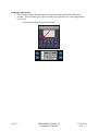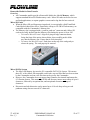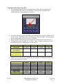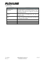
1
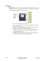
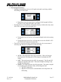
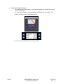
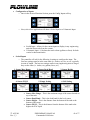
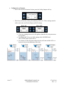
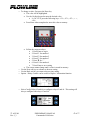
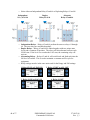
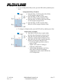
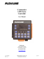
Commander LI90 Series Controller User Manual Flowline Inc. 10500 Humbolt Street Los Alamitos, CA 90720 Tel: (562) 598-3015 Fax: (562) 431-8507 www.flowline.com 27 AUG 08 Rev 1_3 PRELIMINARY MANUAL Commander LI90 Series 1 of 57 2 of 57 PRELIMINARY MANUAL Commander LI90 Series 27 AUG 08 Rev 1_3 Preface This manual explains how to use the Commander LI90 series controller. Warranty, Service & Repair To register your product with the manufacturer, go to the Flowline website for on-line registration. The website address is as follows: www.flowline.com On-line Warranty Registration can be found under Contact Us in the Navigation Bar along the side of the home page. If for some reason your product must be returned for factory service, go to the Flowline website to receive a Material Return Authorization number (MRA), providing the following information: 1. Part Number, Serial Number 2. Name and telephone number of someone who can answer technical questions related to the product and its application. 3. Return Shipping Address 4. Brief Description of the Symptom 5. Brief Description of the Application On-line Material Return Authorization can be found under Contact Us in the Navigation Bar along the side of the home page. Click on Return Authorization to begin the MRA request. Once you have received a M RA number, ship the product prepaid in its original packing to: Flowline Factory Service MRA_____ 10500 Humbolt Street Los Alamitos, CA 90720 To avoid delays in processing your repair, write the MRA on the shipping label. Please include the information about the malfunction with your product. This information enables our service technicians to process your repair order as quickly as possible. 27 AUG 08 Rev 1_3 PRELIMINARY MANUAL Commander LI90 Series 3 of 57 Warranty Flowline warrants to the original purchaser of its products that such products will be free from defects in material and workmanship under normal use and service for a period which is equal to the shorter of one year from the date of purchase of such products or two years from the date of manufacture of such products. This warranty covers only those components of the products which hare non-moving and not subject to normal wear. Moreover, products which are modified or altered, and electrical cables which are cut to length during installation are not covered by this warranty. Flowline’s obligation under this warranty is solely and exclusively limited to the repair or replacement, at Flowline’s option, of the products (or components thereof) which Flowline’s examination proves to its satisfaction to be defective. FLOWLINE SHALL HAVE NO OBLIGATION FOR CONSEQUENTIAL DAMAGES TO PERSONAL OR REAL PROPERTY, OR FOR INJURY TO ANY PERSON. This warranty does not apply to products which have been subject to electrical or chemical damage due to improper use, accident, negligence, abuse or misuse. Abuse shall be assumed when indicated by electrical damage to relays, reed switches or other components. The warranty does not apply to products which are damaged during shipment back to Flowline’s factory or designated service center or are returned without the original casing on the products. Moreover, this warranty becomes immediately null and void if anyone other than service personnel authorized by Flowline attempts to repair the defective products. Products which are thought to be defective must be shipped prepaid and insured to Flowline’s factory or a designated service center (the identity and address of which will be provided upon request) within 30 days of the discovery of the defect. Such defective products must be accompanied by proof of the date of purchase. Flowline further reserves the right to unilaterally waive this warranty and to dispose of any product returned to Flowline where: a. There is evidence of a potentially hazardous material present with product. b. The product has remained unclaimed at Flowline for longer than 30 days after dutifully requesting disposition of the product. THERE ARE NO WARRANTIES WHICH EXTEND BEYONDTHE DESCRIPTION ON THE FACE OF THIS WARRANTY. This warranty and the obligations and liabilities of Flowline under it are exclusive and instead of, and the original purchaser hereby waives, all other remedies, warranties, guarantees or liabilities, express or implied. EXCLUDED FROM THIS WARRANTY IS THE IMPLIED WARRANTY OF FITNESS OF THE PRODUCTS FOR A PARTICULAR PURPOSE OR USE AND THE IMPLIED WARRANTY OF MERCHANTABILITY OF THE PRODUCTS. This warranty may not be extended, altered or varied except by a written instrument signed by a duly-authorized officer of Flowline, Inc. 4 of 57 PRELIMINARY MANUAL Commander LI90 Series 27 AUG 08 Rev 1_3 Table of Contents Safety Warnings and Guidelines ..........................................................................................6 Introduction ..........................................................................................................................7 Installation............................................................................................................................9 Panel Mounting ........................................................................................................9 DIN Rail Mounting ................................................................................................10 Dimensions ........................................................................................................................11 Electrical ............................................................................................................................12 Wiring ................................................................................................................................13 Configuration .....................................................................................................................14 Specifications .....................................................................................................................15 Startup ................................................................................................................................16 Common Information.........................................................................................................19 Analog (Scaled Input) ............................................................................................19 Analog (Fixed Input)..............................................................................................20 Application #1 ....................................................................................................................21 Overview ................................................................................................................21 General (Open Functions) ......................................................................................22 General (Secured Functions)..................................................................................24 Configuration of Inputs ..............................................................................25 Configuration of Outputs ...........................................................................27 Application #2 ....................................................................................................................29 Overview ................................................................................................................29 General (Open Functions) ......................................................................................30 General (Secured Functions)..................................................................................32 Configuration of Inputs ..............................................................................33 Configuration of Outputs ...........................................................................35 Application #3 ....................................................................................................................38 Overview ................................................................................................................38 General (Open Functions) ......................................................................................39 General (Secured Functions)..................................................................................40 Configuration of Inputs ..............................................................................41 Volume ...........................................................................................43 Configuration of Outputs ...........................................................................46 Appendix ............................................................................................................................51 Simulation mode ....................................................................................................51 Factory Reset .........................................................................................................53 Changing Applications...........................................................................................54 Removable Media for Data Transfer .....................................................................55 Micro SD Cards .........................................................................................55 Micro SD File System................................................................................55 Using Removable Media to Log Data .......................................................56 27 AUG 08 Rev 1_3 PRELIMINARY MANUAL Commander LI90 Series 5 of 57 Safety Warnings and Guidelines When found on the product, the following symbols specify: Warning: Consult user documentation. Warning: Electrical Shock Hazard. WARNING: To avoid the risk of electric shock or burns, always connect the safety (or earth) ground before making any other connections. WARNING: To reduce the risk of fire, electrical shock, or physical injury it is strongly recommended to fuse the voltage measurement inputs. Be sure to locate fuses as close to the source as possible. WARNING: Replace fuse with the same type and rating to provide protection against risk of fire and shock hazards. WARNING: In the event of repeated failure, do not replace the fuse again as a repeated failure indicates a defective condition that will not clear by replacing the fuse. WARNING: Only qualified electrical personnel familiar with the construction and operation of this equipment and the hazards involved should install, adjust, operate, or service this equipment. Read and understand this manual and other applicable manuals in their entirety before proceeding. Failure to observe this precaution could result in severe bodily injury or loss of life. • • All applicable codes and standards need to be followed in the installation of this product. For I/O wiring (discrete), use the following wire type or equivalent: Belden 9918, 18 AWG or larger. Adhere to the following safety precautions whenever any type of connection is made to the module. • Connect the green safety (earth) ground first before making any other connections. • When connecting to electric circuits or pulse-initiating equipment, open their related breakers. Do not make connections to live power lines. • Make connections to the module first; then connect to the circuit to be monitored. • Route power wires in a safe manner in accordance with good practice and local codes. • Wear proper personal protective equipment including safety glasses and insulated gloves when making connections to power circuits. • Ensure hands, shoes, and floors are dry before making any connection to a power line. • Make sure the unit is turned OFF before making connection to terminals. Make sure all circuits are de-energized before making connections. • Before each use, inspect all cables for breaks or cracks in the insulation. Replace immediately if defective. 6 of 57 PRELIMINARY MANUAL Commander LI90 Series 27 AUG 08 Rev 1_3 Introduction The Commander Series has three unique application configurations. The choice of application is field selectable. The three configurations are: • Multi-Tank Display (Application #1) – Commander will accept up to Four 4-20 mA input transmitters and will provide a 3A SPST relay output for each input. • Differential Level Controller (Application #2) – Commander will monitor the levels above and below a rake and control a relay based upon the defined differential between the two levels. In addition, a differential alarm can be programmed as well as individual alarms for each input. 27 AUG 08 Rev 1_3 PRELIMINARY MANUAL Commander LI90 Series 7 of 57 • 8 of 57 Pump Controller (Application #3) – Commander will accept a single 4-20 mA input transmitter and will provide up to Six 3A SPST relay outputs. PRELIMINARY MANUAL Commander LI90 Series 27 AUG 08 Rev 1_3 Installation • Overview o The mechanical installation greatly affects the operation, safety and appearance of the system. Information is provided to mechanically install the unit such as cut out sizes, mounting procedures and other recommendations for the proper mechanical installation of the unit. • Components o Commander Series display o Terminal Strips Power (3-pin black) Inputs (15-pin Orange) Outputs (15-Pin Black) Optional Interface (5-pin Orange) o Mounting Clips (set of four) Quick Start Guide • Mounting requirements o Commander series can be mounted through a panel or on a DIN rail. • Panel Mounting o Once the panel design has been completed using the criteria and suggestions in the following sections, use the following steps to panel mount the LI90 series. Remove all connectors from the unit. Press the DIN rail clip up to make passing the unit through the cutout easier. Make sure the gasket is installed on the LI90 series and is free from dust and debris. Check that the corners of the gasket are secure. Pass the unit through the panel. Insert the each of the four (4) mounting clips into the slots in the Commander’s case. One clip should be installed on each corner. Lightly tighten each screw so the clip is held in place. Tighten the screws on the clips such that the gasket is compressed against the panel. o For panel mount, use the standard cutout for a ¼ DIN [3.622” (92 mm) x 3.622” (92 mm)]. Use the four mounting clips to secure the display to the panel. A mounting clip will attach to all four sides of the display. Not to Scale 27 AUG 08 Rev 1_3 PRELIMINARY MANUAL Commander LI90 Series 9 of 57 • DIN Rail Mounting o The LI90 series is designed to clip onto standard 35 millimeter DIN rail. If your installation requires liquid or dust protection, make sure the controller is placed in an appropriate sealed panel when mounting on DIN rail. Use the following steps to mount on DIN rail. Move the DIN rail clip to the lower position. Clip the “Top Clips” on the top of the DIN rail. Press the unit into place and press the DIN rail clip up. A small flat-head screwdriver can be used in the slot of the DIN rail clip if clearance is an issue. o Note: The DIN rail connection does not provide an earth ground. o For DIN rail, use a 35 mm DIN Rail. Move the DIN rail clip to the lower position. Clip the “Top Clips” on the top of the DIN rail. Press the unit into place and press the DIN rail clip up. A small flat-head screwdriver can be used in the slot of the DIN rail clip if clearance is an issue. 10 of 57 PRELIMINARY MANUAL Commander LI90 Series 27 AUG 08 Rev 1_3 • Dimensions Front View • • • • Side View Temperature / Ventilation o Ensure that the panel layout design allows for adequate ventilation and maintains the specified ambient temperature range. Consider the impact on the design of the panel layout if operating at the extreme ends of the ambient temperature range. For example, if it is determined that a cooling device is required, allow adequate space and clearances for the device in the panel box or on the panel door. Orientation o When panel-mounted, there are no orientation restrictions on the LI90 series. Noise o Consider the impact on the panel layout design and clearance requirements if noise suppression devices are needed. Be sure to maintain an adequate distance between the controller and noisy devices such as relays, motor starters, etc. Shock and Vibration o The LI90 series has been designed to operate in typical industrial environments that may inflict some shock and vibration on the unit. For applications that may inflict excessive shock and vibration please use proper dampening techniques or relocate the Commander to a location that minimizes shock and/or vibration. 27 AUG 08 Rev 1_3 PRELIMINARY MANUAL Commander LI90 Series 11 of 57 Electrical • Grounding Definition o Ground: The term Ground is defined as a conductive connection between a circuit or piece of equipment and the earth. Grounds are fundamentally used to protect an application from harmful interference causing either physical damage such as by lightning or voltage transients or from circuit disruption often caused by radio frequency interference (RFI). • Ground Specifications o Ideally, a ground resistance measurement from equipment to earth ground is 0 ohms. In reality it typically is higher. The U.S. National Electrical Code (NEC) states the resistance to ground shall not exceed 25 ohms. Flowline recommends less than 15 ohms resistance from our equipment to ground. Resistance greater than 25 ohms can cause undesirable or harmful interference to the device. • How to Test for Good Ground o In order to test ground resistance, a Ground Resistance Tester must be used. A typical Ground Resistance Meter Kit contains a meter, two or three wire leads, and two ground rods. Instructions are supplied for either a two-point or threepoint ground test. Below shows a two-point ground connection test. 12 of 57 PRELIMINARY MANUAL Commander LI90 Series 27 AUG 08 Rev 1_3 • Wiring o Power • Connect to Earth Ground. Apply 10 - 30 VDC. o Inputs • Commander can connect up to four 4-20 mA inputs. 27 AUG 08 Rev 1_3 PRELIMINARY MANUAL Commander LI90 Series 13 of 57 o Outputs • Commander can connect up to 6 relays, depending on the application selection. • Relays can switch voltages up to 275 VAC, 30 VDC with a maximum output current of 3 A at 250 VAC, resistive. Configuration • Commander Series is configured via the Human Machine Interface (HMI) located on the front cover of the controller 14 of 57 PRELIMINARY MANUAL Commander LI90 Series 27 AUG 08 Rev 1_3 Specifications Display Graphics/Text: Pixels: Display Technology: Keypad Touch screen Total Keys: Function Keys: Controller Memory: Logic Scan Rate: Memory Card Slot: General Specs Height: Width: Depth: Weight: Environmental: Wash down: Max. panel thickness: Cut-out: Required Power Steady State: Inrush: Primary Power Range: Relative Humidity: Clock Accuracy: Operating Temp.: Terminal Type: Certifications: Analog Inputs Number of Channels: Input Ranges: Max. Over-Current: Relay Outputs Outputs per Module: Commons per Module: Max. Output Current: Max. Output Voltage: Max. Switched Power: Expected Life No load: Rated load: Max. Switching Rate: Type: Response Time: 27 AUG 08 Rev 1_3 Yes / Yes 128 x 64 Backlit LCD 20 10 256 KB 1.2 mS/K Up to 1 GB 3.7” (95.1 mm) 3.7” (95.1 mm) 2.5” (63.9 mm) 12.5 oz (0.354 kg) 0 to 50 °C NEMA 4X 5 mm 3.622” (92 mm) x 3.622” (92 mm) 130 mA @ 24 VDC 30 A for 1 ms @ 24 VDC 10 – 30 VDC 5 to 95% Non-condensing +/- One Minute/Month at 20C 0°C to +50°C Screw Type, 5 mm Removable CE UL 4 4 – 20 mA 35 mA 6 relay 6 3 A at 250 VAC, resistive 275 VAC, 30 VDC 1250 VA, 150 W 5,000,000 100,000 300 CPM at no load / 20 CPM at rated load Mechanical Contact One update per ladder scan plus 10 ms PRELIMINARY MANUAL Commander LI90 Series 15 of 57 Startup • When the Commander is powered for the first time, the LI90 series will allow the end user to select the application to be used. Follow the instructions on the screen to choose the application. o Application #1 / Multi-Tank Display (Press F2) – Commander will accept up to Four 4-20 mA input transmitters and will provide a 3A SPST relay output for each input. 16 of 57 PRELIMINARY MANUAL Commander LI90 Series 27 AUG 08 Rev 1_3 o Application #2 / Differential Level Controller (Press F3) – Commander will monitor the levels above and below a rake and control a relay based upon the defined differential between the two levels. In addition, a differential alarm can be programmed as well as individual alarms for each input. o Application #3 / Pump Controller (Press F4) – Commander will accept a single 4-20 mA input transmitter and will provide up to Six 3A SPST relay outputs. 27 AUG 08 Rev 1_3 PRELIMINARY MANUAL Commander LI90 Series 17 of 57 • If you need to change the application selection, press and hold the ESC button for 5 seconds. This will return you to the Selection Screen and allow for a new application to be selected. o The selection can be accessed at any time. 18 of 57 PRELIMINARY MANUAL Commander LI90 Series 27 AUG 08 Rev 1_3 Common Information – There are several configuration aspects that are similar for all three applications in the LI90 series. • Analog Input o The Commander accepts any 4-20 mA signal. o The Commander has the ability to accept a 4-20 mA that has been scaled to the size of the tank / vessel or with a 4-20 mA that is from a non-configured transmitter (in its original factory setup). o There are six parameters required to configure an analog input in the LI90 series. o For a scaled output. Use this description when using a transmitter that has been configured with 4 mA set to an empty tank/vessel and 20 mA set to a full tank/vessel. • • • • • • 27 AUG 08 Rev 1_3 Sensor Max. Range – This is the distance from the bottom of the tank to the bottom of the installed sensor. Sensor Dead Band – This is the distance from the full level of liquid to the bottom of the sensor. Sensor Height – This is the distance from the bottom of the tank to the bottom of the installed sensor. This will be the same setting as the Sensor Max. Range. Sensor Fill_H – This is the distance from the bottom of the tank to the highest level of liquid. Adding the Fill_H value to the Dead Band value will equal the Max. Range or Height values. Empty Setting – This is the display value when the tank is empty. Full Setting – This is the display value when the tank is full. PRELIMINARY MANUAL Commander LI90 Series 19 of 57 o For a non-scaled output. Use this description when using a transmitter that is either set with its original Factory Settings or with a transmitter that has a fixed (non-configurable) 4-20 mA output: • • • • • • 20 of 57 Sensor Max. Range – This is the maximum range of the sensor. This is typically the 4 mA set point for the sensor. Use the sensor’s manual to obtain the sensors maximum range (4 mA output). Sensor Dead Band – This is the dead band for the level sensor. Use the sensor’s manual to obtain the sensors dead band (20 mA output). Sensor Height – This is the distance from the bottom of the tank to the bottom of the installed sensor Sensor Fill_H – This is the distance from the bottom of the tank to the highest level of liquid Empty Setting – This is the display value when the tank is empty. Full Setting – This is the display value when the tank is full. PRELIMINARY MANUAL Commander LI90 Series 27 AUG 08 Rev 1_3 Application #1 • Overview o Multi-Tank Display – The LI90 series in this application is typically used to eliminate the need of one display for each transmitter. This application can accept up to Four 4-20 mA input transmitters and will provide a 3A SPST relay output for each input. • • • • 27 AUG 08 Rev 1_3 Power: Operate from 12 to 24 VDC power Inputs: Accept up to four 4-20 mA inputs, the inputs will be powered by 12 to 24 VDC power source Outputs: Each input channel has a relay assigned (4 relays total) Mounting: Commander can be ¼ DIN mounted and DIN rail mountable PRELIMINARY MANUAL Commander LI90 Series 21 of 57 • General (Open Functions) o Opening Screen indicates the Level of Liquid in the tank/vessel along with the true analog (4-20 mA) input for channel #1 and the status of Relay #1 • Regardless on how the input level is configured, the bar graph will show the true 4-20 mA input provided by the sensor o Pressing the Lower Right Soft key will jump the display to a screen showing the same information for Channel #2. o Pressing the lower Right soft key will continue to Channels #3 and #4 and then the Relay Status Page • Sequence is as follows: • Channel 1, Channel 2, Channel 3, Channel 4, Relay Info, Channel 1, … Channel 1 Channel 2 Channel 4 Channel 3 Hand/Off/Auto (HOA) o In the Relay Info screen, pressing the upper left soft key will jump the screen to the HAND / OFF / AUTO (H.O.A.) functions for each relay. 22 of 57 PRELIMINARY MANUAL Commander LI90 Series 27 AUG 08 Rev 1_3 • • The H.O.A. screen for each relay will indicate each relay, the current status of each relay and soft keys to jump back or to the next relay. The first time the LI90 series is powered up, all of the relays will be in the OFF mode. To activate the relay, you will need to change the relay mode to AUTO. • • • 27 AUG 08 Rev 1_3 AUTO – This mode places the relay in automatic. Relay will energize based upon the ON setting and will De-energize based upon the OFF setting. OFF – This mode turns the relay OFF (de-energized). The ON and OFF settings are ignored in this mode. This mode is helpful in taking a relay off-line for maintenance. HAND – This mode turns the relay ON (energized). This mode is helpful in overriding a relay function. Relay will be energized until o The OFF is selected or o When the AUTO mode is selected and the level drops below the OFF setting PRELIMINARY MANUAL Commander LI90 Series 23 of 57 • General (Secured Functions) o The configuration of the display/input and relays/output are all under the secured section of the display. o To access these functions, press and hold the ENTER key for 5 seconds. The display will jump to the configuration section. o To leave the Secured Function section, press Exit 24 of 57 PRELIMINARY MANUAL Commander LI90 Series 27 AUG 08 Rev 1_3 • Configuration of Inputs o Once in the Secured Function Section, press the Config Inputs soft key o Press the Next or Back soft keys to scroll to the input you would like to configure. o Upon selecting an input channel, the controller will ask for the following 6 settings to configure the input. The first four settings must be in the same units (i.e. inches, cm, feet, m, etc.) typically in units of length. The last two settings can be in any engineering units as long as they are the same (i.e. inches, cm, gallons, liters, etc.) 1. Sensor Max. Range 2. Sensor Dead Band 3. Sensor Height 4. Sensor Fill_H 5. Empty Setting 6. Full Setting 1. Sensor Max. Range –This is the distance from the bottom of the tank to the bottom of the installed sensor with a scaled 4-20 mA output. For a fixed output, this is the maximum range of the sensor. Use the sensor’s manual to obtain the sensors maximum range (4 mA output) 2. Sensor Dead Band – This is the distance from the full level of liquid to the bottom of the sensor with a scaled 4-20 mA output. For a fixed output, this is the dead band for the level sensor. Use the sensor’s manual to obtain the sensors dead band (20 mA output). 3. Sensor Height – This is the distance from the bottom of the tank to the bottom of the installed sensor. 4. Sensor Fill_H – This is the distance from the bottom of the tank to the highest level of liquid. 5. Empty Setting – This is the display value when the tank is empty. 6. Full Setting – This is the display value when the tank is full. • Use the Next soft key to advance to the next setting. • Use the Back soft key to return to the previous setting. 27 AUG 08 Rev 1_3 PRELIMINARY MANUAL Commander LI90 Series 25 of 57 Scaled 4-20 mA Output Fixed 4-20 mA Output o To change a value, first press the Enter key • The value will be highlighted • Use the 10-digit keypad to enter the desired value • I.e. for 123.4, press the following keys: <F1>, <F2>, <F3>, <▼>, <F4>, • Press Enter when completed to store this value to memory • • 26 of 57 Follow the sequence above: • 1. Press Enter to begin • 2. Press F1 for number 1 • 3. Press F2 for number 2 • 4. Press F3 for number 3 • 5. Press ▼ for “.” • 6. Press F4 for number 4 • 7. Press Enter to save setting The screen cannot change until a value is stored in memory. PRELIMINARY MANUAL Commander LI90 Series 27 AUG 08 Rev 1_3 • Configuration of Outputs o Once in the Secured Function Section, press the Config Outputs soft key o Each relay will ask for a Relay ON and Relay OFF level. These settings must be in the same units used for the Empty and Full settings Relay ON • • • High Alarm Relay OFF If you are reading between 0 to 500 gallons, then the relay set points must be in gallons For Pumps and Valves, use both settings as the ON/OPEN and OFF/CLOSE points for the device For Alarms, use the ON point where the relay will start and the OFF as a hysteresis to prevent chattering of the relay Low Alarm Automatic Fill Automatic Empty o To change a value, first press the Enter key • The value will be highlighted • Use the 10-digit keypad to enter the desired value • I.e. for 123.4, press the following keys: <F1>, <F2>,<F3>,<.>,<F4>, • Press Enter when completed to store this value to memory 27 AUG 08 Rev 1_3 PRELIMINARY MANUAL Commander LI90 Series 27 of 57 • Follow the sequence above: • 1. Press Enter to begin • 2. Press F1 for number 1 • 3. Press F2 for number 2 • 4. Press F3 for number 3 • 5. Press ▼ for “.” • 6. Press F4 for number 4 • 7. Press Enter to save setting • The screen cannot change until a value is stored in memory. o Use the Next soft key to advance to the next setting o Use the Back soft key to return to the previous setting o When done, press Exit to leave the Secured Function Section 28 of 57 PRELIMINARY MANUAL Commander LI90 Series 27 AUG 08 Rev 1_3 Application #2 • Overview o Differential Level Controller – Commander will monitor the levels above and below a rake and control a relay based upon the defined differential between the two levels. In addition, a differential alarm can be programmed as well as individual alarms for each input. • • • • 27 AUG 08 Rev 1_3 Power: Operate from 12 to 24 VDC power Inputs: Accept up to two 4-20 mA inputs, the inputs will be powered by 12 to 24 VDC power source Outputs: Two alarm relays (one for each channel) and two relays that activate based upon the differential value between the two inputs. Mounting: Commander can be ¼ DIN mounted and DIN rail mountable PRELIMINARY MANUAL Commander LI90 Series 29 of 57 • General (Open Functions) o Opening Screen indicates the Level of Liquid in the tank/vessel along with the true analog (4-20 mA) input for both input channel#1 and #2 • Regardless on how the input level is configured, the bar graph will show the true 4-20 mA input provided by the sensor o Pressing the Lower Right Soft Key will jump the display to show the following: • Channel 1 and 2, Channel 1 only, Channel 2 only, Relay Info… Channel 1 & 2 Channel 2 only 30 of 57 Channel 1 only Relay info PRELIMINARY MANUAL Commander LI90 Series 27 AUG 08 Rev 1_3 o In the Relay Info screen, pressing the upper right soft key will jump the screen to the HAND / OFF / AUTO (H.O.A.) functions for each relay. • The H.O.A. screen for each relay will indicate each relay, the current status of each relay and soft keys to jump back or to the next relay • AUTO – This mode places the relay in automatic. Relay will energize based upon the ON setting and will De-energize based upon the OFF setting. • OFF – This mode turns the relay OFF (de-energized). The ON and OFF settings are ignored in this mode. This mode is helpful in taking a relay off-line for maintenance. • HAND – This mode turns the relay ON (energized). This mode is helpful in overriding a relay function. Relay will be energized until o The OFF is selected or o When the AUTO mode is selected and the level drops below the OFF setting o Pressing the lower right soft key (Next) will return the controller to the opening screen 27 AUG 08 Rev 1_3 PRELIMINARY MANUAL Commander LI90 Series 31 of 57 • General (Secured Functions) o The configuration of the display/inputs and relays/outputs are all under the secured section of the display o To access these functions, press and hold the ENTER key for 5 seconds. The display will jump to the configuration section. o To leave the Secured Function section, press Exit 32 of 57 PRELIMINARY MANUAL Commander LI90 Series 27 AUG 08 Rev 1_3 • Configuration of Inputs o Once in the Secured Function Section, press the Config Inputs soft key o Press the Next or back soft keys to scroll to the input you would like to configure. o Upon selecting an input channel, the controller will ask for the following 6 settings to configure the input. The first four settings must be in the same units (i.e. inches, cm, feet, m, etc.) typically in units of length. The last two settings can be in any engineering units as long as they are the same (i.e. inches, cm, gallons, liters, etc.) 1. Sensor Max. Range 2. Sensor Dead Band 3. Sensor Height 4. Sensor Fill_H 5. Empty Setting 6. Full Setting 1. Sensor Max. Range –This is the distance from the bottom of the tank to the bottom of the installed sensor with a scaled 4-20 mA output. For a fixed output, this is the maximum range of the sensor. Use the sensor’s manual to obtain the sensors maximum range (4 mA output) 2. Sensor Dead Band – This is the distance from the full level of liquid to the bottom of the sensor with a scaled 4-20 mA output. For a fixed output, this is the dead band for the level sensor. Use the sensor’s manual to obtain the sensors dead band (20 mA output). 3. Sensor Height – This is the distance from the bottom of the tank to the bottom of the installed sensor. 4. Sensor Fill_H – This is the distance from the bottom of the tank to the highest level of liquid. 5. Empty Setting – This is the display value when the tank is empty. 6. Full Setting – This is the display value when the tank is full. • Use the Next soft key to advance to the next setting. • Use the Back soft key to return to the previous setting. 27 AUG 08 Rev 1_3 PRELIMINARY MANUAL Commander LI90 Series 33 of 57 Scaled 4-20 mA Output Fixed 4-20 mA Output o To change a value, first press the Enter key • The value will be highlighted • Use the 10-digit keypad to enter the desired value • I.e. for 123.4, press the following keys: <F1>, <F2>, <F3>, <. >, <F4>, • Press Enter when completed to store this value to memory • • 34 of 57 Follow the sequence above: • 1. Press Enter to begin • 2. Press F1 for number 1 • 3. Press F2 for number 2 • 4. Press F3 for number 3 • 5. Press ▼ for “.” • 6. Press F4 for number 4 • 7. Press Enter to save setting The screen cannot change until a value is stored in memory. PRELIMINARY MANUAL Commander LI90 Series 27 AUG 08 Rev 1_3 • Configuration of Outputs o Once in the Secured Function Section, press the Config Outputs soft key • Relays #1 and #2 will ask for a Relay ON and Relay OFF level. These settings must be in the same units used for the Empty and Full settings Relay ON • • • High Alarm 27 AUG 08 Rev 1_3 Relay OFF If you are reading between 0 to 500 gallons, then the relay set points must be in gallons For Pumps and Valves, use both settings as the ON/OPEN and OFF/CLOSE points for the device For Alarms, use the ON point where the relay will start and the OFF as a hysteresis to prevent chattering of the relay Low Alarm Automatic Fill PRELIMINARY MANUAL Commander LI90 Series Automatic Empty 35 of 57 • To change a value, first press the Enter key • The value will be highlighted • Use the 10-digit keypad to enter the desired value o I.e. for 123.4, press the following keys: <F1>, <F2>, <F3>, <.>, <F4>, • Press Enter when completed to store this value to memory • • 36 of 57 Follow the sequence above: • 1. Press Enter to begin • 2. Press F1 for number 1 • 3. Press F2 for number 2 • 4. Press F3 for number 3 • 5. Press ▼ for “.” • 6. Press F4 for number 4 • 7. Press Enter to save setting The screen cannot change until a value is stored in memory. PRELIMINARY MANUAL Commander LI90 Series 27 AUG 08 Rev 1_3 • Relays #3 and #4 will ask for a Differential ON and Differential OFF level. These settings must be in the same units used for the Empty and Full settings. Differential ON Differential OFF • • • • 27 AUG 08 Rev 1_3 This allows the end use to select a differential level between the two analog inputs • Channel #1 must be the upstream level and Channel #2 the downstream level • Typically, Relay #3 is used for the main differential control and Relay #4 is for an alarm differential Use the Next soft key to advance to the next setting Use the Back soft key to return to the previous setting When done, press Exit to leave the Secured Function Section PRELIMINARY MANUAL Commander LI90 Series 37 of 57 Application #3 • Overview o Pump Controller – The LI90 series in this application is typically used to provide multiple relay contacts for a single 4-20 mA input. Relays 5 and 6 can be combined to be programmed as duplexing / alternating relays. • • • • • • • 38 of 57 Power: Operates from 12 to 24 VDC power Inputs: Accepts a single 4-20 mA input, the input will be powered by 12 to 24 VDC power source Outputs: 6 relays are available to program as alarms, pumps or valves Enclosure: Front panel must be NEMA 4X rated Mounting: Panel must be ¼ DIN mounted and DIN rail mountable Volumetric: Display can indicate level in either Gallons or Liters for vertical and horizontal tanks Simulation mode: Use this mode to simulate the level of liquid and test relay operation without changing the true liquid level PRELIMINARY MANUAL Commander LI90 Series 27 AUG 08 Rev 1_3 • General (Open Functions) o Opening Screen indicates the Level of Liquid in the tank/vessel along with the true analog (4-20 mA) input • Regardless on how the input level is configured, the bar graph will show the true 4-20 mA input provided by the sensor o Pressing the Lower Left Soft key will jump the display to indicate the relay status. Above the relay status will be the liquid level. • Pressing the lower left soft key will return the display back to the opening screen • Pressing the upper left soft key will jump the screen to the HAND / OFF / AUTO (H.O.A.) functions for each relay. o The H.O.A. screen for each relay will indicate each relay, the current status of each relay and soft keys to jump back or to the next relay • • • 27 AUG 08 Rev 1_3 AUTO – This mode places the relay in automatic. Relay will energize based upon the ON setting and will De-energize based upon the OFF setting. OFF – This mode turns the relay OFF (de-energized). The ON and OFF settings are ignored in this mode. This mode is helpful in taking a relay off-line for maintenance. HAND – This mode turns the relay ON (energized). This mode is helpful in overriding a relay function. Relay will be energized until • The OFF is selected or • When the AUTO mode is selected and the level drops below the OFF setting PRELIMINARY MANUAL Commander LI90 Series 39 of 57 • General (Secured Functions) o The configuration of the display, relays and simulations are all under the secured section of the display o To access these functions, press and hold the ENTER key for 5 seconds. The display will jump to the configuration section. o To leave the Secured Function section, press Exit 40 of 57 PRELIMINARY MANUAL Commander LI90 Series 27 AUG 08 Rev 1_3 • Configuration of Inputs o Once in the Secured Function Section, press the Config Inputs soft key o Next, select if the application will show a Scaled Input or a Volumetric Input • • • Scaled Input – Allows for the current inputs to display in any engineering units the linear scale from the current Volumetric Input – Calculates the total volume (gallons or liters) for both vertical or horizontal tanks Scaled Inputs o The controller will ask for the following 6 settings to configure the input. The first four settings must be in the same units (i.e. inches, cm, feet, m, etc.) typically in units of length. The last two settings can be in any engineering units as long as they are the same (i.e. inches, cm, gallons, liters, etc.) 1. Sensor Max. Range 4. Sensor Fill_H • • • • 27 AUG 08 Rev 1_3 2. Sensor Dead Band 3. Sensor Height 5. Empty Setting 6. Full Setting Sensor Max. Range – This is the maximum range of the sensor located on top of the tank. Sensor Dead Band – This is the dead band for the level sensor Sensor Height – This is the distance from the bottom of the tank to the bottom of the sensor Sensor Fill_H – This is the distance from the bottom of the tank to the highest level of liquid PRELIMINARY MANUAL Commander LI90 Series 41 of 57 • • • • Empty Setting – This is the display value when the tank is empty Full Setting – This is the display value when the tank is full Use the Next soft key to advance to the next setting Use the Back soft key to return to the previous setting Scaled 4-20 mA Output Fixed 4-20 mA Output o To change a value, first press the Enter key • The value will be highlighted • Use the 10-digit keypad to enter the desired value • I.e. for 123.4, press the following keys: <F1>, <F2>, <F3>, <. >, <F4>, • Press Enter when completed to store this value to memory. • • 42 of 57 Follow the sequence above: • 1. Press Enter to begin • 2. Press F1 for number 1 • 3. Press F2 for number 2 • 4. Press F3 for number 3 • 5. Press ▼ for “.” • 6. Press F4 for number 4 • 7. Press Enter to save setting The screen cannot change until a value is stored in memory. PRELIMINARY MANUAL Commander LI90 Series 27 AUG 08 Rev 1_3 • Volumetric Inputs o The controller will ask basic shape and dimensional information in order to display either the gallons or liters within the tank or vessel. • Dimensional information must be entered as either inches or cm. • Dimensional inches must show gallons and cm must show liters. • Transmitter must be configured such that tank empty is 4 mA and tank full is 20 mA. o Select between either Vertical Tanks or Horizontal Tanks. Vertical Tanks Horizontal Tanks o Choose between Gallons or Liters for the display output. • • 27 AUG 08 Rev 1_3 When choosing Gallons, make sure all dimensional information entered is in inches. When choosing Liters, make sure all dimensional information entered is in cm. PRELIMINARY MANUAL Commander LI90 Series 43 of 57 o Vertical Tanks – Select among Rectangular, Round Bottom or Cone Bottom. Rectangular Cone Bottom 1. Sensor Height 2. Tank Height 3. Tank Width/Diameter 4. Tank Length/Cone • • • • • • 44 of 57 Round Bottom Sensor Height – This is the distance from the bottom of the tank to the bottom of the sensor Tank Height – This is a dimension for either the Height of the Tank or the Height of the Straight Side of the cone bottom tank. Tank Width / Diameter – This is either the width of the tank or the diameter of the tank Tank Length / Cone – This is either the length of the tank or the Height of the Cone. You do not need to configure this setting for the Round Bottom tank. Use the Next soft key to advance to the next setting Use the Back soft key to return to the previous setting PRELIMINARY MANUAL Commander LI90 Series 27 AUG 08 Rev 1_3 o Horizontal Tanks – Select among Flat Ends or Round Ends. Length Diameter Flat Ends • • • • • • 27 AUG 08 Rev 1_3 Round Ends 1. Sensor Height 2. Tank Length 3. Tank Diameter 4. End Cap Length Sensor Height – This is the distance from the bottom of the tank to the bottom of the sensor Tank Length – This is a length of the tank. Tank Diameter – This is diameter of the tank. End Cap Length – This is the distance for one of the end caps. You do not need to configure this setting for the Flat End Tank. Use the Next soft key to advance to the next setting Use the Back soft key to return to the previous setting PRELIMINARY MANUAL Commander LI90 Series 45 of 57 • Configuration of Outputs o Once in the Secured Function Section, press the Config Outputs soft key o Each relay will ask for a Relay ON and Relay OFF level. These settings must be in the same units used for the Empty and Full settings Relay ON • • • High Alarm 46 of 57 Relay OFF If you are reading between 0 to 500 gallons, then the relay set points must be in gallons For Pumps and Valves, use both settings as the ON/OPEN and OFF/CLOSE points for the device For Alarms, use the ON point where the relay will start and the OFF as a hysteresis to prevent chattering of the relay Low Alarm Automatic Fill PRELIMINARY MANUAL Commander LI90 Series Automatic Empty 27 AUG 08 Rev 1_3 o To change a value, first press the Enter key • The value will be highlighted • Use the 10-digit keypad to enter the desired value • I.e. for 123.4, press the following keys: <F1>, <F2>, <F3>, <. >, <F4>, • Press Enter when completed to store this value to memory • Follow the sequence above: • 1. Press Enter to begin • 2. Press F1 for number 1 • 3. Press F2 for number 2 • 4. Press F3 for number 3 • 5. Press ▼ for “.” • 6. Press F4 for number 4 • 7. Press Enter to save setting • The screen cannot change until a value is stored in memory. o Use the Next soft key to advance to the next setting o Use the Back soft key to return to the previous setting o Option – Relays 5 and 6 can be used as a Duplex / Alternation function o Select Config. Relay #5 and #6 to configure relays #5 and #6. This setting will always configure both relays #5 and #6. 27 AUG 08 Rev 1_3 PRELIMINARY MANUAL Commander LI90 Series 47 of 57 o Select either an Independent Relay #5 and #6 or Duplexing Relays #5 and #6. Independent Relay #5 & #6 Duplex Relay #5 & #6 Alternate Relay #5 and #6 o Independent Relays – Relays #5 and #6 perform the same as relays #1 through #4. The two relays are not linked together. o Duplex Relays – Relays #5 and #6 are linked together with two unique start levels and a common off position. The relays will also alternate between each LEAD start. If the level ever reaches the LAG start, the remaining relay will activate. o Alternating Relays – Relays #5 and #6 will switch back and forth each time the ON level is reached. This is used to maintain a common use/life cycle for equipment. o Relay settings must be in the same units used for the Empty and Full settings 48 of 57 1. Relay #5 ON or LEAD ON 2. Relay #5 OFF or ALL OFF 3. Relay #6 ON or LAG ON 4. Relay #6 OFF PRELIMINARY MANUAL Commander LI90 Series 27 AUG 08 Rev 1_3 • To use as Independent Relay mode, press the IND soft key and then press Next. Independent Relays #5 and #6 • Enter the Relay #5 ON set point (where Relay #5will energize) and press Next • Enter the Relay #5 OFF set point (where Relay #5 will de-energize) and press Next • Enter the Relay #6 ON set point (where Relay #6 will energize) and press Next. • Enter the Relay #6 OFF set point (where Relay #6 will de-energize) and press Next. • To change to a Duplex mode, press the DUP soft key and then press Next. Duplex Relays #5 and #6 • Enter the LEAD ON relay set point (where the lead relay will energize) and press Next • Enter the ALL OFF relay set point (where both relays will de-energize) and press Next • Enter the LAG ON relay set point (where the lag relay will energize) and press Next. o You do not need to provide a value for Relay #6 OFF. o Duplex can be used as a Filling or Emptying configuration. o Always make sure that the LAG ON is above the LEAD ON for an Empty configuration or below the LEAD ON for a Fill configuration. 27 AUG 08 Rev 1_3 PRELIMINARY MANUAL Commander LI90 Series 49 of 57 • To change to an Alternation mode, press the DUP soft key and then press Next. Alternate Relays #5 and #6 • Enter the LEAD ON relay set point (where relay #5 will energize) and press Next • Enter the ALL OFF relay set point (where both relays will de-energize) and press Next • Enter the LAG ON relay set point (where relay #6 will energize) and press Next. o You do not need to provide a value for Relay #6 OFF. o Alternate can be used as a Filling or Emptying configuration. o Always make sure that the LAG ON is the same as the LEAD ON. This will enable Relays 5 and #6 to alternate each time a relay is to become energized. • To return Relays 5 and 6 back to an independent mode, press the IND soft key o When done, press Exit to leave the Secured Function Section 50 of 57 PRELIMINARY MANUAL Commander LI90 Series 27 AUG 08 Rev 1_3 Appendix Simulation Mode This mode enables the end user to simulate changes in level without having the level of liquid move. The display will simulate level of liquid and will turn the relays ON and OFF according to how they were configured. For example, if Relay 1 is set as a Pump Empty with an ON setting for 100.0 inches and an OFF setting of 30.0 inches, then when the display goes above 100.0, Relay 1 will energize and when the level falls below 30.0, Relay 1 will de-energize. This function can be used to test the wiring and to verify if the configuration is set accordingly. Please note: Simulation mode will energize and de-energize all configured relays. Any devices wired to the relays will become active during simulation mode. To turn off individual relays, Select OFF in the H.O.A. section before entering the Simulation mode. • Simulation Mode I sunder the secured section of the display o To access this function, press and hold the ENTER key for 5 seconds. The display will jump to the configuration section. o Once in the Secured Function Section, press the Simulation Mode soft key 27 AUG 08 Rev 1_3 PRELIMINARY MANUAL Commander LI90 Series 51 of 57 o Next, press the Begin Simulation soft key to proceed or the Back soft key to return o Next press the YES soft key to begin the Simulation o Simulation mode will begin after a short count down o Once in Simulation mode, use the two soft keys on the left to increase and decrease the level per your requirements o Check all active relays to verify operation o To exit from Simulation mode, press the Exit soft key in the lower right corner of the screen 52 of 57 PRELIMINARY MANUAL Commander LI90 Series 27 AUG 08 Rev 1_3 Factory Reset • At anytime, the Commander Series can be reset to its original factory settings. To do so perform the following: o Press and hold the F10 button for 10 seconds o Release the F10 button when the Factory Reset? Screen appears. o To reset, press the soft key for Yes and press F10 to enter o The LI90 series will be reset to its original setting o Pressing Enter with NO active will return the display back to it current setting and nothing will be reset. 27 AUG 08 Rev 1_3 PRELIMINARY MANUAL Commander LI90 Series 53 of 57 Changing Applications • If you need to change the application selection, press and hold the ESC button for 5 seconds. This will return you to the Selection Screen and allow for a new application to be selected. o The selection can be accessed at any time. 54 of 57 PRELIMINARY MANUAL Commander LI90 Series 27 AUG 08 Rev 1_3 Removable Media for Data Transfer Overview • All Commander models provide a Removable Media slot, labeled Memory, which supports standard Micro SD Flash memory cards. Micro SD cards can be used to save and load applications, to capture graphics screens and to log data for later retrieval. Micro SD Cards • When the Micro SD card format was introduced, it was originally called TransFlash. Cards labeled either Micro SD or TransFlash, with up to 2.0 GB of Flash memory, are compatible with the Commander’s Memory slot. • The Memory slot is equipped with a “push-in, push-out” connector and a Micro SD card can be safely inserted into the Memory slot whether the power is On or Off. o To install a Micro SD card: Align its 8-pin gold edge connector down, facing the front of the unit as shown below; then carefully push it all the way into the Memory slot. Ensure that it clicks into place. o To remove the Micro SD card: Push down on the top of the card gently to release the spring. The card pops up for removal. Installing Removable Memory Card Micro SD File System • The Micro SD Memory slot uses the PC-compatible FAT16 File System. This means that a PC, with a Micro SD-compatible card reader, can read files that have been written by the Commander and can write files that can be read by the Commander. • However, the Commander does not support long filenames, but instead implements the 8.3 filename format. This means that all file and directory names must consist of up to 8 characters, followed by an optional dot, and an optional extension with up to 3 characters. • Directories and sub-directories can be nested up to 16 levels deep as long as each pathname string does not exceed 147 characters. 27 AUG 08 Rev 1_3 PRELIMINARY MANUAL Commander LI90 Series 55 of 57 Using Removable Media to Log Data • The Commander has the feature of logging data to a Micro SD card in the form of comma-delimited files, with a .CSV extension. These files are compatible with standard database and spreadsheet PC programs. • • • To activate the data log in the commander, press and hold the Left Arrow (shown above) for 10 seconds. When Data Log Activated appears, release the button. The unit will log the four analog inputs at rate of once per 15 seconds. When completed, follow the previous instructions for removing the Micro SD card. The data in the card will appear in five folders. Folder A_Inputs contains the raw and scaled data for the four analog inputs (see chart below). Data Folder Raw analog input Channel 1 A_Inputs %AI0001 Channel 2 A_Inputs %AI0002 Channel 3 A_Inputs %AI0003 Channel 4 A_Inputs %AI0004 %R0107 %R0207 %R0307 %R0407 (referenced between 0 to 32,000 units) Scaled input (referenced between Empty and Full settings) • Folders AI1_Set, AI2_Set, AI3_Set and AI4_Set contain the configuration information for the analog inputs (see below). Data Folder Sensor Max. Range Sensor Dead Band Sensor Height Sensor Fill_H Empty Setting Full Setting 56 of 57 Channel 1 AI1_Set %R0123 %R0125 %R0133 %R0135 %R0103 %R0105 Channel 2 AI2_Set %R0223 %R0225 %R0233 %R0235 %R0203 %R0205 PRELIMINARY MANUAL Commander LI90 Series Channel 3 AI3_Set %R0323 %R0325 %R0333 %R0335 %R0303 %R0305 Channel 4 AI4_Set %R0423 %R0425 %R0433 %R0435 %R0403 %R0405 27 AUG 08 Rev 1_3 Troubleshooting PROBLEM No power to the transmitters No power from the relay contacts Relays stays OFF all the time 27 AUG 08 Rev 1_3 SOLUTION The Analog Inputs are not internally powered. Power for transmitters must be provided from an alternative source. Typically, it is the same power supply that is providing power to the LI90-1001. All of the relays are dry contact relays. Power for the device the relays are switching must come from an alternative source. Make sure that the Hand, OFF Auto for the relay is set for Auto. The OFF setting will keep the relay OFF until this setting has been changed. PRELIMINARY MANUAL Commander LI90 Series 57 of 57