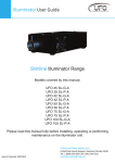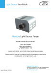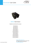
1
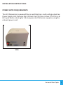
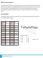
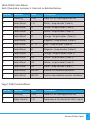
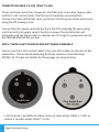
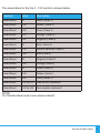
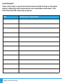
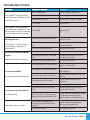
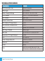
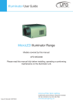
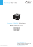
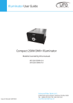
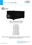
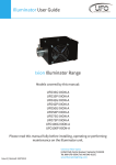
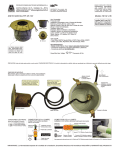
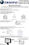
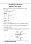
Illuminator User Guide
Vega Decorative Illuminator Range
Models covered by this manual:
UFO VEGA
UFO VEGA - CM
UFO VEGA - TM
UFO VEGA - CDMX
UFO VEGA - TDMX
UFO VEGA - C 0-10V
UFO VEGA - T 0-10V
Please read this manual fully before installing, operating or performing
maintenance on the illuminator unit.
Universal Fiber Optic Lighting LLC
Issue 1 | Revised: 12022014
6119A Clark Center Avenue | Sarasota | FL34238
Tel: 941-343-8115 | Fax:941-296-7906
www.fiberopticlighting.com
INTRODUCTION
Thank you for purchasing this UFO Illuminator.
Please read these instructions fully before connecting your unit to the
electrical supply, and keep them for future reference.
The UFO Vega range of illuminators are suitable for use with either glass or
PMMA fiber-optic harnesses.
The Vega is powered by a 100-240 VAC remote desktop power supply unit.
IMPORTANT
THIS PRODUCT MUST BE INSTALLED IN ACCORDANCE WITH THE
APPLICABLE INSTALLATION CODE BY A PERSON FAMILIAR WITH THE
CONSTRUCTION AND OPERATION OF THE PRODUCT AND THE HAZARDS
INVOLVED.
2
Vega Illuminator Range
INSTALLATION INSTRUCTIONS
POWER SUPPLY REQUIREMENTS
The LED Illuminator is powered from a multifunction, multi-voltage, desk top
Power Supply Unit. Remove the 24V Desk Top PSU from its box. This PSU is an
IEC input device catering for UK, European and USA mains supplies using the
relevant power cord.
VEGA
Universal Fiber Optics
3
CONNECTION – VEGA CM & VEGA TM
There are 2 connections required – the fiber port and the mains supply cable.
The fiber port should be connected first. Connect and secure the fiber optic
connector into the green collar and secure using the M5 locking screw.
Connect the IEC power cord into the Desk Top PSU and plug the mains plug
into the electrical supply socket. Switch on power the led Indicator will
illuminate and the illuminator is ready for use. If no light is produced consult
the TROUBLESHOOTING section.
NOTE: THESE ILLUMINATORS ARE NOT MAINS DIMMABLE
NORMAL OPERATION – VEGA CM & VEGA TM
The VEGA CM (Colorwheel) & VEGA TM (Twinkle Wheel) have manual speed
control on the decorative motor.
Under normal operation the decorative wheel motor speed can be adjusted
manually using the control on the rear of the unit. Motor speed can be
adjusted from STOP to approximately 4 RPM.
To revert to normal manual operation of the wheel, remove top cover to
access the dip switch on the PCB. Set switches 1 to 9 off and switch 10 on.
Replace the cover.
The standard decorative color wheel has 6 glass segments as follows:White (Clear), Yellow, Green, Orange, Magenta, Blue
Alternatively, a 6 segment or 4 segment vari-color wheel can be fitted providing
the following color segment options:FIRE
Canary
Y89
Italian Blue
C45
Golden Amber
G78
G96
Green
Brilliant Blue
Violet
V43
4
Orange
O18
O08
Vega Illuminator Range
B06
Magenta
M56
O59
Jade
Apricot
O14
Turquoise
C47
Bright Blue
Congo
M63
Clear - Outputs white
light
B28
Pink
B93
CONNECTION – VEGA CDMX & VEGA TDMX
There are 3 connections required – the fiber port, the mains supply cable and
the DMX control cable. The fiber port should be connected first. Connect and
secure the fiber optic connector into the green collar and secure using the M5
locking screw.
Connect the IEC power cord into the Desk Top PSU and plug the mains plug
into the electrical supply socket. Switch on power. The LED Indicator will
illuminate and the illuminator is ready for use. If no light is produced consult
the TROUBLESHOOTING section.
To revert to normal manual operation of the wheel, remove top cover to
access the dip switch on the PCB. Set switches 1 to 9 off and switch 10 on.
Replace the cover.
NOTE: THESE ILLUMINATORS ARE NOT MAINS DIMMABLE
For DMX control connect up the DMX control cables to the Mini-XLR sockets
on the rear of the Illuminator. The recommended plug for these sockets is
Multicomp SVP556-TA. The pin out details for the plugs are shown below.
NOTE:
It is recommended that a 120ohm terminating resistor be connected across
DMX+ and DMX- on the last illuminator in the DMX universe or cable run
Universal Fiber Optics
5
REMOTE DMX CONTROL
To set the DMX address, remove the top cover to access the Dip switch on the
PCB. Set the address as detailed below and replace the top cover. Connect up
the Illuminators with the Remote Controller using the Mini XLR sockets
provided on the back of the Illuminator - it doesn’t matter which socket is
used.
DMX ADDRESS
The DMX address of each Illuminator is set manually using the DIP switch on
the PCB as shown below
6
DMX B
Start
Ch#
DIPDMX B
Switches Start
on
Ch#
DIP
Switches
on
1
1
11
1,2,4
2
2
12
3,4
3
1,2
13
1,3,4
4
3
14
2,3,4
5
1,3
15
1,2,3,4
6
2,3
16
5
7
1,2,3
:
8
4
:
9
1,4
:
10
2,4
511
Vega Illuminator Range
Above Example
1 - On
2 - Off
3 - Off
4 - On
5 - Off
1,2,3,4,5
,6,7,8,9
6 - On
7 - On
8 - Off
9 - Off
10 - Off
= Address 105
VEGA CDMX Color Wheel
Each Illuminator occupies 2 channels as detailed below.
Channel
Function
Value
Description
1
Dimming
0-255
From OFF at 0 to Brightest at 255
2
Color Wheel
0-10
White - Snap to color (Color 1)
2
Color Wheel
10
Yellow - Snap to color (Color 2)
2
Color Wheel
20
Green - Snap to color (Color 3)
2
Color Wheel
30
Orange - Snap to color (Color 4)
2
Color Wheel
40
Magenta - Snap to color (Color 5)
2
Color Wheel
50 - 70
Blue - Snap to color (Color 6)
2
Color Wheel
80
Magenta - Snap to color (Color 5)
2
Color Wheel
90
Orange - Snap to color (Color 4)
2
Color Wheel
100
Green - Snap to color (Color 3)
2
Color Wheel
110
Yellow - snap to color (Color 2)
2
Color Wheel
120
White - Snap to color (Color 1)
2
Color Wheel
128-189
Slow to fast rotation clockwise
2
Color Wheel
189-255
Fast to slow rotation counter clockwise
Vega T DMX Twinkle Wheel
Channel
Function
Value
Description
1
Dimming
0-255
From OFF at 0 to Brightest at 255
2
Motor Control
0-10
From stop at 0 to fastest at 255 (3-4rpm)
Universal Fiber Optics
7
CONNECTION VEGA C 0-10V VEGA T 0-10V
There are three connections required - the fiber port, the mains supply cable
and the 0-10V control cable. The fiber port should be connected first.
Connect and secure the fiber optic connector into the green collar and secure
using the M5 locking screw.
Connect the IEC power cord into the Desk Top PSU and plug the mains plug
into the electrical supply socket. Switch on power the led Indicator will
illuminate and the illuminator is ready for use. If no light is produced consult
the TROUBLESHOOTING section.
NOTE: THESE LIGHT SOURCES ARE NOT MAINS DIMMABLE
Connect up the 0-10V control cable to the mini XLR sockets on the rear of the
illuminator. The recommended plug for these sockets is the Multicomp
SVP556-TA. The pin out details for these plugs are shown below.
0-10V Control is available to either control a color wheel (VEGA C 0-10V) or
control a Twinkle wheel (VEGA T 0-10V).
8
Vega Illuminator Range
The value tables for the the 0 - 10V control is shown below:Function
Value
Description
Color Wheel
0V
White (Color 1)
Color Wheel
0.4V
Yellow (Color 2)
Color Wheel
0.8V
Green (Color 3)
Color Wheel
1.2V
Orange (Color 4)
Color Wheel
1.6V
Magenta (Color 5)
Color Wheel
2V
Blue (Color 6)
Color Wheel
2.3V
Returns to White (Color 1)
Color Wheel
2.6V
Blue (Color 6)
Color Wheel
3V
Magenta (Color 5)
Color Wheel
3.6V
Orange (Color 4)
Color Wheel
4V
Green (Color 3)
Color Wheel
4.4V
Yellow (Color 2)
Color Wheel
4.6V
White (Color 1)
Color Wheel
5.4V to 9.2V Slow to fast clockwise*
Color Wheel
9.3V to 10V
Fast counter clockwise*
NOTE:
For Twinkle wheel control use values marked*
Universal Fiber Optics
9
MAINTENANCE
Please Note that a record of all maintenance MUST be kept in the table
below, indicating what maintenance was undertaken and when. This
MUST be dated for warranty purposes.
Date
10 Vega Illuminator Range
Maintenance Undertaken
TROUBLESHOOTING
Problem
Probable Causes
Remedy
Mains supply off
Check supply & reinstate
Unit is dead – no light output
Loose mains plugs
and LED power indicator on PSU
Plug fuse blown (UK)
is not illuminated
Check plugs
Check fuse. If blown, replace
PSU failed
Replace PSU
Unit is dead – no light output
and LED power indicator on PSU
PSU failed
is illuminated, but LED indicator
on Illuminator not illuminated
Replace PSU
For White Light Manual
Dimming Version
Dimming control at minimum
Adjust brightness on dimmer
control at rear
DIP switch no 10 not switched
ON
Remove cover and switch DIP
switch 10 to ON.
LED array or drive failure
Replace illuminator
Motor control at minimum
Adjust motor control at rear
DIP switch No 10 not switched
ON
Remove cover and switch DIP
switch No 10 to ON
Driver circuit or motor failure
Replace Illuminator
DIP switch No 10 is switched ON
Remove cover and switch DIP
switch No 10 to OFF
DMX address not correctly set
Remove cover and set correct
DMX address
No DMX signal from controller
Check DMX controller for correct
setting
Wiring fault on DMX cables
Check cables and repair as
required
Driver circuit failure
Replace Illuminator
DIP switch No 10 is switched
OFF
Remove cover and switch DIP
switch No 10 to ON
No 0-10v signal at illuminator
due to cable or controller fault
Check input to Illuminator using
a DMM set to correct range rectify cable / controller fault
Illuminator dimmed either
manually or by DMX or 0-10v
control
Check and increase dimmer
settings as appropriate
LED driver failure
Replace Illuminator
Unit is dead – no light output
but LED power indicator is
illuminated
For Decorative Manual Motor
Version
Decorative wheel not turning
For Decorative DMX
Not responding to DMX control
For Decorative 0-10v control
Not Responding
Poor light output on fiber
Universal Fiber Optics
11
TECHNICAL SPECIFICATIONS
Description
Details
Port connector size
30mm Diameter
Fiber type
Glass/PMMA
Mains Supply Voltage
100-240V AC, 50-60 Hz.1.8A
PSU Output
24V DC, 2.5A, 60W Maximum
LED Power
Max. 20W
Power Connection
2.1 x 5.5 x 12mm
Min Ambient Temperature
-10ºC
Max Ambient Temperature
+45ºC
Fan
60mm 12V Crossflow
LED Type / Model
White light
LED Life
50,000 hours in ambient 25ºC
Equivalent TH Light Output
120W
CRI
82 (typical)
Color Temperature ºK
3000ºK or 4000ºK
Material
Aluminum
Color
Silver
Size
6.18” (L) x 6.38” (W) x 4.57” (H)
157mm (L) x 162mm (W) x 116mm (H)
12 Vega Illuminator Range
NOTES
Universal Fiber Optics
13
NOTES
14 Vega Illuminator Range
NOTES
Universal Fiber Optics
15
Universal Fiber Optic Lighting LLC
6119A Clark Center Avenue | Sarasota | FL34238
Tel: 941-343-8115 | Fax:941-296-7906
www.fiberopticlighting.com