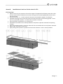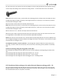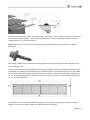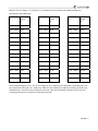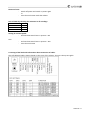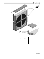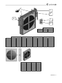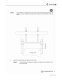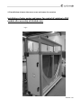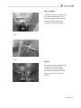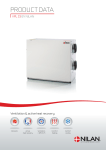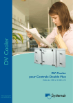
1
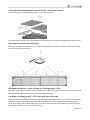
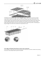
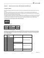
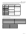
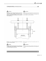
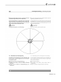
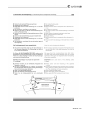
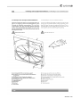
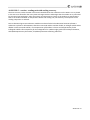
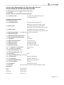
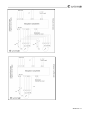
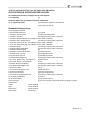
August 2014 Annex 4–12 for the User Manual Air handling units Danvent DV ‐ without control system GB Version 2.01.04 Master for translated versions of annex 4‐12 Original version for this air handling unit Overview Annex 4 – 12 for the User Manual version 2.01.04 is printed in this separate manual Annex 4 Assembly of base frame – height 150 mm for unit sizes 10 – 40 Annex 5 Assembly of base frame – height 150 mm for unit sizes 50 – 150 Annex 6 Assembly of base frame – height 250 mm for unit sizes 10 – 40 Annex 7 Assembly of base frame – height 250 mm for unit sizes 50 – 150 Annex 8 Installation of steel roof in the sizes 10‐150 Annex 9 Rotary exchanger – speed control and assembly of divided rotor Annex 10 Internal controller in the cooling compressor units – DVU and DVU‐C Annex 11 Menu for internal controller in the cooling compressor units ‐ DVU and DVU‐C Annex 12 Connection of fan motor and set‐up manual for Danfoss frequency converter Annex 1 – 3 for the User Manual printed on separate pages delivered with the unit Annex 1 Declaration of incorporation with production number Annex 2 Technical data – unique data for every unit Annex 3 Spare part lists Annex 13 for the User Manual printed on separate pages delivered with the unit Annex 13 Commissioning protocol ‐ proposal A DVD is delivered with every unit. On this DVD is a Word‐file of the commissionning protocol – proposal for modification by the installer. 2 Contents ANNEX4. ASSEMBLEBASEFRAMES–HEIGHT150MMFORUNITSSIZES10‐40......4—1 4.1 Base frame length 720 – 2420 [mm] Unit size 10‐40 ......................................................................................... 4—2 4.2 Base frame length 2420 – 4590 [mm] Unit size 10‐40 ....................................................................................... 4—3 4.3 Base frame length 4590 – 6200 [mm] Unit size 10‐40 ....................................................................................... 4—4 ANNEX5. ASSEMBLEBASEFRAMES–HEIGHT150MMFORUNITSSIZES50‐150...5—1 5.1 Base frame length 720 – 2420 [mm] Unit size 50‐DV150................................................................................... 5—2 5.2 Base frame length 2420 – 4590 [mm] Unit size 50‐150 .................................................................................... 5—3 5.3 Base frame length 4590 – 6200 [mm] Unit size 50‐150 ..................................................................................... 5—4 ANNEX6. ASSEMBLEBASEFRAMES–HEIGHT250MMFORUNITSSIZES10‐40......6—1 6.1 Base frame length 720 – 2420 [mm] Unit size 10‐40 ......................................................................................... 6—2 6.2 Base frame length 2420 – 4590 [mm] Unit size 10‐40 ....................................................................................... 6—3 6.3 Base frame length 4590 – 6200 [mm] Unit size 10‐40 ....................................................................................... 6—4 ANNEX7. ASSEMBLEBASEFRAMES–HEIGHT250MMFORUNITSSIZES50‐150...7—1 7.1 Base frame length 720 – 2420 [mm] Unit size 50‐150 ....................................................................................... 7—2 7.2 Base frame length 2420 – 4590 [mm] Unit size 50‐150 ..................................................................................... 7—3 7.3 Base frame length 4590 – 6200 [mm] Unit size 50‐150 ..................................................................................... 7—4 ANNEX8. INSTALLATIONOFSTEELROOFINTHESIZES10‐150....................................8—1 8.1 Overview ............................................................................................................................................................ 8—1 8.2 Mount rails. Units of size 10, 15, 20, and 25 ...................................................................................................... 8—2 8.3 Mount rails. Units of size 30 and units larger than size 30. ................................................................................ 8—2 8.4 Roof overhang along the long sides of the unit ................................................................................................. 8—3 8.5 Calculation of the overhang at the ends of the unit. Mount overhang profile – G1. ......................................... 8—3 8.6 Foam bands between rails and roof plates – mount roof plates. ...................................................................... 8—6 8.7 Foam bands between roof plates ....................................................................................................................... 8—6 8.8 Mount roof plates – some of them are overlapping by 2 ribs............................................................................ 8—6 8.9 Mount overhang profile – G5 on the other end of the unit. .............................................................................. 8—6 8.10 Mount side profiles and corners along the edges of the roof to protect persons ........................................... 8—7 8.11 Apply sealing on plate joints to ensure water resistance. ................................................................................ 8—7 ANNEX9. SPEEDCONTROLFORROTORANDASSEMBLYOFDIVIDEDROTOR.........9—1 9.1 Speed control ..................................................................................................................................................... 9—1 9.1.1 Selection of correct signal via the 4 DIP switch levers ....................................................................... 9—1 9.1.2 Indication of operation mode via red and green LED as well as test of motor .................................. 9—2 9.1.3 Copy of the label with information about connection of cables ........................................................ 9—3 9.2 Assemble the Systemair casing for DV60, DV80, DV100, DV120 og DV150 ....................................................... 9—4 9.3 Assemble divided rotor for DV 60, DV 80, DV 100, DV 120 og DV 150 .............................................................. 9—8 9.4 Assemble divided rotor for DV 190 og DV 240 ................................................................................................. 9—19 9.5 Installation of motor that turns rotor and sensor for rotation ........................................................................ 9—30 3 ANNEX10. INTERNALCONTROLLERINTHECOOLINGCOMPRESSORUNITS........10—1 10.1 DVU – section (cooling unit) ........................................................................................................................... 10—1 ........................................................................................................................................................................... 10—1 10.2 DVU‐internal controller for the cooling compressor system ......................................................................... 10—2 10.3 Background illumination of the display .......................................................................................................... 10—2 10.4 Potentiometer on the internal controller for the cooling compressor system .............................................. 10—2 10.5 Selection of menu........................................................................................................................................... 10—2 10.6 Change parameters ........................................................................................................................................ 10—2 10.7 Menu – drawing of the menu to guide the user ............................................................................................ 10—3 10.8 The start display ............................................................................................................................................. 10—3 10.9 Settings ........................................................................................................................................................... 10—3 10.10 Automatic resets of the high pressure switch .............................................................................................. 10—3 10.11 Polarity ......................................................................................................................................................... 10—3 10.12 Hotgas – setting of period ............................................................................................................................ 10—3 10.13 Limiter .......................................................................................................................................................... 10—3 10.14 Service .......................................................................................................................................................... 10—3 10.15 Manual operation ......................................................................................................................................... 10—3 10.16 Running hours and hotgas activations ......................................................................................................... 10—3 10.17 Alarm ............................................................................................................................................................ 10—3 10.17.1 Alarm ............................................................................................................................................ 10—3 10.17.2 Alarm Log ..................................................................................................................................... 10—4 10.18 Modified software in Danfoss frequency converter for the compressor ..................................................... 10—4 10.19 Maintenance ................................................................................................................................................ 10—4 10.20 Cooling capacity and absorbed power consumption in kW for compressor ‐ EER factor ............................ 10—5 10.21 Power consumption for the fans .................................................................................................................. 10—5 10.22 Data plate ..................................................................................................................................................... 10—5 10.23 DVU‐C – section ‐ cooling unit with cooling recovery .................................................................................. 10—6 ANNEX11. MENUFORINTERNALCONTROLLERINCOOLINGCOMPRESSOR........11—1 ANNEX12. CONNECTIONOFFANMOTORANDSET‐UPFORFREKV.CONV............12—1 12.1 Connection of fan motor ................................................................................................................................ 12—1 12.2 Set‐up for Danfoss FC101 for DV‐units with AC motors ................................................................................. 12—2 12.3 AC‐fan operation without thermistor for Danfoss FC101. ............................................................................. 12—4 12.4 Set‐up Danfoss FC101 for DV‐units with PM motors ..................................................................................... 12—5 4 Annex4. Assemblebaseframes–height150mmforunitssizes10‐40 A = Corner B = Splice C = Length profile D = Width profile Bilag 4—1 4.1Baseframelength720–2420[mm]Unitsize10‐40 Width profile type D Unit size DV‐10 DV‐15 DV‐20 DV‐25 DV‐30 DV‐40 Quantity 2 2 2 2 2 2 C Frame length [mm] 700‐770 770‐920 920‐1070 1070‐1220 1220‐1370 1370‐1520 1520‐1670 1670‐1820 1820‐1970 1970‐2120 2120‐2270 2270‐2420 Length [mm] 876 1026 1176 1326 1476 1626 Quantity 2 2 2 2 2 2 2 2 2 2 2 2 A Length [mm] 520 670 820 970 1120 1270 1420 1570 1720 1870 2020 2170 Quantity 4 4 4 4 4 4 4 4 4 4 4 4 Bilag 4—2 4.2Baseframelength2420–4590[mm]Unitsize10‐40 Width profile type D Unit size DV‐10 DV‐15 DV‐20 DV‐25 DV‐30 DV‐40 Quantity 3 3 3 3 3 3 Length [mm] 876 1026 1176 1326 1476 1626 C1 C2 A Frame length [mm] Quantity Length [mm] Quantity Length [mm] 2420-2570 2570-2640 2640-2790 2790-2940 2940-3090 3090-3240 3240-3390 3390-3540 3540-3690 3690-3840 3840-3990 3990-4140 4140-4290 4290-4440 4440-4590 2 2 2 2 2 2 2 2 2 2 2 2 2 2 2 1120 1270 1270 1270 1420 1420 1570 1570 1720 1720 1870 1870 2020 2020 2170 2 2 2 2 2 2 2 2 2 2 2 2 2 2 2 1200 1200 1270 1420 1420 1570 1570 1720 1720 1870 1870 2020 2020 2170 2170 B Quantity Quantity 4 4 4 4 4 4 4 4 4 4 4 4 4 4 4 2 2 2 2 2 2 2 2 2 2 2 2 2 2 2 Bilag 4—3 4.3Baseframelength4590–6200[mm]Unitsize10‐40 Width profile type D Unit size Quantity Length [mm] DV-10 DV-15 DV-20 DV-25 DV-30 DV-40 4 4 4 4 4 4 876 1026 1176 1326 1476 1626 A B Frame length [mm] Quantity C1 Length [mm] Quantity C2 Length [mm] Number C3 Length [mm] Qty Qty 4590-4740 4740-4890 4890-5040 5040-5110 5110-5260 5260-5410 5410-5560 5560-5710 5710-5860 5860-6010 6010-6160 6160-6200 2 2 2 2 2 2 2 2 2 2 2 2 1420 1570 1720 1720 1720 1720 1870 1870 1870 2020 2020 2020 2 2 2 2 2 2 2 2 2 2 2 2 1500 1570 1500 1720 1720 1720 1720 1870 1870 1870 2020 2020 2 2 2 2 2 2 2 2 2 2 2 2 1570 1500 1570 1500 1570 1720 1720 1720 1870 1870 1870 2020 4 4 4 4 4 4 4 4 4 4 4 4 4 4 4 4 4 4 4 4 4 4 4 4 Bilag 4—4 Annex5. Assemblebaseframes–height150mmforunitssizes50‐150 A = Corner B = Splice C = Spacer D = Length profile E = Spacer profile F = Width profile Bilag 5—1 5.1Baseframelength720–2420[mm]Unitsize50‐DV150 Width profile type F Unit size Quantity Length [mm] DV-50 DV-60 DV-80 DV-100 DV-120 DV-150 2 2 2 2 2 2 2020 2170 2170 2370 2590 2890 D A Frame length [mm] Quantity Length [mm] Quantity 700-770 770-920 920-1070 1070-1220 1220-1370 1370-1520 1520-1670 1670-1820 1820-1970 1970-2120 2120-2270 2270-2420 3 3 3 3 3 3 3 3 3 3 3 3 520 670 820 970 1120 1270 1420 1570 1720 1870 2020 2170 6 6 6 6 6 6 6 6 6 6 6 6 Bilag 5—2 5.2Baseframelength2420–4590[mm]Unitsize50‐150 Width profile type F Unit size Quantity Length [mm] Length [mm] DV-50 DV-60 DV-80 DV-100 DV-120 DV-150 2 2 2 2 2 2 2020 2170 2170 2370 2590 2890 940 1015 1015 1115 1225 1375 Width profile type E D1 Frame length [mm] Quantity 2420-2570 2570-2640 2640-2790 2790-2940 2940-3090 3090-3240 3240-3390 3390-3540 3540-3690 3690-3840 3840-3990 3990-4140 4140-4290 4290-4440 4440-4590 3 3 3 3 3 3 3 3 3 3 3 3 3 3 3 D2 Length Quantity [mm] 1120 1270 1270 1270 1420 1420 1570 1570 1720 1720 1870 1870 2020 2020 2170 3 3 3 3 3 3 3 3 3 3 3 3 3 3 3 A Length [mm] 1200 1200 1270 1420 1420 1570 1570 1720 1720 1870 1870 2020 2020 2170 2170 B C E Quantity Quantity Quantity Quantity 6 6 6 6 6 6 6 6 6 6 6 6 6 6 6 3 3 3 3 3 3 3 3 3 3 3 3 3 3 3 1 1 1 1 1 1 1 1 1 1 1 1 1 1 1 2 2 2 2 2 2 2 2 2 2 2 2 2 2 2 Bilag 5—3 5.3Baseframelength4590–6200[mm]Unitsize50‐150 Width profile type F Width profile type E Unit size Quantity Length [mm] Length [mm] DV-50 DV-60 DV-80 DV-100 DV-120 DV-150 2 2 2 2 2 2 2020 2170 2170 2370 2590 2890 940 1015 1015 1115 1225 1375 B C E Frame length [mm] Qty D1 Length [mm] Qty D2 Length [mm] Qty D3 Length [mm] Qty A Qtyl Qty Qty 4590-4740 4740-4890 4890-5040 5040-5110 5110-5260 5260-5410 5410-5560 5560-5710 5710-5860 5860-6010 6010-6160 6160-6200 3 3 3 3 3 3 3 3 3 3 3 3 1420 1570 1720 1720 1720 1720 1870 1870 1870 2020 2020 2020 3 3 3 3 3 3 3 3 3 3 3 3 1500 1570 1500 1720 1720 1720 1720 1870 1870 1870 2020 2020 3 3 3 3 3 3 3 3 3 3 3 3 1570 1500 1570 1500 1570 1720 1720 1720 1870 1870 1870 2020 6 6 6 6 6 6 6 6 6 6 6 6 6 6 6 6 6 6 6 6 6 6 6 6 2 2 2 2 2 2 2 2 2 2 2 2 4 4 4 4 4 4 4 4 4 4 4 4 Bilag 5—4 Annex6. Assemblebaseframes–height250mmforunitssizes10‐40 A = Corner B = Splice C = Length profile D = Spacer profile E = Width profile Bilag 6—1 6.1Baseframelength720–2420[mm]Unitsize10‐40 Width profile type E Unit size Quantity Length [mm] DV-10 DV-15 DV-20 DV-25 DV-30 DV-40 2 2 2 2 2 2 870 1020 1170 1320 1470 1620 C A Frame length [mm] Quantity Length [mm] Quantity 700-770 770-920 920-1070 1070-1220 1220-1370 1370-1520 1520-1670 1670-1820 1820-1970 1970-2120 2120-2270 2270-2420 2 2 2 2 2 2 2 2 2 2 2 2 520 670 820 970 1120 1270 1420 1570 1720 1870 2020 2170 4 4 4 4 4 4 4 4 4 4 4 4 Bilag 6—2 6.2Baseframelength2420–4590[mm]Unitsize10‐40 Width profile type E Quantity Length [mm] Length [mm] DV-10 DV-15 DV-20 DV-25 DV-30 DV-40 2 2 2 2 2 2 870 1020 1170 1320 1470 1620 870 1020 1170 1320 1470 1620 Spacer profile type D Unit size A B D Frame length [mm] Quantity C1 Length [mm] Quantity C2 Length [mm] Qty Qty Qty 2420-2570 2570-2640 2640-2790 2790-2940 2940-3090 3090-3240 3240-3390 3390-3540 3540-3690 3690-3840 3840-3990 3990-4140 4140-4290 4290-4440 4440-4590 2 2 2 2 2 2 2 2 2 2 2 2 2 2 2 1120 1270 1270 1270 1420 1420 1570 1570 1720 1720 1870 1870 2020 2020 2170 2 2 2 2 2 2 2 2 2 2 2 2 2 2 2 1200 1200 1270 1420 1420 1570 1570 1720 1720 1870 1870 2020 2020 2170 2170 4 4 4 4 4 4 4 4 4 4 4 4 4 4 4 2 2 2 2 2 2 2 2 2 2 2 2 2 2 2 1 1 1 1 1 1 1 1 1 1 1 1 1 1 1 Bilag 6—3 6.3Baseframelength4590–6200[mm]Unitsize10‐40 Width profile type E Spacer profile type D Unit size Quantity Length [mm] Length [mm] DV-10 DV-15 DV-20 DV-25 DV-30 DV-40 2 2 2 2 2 2 870 1020 1170 1320 1470 1620 870 1020 1170 1320 1470 1620 C1 C2 C3 A B D Frame length [mm] Qty Length [mm] Qty Length [mm] Qty Length [mm] Qty Qty Qty 4590-4740 4740-4890 4890-5040 5040-5110 5110-5260 5260-5410 5410-5560 5560-5710 5710-5860 5860-6010 6010-6160 6160-6200 2 2 2 2 2 2 2 2 2 2 2 2 1420 1570 1720 1720 1720 1720 1870 1870 1870 2020 2020 2020 2 2 2 2 2 2 2 2 2 2 2 2 1500 1570 1500 1720 1720 1720 1720 1870 1870 1870 2020 2020 2 2 2 2 2 2 2 2 2 2 2 2 1570 1500 1570 1500 1570 1720 1720 1720 1870 1870 1870 2020 4 4 4 4 4 4 4 4 4 4 4 4 4 4 4 4 4 4 4 4 4 4 4 4 2 2 2 2 2 2 2 2 2 2 2 2 Bilag 6—4 Annex7. Assemblebaseframes–height250mmforunitssizes50‐150 A = Corner C = Splice B = Splice D = Spacer E = Length profile F = Spacer profile G = Width profile Bilag 7—1 7.1Baseframelength720–2420[mm]Unitsize50‐150 Width profile type G Unit size Quantity Length [mm] DV-50 DV-60 DV-80 DV-100 DV-120 DV-150 2 2 2 2 2 2 1920 2070 2070 2270 2490 2790 E A B Frame length [mm] Quantity Length [mm] Quantity Quantity 700-770 770-920 920-1070 1070-1220 1220-1370 1370-1520 1520-1670 1670-1820 1820-1970 1970-2120 2120-2270 2270-2420 3 3 3 3 3 3 3 3 3 3 3 3 520 670 820 970 1120 1270 1420 1570 1720 1870 2020 2170 4 4 4 4 4 4 4 4 4 4 4 4 2 2 2 2 2 2 2 2 2 2 2 2 Bilag 7—2 7.2Baseframelength2420–4590[mm]Unitsize50‐150 Width profile type G Spacer profile type F Unit size Quantity Length [mm] Length [mm] DV-50 DV-60 DV-80 DV-100 DV-120 DV-150 2 2 2 2 2 2 1920 2070 2070 2270 2490 2790 935 1010 1010 1110 1220 1370 Frame length [mm] A B C D F Qty Length [mm] Qty Length [mm] Qty Qty Qty Qty Qty 2420-2570 2570-2640 2640-2790 2790-2940 2940-3090 3090-3240 3240-3390 3390-3540 3540-3690 3690-3840 3840-3990 3990-4140 4140-4290 4290-4440 4440-4590 3 3 3 3 3 3 3 3 3 3 3 3 3 3 3 1120 1270 1270 1270 1420 1420 1570 1570 1720 1720 1870 1870 2020 2020 2170 3 3 3 3 3 3 3 3 3 3 3 3 3 3 3 1200 1200 1270 1420 1420 1570 1570 1720 1720 1870 1870 2020 2020 2170 2170 4 4 4 4 4 4 4 4 4 4 4 4 4 4 4 2 2 2 2 2 2 2 2 2 2 2 2 2 2 2 3 3 3 3 3 3 3 3 3 3 3 3 3 3 3 1 1 1 1 1 1 1 1 1 1 1 1 1 1 1 2 2 2 2 2 2 2 2 2 2 2 2 2 2 2 C1 C2 Bilag 7—3 7.3Baseframelength4590–6200[mm]Unitsize50‐150 Width profile type G Spacer profile type F Unit size Quantity Length [mm] Length [mm] DV-50 DV-60 DV-80 DV-100 DV-120 DV-150 2 2 2 2 2 2 1920 2070 2070 2270 2490 2790 935 1010 1010 1110 1220 1370 A B C D F Frame length [mm] Qty E1 Length [mm] Qty E2 Length [mm] Qty E3 Length [mm] Qty Qty Qty Qty Qty 4590-4740 4740-4890 4890-5040 5040-5110 5110-5260 5260-5410 5410-5560 5560-5710 5710-5860 5860-6010 6010-6160 6160-6200 3 3 3 3 3 3 3 3 3 3 3 3 1420 1570 1720 1720 1720 1720 1870 1870 1870 2020 2020 2020 3 3 3 3 3 3 3 3 3 3 3 3 1500 1570 1500 1720 1720 1720 1720 1870 1870 1870 2020 2020 3 3 3 3 3 3 3 3 3 3 3 3 1570 1500 1570 1500 1570 1720 1720 1720 1870 1870 1870 2020 4 4 4 4 4 4 4 4 4 4 4 4 2 2 2 2 2 2 2 2 2 2 2 2 6 6 6 6 6 6 6 6 6 6 6 6 2 2 2 2 2 2 2 2 2 2 2 2 4 4 4 4 4 4 4 4 4 4 4 4 Bilag 7—4 Annex8. Installationofsteelroofinthesizes10‐150 8.1Overview Mount rails A1, B2, C3, D4, E5 on the unit for support of trapezoidal roof plates (mount also rails Y and Z on units of the size 30 and on units that are larger than size 30 longitudinally at the centre‐ line of the units). Place foam bands – P – on the horizontal rails A1, B2, C3 and D4 for support of roof plates. Calculate overhang of the roof at both ends of the unit and mount roof overhang profile – G1 on the first trapezoidal roof plate – F1 before the roof plate is mounted. Place and mount roof plates F1, F2, F3 and so on. Remember foam bands on the side laps between roof plates to prevent rainwater from passing through. Place roof overhang profile – G5 at the other end of the unit before the last roof plate is mounted. Mount sides and corners on the roof. Apply sealing where plates are joined to ensure water resistance ‐ even in stormy weather. Bilag 8—1 8.2Mountrails.Unitsofsize10,15,20,and25 Squeeze sealant in sufficient quantity between the underside of the rails A1, B2, C3, D4, E5 and the horizontal top side of the unit before the rails are mounted. This means that the rails are standing on sealant to achieve the tightest connection between rails and unit to prevent rainwater from passing under the rails and into the unit. Mount the rails A1 and B2 on the front side (the side with the inspection doors) – use the simple self‐drilling screws without the sealing washer – see the illustration of the screw below. Note: Rail B2 fits into the rail A1, and this offers the advantage that the rail B2 can be slid inside the rail A1 to adjust the length of rail B2 accurately to the length of the unit. In this way it is not necessary to spend time and effort cutting the rail B2. Mount the lower rails C3 and D4 on the back side of the unit. Note: Rail D4 fits into the rail C3, and this offers the advantage that the rail D4 can be slid inside the rail C3 to adjust the length of rail D4 accurately to the length of the unit. In this way it is not necessary to spend time and effort on cutting the rail D4. Mount vertical rail – E5 ‐ with the roof slope at each end of the unit It is important to place a screw in each hole – even though the number of holes for screws seems to be very large, a screw in each hole is necessary as the stress on the roof during stormy weather is extremely high. 8.3Mountrails.Unitsofsize30andunitslargerthansize30. On units of size 30 and on units that are larger than size 30, rails A1, B2, C3, D4, E5 must be mounted on the unit for support of trapezoidal roof plates, but also rails Y and Z must be mounted longitudinally at the centre‐line of the units to hold the trapezoidal roof plates. Squeeze sealant in sufficient quantity between the underside of the rails A1, B2, C3, D4, E5 and the horizontal top side of the unit before the rails are mounted. This means that the rails are standing on sealant to achieve the tightest connection between rails and unit to prevent rainwater from passing under Bilag 8—2 the rails and into the unit. Mount the rails A1 and B2 on the front side (the side with the inspection doors) – use the simple self drilling screws without the sealing washer – see the illustration of the screw below. Note: Rail B2 fits into the rail A1, and this offers the advantage that the rail B2 can be slid inside the rail A1 to adjust the length of rail B2 accurately to the length of the unit. In this way it is not necessary to spend time and effort cutting the rail B2. Mount the lower rails C3 and D4 on the back side of the unit. Note: Rail D4 fits into the rail C3, and this offers the advantage that the rail D4 can be slid inside the rail C3 to adjust the length of rail D4 accurately to the length of the unit. In this way it is not necessary to spend time and effort cutting the rail D4. Mount vertical rail – E5 ‐ with the roof slope at each end of the unit. Mount the rails Y and Z on the unit with the centre‐line of the rails exactly over the centre‐line of the unit. It is longitudinal on the middle of the units to hold the trapezoidal roof plates. Notice, that rail Z fits over the lower rail Y, and this offers the advantage that the rail Z can be slided on the rail Y to adjust the length of rail Z accurately to the length of the unit. In this way it is not necessary to spent time and effort on cutting the rail Z. It is important to place a screw in each hole – even though the number of holes for screws seems to be very large, a screw in each hole is necessary as the stress on the roof during stormy weather is extremely high. 8.4Roofoverhangalongthelongsidesoftheunit The roof plates are longer than the width of the unit to ensure sufficient overhang along the sides of the unit. The overhang is 100 mm along each side of the smallest unit – size 10. The overhang is 150 mm along each side of the units – size 15, 20, 25. The overhang is 175 mm along each side of the biggest units – including size 30. 8.5Calculationoftheoverhangattheendsoftheunit.Mountoverhangprofile–G1. The roof must be between 200 and 400 mm longer than the length of the unit to secure a roof overhang between 100 mm and 200 mm at the each of the 2 ends of the unit, and the length of this overhang must be calculated before the first roof plate is mounted. Bilag 8—3 The unit is delivered with 2 similar overhang profiles ‐ G1 and G5 ‐ one for each end of the roof. Mount one of the 2 roof overhang profiles – G on a trapezoidal roof plate. Use the self drilling, painted screws with sealing washers ‐ W ‐ see the illustration. Note: Foam bands ‐ P – are necessary between the overhang profile G1 and the roof plate F1. See the illustration. Self‐drilling, painted screws supplied with sealing washer for the mounting of the trapezoidal plate to the roof overhang profile. The total cover width of the trapezoidal roof plates always changes with the pitch of 207 mm between the trapezoidal ribs, making up a total length of the complete roof of ‐ for example 2070 mm, 2277 mm, 2484 mm and so on. We call this length of the total roof for RL and we call the total length of the complete unit for AL. The trapezoidal roof must always be longer than the unit, to obtain a reasonable overhang called – XX ‐ of the roof at both ends. In the table below you will find 40 different lengths of roofs (always changing with the 207 mm) and the lengths of units that are ideal for each of the 40 alternative roof lengths. Bilag 8—4 Measure the total length – AL of the unit – for example 5 metres between the 4982 and 5182 mm mentioned in the table below. AHU length AL Roof length RL AHU length AL Roof length RL AHU length AL Roof length RL 1670 – 1870 2070 4568 – 4768 4968 7466 – 7666 7866 1877 – 2077 2277 4775 – 4975 5175 7673 – 7873 8073 2084 – 2284 2484 4982 – 5182 5382 7880 – 8080 8280 2291 – 2491 2691 5189 – 5389 5589 8087 – 8287 8487 2498 – 2698 2898 5396 – 5596 5796 8294 – 8494 8694 2705 – 2905 3105 5603 – 5803 6003 8501 – 8701 8901 2912 – 3112 3312 5810 – 6010 6210 8708 – 8908 9108 3119 – 3319 3519 6017 – 6217 6417 8915 – 9115 9315 3326 – 3526 3726 6224 – 6424 6624 9122 – 9322 9522 3533 – 3733 3933 6431 – 6631 6831 9329 – 9529 9729 3740 – 3940 4140 6638 – 6838 7038 9536 – 9736 9936 3947 – 4147 4347 6845 – 7045 7245 9743 – 9943 10143 4154 – 4354 4554 7052 – 7252 7452 4361 ‐ 4561 7259 ‐ 7459 7659 4761 The mentioned length of roof – RL ‐ for this length of unit is 5382 mm (the delivered trapezoidal plates can be combined to this length ‐ RL = 5382 mm). 5382 mm minus 5000 mm is 382 mm overhang for both ends, and 382/2 mm = 191 mm is the overhang for each end. Place the trapezoidal roof plate F1 with the roof overhang profile G1 on rail E with an overhang of 191 mm. Bilag 8—5 8.6Foambandsbetweenrailsandroofplates–mountroofplates. Place foam bands P between profiles A1, B2, C3, D4 and roof plates. The trapezoidal roof plates are mounted with the self‐drilling, painted screws supplied with sealing washer. 8.7Foambandsbetweenroofplates Mount the self‐adhesive foam band – O ‐ on the underlapping rib for water resistant and effective sealing due to the small slope of the roof. 8.8Mountroofplates–someofthemareoverlappingby2ribs The width of each plate is always 1.035 mm and some of the plates have to overlap by 2 ribs to achieve the optimal total length of the whole roof — see the illustration above. 8.9Mountoverhangprofile–G5ontheotherendoftheunit. When the last trapezoidal plate (in this example F5) has been placed on the unit, the second roof overhang profile G5 must be pushed under the trapezoidal roof plate and mounted with the self‐drilling, painted screw with sealing washer. Mounting must be similar to the mounting of roof overhang profile under the trapezoidal roof plate at the other end of the unit. Bilag 8—6 8.10Mountsideprofilesandcornersalongtheedgesoftherooftoprotectpersons Profiles N and O with the rectangular holes are for the long and lower side of the roof because rain can escape through the holes. Mount the profiles type N first and the profile O last because the profile O goes over the profile N. Mounted in this order, the profile O can match the end of the roof and the surplus length of the profile O will just cover part of the previous profile N. Mount the profiles L and M along the long and higher front side of the roof. Mount the 4 protection corners. 8.11Applysealingonplatejointstoensurewaterresistance. Finish installation of the steel roof by sealing all plate joints with silicone to prevent rainwater from passing into the unit. See examples below of joints to be sealed. Bilag 8—7 Bilag 8—8 Annex9. Speedcontrolforrotorandassemblyofdividedrotor 9.1Speedcontrol The cabinet with the speed control system for the rotor is installed behind the inspection door in the rotor section. The cabinet contains the speed controller with all components, terminal blocks, LED displaying the operation mode, the dual position DIP switch with 4 sliding levers for programming the rotor motor signal and a button for the activation of the test mode. Through the different combinations of the 4 sliding levers of this dual position DIP switch, the correct signal is available for the 3 different motors used for the 14 sizes of air handling units. The sliding levers are set and the function is checked at the factory. The positions of the levers appear from the tables below. 9.1.1 Selection of correct signal via the 4 DIP switch levers The 4 DIP switch levers Position Function Code Up Active = ON 1 Down Deactivated = OFF 0 The factory sets the positions of the 4 DIP switch levers for the maximum of 10 revolutions per minute for standard temperature exchangers and for hygroscopic exchangers. The position of each DIP switch lever is shown below. DV Diameter of DIP switch position Motor pulley 10 15 20 25 30 40 50 60 80 100 120 150 190 240 50 50 50 65 65 65 71 80 85 95 106 112 132 140 0000 90TYD‐S214‐M 2.8Nm 1000 0100 120TYD‐S214‐M 5.5Nm 0010 120TYD‐S214‐L 7.5Nm Annex 9—1 The factory sets the positions of the 4 DIP switch levers for the maximum of 20 revolutions per minute for sorption exchangers. The position of each DIP switch lever is shown below. DV Diameter of DIP switch position Motor pulley 10 15 20 25 30 40 50 60 80 100 120 150 190 240 50 87 87 107 107 107 118 118 140 150 150 160 160 160 1000 0100 90TYD‐S214‐M 2.8Nm 120TYD‐S214‐M 5.5Nm 1100 1010 0110 120TYD‐S214‐L 7.5Nm 9.1.2 Indication of operation mode via red and green LED as well as test of motor The LED is in the cover of the cabinet. LED indication Value No indication Power off Green Ordinary operation Green – flashes Ready for operation Constant green and red indication for activated rotor Magnet on the rotor has activated rotor guard guard Constant green and fast red flashes Restart sequence active Red Rotor guard has not been activated Number of red flashes in series Value 1 Output current limit 2 Over voltage 3 Under voltage 4 Failure in the controller 5 Communication failure Annex 9—2 Restart of rotor: ‐ Switch off power and switch on power again or ‐ Press the test button inside the cabinet Test of motor by checking the resistance in all 3 vindings Motor sizes Ohm 90TYD‐S214‐M 40Ω 120TYD‐S214‐M 18Ω 120TYD‐S214‐L 10Ω Setting of constant speed: ‐ Set fourth DIP switch lever in position ‐ ON Test: ‐ Set fourth DIP switch lever in position – ON ‐ Press the test button 9.1.3 Copy of the label with information about connection of cables This self‐adhesive label is always placed on the cover of the cabinet. The text is always in English. Annex 9—3 9.2AssembletheSystemaircasingforDV60,DV80,DV100,DV120ogDV150 Size DV 60 DV 80 DV 100 DV 120 DV 150 A 2170 2320 2520 2890 3040 B 1640 1790 1940 2090 2240 C 520 588 588 558 558 Annex 9—4 Annex 9—5 A1 Size DV 60 DV 80 DV 100 DV 120 DV 150 A1 Quantity 4 4 4 4 4 Length (mm) 1014 1164 1314 1464 1614 Annex 9—6 B1 B5 B4 B2 B3 Size DV 150 B5 Number # 2 12100510 Size DV 60 DV 80 DV 100 DV 120 DV 150 B1 Quantity 1 1 1 1 1 # 10122310 10122610 10122710 10122810 10122910 B2 Quantity ‐ 4 4 4 4 B3 Quantity ‐ 4 4 4 4 # ‐ 11200400 11200410 12100410 11200420 # ‐ 21000200 21000210 21000230 21000220 B4 Quantity # 1 10722310 1 10722610 1 10722710 1 10722810 1 10722910 Size DV 60 DV 80 DV 100 DV 120 DV 150 A 2170 2320 2520 2890 3040 C 520 588 588 558 558 D 2240 2540 2840 3140 3440 Annex 9—7 9.3AssembledividedrotorforDV60,DV80,DV100,DV120ogDV150 Annex 9—8 Annex 9—9 Annex 9—10 Annex 9—11 Annex 9—12 Annex 9—13 Annex 9—14 Annex 9—15 Annex 9—16 Annex 9—17 Annex 9—18 9.4AssembledividedrotorforDV190ogDV240 Annex 9—19 Annex 9—20 Annex 9—21 Annex 9—22 Annex 9—23 Annex 9—24 Annex 9—25 Annex 9—26 Annex 9—27 Annex 9—28 Annex 9—29 9.5Installationofmotorthatturnsrotorandsensorforrotation Installation of rotor motor and sensor for control of rotation in DVC module after assembly of divided rotor Fig. 1 Annex 9—30 Fig.2 Fig. 2 By delivery of a DVC module with divided rotor, the motor is installed before delivery to the customer Fig.3 Fig.4 Fig.5 Fig. 3, 4 and 5 The motor and console is secured to the motor plate by 4 shock absorbers mounted by M8 bolts. Fig.6 Fig. 2 og 6 The drive belt must be placed around the rotor and in the center position of the rotor. Observe brackets for assembly of the rotor segments. Annex 9—31 Fig. 7 and 8 . Sensor for control of rotation must be installed by the installer. The distance must be 1‐4 mm from the outmost brackets used for the assembly of the rotor segments. Fig.8 1 ‐ 4mm Fig.9 Fig. 9 Please be aware of the height of the brackets that are used for the assembly of the rotor segments. Please turn the rotor to check the sensor do not touch any of the brackets. Annex 9—32 Annex10. Internalcontrollerinthecoolingcompressorunits 10.1DVU–section(coolingunit) The air handling unit section – DVU – is a separate section in the air handling unit, and the section contains a complete stand‐alone cooling compressor system. The system has been started, adjusted and optimized before the delivery. The refrigerant is evaporated directly in the cooling coil and the cooling capacity is regulated automatically and steplessly between 10 and 100 %. The system is delivered with the HFC refrigerant R‐407C in the circuit. Internally in the section a DVU‐internal controller ‐ LMC251 ‐ and complete control system take care of all safety functions as well as the frequency converter regulated compressor that creates exactly the cooling capacity ordered by the main air handling unit controller via the very common 0‐10V DC signal. When the demand for cooling occurs in the room, the main air handling unit controller sends a start signal and a signal exceeding 0 volt to the cooling compressor system. When the signal exceeds 1.5 volt the cooling compressor starts. After start‐up the capacity is regulated between 10 and 35 % by the hotgas valve (HGV in the illustration below) in on/off in sequences with the cooling compressor at the lowest number of revolutions. When more than 35 % of the cooling capacity is demanded (signal exceeds more than 3,5 volt) the hotgas valve closes, the cooling capacity is regulated by the frequency converter (FC in the illustration below) to the strictly necessary revolutions of the compressor. By declining demand with the compressor at the lowest revolutions, the hotgas valve is regulated on/off in sequences, when the demand is less than 34 %. The cooling compressor stops when the demand is less than 10 %. To avoid that the compressor stops because the high pressure switch (Hp in the illustration below) cuts off, an automatic capacity reduction system is installed. The capacity reduction system consists of a pressure transducer (P in the illustration below) installed in the high pressure pipe between the compressor and the condenser and software in the DVU‐internal controller that reduces the revolutions of the compressor to avoid that the pressure after the compressor develops to the cut‐off pressure of the high pressure switch – the system does not stop; it will always remain cooling to some extent.Air volume capacities for supply fan and for exhaust fan are not regulated by the built‐in controller – LMC251 ‐ for the cooling system, but by the main air handling unit controller. The technician from a certified installer of cooling units must agree with the installer of the ventilation system and the main air handling unit controller that the air volumes for the system are not going to exceed the maximum or to be lower than the recommended minimum mentioned below in section 3.2.5.18 in this manual Extract Supply Analog in 3*400 VAC RS485 COM Digital in CapReg On/of Alarm out Relay out Digital‐ in Relay‐ out Analog‐ in Relay out Alarm Annex 10—1 10.2DVU‐internalcontrollerforthecoolingcompressorsystem Two LEDs (light diodes) are placed on the DVU‐internal controller and each of the LEDs can be on or flash green, red or orange. During normal conditions a permanent green light indicates that everything is normal, orange indicates alternative running mode while red indicates alarm. Green Orange LED Off Green Orange Red Red flashing flashing flashing Upper LED Off‐signal from .. main AHU controller On‐signal from main AHU controller .. .. .. .. Lower LED Compressor active .. Hotgas active Alarm .. .. .. Priorities of the collars are: 1. 2. 3. 4. 5. 6. Red (highest priority) Red Flashing Orange Orange Flashing Green Gren Flashing (Lowest priority). 10.3Backgroundilluminationofthedisplay Background illumination of the display switches on automatically when the potentiometer is turned or pressed. The illumination switches off one minute after the last activation of the potentiometer. By alarm the illumination flashes until the alarm is acknowledged 10.4Potentiometerontheinternalcontrollerforthecoolingcompressorsystem The potentiometer is the only tool for the selection of menus and for changing parameters in the DVU‐ internal controller. The potentiometer is at the right side of the display. The potentiometer has 3 functions: 1. Turn clockwise : Go to the next menu item or increase parameter value 2. Turn anticlockwise : Go to the previous menu item or decrease parameter value 3. Press : Select menu, start change of parameter or acknowledge and store new value 10.5Selectionofmenu Turn the knob to change menu. When an arrow is shown to the right at the bottom of the display, the menu has a submenu. The submenu is activated by pressing the knob once. If the knob is turned in the submenu you will scroll between the items in the submenu. Leave the submenu by turning the potentiometer clockwise or anticlockwise until the "menu up" is shown. Press to leave the submenu. 10.6Changeparameters Turn the knob until the required parameter is shown in the display. Press the knob and turn until the required value is shown. Press the button once more to acknowledge and store the value. Flashing parameter value in the display indicates that changes are being made and not yet acknowledged and stored. Annex 10—2 10.7Menu–drawingofthemenutoguidetheuser Drawing of the menu appears from section 12 10.8Thestartdisplay The start picture shown when the potentiometer has not been activated for 10 minutes In: nnn% shows the capacity ordered by the main air handling unit controller. Out: nnn% shows the capacity ordered by this internal controller ‐ LMC251 – of the compressor. 10.9Settings About basic settings in the submenus in the LMC251 10.10Automaticresetsofthehighpressureswitch This is about the maximum number of automatic resets of the high pressure switch that are acceptable within one hour. If this number is exceeded, the unit will be shut down until the high pressure switch has been reset manually. 10.11Polarity The Alarm polarity can be set to”Normally Open” or ”Normally Closed”. 10.12Hotgas–settingofperiod This is the number of seconds that the hotgas valve is open. The period is relatively long, but the supply temperature is not oscillating at all and the stability of the supply temperature is sufficient. The number of seconds is a factory setting that should not be reduced. Reduction of the number of seconds will not improve the stability of the temperature to a degree that can be proven by measurements. If the number of seconds is reduced, the number of times that the valve is opened and closed will be increased – maybe considerably, and the valve could be worn out prematurely. 10.13Limiter DeltaMax is the maximum acceptable change in % / second of the actual cooling capacity. 10.14Service In this menu information about the software version in the controller as well as 2 submenus – “Manual operation” and “Runtime” 10.15Manualoperation When the menu – Manual operation ‐ is activated, the technician is able to control the operation manually, when the start signal from the main air handling unit controller is on (start signal is just potential free connection of the two terminals – 3&4). This procedure is relevant for the test during the annual maintenance with the control of all safety and regulation procedures or after installation of new components. If no new settings have been carried out on the controller for 10 minutes, the menu – Manual operation – is deactivated, and the unit returns to the automatic mode. 10.16Runninghoursandhotgasactivations In this menu the number of running hours for the compressor, and the number of activations of the hotgas valve can be read. This information is valuable for the maintenance. 10.17Alarm 10.17.1 Alarm Show the actual alarm with alarm number. Annex 10—3 10.17.2 Alarm Log The last 15 alarms are logged and it is not possible to delete them. No time‐stamps on the stored alarms. 10.18ModifiedsoftwareinDanfossfrequencyconverterforthecompressor The standard settings in the Danfoss frequency converter have been changed in 2 menu items, because the safety functions in these menus are transferred to the DVU‐internal controller ‐ LMC251; ‐ In the menu item 5‐10 Terminal 18, digital input (start), the value must be changed from 8 to 0. ‐ In the menu item 5‐12 Terminal 27, digital input (free running inverted), the value must be changed from 2 to 0. Especially for compressor VTZ 121 in DVU 25 and DVU 30 as well as for the compressor VTZ 086 in DVU 20 In addition to the above‐mentioned modifications, the modifications below are necessary for the compressor VTZ 121 in DVU 25 and DVU 30; ‐ Value in menu item 1‐90 changed to 2 ‐ Value in menu item 1‐93 Terminal 54 changed to 2 Usually the Danfoss frequency converter keeps the change to the standard factory setting stored for ever, but if the software has been turned back to the original factory setting for some reason, the above‐ mentioned modifications must be carried. If the modifications are not carried out correctly, the compressor will not be switched on at all. 10.19Maintenance General maintenance must be carried out according to national and local regulations by a skilled technician from a certified company. List of spare parts as well as datasheets from the manufacturers are available on the CD delivered with the unit. Air volume, cooling capacity, refrigerant content DVU‐25 DVU‐30 DVU‐40 DVU‐10 DVU‐15 DVU‐20 Width in mm 970 1120 1270 1420 1570 1720 Height in mm 970 1120 1270 1420 1570 1720 Length in mm 970 1120 1120 1270 1270 1270 Weight in kg 190 240 280 375 400 475 Power supply – 3phase + N+ 3x400V+ 3x400V 3x400V + 3x400V + 3x400V 3x400V + PE N + PE, + N + N + PE, N + PE, +N + PE, N +PE, 10A PE, 16A 20A 25A 25A 32A Nominal air volume, m3/s 0.8 1.11 1.65 2.33 2.65 3.33 Minimum air volume, m3/s 0.3 0.4 0.5 0.6 0.9 1.0 Test pressure, bar 28.6 28.6 28.6 28.6 28.6 28.6 Refrigerant R407C R407C R407C R407C R407C R407C Refrigerant content in kg 3 3 4.5 6 6 9.8 Cooling capacity at nominal 11.1 kW 15.7 kW 23.3 kW 33.8 kW 36.7 kW 47.3 kW air volume when: Outdoor 28°C/50% r. H. Room 25°C/50% r. H. Supply air 18°C/90% r. H. Nominal air volume = highest air volume, where outdoor air is 28 ºC/50% r.H. and is chilled by 10 ºC. Annex 10—4 10.20CoolingcapacityandabsorbedpowerconsumptioninkWforcompressor‐EER factor Cooling capacity and absorbed power consumption data is listed in the table below for calculation of the energy performance of the building. Cooling capacity and absorbed power consumption are listed for 3 levels – minimum – medium – and maximum revolutions for the cooling compressor when the evaporation temperature is 10 °C and condensation temperature is 50 °C. Maximum cooling capacity at nominal air flow when supply air flow is equal to exhaust air flow, outdoor 28 °C/50% r.H., indoor 25 °C/50% r.H. and supply air 18 °C/90% r.H.. Cooling capacity in kW/absorbed power consumption in kW and EER‐value – all at nominal air volume DVU‐10 DVU‐15 DVU‐20 DVU‐25 DVU‐30 DVU‐40 Minimum – 35 Hz 5.6/1.2 ‐ 7.7/1.9 ‐ 11.5/2.2 ‐ 15.7/3.3 ‐ 18.5/3.8 ‐ 23.2/4.5 ‐ 4.5 4.1 5.2 4.7 4.9 5.1 Medium – 60 Hz 8.9/2.3 ‐ 12.4/3.4 ‐ 18.5/4.3 ‐ 27.5/7.1 ‐ 29.6/7.1 ‐ 39.7/9.4 ‐ 3.8 3.7 4.4 3.9 4.2 4.2 Maximum – 90 Hz 11.1/3.7 ‐ 15.7/5.4 ‐ 23.3/6.9 ‐ 33.8/11.1 ‐ 36.7/11.3 ‐ 47.3/13.2 ‐ 3.0 2.9 3.4 3.0* 3.2* 3.6 *85 Hz The minimum capacity is selected at the frequency converter output at 35 Hz (the compressor in the DVU 20, 25/30 and 40 can reduce the capacity further to even lower revolutions at 30 Hz). At the lowest revolutions the hotgas valve opens to reduce the capacity further – the lowest cooling capacity equals 10 % of the capacity at 90 Hz. If the temperature and humidity conditions on the site deviate from the above‐ mentioned conditions, accurate values can be calculated in the design programme SystemairCAD. Systemair is ready to provide you with a print‐out, if a copy of calculation of the specific unit in the SystemairCAD is not available. 10.21Powerconsumptionforthefans The unit section ‐ DVU ‐ is one of several sections in the air handling unit, and the supply air fan for the evaporator as well as the exhaust air fan for the condenser, heat recovery and heating coil are installed in other sections. The energy performance for the complete unit including the consumption of the fans is always calculated in the design programme SystemairCAD. Systemair is ready to provide you with a print‐ out, if a copy of the calculation of the specific unit in the SystemairCAD is not available. 10.22Dataplate The data plate for the cooling unit is mounted inside the unit section – DVU – behind one of the doors. An example of the data plate is shown below. DVU‐40 Manufaturing year Serial Number: Refrigerant Quantity of refrigerant Compressor Supply voltage Running load ampere Main circuit breaker Short circuit level min Short circuit level max Max working temperature Min working temperature Max working pressure Testing pressure 407C 9.8 kg Danfoss VTZ171 3*400 V + N + PE 31.5 A 35 A 1,0 kA 7,3 kA 55°C ‐40°C 26 bar 28.6 bar Annex 10—5 10.23DVU‐C–section‐coolingunitwithcoolingrecovery The DVU‐C unit is similar the DVU unit but with the difference that condenser on the DVU‐C unit is placed in the extract air flow after the rotary heat exchanger with the advantage that the outdoor air is precooled by the rotary heat exchanger, when the extract air temperature is lower as the outdoor air temperature. Due to the reduced outdoor air temperature before the cooling coil, the electricity consumption of the cooling compressor is reduced. DVU‐C sektionen ligner DVU sektionen med den markante forskel at kondensator batteriet på DVU‐C sektionen er placeret i luftstrømmen efter den roterende veksler med den fordel, at indsuget udeluft bliver afkølet via den roterende veksler, når temperaturen på fraluften er lavere end temperaturen på den indsugede udeluft. Når temperatur på det indsugede luft er sænket nogle grader før fordamper batteriet, skal kølekompressoren yde mindre, så kølekompressorens elforbrug reduceres. Annex 10—6 Annex11. Menuforinternalcontrollerincoolingcompressor Menupoint Submenu Submenu In: nnn% Out: nnn% SETTINGS Min Default Max Comments 0 0 ### ### 100 100 Set point for capacity level Actual capacity level MENU UP Number of automatic resets of high pressure switch off’s within one hour before activation of alarm. AUTORES. 3 POLARITY NC HOTGAS MENU UP HGDuty TIME NNm MENU UP 0 3 3 NC NC NO 10 60 120 0.1 0.5 10 Polarity of BMS set to “Normally Open” or ”Normally Closed” LIMITER MENU UP DeltaMax %/s MENU UP Max increase og cooling capacity in % per sec. MENU UP SERVICE MENU UP LMC 251 Ver 1.05 MANUAL Software Version MENU UP FC OFF HOTGAS OFF LIQUID.V OFF CPR.HEAT OFF CTS OFF MENU UP OFF OFF ON Manuel operation of frequency converter OFF OFF ON Manuel operation of Hot Gas valve OFF OFF ON Manual operation of LIQUID valve OFF OFF ON Manual operation of COMPRESSOR HEAT OFF OFF ON Manual operation of BMS switch 0 ######## 1E+07 Compressor running time 0 ######## 1E+07 Hot Gas valve activation RUNTIME MENU UP COMPRESS nnnnnnnh HOTGAS nnnnnnn MENU UP MENU UP Alarm MENU UP ALARM ## Alarm AlarmLog Alarm name and number MENU UP AL 1: ## Alarm AL 2: ## Alarm MENU UP List over the last 15 alarms MENU UP MENU UP Annex 11—1 Annex12. Connectionoffanmotorandset‐upforfrekv.conv. 12.1Connectionoffanmotor Delta connection – for low speed – is shown to the left, and star connection – for high speed – is shown to the right. Annex 12—1 12.2Set‐upforDanfossFC101forDV‐unitswithACmotors SETUP IS DONE IN FACTORY BEFORE DELIVERY To reload Systemair factory settings from the control panel: 0‐50: LCP Copy: [2] Systemair factory set‐up is based on Danfoss initialization. 14‐22: Operation mode: [2] Initialisation (Danfoss Initialisation) Turn power off and on. Systemair factory set‐up: 0‐01: Language selection: 1‐03: Torque characteristic: Single fan: [3] Auto‐Energy optim. With twin fan set‐up: [1] Variable Torque 1‐20: Motor Power: According to motor plate / order papers With twin fan set‐up total power must be used 1‐24: Motor Current: According to motor plate / order papers With twin fan set‐up total current must be used 1‐25: Motor Nominal Speed: According to motor plate / order papers 1‐42: Motor Cable Length: 3m 1‐50: Motor Magnetisation at zero speed.: 0 % 1‐52: Min. Speed Normal Magnetisation: 10 Hz 1‐73: Flying Start: [0] Disabled 1‐90: Motor Thermal Protection: [2] Thermistor trip 3‐15: Reference 1 Source: [2] Analog input AI54 1‐93: Thermistor Source: [1] Analog input AI53 3‐03: Maximum Reference: Max. Hz from order papers 3‐16 + 3‐17: Reference 2‐ and 3 Source: [0] No function 3‐41 + 342: Ramp 1 up and down: 20 Sec. 4‐19: Max. Output Frequency: 90Hz 4‐14: Motor Speed High Limit: 90Hz 4‐18: Current limit: 100 % 5‐12: Terminal 27 Digital input: [0] No operation 5‐40.0: Function Relay: [3] Drive ready/remote 5‐40.1: Function Relay: [3] Drive ready/remote 6‐25: Terminal 54 High Reference: Max. Hz from order papers 14‐03: Over modulation: [1] Active 14‐20: Reset Mode: [2] Automatic reset x 2 0‐50: LCP Copy: [1] All to LCP (Copy of Systemair factory settings to panel) Connections: 0‐10V: terminal 54‐55 Start: terminal 12‐18 Thermistor: terminal 50‐53 Drive ready: terminal 1‐2 Annex 12—2 Annex 12—3 12.3AC‐fanoperationwithoutthermistorforDanfossFC101. Systemair factory set‐up is based on Danfoss initialization. 14‐22: Operation mode: [2] Initialisation (Danfoss Initialisation) Turn power off and on. Systemair factory set‐up: 0‐01: Language selection: 1‐03: Torque characteristic: 1‐20: Motor power: 1‐24: Motor Current: 1‐25: Motor Nominal Speed: 1‐29: Automatic motor adption (AMA): 1‐42: Motor Cable Length: 1‐50: Motor Magnetisation at zero speed.: 1‐52: Min. Speed Normal Magnetisation: 1‐73: Flying start: 5‐40.0: Function Relay: 14‐03: Over modulation: 14‐20: Reset Mode: 0‐50: LCP Copy: [3] Auto‐Energy optim. According to motor plate According to motor plate According to motor plate [1] Kompl.motor adaption to (Turn power off and on.) Order specific 0 % 10 Hz [0] Deaktivated [3] Drive ready/remote [1] Active [2] Automatic reset x 2 [1] All to LCP (Copy of Systemair factory settings to panel) Connections: 0‐10V: Start: Drive ready: Jumper terminal 54‐55 terminal 12‐18 terminal 1‐2 terminal 12‐27 Annex 12—4 12.4Set‐upDanfossFC101forDV‐unitswithPMmotors SETUP IS DONE IN FACTORY BEFORE DELIVERY To reload Systemair factory settings from the control panel: 0‐50: LCP Copy: [2] Systemair factory set‐up is based on Danfoss initialization. 14‐22: Operation mode: [2] Initialisation (Danfoss Initialisation) Turn power off and on. Systemair factory set‐up: 0‐01: Language selection: 1‐06: Clockwise Direction: [1] Inverse 1‐10: Motor Construction: [1] PM, non‐salient SPM 1‐24: Motor Current: According to motor plate / Schedule 1‐25: Motor Nominal Speed: According to motor plate / Schedule 1‐26: Motor Cont. Rated torque: According to motor plate / Schedule 1‐30: Stator Resistance (Rs): According to motor plate / Schedule 1‐37: d‐axis inductance (Ld): According to motor plate / Schedule 1‐39: Motor Poles: According to motor plate / Schedule 1‐40: Back EMF at 1000 RPM: According to motor plate / Schedule 3m 1‐42: Motor Cable Length: 1‐90: Motor Thermal Protection: [2] Thermistor trip 3‐15: Reference 1 Source: [2] Analog input AI54 1‐93: Thermistor Source: [1] Analog input AI53 3‐03: Maximum Reference: According to motor plate / Schedule 3‐16 + 3‐17: Reference 2‐ and 3 Source: [0] No function 3‐41 + 3‐42: Ramp 1 Up and down: 30 sec. 4‐19: Max. Output Frequency: According to motor plate / Schedule 4‐14: Motor Speed High Limit: According to motor plate / Schedule 4‐18: Current limit: 115 % 5‐12: Terminal 27 Digital input: [0] No operation 5‐40.0: Function Relay: [3] Drive ready/remote 5‐40.1: Function Relay: [3] Drive ready/remote 6‐25: Terminal 54 High Reference: According to motor plate / Schedule 14‐03: Over modulation: [1] Active 14‐20: Reset Mode: [2] Automatic reset x 2 0‐50: LCP Copy: [1] All to LCP (Copy of Systemair factory settings to panel) Connections: 0‐10V: terminal 54‐55 Start: terminal 12‐18 Thermistor: terminal 50‐53 Drive ready: terminal 1‐2 Annex 12—5 Schedule for PM motor parameters Menu: Motor Type Number 124 Amp Name plate 125 Motor RPM rated 126 Nm Name plate HPS 71 3800 18 HPS 71 3700 28 HPS 71 3300 18 HPS 71 3200 30 HPS 71 2900 21 HPS 71 2800 40 HPS 71 2500 29 HPS 71 2350 38 HPS 90 2650 64 HPS 90 2350 76 HPS 90 2100 63 HPS 90 2050 100 HPS 90 1850 84 HPS 90 1900 136 HPS 90 1700 106 HPS 112 1550 108 HPS 112 1700 145 HPS 112 1350 135 HPS 112 1500 187 HPS 112 1000 140 HPS 132 1250 199 HPS 132 1000 202 HPS 132 1150 300 HPS 132 930 273 1,8 2,8 1,8 3 2,1 4 2,9 3,8 6,4 7,6 6,3 10 8,4 13,6 11 10,9 14,5 13,5 18,7 14 19,9 20,2 30 27,3 3800 3700 3300 3200 2900 2800 2500 2350 2650 2350 2100 2050 1850 1900 1700 1550 1700 1350 1500 1000 1250 1000 1150 930 2 3,6 2,6 4,2 3,3 6,14 5 7,3 9,6 13 10,5 19 16 26 22 32 39 44 54 51 69 77 104 118 130 137 Ohm [Rf‐f] mH [Lf‐f] 3,600 1,580 5,750 1,850 4,500 1,675 3,000 2,300 1,250 0,800 1,500 0,810 1,050 0,575 0,575 0,750 0,465 0,490 0,295 0,475 0,255 0,315 0,235 0,280 13,00 6,10 20,50 7,25 14,75 6,75 11,00 9,35 10,75 10,00 14,75 8,75 11,50 7,25 7,25 8,75 5,45 6,45 4,35 7,00 7,60 9,25 8,00 9,75 139 Poles 6 6 6 6 6 6 6 6 8 8 8 8 8 8 8 6 6 6 6 6 6 6 6 6 140 303 + 625 414 + 419 Bemf @ Max 1000 Max Hz motor Hz 67 79 85 84 95 95 105 115 87 103 101 115 110 110 117 178 162 197 175 242 210 230 230 261 215 191 170 161 143 144 129 120 182 159 142 140 127 127 116 80 88 69 76 54 65 51 58 46 219 204 182 176 160 154 138 129 194 172 154 150 136 139 125 85 94 74 83 55 69 65 65 65 Annex 12—6 Annex 12—7 Annex 12—8 Systemair A/S Ved Milepælen 7 DK‐8361 Hasselager Tel. 0045 8738 7500 www.systemair.dk Annex 12—9