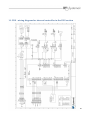
1
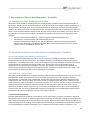
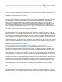
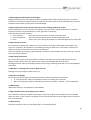
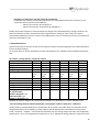
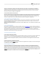
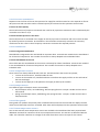
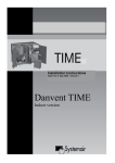
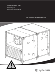
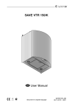
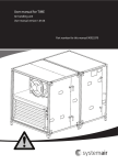
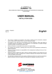
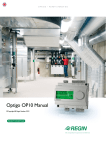
Danvent DV, Danvent TIME
Air Handling Units
GB
User Manual
1
2
Introduction
Detailed table of contents on the following pages
1. Manufacturer
2. Declaration of conformity
3. Description of the air handling units
4. Intended use, noise and vibration
5. Protection and safety measures
6. Electrical connection
7. Plumbing
8. Accompanying documents
9. Start-up
10. Commissioning
11. DVU - Wiring diagram for internal controller
12. Menu for internal controller in the DVU
3
Contents
1. MANUFACTURER ...................................................................................................................................................................... 8
1.1 Manufacturer, supplier data .......................................................................................................................... 8
1.2 Name of machines ......................................................................................................................................... 8
2. DECLARATION OF CONFORMITY ......................................................................................................................................... 9
3. DESCRIPTION OF THE AIR HANDLING UNITS – 8 MODELS ...................................................................................... 10
3.1 Common for all air handling unit models ...................................................................................................... 10
3.2 Specific data about each model of the air handling unit – 8 models.............................................................. 10
3.2.1 DV unit without switchboard/control system ................................................................................................. 10
3.2.2 TIME unit – indoor model................................................................................................................................ 10
3.2.3 TIME unit – outdoor model ............................................................................................................................. 11
3.2.4 DV unit with switchboard/control system – delivered in several sections ..................................................... 11
3.2.5 DV unit with switchboard/control system – delivered as one section on base frame .............................. 12
3.2.6 DV unit with switchboard and control components, without controller – delivered in several sections ....... 12
3.2.7 DV unit with switchboard and control components, without controller – delivered as one section on base
frame ........................................................................................................................................................................ 13
3.2.8 DVU – section (cooling unit) ............................................................................................................................ 14
4. INTENDED USE, NOISE AND VIBRATION ........................................................................................................................ 20
4.1. Intended use and range of applications ....................................................................................................... 20
4.2 Unintended use and misuse – inappropriate applications for the machine ................................................... 20
4.3 Air handling unit in operation ...................................................................................................................... 20
4.4 Maintenance, repair, dismantling and disposal ............................................................................................ 20
4.4.1 Protective measures........................................................................................................................................ 20
4.4.2 Sharp edges ..................................................................................................................................................... 20
4.4.3 Filters ............................................................................................................................................................... 20
4.5 Disposal measures ....................................................................................................................................... 20
4.5.1 DVU – cooling system ...................................................................................................................................... 21
4.5.2 Sharp edges ..................................................................................................................................................... 21
4.6 Use/operation of the machine ..................................................................................................................... 21
4
4.7 Prohibited use of the machine ..................................................................................................................... 21
4.8 Noise and vibration ...................................................................................................................................... 21
5. PROTECTION AND SAFETY MEASURES .......................................................................................................................... 22
5.1 Protection measures and additional protection measures ............................................................................ 22
5.2 Necessary protection measures prior to start-up. ......................................................................................... 22
5.2.1. Design of protection measures ...................................................................................................................... 22
5.2.2. Configuration of frequency converters with inspection doors closed ........................................................... 22
5.3 Safe adjustment and maintenance ............................................................................................................... 22
5.4 Safety precautions during adjustment and maintenance .............................................................................. 22
5.5 Personal protective equipment for maintenance staff – health and safety ................................................... 22
6. ELECTRICAL INSTALLATION .............................................................................................................................................. 23
6.1 Description................................................................................................................................................... 23
6.2 Wiring diagrams ........................................................................................................................................... 23
6.2.1 Wiring diagrams for Time units ....................................................................................................................... 23
6.2.2 Wiring diagrams for DV units with switchboard/control system .................................................................... 23
6.2.3 Wiring diagram for DV units with switchboard and control components but without the intelligent
controller .................................................................................................................................................................. 23
6.3 Installation of mains power supply............................................................................................................... 24
6.3.1 Necessary mains power supply for TIME units ............................................................................................... 24
6.3.2 Necessary mains power supply for DV units with switchboard/control system ............................................. 24
6.4 Electrical connection of components and functions ...................................................................................... 24
6.4.1 Repeater .......................................................................................................................................................... 24
6.4.2 Extended operation ......................................................................................................................................... 24
6.4.3 Valve and valve motor for heating coil ........................................................................................................... 25
6.4.4 Valve and valve motor for cooling coil ............................................................................................................ 25
6.4.5 DX cooling........................................................................................................................................................ 25
6.4.6 Circulation pump, heating ............................................................................................................................... 25
6.4.7 Fire protection function .................................................................................................................................. 25
6.4.8 Communication with BMS systems ................................................................................................................. 26
6.4.9 E tool programme ........................................................................................................................................... 26
6.4.10 Electrical heater battery ................................................................................................................................ 26
6.4.11 Frequency converter ..................................................................................................................................... 26
6.4.12 Pressure transmitters .................................................................................................................................... 27
6.4.13 Switchboard .................................................................................................................................................. 27
5
6.4.14 Temperature sensors .................................................................................................................................... 27
6.4.15 Damper motors ............................................................................................................................................. 27
6.4.16 Filter guards................................................................................................................................................... 27
6.4.17 Room temperature sensors........................................................................................................................... 27
6.4.18 Frost protection............................................................................................................................................. 28
6.4.19 Systemair Control Panel ................................................................................................................................ 28
6.4.20 Cooling recovery............................................................................................................................................ 28
6.4.21 Free cooling ................................................................................................................................................... 28
6.4.22 Alarm signal ................................................................................................................................................... 28
6.4.23 Heat recovery ................................................................................................................................................ 28
6.4.24 Frost protection – plate heat exchanger ....................................................................................................... 28
7. PLUMBING ................................................................................................................................................................................ 29
7.1 Description................................................................................................................................................... 29
7.2 Pipe connections .......................................................................................................................................... 29
7.3 Possibility of extracting components from the unit ...................................................................................... 29
7.4 Pipe connections to batteries ....................................................................................................................... 29
7.4.1 Heating coils .................................................................................................................................................... 29
7.4.2 Cooling coils..................................................................................................................................................... 29
7.4.3 Rigid bearings for valves, circulation pumps and pipe system ........................................................................ 29
7.5 Draining condensate water .......................................................................................................................... 30
7.6 Draining condensate water from plate heat exchanger ................................................................................ 30
7.7 Draining condensate water from cooling battery ......................................................................................... 31
8. ACCOMPANYING DOCUMENTS .......................................................................................................................................... 31
8.1 Print-outs on paper ...................................................................................................................................... 31
8.1.1 DV unit without switchboard .......................................................................................................................... 31
8.1.2 TIME and DV units with switchboard/control system ..................................................................................... 31
8.1.3 DV units with switchboard and control components – without controller..................................................... 32
8.2 Electronic media .......................................................................................................................................... 32
9. START-UP ................................................................................................................................................................................. 33
9.1 Checklist, relevant values ............................................................................................................................. 33
9.1.1 Checklist prior to start-up ............................................................................................................................... 33
9.1.2 Switch on power.............................................................................................................................................. 33
9.1.3 Enter relevant values in the controller ............................................................................................................ 33
6
10. COMMISSIONING ................................................................................................................................................................. 33
11. DVU - WIRING DIAGRAM FOR INTERNAL CONTROLLER IN THE DVU SECTION............................................. 34
12. MENU FOR INTERNAL CONTROLLER IN THE DVU SECTION ................................................................................. 35
7
1. Manufacturer
1.1 Manufacturer, supplier data
This User Manual covers all air handling units delivered by Systemair A/S.
Manufacturer and supplier data:
Systemair A/S
Ved Milepælen 7
DK-8361 Hasselager
Responsible: Ulf Bang
1.2 Name of machines
This manual is about Systemair air handling units called Danvent DV Units and Danvent TIME Units.
8
2. Declaration of Conformity
Declaration of Conformity
The manufacturer:
Systemair A/S
Ved Milepælen 7
DK - 8361 Hasselager
hereby declares that air handling units of the flowing types:
DANVENT DV delivered without control systems
DANVENT DV delivered with control systems
TIME
are manufactured and delivered in accordance with following directives:
Machinery directive
2006/42/EC
EMC - directive
2004/108/EC
Low voltage directive
2006/95/EC
Pressure equipment directive
97/23/EC
The declaration is only valid if the installation of the air handling unit is carried out according to the
instructions delivered with the unit. The installer will be responsible for the CE declaration and
documentation, if any construction or functional changes are applied to the air handling unit.
Hasselager 5 May 2010
9
3. Description of the air handling units – 8 models
3.1 Common for all air handling unit models
All Danvent DV and TIME air handling units are manufactured in compliance with the EC Declaration of
Conformity and they are CE marked as machines. If the buyer carries out changes or adds components in or
on the machine, the buyer must issue a new EC Declaration of Conformity and a new CE marking of the
machine. The buyer must issue a new EC Declaration of Conformity and a new CE marking of the machine,
when a unit is delivered without control system and the control system is installed in the unit on the site.
To promote correct use of the machines, the below-mentioned instructions are an integral part of the
machine:
• Transport and Installation Manual – printed on paper and delivered with the unit
• User Manual - printed on paper and delivered with the unit
• Transport and Installation Manual, User Manual, Operator’s Guide, Commissioning protocol ,
Maintenance, Dismantling and Disposal Manual, Data sheets about components in the control
system – all on a CD delivered with the unit
3.2 Specific data about each model of the air handling unit – 8 models
3.2.1 DV unit without switchboard/control system
DV unit without switchboard/control system is a unit without an intelligent controller and without
components for the control of functions. This model is, however, usually delivered with some electric
components - for example fan motors, motor for turning the rotary heat exchanger as well as the internal
control system for revolutions per minute of the rotor. The common rule for this model is that no
components are connected to an intelligent controller. The machine is CE marked, and installation of
control system and other changes of the machine have the consequence that the buyer must issue a new
EC Declaration of Conformity and a new CE marking of the machine.
3.2.2 TIME unit – indoor model
The indoor model of TIME has an integrated control system and the switchboard mounted on the unit. The
switchboard is always mounted on the unit section with the supply air fan. The intelligent controller Systemair E28 – is mounted in the switchboard, and all electrical connections between switchboard and
components in the unit are installed. The control system is configured according to the customer’s order –
confirmed by the order confirmation - to promote easy start-up on the site. The unit is tested at the factory
and all functions are confirmed by a final functional test and test report. After the final test the unit is
divided into at least 2 and for larger units up to 6 sections to facilitate the transport. After reassembly of
the unit on the site, the clearly marked cables must be reconnected in the marked switchboard terminals.
Furthermore all external components must be connected on the site.
3.2.2.1 External components
External components are Systemair Control Panel, valves, valve motors, pressure transmitters, supply air
temperature sensor, sensor for water temperature in the heating coil (if water heating coil was requested)
and circulation pump (Systemair does not deliver the pump). Supply air temperature sensor and sensor for
water temperature in the heating coil are cabled to the terminals in the switchboard. Terminals are present
in the switchboard for pressure transmitters, if it is a solution for constant pressure in the ducts, and
10
terminals are present in the switchboard for valve motors and circulation pump, but cables are not installed
and not connected to terminals in the switchboard. The Systemair Control Panel with 10 metres of cable is
not connected to the controller in the switchboard. All external components delivered are packed in a
cardboard box delivered together with the unit.
3.2.3 TIME unit – outdoor model
The outdoor model of TIME has an integrated control system and the switchboard mounted inside the unit.
The switchboard is always mounted in the unit section with the heat exchanger and the switchboard is
always placed at the warm side of the heat exchanger. The intelligent controller - Systemair E28 – is
mounted in the switchboard, and all electrical connections between switchboard and components in the
unit are installed. The control system is configured according to the customer order – confirmed by the
order confirmation to promote easy start-up on the site. The unit is tested at the factory and all functions
are confirmed by a final functional test and test report. The unit is delivered as one assembled section on
base frame. All external components must be connected on the site.
3.2.3.1 External components
External components are Systemair Control Panel, valves, valve motors, pressure transmitters, supply air
temperature sensor, sensor for water temperature in the heating coil (if water heating coil was requested)
and circulation pump (Systemair does not deliver the pump). Supply air temperature sensor and sensor for
water temperature in the heating coil are cabled to the terminals in the switchboard. Terminals are present
in the switchboard for pressure transmitters, if it is a solution for constant pressure in the ducts, and
terminals are present in the switchboard for valve motors and circulation pump, but cables are not installed
and not connected to terminals in the switchboard. The Systemair Control Panel with 10 meters of cable is
not connected to the controller in the switchboard. All external components delivered are packed in a
cardboard box delivered together with the unit.
3.2.4 DV unit with switchboard/control system – delivered in several sections
This model of the DV unit has an integrated control system and depending on the size of the unit, the
switchboard is installed on the unit or on the front of the unit. The intelligent controller - Systemair E28 – is
mounted in the switchboard, and all electrical connections between switchboard and components in the
unit are installed. The control system is configured according to the customer’s order – confirmed by the
order confirmation - to promote easy start-up on the site. The unit is tested at the factory and all functions
are confirmed by a final functional test and test report. After the final test the unit is divided in sections to
facilitate the transport. After reassembly of the unit on the site, the clearly marked cables with sockets
must be reconnected in the marked switchboard terminals. Cable strips are preinstalled in glue plinths for
installation of the cables between the components in the unit-sections and the switchboard. Cables
installed on the unit-sections in the pre-installed strips in glue plinths are protected by metal covers. The
covers have been removed before installation of the cables and must be replaced after installation of the
cables.
Mains power supply must be installed directly in the marked circuit breakers for fan motor frequency
converters and DVU (section with cooling compressor). All external components must be connected on the
site.
3.2.4.1 External components
External components are Systemair Control Panel, valves, valve motors, pressure transmitters, supply air
temperature sensor, sensor for water temperature in the heating coil (if water heating coil was requested)
and circulation pump (Systemair does not deliver the pump). Supply air temperature sensor and sensor for
11
water temperature in the heating coil are cabled to the terminals in the switchboard. Terminals are present
in the switchboard for pressure transmitters, if it is a solution for constant pressure in the ducts, and
terminals are present in the switchboard for valve motors and circulation pump, but cables are not installed
and not connected to terminals in the switchboard. The Systemair Control Panel with 10 meters of cable is
not connected to the controller in the switchboard. All external components delivered are packed in a
cardboard box delivered together with the unit.
3.2.5 DV unit with switchboard/control system – delivered as one section on base frame
This model of the DV unit has an integrated control system and the switchboard mounted inside the unit.
The switchboard is always mounted in the unit section with the heat exchanger and the switchboard is
always placed at the warm side of the heat exchanger. The intelligent controller - Systemair E28 – is
mounted in the switchboard, and all electrical connections between switchboard and components in the
unit are installed. The control system is configured according to the customer’s order – confirmed by the
order confirmation - to promote easy start-up on the site. The unit is tested at the factory and all functions
are confirmed by a final functional test and test report. The unit is delivered as one assembled section on
base frame. All external components must be connected on the site.
3.2.5.1 External components
External components are Systemair Control Panel, valves, valve motors, pressure transmitters, supply air
temperature sensor, sensor for water temperature in the heating coil (if water heating coil was requested)
and circulation pump (Systemair does not deliver the pump). Supply air temperature sensor and sensor for
water temperature in the heating coil are cabled to the terminals in the switchboard. Terminals are present
in the switchboard for pressure transmitters, if it is a solution for constant pressure in the ducts, and
terminals are present in the switchboard for valve motors and circulation pump, but cables are not installed
and not connected to terminals in the switchboard. The Systemair Control Panel with 10 meters of cable is
not connected to the controller in the switchboard. All external components delivered are packed in a
cardboard box delivered together with the unit.
3.2.6 DV unit with switchboard and control components, without controller – delivered in
several sections
This model of the DV unit has control components and depending on the size of the unit, the switchboard is
installed on the unit or on the front of the unit. It is also possible to install the switchboard beside the unit
with the distance allowed by the length of the cable that cannot exceed 10 meters.
The installed control components could be;
• Frequency converter
• Damper motors
• Temperature sensors
• Pressure transmitters
• Valves and valve motors
• Fire thermostats
• Smoke detectors
• CO2 sensors
• Lamps
• Supply disconnecting devices
12
All electrical connections are installed between terminals in the switchboard and components in the unit.
The components are not tested at the factory and the frequency converters are not configured with the
correct data. Only components listed in the customer’s order and confirmed by the order confirmation are
delivered with the unit. After installation of components and cables in the unit, the unit is divided into
sections to facilitate the transport. After reassembly of the unit on the site, the clearly marked cables with
sockets must be reconnected in the marked switchboard terminals. Cable strips are preinstalled in glue
plinths for installation of the cables between the components in the unit-sections and the switchboard.
Cables installed on the unit-sections in the pre-installed strips in glue plinths are protected by metal covers.
The covers have been removed before installation of the cables and must be replaced after installation of
the cables.
Mains power supply must be installed directly in the marked circuit breakers for fan motor frequency
converters and DVU (section with cooling compressor). All external components must be connected on the
site.
3.2.6.1 External components
External components are Systemair Control Panel, valves, valve motors, pressure transmitters, supply air
temperature sensor, sensor for water temperature in the heating coil (if water heating coil was requested)
and circulation pump (Systemair does not deliver the pump). Supply air temperature sensor and sensor for
water temperature in the heating coil are cabled to the terminals in the switchboard. Terminals are present
in the switchboard for pressure transmitters, if it is a solution for constant pressure in the ducts, and
terminals are present in the switchboard for valve motors and circulation pump, but cables are not installed
and not connected to terminals in the switchboard. The Systemair Control Panel with 10 meters of cable is
not connected to the controller in the switchboard. All external components delivered are packed in a
cardboard box delivered together with the unit.
3.2.7 DV unit with switchboard and control components, without controller – delivered as one
section on base frame
This model of the DV unit has control components and the switchboard installed on the unit or inside the
unit.
The installed control components could be;
• Frequency converter
• Damper motors
• Temperature sensors
• Pressure transmitters
• Valves and valve motors
• Fire thermostats
• Smoke detectors
• CO2 sensors
• Lamps
• Supply disconnecting devices
All electrical connections are installed between terminals in the switchboard and components in the unit.
The components are not tested at the factory and the frequency converters are not configured with the
correct data. Only components listed in the custome’s order and confirmed by the order confirmation are
delivered with the unit.
13
Mains power supply must be installed directly in the marked circuit breakers for fan motor frequency
converters and DVU (section with cooling compressor). All external components must be connected on the
site.
3.2.7.1 External components
External components are Systemair Control Panel, valves, valve motors, pressure transmitters, supply air
temperature sensor, sensor for water temperature in the heating coil (if water heating coil was requested)
and circulation pump (Systemair does not deliver the pump). Supply air temperature sensor and sensor for
water temperature in the heating coil are cabled to the terminals in the switchboard. Terminals are present
in the switchboard for pressure transmitters, if it is a solution for constant pressure in the ducts, and
terminals are present in the switchboard for valve motors and circulation pump, but cables are not installed
and not connected to terminals in the switchboard. The Systemair Control Panel with 10 meters of cable is
not connected to the controller in the switchboard. All external components delivered are packed in a
cardboard box delivered together with the unit.
3.2.8 DVU – section (cooling unit)
The air handling unit section – DVU – is a separate section in the air handling unit, and the section contains
a complete stand-alone cooling compressor system. The system has been started, adjusted and optimized
before the delivery. The refrigerant is evaporated directly in the cooling coil and the cooling capacity is
regulated automatically and steplessly between 10 and 100 %. The system is delivered with the HFC
refrigerant R-407C in the circuit.
Internally in the section a DVU-internal controller - LMC251 - and complete control system take care of all
safety functions as well as the frequency converter regulated compressor that creates exactly the cooling
capacity ordered by the main air handling unit controller via the very common 0-10V DC signal. When the
demand for cooling occurs in the room, the main air handling unit controller sends a start signal and a
signal exceeding 0 volt to the cooling compressor system. When the signal exceeds 1.5 volt the cooling
compressor starts. After start-up the capacity is regulated between 10 and 35 % by the hotgas valve (HGV
in the illustration below) in on/off in sequences with the cooling compressor at the lowest number of
revolutions. When more than 35 % of the cooling capacity is demanded (signal exceeds more than 3,5 volt)
the hotgas valve closes, the cooling capacity is regulated by the frequency converter (FC in the illustration
below) to the strictly necessary revolutions of the compressor. By declining demand with the compressor at
the lowest revolutions, the hotgas valve is regulated on/off in sequences, when the demand is less than 34
%. The cooling compressor stops when the demand is less than 10 %.
To avoid that the compressor stops because the high pressure switch (Hp in the illustration below) cuts off,
an automatic capacity reduction system is installed. The capacity reduction system consists of a pressure
transducer (P in the illustration below) installed in the high pressure pipe between the compressor and the
condenser and software in the DVU-internal controller that reduces the revolutions of the compressor to
avoid that the pressure after the compressor develops to the cut-off pressure of the high pressure switch –
the system does not stop; it will always remain cooling to some extent.
Air volume capacities for supply fan and for exhaust fan are not regulated by the built-in controller –
LMC251 - for the cooling system, but by the main air handling unit controller. The technician from a
certified installer of cooling units must agree with the installer of the ventilation system and the main air
handling unit controller that the air volumes for the system are not going to exceed the maximum or to be
lower than the recommended minimum mentioned below in section 3.2.8.18 in this manual
14
Extract
Supply
CapReg
Analog in
On/of
Relay
out
Digitalin
3*400
VAC
RS485
COM
Relayout
Analogin
Relay
out
Digital in
Alarm
Alarm out
3.2.8.1 Using the control panel of the DVU-internal controller for the cooling
compressor system
Two LEDs (light diodes) are placed on the DVU-internal controller and each of the LEDs can be on or flash
green, red or orange. During normal conditions a permanent green light indicates that everything is normal,
orange indicates alternative running mode while red indicates alarm.
Green
Orange
LED
Off
Green
Orange Red
Red
flashing
flashing
flashing
Upper LED
Off-signal from
main AHU
controller
..
On-signal from
main AHU
controller
..
..
..
..
Lower LED
..
..
Compressor
active
..
Hotgas
active
Alarm
..
Priorities of the collars are:
1.
2.
3.
4.
5.
6.
Red (highest priority)
Red Flashing
Orange
Orange Flashing
Green
Gren Flashing (Lowest priority).
15
3.2.8.2 Background illumination of the display
Background illumination of the display switches on automatically when the potentiometer is turned or
pressed. The illumination switches off one minute after the last activation of the potentiometer. By alarm
the illumination flashes until the alarm is acknowledged
3.2.8.3 Potentiometer on the internal controller for the cooling compressor system
The potentiometer is the only tool for the selection of menus and for changing parameters in the DVUinternal controller. The potentiometer is at the right side of the display.
The potentiometer has 3 functions:
1. Turn clockwise
: Go to the next menu item or increase parameter value
2. Turn anticlockwise
: Go to the previous menu item or decrease parameter value
3. Press
: Select menu, start change of parameter or acknowledge and store new value
3.2.8.4 Selection of menu
Turn the knob to change menu. When an arrow is shown to the right at the bottom of the display, the
menu has a submenu. The submenu is activated by pressing the knob once. If the knob is turned in the
submenu you will scroll between the items in the submenu.
Leave the submenu by turning the potentiometer clockwise or anticlockwise until the "menu up" is shown.
Press to leave the submenu.
3.2.8.5 Change parameters
Turn the knob until the required parameter is shown in the display. Press the knob and turn until the
required value is shown. Press the button once more to acknowledge and store the value.
Flashing parameter value in the display indicates that changes are being made and not yet acknowledged
and stored.
3.2.8.6 Menu – drawing of the menu to guide the user
Drawing of the menu appears from section 12
3.2.8.7 The start display
The start picture shown when the potentiometer has not been activated for 10 minutes
• In: nnn% shows the capacity ordered by the main air handling unit controller.
• Out: nnn% shows the capacity ordered by this internal controller - LMC251 – of the compressor.
3.2.8.8 Settings
About basic settings in the submenus in the LMC251
3.2.8.9 Automatic resets of the high pressure switch
This is about the maximum number of automatic resets of the high pressure switch that are acceptable
within one hour. If this number is exceeded, the unit will be shut down until the high pressure switch has
been reset manually.
3.2.8.10 Polarity
The Alarm polarity can be set to”Normally Open” or ”Normally Closed”.
16
3.2.8.11 Hotgas – setting of period
This is the number of seconds that the hotgas valve is open. The period is relatively long, but the supply
temperature is not oscillating at all and the stability of the supply temperature is sufficient. The number of
seconds is a factory setting that should not be reduced. Reduction of the number of seconds will not
improve the stability of the temperature to a degree that can be proven by measurements. If the number
of seconds is reduced, the number of times that the valve is opened and closed will be increased – maybe
considerably, and the valve could be worn out prematurely.
3.2.8.12 Limiter
DeltaMax is the maximum acceptable change in % / second of the actual cooling capacity.
3.2.8.13 Service
In this menu information about the software version in the controller as well as 2 submenus – “Manual
operation” and “Runtime”
3.2.8.14 Manual operation
When the menu – Manual operation - is activated, the technician is able to control the operation manually,
when the start signal from the main air handling unit controller is on (start signal is just potential free
connection of the two terminals – 3&4). This procedure is relevant for the test during the annual
maintenance with the control of all safety and regulation procedures or after installation of new
components.
If no new settings have been carried out on the controller for 10 minutes, the menu – Manual operation –
is deactivated, and the unit returns to the automatic mode.
3.2.8.15 Running hours and hotgas activations
In this menu the number of running hours for the compressor, and the number of activations of the hotgas
valve can be read. This information is valuable for the maintenance.
3.2.8.16 Alarm
3.2.8.16.1 Alarm
Show the actual alarm with alarm number.
3.2.8.16.2 Alarm Log
The last 15 alarms are logged and it is not possible to delete them. No time-stamps on the stored alarms.
3.2.8.17 Modified software in Danfoss frequency converter for the compressor
The standard settings in the Danfoss frequency converter have been changed in 2 menu items, because the
safety functions in these menus are transferred to the DVU-internal controller - LMC251;
- In the menu item 5-10 Terminal 18, digital input (start), the value must be changed from 8 to 0.
- In the menu item 5-12 Terminal 27, digital input (free running inverted), the value must be changed
from 2 to 0.
17
Especially for compressor VTZ 121 in DVU 25 and DVU 30
In addition to the above-mentioned modifications, the modifications below are necessary for the
compressor VTZ 121 in DVU 25 and DVU 30;
- Value in menu item 1-90 changed to 2
- Value in menu item 1-93 Terminal 54 changed to 2
Usually the Danfoss frequency converter keeps the change to the standard factory setting stored for ever,
but if the software has been turned back to the original factory setting for some reason, the abovementioned modifications must be carried. If the modifications are not carried out correctly, the compressor
will not be switched on at all.
3.2.8.18 Maintenance
General maintenance must be carried out according to national and local regulations by a skilled technician
from a certified company.
List of spare parts as well as datasheets from the manufacturers are available on the CD delivered with the
unit.
Air volume, cooling capacity, refrigerant content
DVU-10
DVU-15 DVU-20
DVU-25
DVU-30
DVU-40
Width in mm
970
1120
1270
1420
1570
1720
Height in mm
970
1120
1270
1420
1570
1720
Length in mm
970
1120
1120
1270
1270
1270
Weight in kg
190
240
280
375
400
475
Power supply – 3F, N, PE
3x400V,
3x400V, 3x400V,
3x400V,
3x400V,
3x400V,
N, PE,
N, PE,
N, PE,
N, PE,
N, PE,
N, PE,
10A
16A
20A
25A
25A
32A
Nominal air volume, m3/s
0.8
1.11
1.65
2.33
2.65
3.33
Minimum air volume, m3/s 0.3
0.4
0.5
0.6
0.9
1.0
Test pressure, bar
28.6
28.6
28.6
28.6
28.6
28.6
Refrigerant
R407C
R407C
R407C
R407C
R407C
R407C
Refrigerant content in kg
3
3
4.5
6
6
9.8
Cooling capacity at nominal 11.1 kW
15.7 kW 23.3 kW
33.8 kW
36.7 kW
47.3 kW
air volume when:
Outdoor 28°C/50% r. H.
Room 25°C/50% r. H.
Supply air 18°C/90% r. H.
Nominal air volume = highest air volume, where outdoor air is 28 ºC/50% r.H. and is chilled by 10 ºC.
3.2.8.19 Cooling capacity and absorbed power consumption in kW for compressor - EER factor
Cooling capacity and absorbed power consumption data is listed in the table below for calculation of the
energy performance of the building. Cooling capacity and absorbed power consumption are listed for 3
levels – minimum – medium – and maximum revolutions for the cooling compressor when the evaporation
temperature is 10 °C and condensation temperature is 50 °C. Maximum cooling capacity at nominal air flow
18
when supply air flow is equal to exhaust air flow, outdoor 28 °C/50% r.H., indoor 25 °C/50% r.H. and supply
air 18 °C/90% r.H..
Cooling capacity in kW/absorbed power consumption in kW and EER-value – all at nominal air volume
DVU-10
DVU-15
DVU-20
DVU-25
DVU-30
DVU-40
Minimum – 35 Hz
5.6/1.2 7.7/1.9 11.5/2.2 15.7/3.3 18.5/3.8 23.2/4.5 4.5
4.1
5.2
4.7
4.9
5.1
Medium – 60 Hz
8.9/2.3 12.4/3.4 18.5/4.3 27.5/7.1 29.6/7.1 39.7/9.4 3.8
3.7
4.4
3.9
4.2
4.2
Maximum – 90 Hz
11.1/3.7 - 15.7/5.4 23.3/6.9 33.8/11.1 - 36.7/11.3 - 47.3/13.2 3.0
2.9
3.4
3.0*
3.2*
3.6
*85 Hz
The minimum capacity is selected at the frequency converter output at 35 Hz (the compressor in the DVU
20, 25/30 and 40 can reduce the capacity further to even lower revolutions at 30 Hz). At the lowest
revolutions the hotgas valve opens to reduce the capacity further – the lowest cooling capacity equals 10 %
of the capacity at 90 Hz. If the temperature and humidity conditions on the site deviate from the abovementioned conditions, accurate values can be calculated in the design programme SystemairCAD.
Systemair is ready to provide you with a print-out, if a copy of calculation of the specific unit in the
SystemairCAD is not available.
3.2.8.20 Power consumption for the fans
The unit section - DVU - is one of several sections in the air handling unit, and the supply air fan for the
evaporator as well as the exhaust air fan for the condenser, heat recovery and heating coil are installed in
other sections. The energy performance for the complete unit including the consumption of the fans is
always calculated in the design programme SystemairCAD. Systemair is ready to provide you with a printout, if a copy of the calculation of the specific unit in the SystemairCAD is not available.
3.2.8.21 Data plate
The data plate for the cooling unit is mounted inside the unit section – DVU – behind one of the doors. An
example of the data plate is shown below.
DVU-40
Refrigerant
Compressor
Supply voltage
Running load ampere
Main circuit breaker
Short circuit level min
Short circuit level max
Max working pressure
Testing pressure
407C - 10,0 kg
Danfoss VTZ171
3*400 V + N + PE
32 A
35 A
1,0 kA
7,3 kA
26 bar
32 bar
19
4. Intended use, noise and vibration
4.1. Intended use and range of applications
The air handling units are intended for the transport and treatment of air between -40 °C and + 60 °C
The units are exclusively for comfort ventilation and not for air that causes severe corrosion to galvanized
steel and to copper and aluminum.
4.2 Unintended use and misuse – inappropriate applications for the machine
The air handling units are not suitable for transport of air with risk of explosion and with Ex-Classification.
Do not install the units in Ex-areas at all.
Do not install units outdoors unless the units are constructed for outdoor installation. Units not suitable for
outdoor installation are units without roof and units with switchboard installed on the on the unit (the
switchboard is installed inside the unit for outdoor installation).
4.3 Air handling unit in operation
The pressure difference between interior and exterior of the unit must not exceed 2000 Pa for the DV 10
and up to DV 150 (including DV 150), and 1500 Pa for DV 190 and DV 240.
Before start-up of the unit all ducts, guards and all protective devices must be mounted to prevent any
access to rotating fan impellers. All inspection doors must be closed and locked when the unit is in
operation.
4.4 Maintenance, repair, dismantling and disposal
Procedures for maintenance, repair, dismantling and disposal are described in the Maintenance,
Dismantling and Disposal Manual, but the most essential health and safety measures are described in this
section.
4.4.1 Protective measures
To protect persons against injuries, the units are provided with fan guards, and the fan guards are the
inspection doors. The guard measures are described further in section 5 - Protection and safety measures.
Before maintenance and repair, the unit must be switched off by the supply disconnecting device, and this
must be locked with a padlock.
4.4.2 Sharp edges
The unit contains of metal plates with several sharp edges. To avoid injury during maintenance and repair,
CE-marked cut-resistant gloves as well as helmet must be used. The measures are described further in the
Maintenance, Dismantling and Disposal Manual.
4.4.3 Filters
Use particulate respirator when filters are replaced. The measures are described further in the –
Maintenance, Dismantling and Disposal Manual.
4.5 Disposal measures
The disposal measures are described further in the Maintenance, Dismantling and Disposal Manual.
Essential health and safety measures are described in this section.
20
4.5.1 DVU – cooling system
Prior to the disposal of the DVU unit section, the refrigerant in the cooling system must be drained off by a
skilled technician from a certified company. After correct evacuation of the refrigerant, the disposal of the
DVU unit section is similar to the disposal of the rest of the air handling unit.
4.5.2 Sharp edges
Pay attention to several sharp edges during dismantling and disposal of the unit. To avoid injury, CE-marked
cut-resistant gloves as well as helmet must be used. The measures are described further in the
Maintenance, Dismantling and Disposal Manual.
4.6 Use/operation of the machine
TIME units and DV units delivered with control system and controller are delivered with the Operator’s
Guide printed on paper and on the CD. Information in this User Manual is supplemented by information in
the User’s Guide.
4.7 Prohibited use of the machine
The unit must not be used when the duct system is not complete due to lack of protective measures –
rotating fan impellers, dampers driven by damper motors and so on. Using the unit for ventilation of the
building site prior to installation of all protective measures on the unit is strictly prohibited.
4.8 Noise and vibration
The noise of the unit can exceed 70 DB. Order-specific noise data are delivered on a separate sheet with
the Transport and Installation Manual. Calculations of noise data for other conditions are available in the
Systemair CAD software by Systemair.
21
5. Protection and safety measures
5.1 Protection measures and additional protection measures
The units are provided with guards to avoid unintended hazards and injury because of rotating parts in the
unit. The potential sources of harm are the fans with fast rotating impellers. Hazards from the impellers
are obvious during operation, but when power is cut-off, the impellers are still potential hazards due to
after-run for at least 20 seconds. The fan guard’s are the inspection doors and the doors are provided with
locks.
Other motor-driven parts are dampers with damper motors and rotary heat exchangers, but the movement
is so slow that guard measures are not necessary. Just keep your hands away from places with risk of injury.
Further details are available in the Maintenance, Dismantling and Disposal Manual.
Use particulate respirator when filters are replaced. The measures are described further in the
Maintenance, Dismantling and Disposal Manual.
5.2 Necessary protection measures prior to start-up.
Ensure that all protection measures are installed correct before start-up.
5.2.1. Design of protection measures
The protection is the inspection doors. Each door is provided with at least 2 outer handles - each handle
drives a pawl that keeps the door shut. Each outer handle is mounted on the door and at least one handle
on every door is provided with a lock. When the outer handle with the lock is turned 90° to lock the door,
the handle will always be blocked automatically in the locked position by an internal invisible, springactivated lock-pawl. It is only possible to turn the locked handle to an open position when the lock-pawl is
released with a special tool.
Note: The special tool is necessary to release at least one outer handle on every single door on the unit.
5.2.2. Configuration of frequency converters with inspection doors closed
A frequency converter is mounted beside the fan in some units. If the configuration of frequency is carried
out with the fan in operation, the inspection door must be closed for safety reasons and a long cable must
be installed between the frequency converter inside the unit and the control panel outside the unit.
5.3 Safe adjustment and maintenance
Before maintenance and repair, the unit must be switched off by the supply disconnecting device, and this
must be locked with a pad lock. Use cut-resistant gloves for protection against injury from sharp metal
plate edges. Use CE-marked gloves for this purpose. Use helmet during maintenance work in the unit.
5.4 Safety precautions during adjustment and maintenance
The measures are described further in the Maintenance, Dismantling and Disposal Manual.
5.5 Personal protective equipment for maintenance staff – health and safety
Use the below-mentioned personal protective equipment for maintenance:
• Cut-resistant gloves for protection against injury from sharp metal plate edges. Use CE-marked
gloves for this purpose.
22
•
•
•
Helmet
Particulate respirator – maintenance free including foam face-seal and adjustable pre-threaded
headbands – for replacing filters.
Padlock for locking the supply disconnecting device in the off position
6. Electrical installation
6.1 Description
The components are mounted as well as possible in all models of the air handling units. All models are
listed in section 3.
All available electric components – standard as well as optional - are listed in section 6.4. See the order
confirmation with exact information about components delivered for each specific order.
6.2 Wiring diagrams
Wiring diagrams, cable plans and terminal plans are delivered in a separate document with the unit.
List of contents in the separate document:
General description
1–9
Circuit diagram
10 - 24
Cabinet layout
25 – 29
Graphical list:
Product list
Cable-core list
Spare part list
Terminal matrix
Cable plan
Terminal plan
30 – 49
40 – 49
50 – 59
60 – 69
70 – 79
80 – 89
6.2.1 Wiring diagrams for Time units
TIME wiring diagrams are general wiring diagrams. The diagrams show both standard and optional
components. Optional components are marked with *0.
6.2.2 Wiring diagrams for DV units with switchboard/control system
DV units with switchboard/control system are designed according to each individual order. The wiring
diagrams are individual for each unit showing only delivered components, but no rule without exception – a
few external components that are not delivered may be shown in a few diagrams.
6.2.3 Wiring diagram for DV units with switchboard and control components but without the
intelligent controller
DV units with switchboard and control components but without the intelligent controller are designed
according to each individual order and the lists of components describe the exact components delivered
with each individual unit. The list of components includes a terminal plan showing how the components are
installed.
23
6.3 Installation of mains power supply
An AC/DC residual current device must be installed in the power supply. The power supply for the units is
3*400 V + N + PE - 50 Hz. Protection of the units in accordance with the local statutory requirements for the
additional protection of systems with frequency converters.
6.3.1 Necessary mains power supply for TIME units
Motor
Fuse
Unit
Minimum
2*1.1 kW
TIME 10
10A
2*1.5 kW
2*1.5 kW
10A
TIME 15
2*2.2 kW
16A
2*2.2
kW
16A
TIME 20
2*3.0 kW
2*3.00 kW
16A
TIME 25
2*4.00 kW
25A
2*4.00 kW
TIME 30
25A
2*5.5 kW
2*5.5 kW
25A
TIME 40
2*7.5 kW
32A
Fuse
Maximum
50A
Maximum
Short-circuit current
16kA
50A
16kA
50A
16kA
50A
16kA
50A
16kA
50A
16kA
6.3.2 Necessary mains power supply for DV units with switchboard/control system
Necessary mains power supply as well as minimum and maximum fuse sizes are shown in the print-outs
from the SystemairCAD software and in the order-specific wiring diagrams for the ordered unit.
6.4 Electrical connection of components and functions
External components and functions are delivered according to the order confirmation. Here is a description
of all available components – standard or optional - that can be delivered with or installed in the unit.
6.4.1 Repeater
If the distance between controller and control panel is larger than the 10 metres of cable from the control
panel allows, the repeater EO-R is necessary. Simple extension of the cable without the repeater will lead
to malfunction and severe problems. Up to 1200 m cable length between the controller and the repeater is
possible. The distance between the repeater and the control panel is restricted to the 10 metres of cable
from the control panel. Supply voltage for the repeater is 24 V AC from the switchboard and the protection
class is IP20.
One control panel can control up to six air handling units through one repeater with an E28 controller in
each air handling unit.
6.4.2 Extended operation
When the unit is running at reduced speed or is in shutdown mode, it can be forced up one step by using a
Push button (impulse). The required number of minutes for the extended operation must be selected on
the Systemair Control Panel. Button and cable are not delivered by Systemair
24
6.4.3 Valve and valve motor for heating coil
The supply voltage for the water valve actuator is 24V AC, the control signal is 0-10 V. The sensor for water
temperature has to be installed in the heating coil and the sensor is provided with cable but not connected
to the terminals in the switchboard. The cable between valve motor and terminals in the switchboard is not
delivered by Systemair. Standard valves are available for 2 or 3-way connection. Valves from Frese are only
available for 2-way connection. The valves from Frese are intelligent control valves with integrated
differential pressure control adjusting the valve automatically to avoid exceeding preset maximum flow.
6.4.4 Valve and valve motor for cooling coil
The supply voltage for the water valve actuator is 24V AC, the control signal is 0-10 V. Cables between valve
motor and terminals in the switchboard are not delivered by Systemair. Standard valves are available for 2
or 3-way connection.
6.4.5 DX cooling
A DX-cooler can be connected to the controller. Input and output are available for:
Start cooling – Alarm cooling – Cooling Y3. Cables are not delivered by Systemair.
6.4.6 Circulation pump, heating
Circulation pump is not included in the delivery from Systemair. If the pump has not been activated for 24
hours, the pump is exercised once daily for 1 minute to keep the pump in a good condition. Cables are not
delivered by Systemair.
6.4.7 Fire protection function
6.4.7.1 External fire signal
The unit is delivered without any fire detectors, when the unit is required for activation of the fire function
by external fire signal from smoke detectors or similar devices. Such detectors are not supplied by
Systemair. At the factory the controller is as standard configured for the contacts in the activation devices
to be normally closed when no fire is detected and to stop the fans and close the dampers when the
function is activated – contacts are opened. On the site, skilled technicians are able to change the
configuration.
6.4.7.2 Two fire thermostats
The unit is delivered with two thermostats that are installed in the unit – one in the extract air and one in
the supply air. The cut off temperature in the thermostats is adjustable between 40 and 70 °C. At the
factory, supply is set at 70˚C and extract is set at 40˚C. The controller is as standard configured to stop the
fans and close the dampers if the thermostats are released. On the site, skilled technicians are able to
change the configuration.
6.4.7.3 Two fire thermostats + one smoke detector in the extract air
The unit is delivered with two thermostats and one smoke detector that are installed in the unit. One
thermostat installed in the extract air and one thermostat in the supply air. The smoke detector is installed
in the section with the extract air fan. The cut off temperature in the thermostats is adjustable between 40
25
and 70 °C. At the factory, supply is set at 70˚C and extract is set at 40˚C. The controller is as standard
configured to stop the fans and close the dampers if the thermostats are released. Release of the smoke
detector supports the same function as created by release of the fire thermostats. On the site, skilled
technicians are able to change the configuration.
6.4.7.4 Smoke detector in the extract air
The unit is delivered with one smoke detector installed in the section with the extract air fan. At the factory
the controller is as standard configured for the contacts in the activation devices to be normally closed
when no fire is detected and to stop the fans and close the dampers when the function is activated – the
contacts are opened. On the site, skilled technicians are able to change the configuration.
6.4.8 Communication with BMS systems
The controller is available in 3 different versions. One version is prepared for communication with a BMS
system via MODBUS, another version is prepared for EXO4 communication via TCP/IP, a third version is
prepared for LON communication.
Special set-up of the controller for communication with the BMS system is not included in the delivery from
Systemair.
6.4.9 E tool programme
The installer can download the PC software called E tool from www.regin.se and this software enables the
installer to configure and supervise the function of the system via a graphic interface. This software displays
all the parameters to be written in a commissioning report (the commissioning report is available as a
Word-file on the CD delivered with the unit). The terminals 50-52 (B, A, N) in the Corrigo E28 controller are
prepared for communication with the E tool software.
6.4.10 Electrical heater battery
6.4.10.1 With modulating controller
Electrical heater installed with separate controller beside the heater. This separate controller regulates the
capacity in 1, 2, 3, 4, 5 or 6 steps with modulation of the capacity between the activated steps. The
separate controller is designed for capacity conversion of the 0-10 V control signal from the main control
system.
6.4.10.2 Prepared for modulating controller
Electrical heater installed without separate controller for regulation of the capacity. A 0-10 V control signal
is available from the main control system.
6.4.11 Frequency converter
Fan motor revolutions are controlled by frequency converters, and they are configured and tested to
comply with the data for the unit. The frequency converter for each fan motor is installed inside the unit
beside the fan motor with cables between motor and converter. In units with complete control system the
frequency converters are delivered with system parameters adapted to the motors and the project. In units
without control system the frequency converters are delivered without system parameters adapted to the
motors and the project. Installation must be according to the EMC directive.
26
6.4.12 Pressure transmitters
Separate control of the air flow or duct pressure for supply fan and for extract fan. The required air flow or
duct pressures with normal as well as reduced capacity are selected on the Systemair Control Panel.
6.4.12.1 Air flow capacity
The actual increase of pressure is measured over each fan by a pressure transmitter and is calculated by the
controller to air flow in m³/h.
6.4.12.2 Constant pressure in the ducts
The actual pressure is measured in the supply air duct by a pressure transmitter and in the extract air duct
by another pressure transmitter. PI calculation in the controller continuously transmits the necessary
revolutions for the 2 fans to the 2 frequency converters to achieve the required pressure.
6.4.13 Switchboard
6.4.13.1 Integrated switchboard
Switchboard is integrated in the unit behind an inspection door. Terminals are installed in the switchboard
for all external components. The number of terminals is always adapted to the individual order.
6.4.13.2 Switchboard on the unit
The models with the switchboard on the unit are exclusively for indoor installation. Terminals are installed
in the switchboard for all external components. The number of terminals is always adapted to the
individual order.
6.4.14 Temperature sensors
Three sensors are always delivered with each unit. See below where the sensors are placed;
• 1 sensor in the extract air, installed inside the unit
• 1 sensor in the outdoor air, installed inside the unit before the supply air filter on the cold side of
the heat exchanger
• 1 sensor in the supply air to be placed in the supply air duct by the installer
6.4.15 Damper motors
Two different types of damper motors are available;
• On/off damper motor, not modulating, without spring function. Torque is 20 Nm and run time is
150 seconds
• Spring-return damper motor, modulating, with spring function. Torque is 15 Nm and run time is
150/16 seconds
6.4.16 Filter guards
Filter guard over prefilter and primary filter installed and connected to the controller for display of alarm
when the mechanically set limit is exceeded. Filter alarm will be displayed on the Systemair Control Panel.
6.4.17 Room temperature sensors
One or two external room temperature sensors are available. The switchboard has been prepared with
additional terminals for connection of the room temperature sensors. The sensors are delivered without
cable. The controller calculates an average of the value from the 2 sensors as input for the control.
27
6.4.18 Frost protection
For the frost protection of the heating coil, the water temperature in the coil is transmitted to the
controller by a temperature sensor in a water return circuit of the coil. The controller always generates a
signal to the valve motor that keeps a sufficient flow of hot water to protect the coil against frost. This frost
protection is also activated when the running mode is “off”.
If the water temperature falls below the set point temperature the fans stop, the dampers close, and an
alarm is activated.
6.4.19 Systemair Control Panel
The separate cable-connected (10m) hand terminal with display and buttons – the Systemair Control Panel
– is always necessary for the normal handling and programming, because the controller – Systemair E28 – is
without display and buttons.
The Systemair Control Panel can control one unit directly or via the repeater – EO-R, the Systemair Control
Panel can control up to 6 units with a controller - Systemair E28 – in each unit.
6.4.20 Cooling recovery
If the extract air temperature is lower than the outdoor air temperature, and there is a cooling demand in
the rooms, the cooling recovery will be activated by reversing the heat exchanger signal. The signal is
increased to the cooling recovery by increasing cooling demand.
6.4.21 Free cooling
A temperature sensor has been installed inside the unit in the outdoor air entrance. If the outdoor
temperature after midnight is below the room temperature set point and the actual average room
temperature is above the set point temperature, the fans start during the summer to cool down the
building during night hours.
6.4.22 Alarm signal
By alarm there is 24 VAC on terminals in the switchboard for a lamp. Cable and lamp are not delivered by
Systemair.
6.4.23 Heat recovery
The control of the heat recovery capacity is available as on-off switching of the drive motor (called constant
speed) or as modulating control (called variable speed).
6.4.24 Frost protection – plate heat exchanger
To prevent the plate heat exchanger from being blocked and damaged by ice when the outdoor air
temperature is very low, the exhaust air temperature from the coldest area after the heat exchanger is
transmitted to the controller by a temperature sensor. The dampers are controlled by the modulating
damper motor to reduce the flow of outdoor and avoid that the exchanger is not blocked by ice.
28
7. Plumbing
7.1 Description
The valves and valve motors are stored in a carton box placed on the unit, if the unit was ordered with
valves and valve motors.
Water trap(s) – standard or optional - is (are) necessary to ensure escape of water from the tray under
plate heat exchanger and (or) cooling coil. Water trap(s) is (are) stored in a carton box placed on the unit.
Connection pipes on heating- and cooling coils are provided with external threat. Connect valves to the
terminals according to wiring diagrams.
7.2 Pipe connections
Connection pipes on heating- and cooling coils are provided with external threat. Drainage outlets on drip
trays are provided with external threat.
7.3 Possibility of extracting components from the unit
Pipes and cables must not obstruct the inspection doors and components which can be extracted from the
unit. Potential components for extraction are filters, fans and rotary heat exchanger.
7.4 Pipe connections to batteries
7.4.1 Heating coils
Pipes for hot water must be protected by insulation against frost and loss of heat. Further protection
against frost can be obtained by installing electrical heating wires around the pipes and under the
insulation combined with temperature sensors and a control system. Pipes, insulation, electrical heating
wires, control system for heating wires and circulation pump are not delivered by Systemair.
7.4.2 Cooling coils
Pipes for cooling must be protected by insulation against condensation on the pipes and loss of cooling in
the summer. Pipes and insulation are not delivered by Systemair.
7.4.3 Rigid bearings for valves, circulation pumps and pipe system
The coil and pipes from the coil are not constructed to withstand the weight and stress from valves,
circulation pumps, long pipes and insulation of pipes. The system must be supported carefully in rigid
bearings to roof, floor and walls.
7.4.3.1 Pipe connection to heating coils
The heating capacity of the coil with only 2 rows is independent of the connection of the hot water in equal
flow or in counter flow to the direction of the air, but connection of the hot water to the pipe marked for
inlet and the return water to the pipe marked for outlet is very important to ensure that the sensor for
transmission of the water temperature really will be placed in a return circuit of the coil (Screw-joint for the
water temperature sensor is welded in the main collection pipe for return water).
For the frost protection of heating coil, the water temperature in the coil is transmitted to the controller
The controller always generates a signal to the valve motor that keeps a sufficient flow of hot water to
protect the coil against frost. This frost protection is also activated when the running mode is “off”.
Coils with 3 rows or more must always be connected in counter flow to the airflow.
29
NOTE: Iff glycol is added, the gglycol
lycol must be without additives and auto glycol must not be used.
used.Automatic
Automatic
bleeding has to be installed at the highe
highest
st point of the 2 pipes — supply or return pipe.
7.4.3.2 Pipe connection to cooling coils for chilled water
Coils with
with 3 rows or more must always be connected in counter flow to the airflow
airflow..
NOTE: The gglycol
lycol must be without additives and auto glycol must not be used.
Automatic bl
bleeding
eeding has to be installed at the highest point of the 2 pipes — supply or return pipe.
7.4.3.3 Valve motor and valve for heating
The valve and valve
valve motor are stored in a carton box placed on the unit
unit,, if the unit was ordered with valve
and valve motor. The valve and valve motor are not installed. 2-way
2 way or 3
3-way
way valve is available.
7.4.3.4 Valve motor and valve for cooling
The valve and valve motor are stored in a carton box placed on the unit
unit,, if the unit was ordered with valve
and valve motor. The valve and valve motor are not installed. 2-way
2 way or 3
3-way
way valve is available.
7.5 Draining condensate water
Drip trays for collection of condensate water are installed under plate heat exchanger and cooling coil. Each
drip tray is provided with a drainage outlet.
outlet A water trap is always necessary. To avoid freeze ups and frost
bursts of water trap
trap and p
pipes,
ipes, sufficient insulation is recommended and installation of heating between
the insulation and water trap/pipes could even be necessary (insulation
(insulation, heating and controller for the
heating are not delivered by Systemair
Systemair).
7.6 Draining condensate water from plate heat exchanger
Heavy negative pressure
pressure where the condensate from the plate heat exchanger is collected in the drip tray
allows air to flow through the drainage pipe into the unit and prevents condensate water from flowing out
of the unit through the drainage pipe. A water trap with sufficient closing level of the water is extremely
necessary to ensure that condensate water flows out of the unit. TThe
he pipe diameter of the water trap and
sewage system must be identical to the pipe diameter of the drainage outlet from the tray.
The closing level of the water trap must be estimated correctly to ensure safe escape of the water (see the
illustration and estimate the minimum closing level according to the table).
A water trap is optional and installation of the water trap is not included.
Negative pressure P (Pa)
P
H1 Minimum
500 Pa
100 mm
750 Pa
150 mm
1.000 Pa
190 mm
H2
40 mm
55 mm
70 mm
30
7.7 Draining condensate water from cooling battery
If the cooling battery and the drip tray are placed in the unit where negative pressure (under pressure)
occurs, the closing level of the water trap must be estimated correctly
correctly.. See the above-mentioned
above mentioned
information in section 7.6 – Draining condensate water from the plate heat exchanger.
If the cooling battery and the drip tray are placed in the unit where positive pressure (over pressure)
occurs, the closing level of the water trap must be estimated correctly as shown on the illustration. A water
trap is optional and installation of the water trap is not included.
Positive pressure P (Pa)
P
H1 Minimum
500 Pa
90 mm
750 Pa
120 mm
1.000 Pa
150 mm
H2
65 mm
90 mm
120 mm
8. Accompanying doc
document
ument
uments
8.1 Print
Print-outs
outs on paper
The documents listed below are always printed on paper and delivered together with the units according to
the Machinery Directive and the related national laws.
8.1.1 DV unit without switchboard
Printed documents:
documents
• Transport og Installation
nstallation Manual
anual
• User Manual
• Noise – calculated values
8.1.2 TIME and DV units with switchboard
switchboard/control
/control system
Printed documents:
• Transport and Installation
nstallation M
Manual
anual
• User Manual
Manual
• Noise – calculated values
• Wiring d
diagram
iagram
iagrams
• Operator’s guide
• Test rreeport
port
• Configuration reeport
port fr
from
om EE-tool
tool
31
8.1.3 DV units with switchboard and control components – without controller
Printed documents:
• Transport and Installation Manual
• User Manual
• Noise – calculated values
• Component list
8.2 Electronic media
A CD is delivered with every unit. The below-mentioned documents are available on every CD and this
means that every CD is provided with information about many components that are not delivered with
every unit. The documents on the CD:
Common
• Transport and Installation Manual
• User Manual
• Operator’s Guide
• Commissioning Protocol as a Word-file for modification by the installer
• Maintenance, Dismantling and Disposal Manual
Components in the control system
• Vacon frequency converter
• Corrigo manuals
• Damper motors
• Filter guards
• Temperature sensors
• Fire thermostats
• Smoke detectors
• Pressure transmitters
• Valves
• Valve motors
• CO2 sensor
• Systemair Control Panel
• Others
32
9. Start-up
All protection and safety measures listed in section 5 must be met before start-up of the unit and the mains
supply voltage must be checked, too, before start-up. The mains supply voltage must be measured at the
supply terminals in the switchboard.
9.1 Checklist, relevant values
9.1.1 Checklist prior to start-up
External components - are the valve and valve motor installed correctly?
Is the circulation pump installed correctly?
Is water under pressure in the coil and circulation pump?
Are the pressure transmitters installed and connected correctly? (If this is a system with pressure
transmitters in the ducts)
Main power supply:
Connected correctly? (3x400 V, Zero, Ground)
Ducts - are all ducts installed?
Test of supply voltage for actuators and control signal!
Are control signals for actuators connected correctly?
9.1.2 Switch on power
Do not start until all safety procedures have been completed and ensure that inspection doors are closed
and locked.
Switch on power and the unit should be ready for the start-up.
9.1.3 Enter relevant values in the controller
Units with control system are controlled from the Systemair Control Panel. Enter the relevant values in
controller.
10. Commissioning
A Word-file with a Commissioning Protocol is included on the CD delivered with the unit.
33
11. DVU - wiring diagram for internal controller in the DVU section
34
12. Menu for internal controller in the DVU section
Menupoint
Submenu
Submenu
In: nnn%
Out: nnn%
SETTINGS
Min
Default
Max
Comments
0
0
###
###
100
100
Set point for capacity level
Actual capacity level
MENU UP
Number of automatic resets of high pressure switch
off’s within one hour before activation of alarm.
AUTORES.
3
POLARITY
NC
HOTGAS
MENU UP
HGDuty
TIME NNm
MENU UP
0
3
3
NC
NC
NO
10
60
120
0.1
0.5
10
Polarity of BMS set to “Normally Open”
or ”Normally Closed”
LIMITER
MENU UP
DeltaMax
%/s
MENU UP
Max increase og cooling capacity in % per sec.
MENU UP
SERVICE
MENU UP
LMC 251
Ver 1.05
MANUAL
Software Version
MENU UP
FC
OFF
HOTGAS
OFF
LIQUID.V
OFF
CPR.HEAT
OFF
CTS
OFF
MENU UP
OFF
OFF
ON
Manuel operation of frequency converter
OFF
OFF
ON
Manuel operation of Hot Gas valve
OFF
OFF
ON
Manual operation of LIQUID valve
OFF
OFF
ON
Manual operation of COMPRESSOR HEAT
OFF
OFF
ON
Manual operation of BMS switch
0
########
1E+07 Compressor running time
0
########
1E+07 Hot Gas valve activation
RUNTIME
MENU UP
COMPRESS
nnnnnnnh
HOTGAS
nnnnnnn
MENU UP
MENU UP
Alarm
MENU UP
ALARM ##
Alarm
AlarmLog
Alarm name and number
MENU UP
AL 1: ##
Alarm
AL 2: ##
Alarm
MENU UP
List over the last 15 alarms
MENU UP
MENU UP
35
Systemair A/S, Ved Milepælen 7, 8361 Hasselager
36