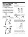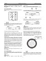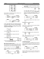
1
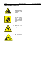
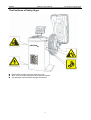
LAUNCH
KWB-4xx User’s Manual
owners. LAUNCH disclaims any and all rights in those
marks.
Copyright Information
All rights reserved! No part of this publication may be
reproduced and stored in any form (electronic, mechanical,
photocopying, recording or other forms) without obtaining
written permission from Shenzhen Launch Tech Co.,
Ltd.(hereinafter refers to as LAUNCH). The manual is
special written for the use of this machine of LAUNCH,
therefore we are not responsible for any use of this
information as applied to other devices.
Neither LAUNCH nor its affiliates shall be liable for damages,
losses, costs, or expenses result from: user or third party’s
personal accident, misuse, or abuse of this unit, or
unauthorized modifications, repairs, or alterations to this unit,
or failure to strictly comply with LAUNCH operating and
maintenance instructions.
LAUNCH shall not be liable for any damages or problems
arising from the use of other accessories or parts other than
original LAUNCH products or LAUNCH approved products.
Declaration: Other product names used herein are for
identification purposes only and the registered trademark
ownership belongs to original companies.
This equipment is intended for use by technical
professionals or maintenance personnel.
Trademark Information
is a registered trademark of LAUNCH TECH.
CO., LTD. in China and other countries. All other LAUNCH
trademarks, service marks, domain names, logos, and
company names referred to in this manual are property
rights of LAUNCH or its affiliates. In countries where any of
the LAUNCH trademarks, service marks, domain names,
logos and company names has not been registered,
LAUNCH claims its ownership for them. Other trademarks
referred to in this manual still belong to the original
registered company. You may not use any trademark,
service mark, domain name, logo, or company name of
LAUNCH or other companies referred to in this manual
without prior permission from the owners. You may contact
LAUNCH by visiting its website at http://www.cnlaunch.com,
or writing to LAUNCH, Xinyang Building, Bagua 4th Road,
Shenzhen, Guangdong Province, P. R. China, if you have
any questions.
General Notice
Other product names used herein are for identification
purposes only and may be trademarks of their respective
i
LAUNCH
KWB-4xx User’s Manual
body when the machine works.
l Do not remove the safety device or keep it from
working properly.
l When the machine is moved, only exert force on the
chassis. Never exert force on the principal shaft under
any condition. Please carry and place it with great
care.
Safety Precautions
Warning
l
l
l
l
Safety Precautions
This manual is an integral part of the machine.
Please read carefully.
Keep the manual for later use when maintaining the
machine.
This machine can only be used for the designated
purposes. Never use it for any other purpose.
The manufacturer is not held responsible for the
damage incurred by improper use or use other than
the intended purpose.
Precautions
l This equipment must be operated by qualified
personnel who have been gone through special
training programs. Any modification or change of
application range to this machine may cause direct or
indirect damages to equipment without obtaining
permission from manufacturer or not following the
instruction of the manual.
l KWB-4xx should be installed on the stable ground.
l Keep 0.6M distance between the back panel and the
wall for good ventilation. Enough room should be left
on both sides of KWB-4xx for convenient operation.
l Do not put KWB-4xx in a place with extreme
temperature or moisture, or near the heating system,
water tap, air-humidifier or furnace.
l Do not put KWB-4xx near the window with sunlight.
Protect the unit with a curtain or shield if necessary.
l Keep the machine from dust, ammonia, alcohol,
thinner or spraying binder.
l People who are no operating the machines should be
kept away when it is used.
l Use appropriate equipment and tools, protective and
safety equipment, including work clothes, blinkers,
working boots and so on.
l Pay special attention to the safety marks stuck on the
machine.
l Do not touch or approach the moving parts by hand or
ii
LAUNCH
KWB-4xx User’s Manual
Descriptions for Safety Signs
l
Do not exert force on
the hanging handle to
avoid falling of the
machine.
l
The wheel protection
must be put down
before
pressing
START button of the
machine to avoid any
injury.
l
High voltage power!
Danger!
l
Do not exert force
on the balance shaft
when the machine is
transported.
iii
The Position of Safety Signs
LAUNCH
KWB-4xx User’s Manual
The Positions of Safety Signs
L AU NC H
u
u
u
Please replace the safety signs if they get blurred or lost.
When one or more safety signs get lost, don’t operate the machine.
The safety signs must be kept within the sight of the operator.
iv
The Position of Safety Signs
LAUNCH
KWB-4xx User’s Manual
Table of Contents
Introduction..................................................................................................................................................................................1
Usage....................................................................................................................................................................................... 1
Features................................................................................................................................................................................... 1
Working Principle ..................................................................................................................................................................... 1
Background Knowledge ........................................................................................................................................................... 1
Technical Parameter ................................................................................................................................................................ 1
Application Scope .................................................................................................................................................................... 1
Working Conditions.................................................................................................................................................................. 1
Equipment Structure...................................................................................................................................................................2
Main Structure.......................................................................................................................................................................... 2
Power Supply Control Board.................................................................................................................................................... 4
Control Panel ........................................................................................................................................................................... 4
Operating Instruction..................................................................................................................................................................6
Preparation............................................................................................................................................................................... 6
Wheel Mounting ....................................................................................................................................................................... 6
General operation .................................................................................................................................................................... 6
Operating Procedures for Special Balance Mode ..................................................................................................................10
ALU Wheel Drum Balance ..................................................................................................................................................... 10
OPT Coincidence Balance Operation .................................................................................................................................... 13
Equipment Calibration ..............................................................................................................................................................15
Self-calibration Program of the Balancer ............................................................................................................................... 15
Automatic Measure scale Calibration Program...................................................................................................................... 15
Self-Testing Program (Testing Position Sensors and Indicators) ........................................................................................... 16
Troubleshooting ........................................................................................................................................................................17
Error Messages of Self-diagnosis .......................................................................................................................................... 17
Frequent Errors and Solution................................................................................................................................................. 17
Maintenance...............................................................................................................................................................................18
Storage and Scrapping .............................................................................................................................................................19
Storage .................................................................................................................................................................................. 19
Scrapping............................................................................................................................................................................... 19
KWB-412 Circuit Diagram.........................................................................................................................................................20
v
LAUNCH
KWB-4xx User’s Manual
Introduction
Technical Parameter
Introduction
Sizes
Item
Max Height
Length
Width
Usage
The KWB-4 series (including KWB-402/412) wheel balancer
features good design, simple operation, strong functions
and high measurement precision, which make it ideal
equipment for measuring the dynamic balance of the wheel.
It can be used for balancing small and medium size tires. It
can also be a great help in car repair garage and tire shops.
l
l
l
l
l
l
l
KWB-412
1350mm(53”)
1200mm(47”)
1000mm(39”)
Noise
Working noise: <70dB (A)
Measure Index
Balance Cycle: 7s
Balance Accuracy :±1g
Features
l
KWB-402
1350mm(53”)
1200mm(47”)
1000mm(39”)
High aptitude, good stability, and high equilibrating
precision.
The design allows you to operate from several
directions; smart outline makes both eyes and minds
pleased.
Measuring arm can automatically measure the hub
diameter and the distance between the wheel and the
cabinet.
Standard computation and calibration function
eliminate the measurement deviation and ensure the
test accuracy.
Different balance modes are available to various
wheels.
Quick and accurate test may reduce your working
intensity and improve your working efficiency.
Simple operation and easy grasp
Extra-large digital display
Electrical Parameters
Model
Power
supply
402
220V
50Hz
402/A
220V
50Hz
402/B
110V
60Hz
402/C
110V
60Hz
412
220V
50Hz
412/A
220V
50Hz
412/B
110V
60Hz
412/C
110V
60Hz
Working Principle
Only when CPU performs self-test and displays normal
information of all units can the user start the balancing
operation. CPU controls the running of principal shaft via
driving interface during balancing operation. The
imbalanced signal detected by the balance sensor is
transmitted to CPU interface through A/D converter. CPU
analyzes comprehensively both the imbalance signal and
the angle signal of principal shaft, calculates the imbalance
value, and then displays the result through LED unit.
Man-machine dialogue can be realized through the
keyboard and LED unit.
Weight
Item
Net Weight
Motor
Power
180W
Max.
wheel D
10--30″
Max.
wheel W
65kg
370W
10--30″
65kg
180W
10--30″
65kg
370W
10--30″
65kg
180W
10--30″
65kg
370W
10--30″
65kg
180W
10--30″
65kg
370W
10--30″
65kg
KWB-402
108 kg
KWB-412
108 kg
Application Scope
Item
Rim Diameter
Rim Width
Background Knowledge
Max
Weight
The imbalance of the wheel causes wobble of the steering
wheel, low adhesion, and wheel jumping, which damages
the wheel and shocks absorber and turning parts. It also
influences the comfort of steering stability and increases fuel
consumption, decreasing economic index of the automobile
directly. Balancing operation will eliminate these
disadvantages and relative loss.
Wheel
KWB-402
10—22″
(254--558mm)
1.5--18″
(38--457mm)
65kg
KWB-412
10--22″
(254--558mm)
1.5--18″
(38--457mm)
65kg
Working Conditions
Working Temperature: 0℃-50℃
Relative Humidity: ≤85%
Transport/store temperature: 0℃-55℃
Altitude: less than 1000m
1
LAUNCH
KWB-4xx User’s Manual
003
004
005
006
007
Equipment Structure
Main Structure
008
009
Note: The main structure of KWB-402 and that of
KWB-412 are similar, here we take KWB-412 as an
example.
KWB-412wheel balancer structure is shown as in Fig 1.
Control Panel
Counterweight
Groove
Hanging Handle
LAUNC H
Balance shaft
Measure Scale
Fig 1
1.
Measure scale — for automatic measurement of the
installation distance of the wheel (wheel distance in
short) and rim diameter, and the accurate position of
the sticking balance block.
Note: The wheel distance and wheel diameter of
KWB-402 need to be entered manually; and the wheel
distance and wheel diameter of KWB-412 can be
entered automatically.
2. Control panel — for man-machine dialogue.
3. Hanging handle-- For hanging cones and the wheel width
scale
4. Counterweight groove — for putting the counterweight.
5. Balance shaft — for supporting the wheel.
6. Wheel protection: for protecting the wheel.
Accessories supplied with the machine are showed in
Fig 2
Description
001
002
Shaft positioning cone
Guide screw
Spring
Locking wing nut assembly
Width measure scale
Standard lead weight
Pliers to attach the balance
weight
Hanging handle
Wheel protection
1
1
1
1
1
2
1
Standardized elements of balancer are shown in the
following figure.
Wheel Protection
No.
Equipment Structure
Amount
4
1
2
LAUNCH
KWB-4xx User’s Manual
Equipment Structure
Standardized elements of KWB-412 wheel dynamic balancer
001
002
005
008
003
004
006
007
009
Fig 2
3
LAUNCH
KWB-4xx User’s Manual
Equipment Structure
Power Supply Control Board
The position of fuse on power supply control board of the
KWB-412 is shown as Fig 3.
The parameters of the two fuses F1 and F2 are:
F1:2A,φ5×20mm,250VAC;
F2:6A,φ5×20mm,250VAC。
1. Display for imbalance value or distance size of
side wheel
2. Indicating for inner side balance point when
indicators are lit
3. Display for static balance value or rim width
4. Indicating for outer side balance point when
indicators are lit
5. Display for imbalance value or diameter size of
side wheel
6. Indication for balance mode and “mm”
F2
2A
F1
6A
F2
inner
all 5
all 5
outer
The meaning of control panel
F1
F
Fig 3
Control Panel
The control panel of KWB-412 is as shown in
Fig. 4
7. Key (a) used to enter the wheel distance manually
8. Key (b) used to enter the rim width manually
9. Key (d) used to enter the rim diameter manually
10. Key for self-diagnosis (LED self-check) and for
self-calibration (required to be used with key C)
11. Key for dis-balance recalculation/self-calibration
12. Selection key for “inch←→mm”
13. High accuracy balance key
14. Dis-balance optimized key
15. Key for balance mode selection
16. Key for dynamic balance or different static balance
mode selection
17. Emergency stop button
18. Start button
Fig 4
The meaning of display panel
Caution:
In order to avoid damaging the film of control
panel, please don’t touch the keys with sharp
material.
Composite keys for function conversion
4
LAUNCH
KWB-4xx User’s Manual
Equipment Structure
both Auto mode and Manual mode).
1. [ STOP ] + [ a ↑ ] + [ a ↓ ]
Conversion keys
for the measurement unit of “gram/ounce”.
First, please press [STOP] button and hold it, then
press [ a ↑ ] and [ a ↓ ] at the same time, the
information displayed on the control panel will put out;
after a while, please release button [ a ↑ ], [ a
↓ ] and [STOP] in turn, the previous tested data will
be redisplayed at once but with another kind of unit
system.
5. [ STOP ] + [ OPT ]
Keys for diameter data
adjustment of auto measure scale function.
The diameter data of different vehicle wheels can be
stored into CPU through this operation, and the data
can keep stored even after balancer shutdown (the
detailed operation will be described later).
Note: The different sequence for releasing the keys
may result in the different data displayed, but it is
not necessary for operator to perform other
operations, directly pressing [Start] button is ok.
2.
[ STOP ] + [ C ]
The keys for measurement
mode selection after putting down the wheel
protection.
Please press [STOP] button and hold it, then press
[C] button and hold it; release [ C ] and [ STOP ]
button in turn, the measurement mode will be
alternated between “Put down the wheel protection to
start measurement” and “Put down the wheel
protection to start measurement by pressing
[ START ] button”.
3. [ STOP ] + [ FINE ]
The keys for entering the
status of measure scale distance calibration. The
self-calibration for measure scale is required to
perform when starting the balancer each time,
otherwise the correct measurement status cannot be
entered (the detailed information about self-calibration
will be described later).
4. [ D ] + [ C ]
The keys for outside parameter
calibration before measurement.
The keys are used to calibrate the CPU memories
corresponding to the wheelbase, rim width and rim
diameter of different wheels, so as to ensure the
measurement accuracy (it is necessary to calibrate in
5
LAUNCH
KWB-4xx User’s Manual
Operating Instruction
wheel with a locking wing nut.
Mounting Method 2
This method is suitable for the wheel to be positioned with
its central hole, especially when the central position surface
cannot be correctly positioned due to deformation.
Preparation
l
Fit a conical spring, then select a right size conical
casing and fit it onto the balance shaft in reverse. See
Fig 7.
Fig 7
Locking wing nut
Fit conical spring
(big end inward)
l
Fit a matching end cap (optional) onto the locking wing
nut.
Fit the wheel onto the conical casing and fasten it with
a end cap and a locking wing nut.
End cap
l
Fit the wheel
Ø
Attention:
The max weight of the wheel cannot exceed 65kg.
Remove any counterweight and other foreign body
from the wheel before mounting it avoiding any
danger. When remove the counterweight, the
demounting/mounting pliers supplied with the
machine should be used (Fig. 5).
Clean the contact surfaces between the shaft and
the conical casing with alcohol or gasoline before
mounting the wheel to avoid any influences on
installation accuracy.
Put the balancer on level ground as possible as
you can.
Fit conical casing
Ø
Locking
wing nut
Mount
wheel
Caution:
The equipment can only be operated by qualified
personnel with special training. Use appropriate tools,
protective and safety equipment, wearing protective
work clothes, such as blinkers, and working boots.
Ø
Ø
Fit conical
casing
Operating Instruction
Fig 5
General operation
Switch on the Machine
l Before switching on the machine, please ensure that
the power supply selected meet the requirements on
the name plate.
l Turn on the power supply switch on the left side of the
machine (Fig 8).
Wheel Mounting
Mounting Method 1
It is suitable for the wheel that can be positioned with its
center hole.
Fig 6
l
l
Fig 8
Fit the wheel onto the balance shaft close up the
flange (Fig 6).
Select a right size conical casing, and then tighten the
l
6
The display panel will show the version No. of main
board (Fig 9).
LAUNCH
KWB-4xx User’s Manual
Operating Instruction
side wall of the wheel for about 2 seconds, the LED
will display the information as shown in Fig 12.
Fig 9
l
And then the display panel will show the parameter
(default value) of the object to be balanced (Fig 10).
Fig 12
l
Fig 10
Function Selection
After switching on the wheel balancer, the function status is
default status (i.e. the common dynamic balance status),
because this function status is selected in common
circumstances, more specifically, this function status can be
selected in case of the pothook style counterweight can be
used on both sides of wheel rim edge.
Only single-side balance is required to be performed for
static balance. In this case the whole wheel is taken as
having one side surface only.
Double-side balance is required to be performed for
dynamic balance.
The lead weight is required to be mounted only on the
outside of wheel when performing static balance operation;
and that is required to be mounted on both inner side and
outside of wheel when performing dynamic balance.
Fig 13
l
Measure the rim width with width scale according to
Fig 14.
Read width data
(Note: other function selection and application will be
described later).
Fig 14
Inputting Wheel Data
It is important for operator to know how to input data
correctly because the wrong data input may directly
influence the test result of next step.
Known a=5.0″, b=6.0″, d=15.0″.
KWB-412 balancer has the function of measuring the
distance (a value) between the wheel and the balancer
cabinet and the rim diameter (a value) automatically.
KWB-412 is taken as an example:
l Pull out the measure scale into contact with the inside
wall of the wheel rim, the display information on the
control panel will go out because of the instable data
(Fig 11).
l
l
Input the data read via Up--Down key
.
The control panel will display the information as shown
in Fig 15.
Fig 15
Imbalance value measurement
Attention:
Make sure to put down the wheel protection before
pressing [START] for safety operation.
Ø Do not raise the wheel protection when the wheel is
rotating. If abnormal situation occurs, press [STOP]
first, then turn off the power. Don’t raise wheel cover
until the wheel stops.
Ø Do not touch the machine during a wheel spin.
Otherwise, the balance effect will be influenced.
The procedures for imbalance value measurement are as
follows:
l Put down the wheel protection to start the balancer
(there are many kinds of start modes, please refer to
the paragraph of “Composite keys for function
Ø
a value
l
Reset the automatic measure scale, the control panel
will display the data measured just now, and “a” value
and “d” value are also automatically measured and
displayed as shown in Fig 13.
Fig 11
Keep the automatic measure scale close to the inner
7
LAUNCH
l
KWB-4xx User’s Manual
conversion” for other operating methods), and all
LEDs will go out at this moment.
After about 7 seconds, the control panel displays the
imbalance value of the wheel, as shown in Fig 16.
Compensation for wheel imbalance value
l According to the previous paragraph, attach the
relative counterweight on the imbalance point of the
rim. Attach the balance weight on the imbalance point
as possible as you can, otherwise the compensation
error will be produced.
l Perform the imbalance measurement operation again;
l The display information of the re-measurement
operation is as shown in Fig 20.
Fig 16
l
l
Operating Instruction
Meaning of the information displayed:
☆ “35” indicates that the imbalance value of the wheel
inner side is 35g;
☆ “OPT” indicates that the imbalance value of this
wheel is larger, and should be optimized. Please
refer to the paragraph of “OPT Coincidence
Balance Operation” for detailed operating
procedures;
☆ “60” indicates that the imbalance value of the wheel
outside is 60g;
☆ If all indicators at one side are lit, it indicates that
the highest point at this side of the wheel is the
imbalance position.
Fig 20
l
The meaning of the information displayed:
“PAS” indicates that the compensation for this side is
up to standard (imbalance value < 5g);
l
key, the control panel will display the
Press
actual accurate imbalance value as shown in Fig 21.
The balance operation is successful.
key, the control panel will display the
Press
actual accurate imbalance value as shown in Fig 17.
Fig 21
Attention:
Generally speaking, it is up to standard if the imbalance
value of the wheel is less than 5g, for the balance weight
uses quinary system, i.e. 5g, 10g and 15g, etc.
Fig 17
l
Rotate the wheel, if all indicators at the outside of the
wheel are lit (see Fig 18), it indicates that the highest
point at the outside is the imbalance position (see Fig
19). The method to determine the imbalance position
for inner side of the wheel is the same as that for
outside.
Static—dynamic balance mode conversion
The method for attaching the balance weight during static
balance measurement is different from that during dynamic
balance measurement. Press
Fig 18
key to select static
balance mode, and repress
key to return to the
dynamic balance mode.
l Lead-attaching method during static balance
measurement: If you want to measure the wheel of
motorcycle or the wheel of which both sides can not be
key.
attached with balance lead, please press
After the tested data of imbalance value is displayed,
please press
key to select the lead-attaching
method for static balance, and then rotate the wheel
slowly. When the control panel displays the information
as shown in Fig 22, all indicators at the inner side are
lit. Attach the balance lead at the inner side of the
wheel spoke at this moment (Fig 23).
Fig 19
8
LAUNCH
KWB-4xx User’s Manual
Fig 22
Fig 23
9
Operating Instruction
LAUNCH
KWB-4xx User’s Manual
Operating Procedures for
Special Balance Mode
Attention:
KWB-402 balancer has no automatic measure scale, so it
cannot use the accurate lead-attaching mode.
ALU—1 Balance Mode
After selecting ALU—1 mode, the indicators are as shown in
Fig 26.
ALU Wheel Drum Balance
Keep pressing
key to switch ALU operating mode.
Wheel drum balance (i.e. alloy steel rim balance) includes 3
kinds of mode: ALU—1, ALU—2 and ALU—S. The
lead-attaching surface of ALU—S can be set artificially
according to the requirement, and can be balanced with
implicated counterweight via assistant implicated program.
Under ALU—1 and ALU—2 mode, the different platform can
be selected to perform the lead-attaching operation
according to the specific shape of the wheel drum section
(see Fig 24 and Fig 25). In this way, the accurate balance
position and the more accurate balance result can be
obtained. Press
key one time, the ALU—1 mode is
entered; press
key two times in succession, the
Fig 26
key to recalculate the imbalance value of
Press
inner side and outside, the control panel will display the
information as shown in Fig 27.
ALU—2 mode is entered; press
key three times in
succession, the ALU—S mode is entered.
Lead-attaching
position
Operating Instruction
Lead-attaching
position
Fig 27
The specific operating procedures are as follows:
Rotate the wheel, let all indicators at inner side (or outside)
lit. Let the lead weight side with sticking protection paper
upwards, and then lift the protection paper as shown in Fig
28.
Fig 24
Lead-attaching
position
Lead-attaching
position
Fig 28
Move the lead weight slowly to the lead-attaching position,
and attach it when arriving at the lead-attaching position.
Finishing the lead-attaching operation for inner side and
outside of the wheel is finishing ALU—1 operation. Perform
the rotating test one more time to identify the balance effect.
Note: Keep the rim surface clean to ensure the lead
weight stuck on it firmly. Perform lead-attaching
Fig 25
10
LAUNCH
KWB-4xx User’s Manual
operation, if necessary, after cleaning the rim surface
with appropriate amount of organic solvent or
detergent.
Operating Instruction
measurement.
Step 1: Input the number of the wheel spokes
After inputting the data of the wheel, and before selecting
ALU—2 Balance Mode
After selecting ALU—2 mode, the indicators are as shown in
Fig 29.
key first. The
ALU mode, please press
control panel will display the information as shown in Fig 31.
Fig 31
key again to confirm. The control
Press
panel will display the information as shown in Fig 32.
Fig 29
key to recalculate the imbalance value of
Press
inner side and outside, the control panel will display the
information as shown in Fig 30.
Fig 32
Attention:
If it is necessary to resolute the imbalance value to wheel
spokes, the number of the wheel spokes must be input; if
not, please skip Step 1 directly.
Fig 30
The specific operating procedures are as follows:
Step 2: Size-inputting method in ALU—S balance mode
aI and aE indicate the lead-attaching position at the inner
side of the wheel rim;
dI and dE indicate the
lead-attaching position at the outside of the wheel rim.
Rotate the wheel, let any one of the wheel spokes on 12
o’clock position as shown in Fig 33.
Rotate the wheel, let all indicators at inner side lit. The
highest point of the rim inner side edge is the inner side
balance point when all indicators are lit. Please attach the
lead weight at the inner side of the rim according to the
displayed value.
Continue to rotate the wheel, let all indicators at the outside
of the wheel lit. The outside balance point is in the line
parallel to the axis of the highest point close to the outside
of the rim inside wall. Let the lead weight side with sticking
protection paper upwards, and then lift the protection paper
as shown in Fig 28.
Move the lead weight slowly to the lead-attaching position,
and attach it when arriving at the lead-attaching position.
Finishing the lead-attaching operation for inner side and
outside of the wheel is finishing ALU—2 operation. Perform
the rotating test one more time to identify the balance effect.
Position of the wheel
spoke
Attention:
The measure scale cannot be used under ALU—1 and
ALU—2 mode.
Fig 33
ALU—S Balance Mode
ALU—S balance mode is suitable to very special wheel rim.
ALU—2 mode cannot ensure the balance of this kind of
special rim.
Press
key to perform the dynamic balance
operation one time, and then select ALU—S balance mode.
The control panel will display the information as shown in
Fig 34.
Attention:
Please input the number of wheel spoke before
11
LAUNCH
KWB-4xx User’s Manual
l
l
Operating Instruction
If it is necessary to resolute the imbalance value to the
wheel spokes, the system will enter Step 4 directly
after resolution.
If it is not necessary to resolute the imbalance value to
the wheel spokes, please press
key (press [STOP] first, and then [ALU]) directly to
perform the accurate lead-attaching operation. The
control panel will display the information as shown in
Fig 38.
Fig 34
Input the data for lead-attaching position according to the
data displayed in Fig 35 and Fig 36.
Fig 35
Fig 38
The operating procedures are the same as that of
Step 4.
Fig 36
Step 4: Resolution for imbalance value
Let dE = 0.8 dI (default value). If dI changed, dE will return
to the default value. The length of the counterweight is
automatically considered as 14mm when the system
calculates the distance between the balancer and the center
of gravity of the counterweight.
a): Press
key, the control panel will display
Press
the information as shown in Fig 39.
Fig 39
key to change the value of aI.
The resolution of the imbalance value is into 20g and 10g.
b): Press
key to change the value of aE.
Press
key to enter the accurate
lead-attaching mode as shown in Fig 40.
c): Press
key to change the value of dI.
Fig 40
d): Keep pressing
key and press
key to change the value of De (Fig 36).
Lead-attaching operation
The left screen displays the imbalance value at the inner
side of the wheel rim. Rotate the wheel slowly, pull out the
width scale when all indicators at inner side of the wheel are
lit (Fig 41).
Step 3: Calculating imbalance value
After inputting the data of lead-attaching position, please
rotate the wheel. If it is necessary to resolute the imbalance
value, please let any one of the wheel spokes on 12 o’clock
key to
position as shown in Fig 33, then press
perform measurement, so as to get a new imbalance value
(Fig 37).
Fig 41
Keep the width scale close to the inner side wall of the
wheel rim, the control panel will display the information as
shown in Fig 42.
Fig 37
12
LAUNCH
KWB-4xx User’s Manual
Operating Instruction
Wheel balance operation is finished.
Fig 42
Press
Attach the lead weight on the position indicated by the
measure scale as shown in Fig 43.
key to cancel this function.
Attention:
Press
key to check the balance accuracy. The
balance accuracy is 1g after finishing the balance operation.
OPT Coincidence Balance Operation
This program is used for confirming the best coincidence
position between the rim and tyre, complementing the
imbalance of the rim with the imbalance of the tyre, so as to
reduce the weight of the balance lead added, and reduce
the noise caused by bad coincidence between the rim and
tyre during driving. Generally speaking, user needn’t
perform this operation; only in special case—when the
wheel satisfies the conditions of coincidence balance, can
the experienced personnel perform this operation.
Fig 43
Rotate the wheel slowly until the right screen displays a
imbalance value as shown in Fig 44.
Before performing the coincidence balance operation,
please install the wheel on the balancer to perform the
dynamic balance operation. It is only necessary to measure
the imbalance value, not necessary to stick the lead weight.
After operation, the control panel will display the information
as shown in Fig 48.
Fig 44
Pull out the measure scale, and keep the measure scale
close to the inner side wall of the wheel rim, the control
panel will display the information as shown in Fig 45.
Fig 48
The balancer makes the judgement above-mentioned
according to the imbalance conditions of the wheel (the
single side imbalance value of dynamic balance is more
than 30g).
Fig 45
Attach the lead weight on the position indicated by the
measure scale as shown in Fig 43.
OPT 1
Rotate the wheel slowly again until the right screen displays
the second imbalance value as shown in Fig 46.
Put the wheel on the balancer, and then press
key
to perform OP.1 measurement. After the wheel stops
rotating, rotate the wheel slowly until all indicators are lit.
Mark the highest place of the wheel outside (the side with
the imbalance value of more than 30g) with chalk. The
control panel will display the information as shown in Fig 49.
Fig 46
Pull out the measure scale, and keep the measure scale
close to the inner side wall of the wheel rim, the control
panel will display the information as shown in Fig 47.
Fig 49
Meanwhile mark the highest place of the rim outside with
Fig 47
chalk, and then press
measurement phase.
Attach the lead weight on the position indicated by the
measure scale as shown in Fig 43.
13
key to enter OP.2
LAUNCH
KWB-4xx User’s Manual
OPT 2
The screen will, at that moment, display the information as
shown in Fig 50.
Fig 50
Remove the wheel from the balancer, rotate the outer tyre
relative to the rim, let chalk mark on the outer tyre rotated by
180 degrees. After this, please install the wheel on the
balancer again to enter OP.3 phase.
OPT 3
After entering OP.3 phase, please press
key again
to perform rotating operation once more; along with the
finish of third rotating operation, the screen will display the
optimized result as shown in Fig 51.
Fig 51
OPT procedures are finished.
Press
key to return to OP.1 phase again, the control
panel will display the information as shown in Fig 49.
l
l
Attention:
Please perform OPT operation according to the
procedures above-mentioned strictly, otherwise the
mistakes will occur.
If the imbalance value cannot be up to the requirement,
please repeat the procedures from OP.1 to OP.3.
14
Operating Instruction
LAUNCH
KWB-4xx User’s Manual
Operating Instruction
Automatic Measure scale Calibration
Program
Equipment Calibration
l
Automatic Measure scale Distance Calibration
Self-calibration Program of the Balancer
Attention:
The self-calibration program should be run after the
equipment’s first installation or if the measurement accuracy
of the equipment is suspect, to ensure the measurement
accuracy of the balancer.
Press
key at the same time, the
control panel will display the information as shown in Fig 55.
Turn on the power supply switch of the balancer, install a
wheel with medium size (13″--15″), input the data of the
Fig 55
Move the measure scale to “0” position and hold it, as
shown in Fig 56.
key at the same
wheel rim and press
time. The control panel will display the information as shown
in Fig 52.
0 Position
Fig 52
Fig 56
Release
key, put down the wheel
Press
key at the same time, the control panel will
display the information as shown in Fig 57.
key to rotate the main-shaft.
protection, and press
The control panel will display the information as shown in
Fig 53 when the main-shaft stops rotating.
Fig 57
Move the measure scale to “15” position and hold it, as
shown in Fig 58.
Fig 53
Put down the wheel protection, and attach 100g (3.5oz)
counterweight on the outside of the wheel rim. Put down the
15 Position
wheel protection again, and press
key to re-rotate
the main-shaft. The control panel will display the information
as shown in Fig 54 when the main-shaft stops rotating.
Fig 58
Fig 54
Press
key at the same time, the control panel will
display the information as shown in Fig 59.
The self-calibration is finished, and the self-calibration data
is stored in computer memory, which cannot be lost even
after the balancer shutdown. The wheel balance operation
can be performed after above operating procedures.
Fig 59
Move the measure scale to the original position, then the
15
LAUNCH
KWB-4xx User’s Manual
Operating Instruction
calibration operation is finished.
l Automatic Measure scale Diameter Calibration
Install a wheel rim with known diameter, and then lock it.
Fig 63
The position sensor can be tested at that moment. Rotate
the wheel manually and slowly, indicator ALUI starts flashing,
and “0” will appear on the right screen when “0” position on
the main-shaft passes across the photoelectric sensor as
shown in Fig 64.
key, the control panel will
Press
display the information as shown in Fig 60.
Fig 60
Fig 64
Once the wheel turns by one circle, the [0] will appear on
right screen one time. When the wheel rotates to the
reverse direction, the indicator ALUS will start flashing.
key to input
14.0 is the default value. Press
the diameter (10--18″) of the wheel rim installed. Press
key, the control panel will display the information as
shown in Fig 61.
Press
key, a number will be displayed on the right
screen, which is the distance between the inner side wall of
the wheel rim and the balancer cabinet. When moving the
measure scale, this number is changed, too.
Fig 61
key, a number will be displayed on the left
Press
screen, which is the diameter of the wheel rim. When
swaying the measure scale, this number is changed, too.
Move the measure scale to the position of diameter
measurement and hold it, and then press
key at
the same time, the control panel will display the information
as shown in Fig 62.
Press
key at current status to return to
the procedure of calibrating the diameter of the measure
scale.
Fig 62
key to return to the procedure of
Press
calibrating the distance of automatic measure scale.
Reset the measure scale, the calibration operation is
finished.
Attention:
Attention:
During calibration, if input error occurs, please press [STOP]
key to cancel it.
The operator can press
operation at any time.
Self-Testing Program (Testing Position
Sensors and Indicators)
Press
key, from left to right, the indicators flash
one by one, and the control panel will display the
information as shown in Fig 63.
16
key to exit the self-testing
LAUNCH
KWB-4xx User’s Manual
Phenomenon
Troubleshooting
No
display
when turn on
the machine.
Error Messages of Self-diagnosis
2.
3.
4.
5.
7.
8.
Failures of the single phase motor or the power supply
board.
Low rotating speed or no wheel mounted on the
machine (with tire).
The imbalance value is too big. Change another wheel
to test.
Errors with power supply or position sensor.
The wheel protection is not put down.
Damages of the memory or losses of the signal.
Wrong calibration program or damages of the
computer board or the sensor
Cause
Solution
1.
Check whether
the outer power
supply is normal.
2.
Failures of the
computer board
Normal display
but failures of
[START]
button, and a, b
and d inputting
keys.
1.
Touch switches
are not sensitive.
2.
Machine dies.
Normal display
but unable to
stop after start,
with
wrong
imbalance
value.
1.
2.
Error messages of self-diagnosis are showed below:
1.
Troubleshooting
1.
Check the outer
power supply.
2.
Replace
the
computer board.
1.
Open the cover
and insert the
pins of touch
switches tightly.
2.
Restart
machine.
Loose
connection
between
the
computer board
and the power
supply board.
1.
Tighten
the
connection
between
the
computer board
and the power
supply.
Failures of the
computer board
2.
Replace
the
computer board.
Slow start, bad
brake,
and
inaccurate
imbalanced
value
The
driving
becomes loose.
belt
Normal work
but
with
inaccurate
imbalance
value
1.
Calibrated value
changes.
2.
3.
the
Replace the driving
belt or adjust tension
of the V belt.
1.
The body is not
stable.
Re-calibrate it
according to the
User’s manual.
2.
Influences
of
cones or locking
wing nuts.
Solve failures
according
to
check result.
3.
If the failure still
exists, replace
the computer
board.
4.
Re-fasten
locking
wing
nuts.
4.
The wheel is not
mounted tightly.
5.
Unstable power
supply.
6.
Big fluctuation of
power voltage.
7.
Failures of the
raster
display
and its circuit.
Attention:
If the problems can not be fixed through above solutions,
please contact the technical support personnel.
Frequent Errors and Solution
17
LAUNCH
KWB-4xx User’s Manual
Maintenance
Attention:
Only the specialized technician can do the maintenance.
Before any maintenance is performed, disconnect the power
and keep the plug within the sight of the maintenance
personnel.
To keep the wheel balancer in good condition and to prolong
its work life, it is necessary to do regular maintenance
according to the instructions of this manual. Otherwise, the
normal operation and reliability of the machine will be
influenced, or personal injury would be caused.
l
Keep the machine and working area clean, prevent
dust from entering the moving parts.
l
Keep the balance shaft clean (clean with diesel oil
or alcohol) and lubricated.
l
Regularly calibrate the machine. See Installation
and Parts Manual for details.
l
Regularly check and adjust the tension of the belt.
l
Check all connecting parts and bolts regularly and
tighten them if necessary.
18
Maintenance
LAUNCH
KWB-4xx User’s Manual
Storage and Scrapping
Storage
When the equipment needs to be stored for a long extended
period of time:
l Disconnect the power.
l Lubricate all the parts that need to be lubricated:
main shaft and etc.
l Protect the machine with plastic cover against dust.
Scrapping
When the equipment can no longer be used, disconnect the
power and dispose it in accordance with the local law and
regulations.
19
Storage and Scrapping
LAUNCH
KWB-4xx User’s Manual
KWB-412 Circuit Diagram
Transformer
Aviation Plug
Motor
Wheel Protection Interface
Main Board Box
Power Supply Box
Aviation Plug
Aviation Plug
Sensor Interface
Measure Scale Interface
KWB-412 Circuit Diagram
20
Raster Interface
LAUNCH
Warranty
-THIS WARRANTY IS EXPRESSLY LIMITED TO
PERSONS WHO PURCHASE LAUNCH PRODUCTS FOR
PURPOSES OF RESALE OR USE IN THE ORDINARY
COURSE OF THE BUYER’S BUSINESS.
LAUNCH products is warranted against defects in materials
and workmanship for one year from date of delivery to the
user. This warranty does not cover any part that has been
abused, altered, used for a purpose other than for which it
was intended, or used in a manner inconsistent with
instructions regarding use. The exclusive remedy for any
automotive meter found to be defective is repair or
replacement, and LAUNCH shall not be liable for any
consequential or incidental damages. Final determination of
defects shall be made by LAUNCH in accordance with
procedures established by LAUNCH. No agent, employee,
or representative of LAUNCH has any authority to bind
LAUNCH to any affirmation, representation, or warranty
concerning LAUNCH products.
Declaration
The above warranty is able to replace any warranty in other
forms.
Order Information
Replaceable and optional parts can be ordered directly from
your LAUNCH authorized supplier. Your order should
include the following information:
1. Quantity
2. Part code
3. Item description
Customer Service
If you have any questions on the operation of the machine,
please contact us:
Tel: 86-755-82269474, or fax: 86-755-82264570
If your machine requires repair service, return it to the
manufacturer with the sales invoice, the warranty sheet, the
quality certificate and a note describing the problem. If the
machine is determined to be in warranty, LAUNCH will
repair or replace at no charge, also repay the transport fee
to the customer. If the machine is determined to be out of
warranty, it will be repaired for a nominal service charge
plus return freight. Our address is as follows:
Attn: Overseas Department
LAUNCH TECH. CO., LTD.
KWB-4xx User’s Manual
Xinyang Building, Bagua 4th Road,
Shenzhen, Guangdong Province,
P. R. China
P.C.: 518029